EP3444002B1 - Dispositifs à ultrasons de coaptation - Google Patents
Dispositifs à ultrasons de coaptation Download PDFInfo
- Publication number
- EP3444002B1 EP3444002B1 EP18177361.5A EP18177361A EP3444002B1 EP 3444002 B1 EP3444002 B1 EP 3444002B1 EP 18177361 A EP18177361 A EP 18177361A EP 3444002 B1 EP3444002 B1 EP 3444002B1
- Authority
- EP
- European Patent Office
- Prior art keywords
- magnet
- balloon
- patient
- tube
- distal end
- Prior art date
- Legal status (The legal status is an assumption and is not a legal conclusion. Google has not performed a legal analysis and makes no representation as to the accuracy of the status listed.)
- Active
Links
Images


Classifications
-
- A—HUMAN NECESSITIES
- A61—MEDICAL OR VETERINARY SCIENCE; HYGIENE
- A61B—DIAGNOSIS; SURGERY; IDENTIFICATION
- A61B8/00—Diagnosis using ultrasonic, sonic or infrasonic waves
- A61B8/08—Clinical applications
- A61B8/0833—Clinical applications involving detecting or locating foreign bodies or organic structures
- A61B8/0841—Clinical applications involving detecting or locating foreign bodies or organic structures for locating instruments
-
- A—HUMAN NECESSITIES
- A61—MEDICAL OR VETERINARY SCIENCE; HYGIENE
- A61B—DIAGNOSIS; SURGERY; IDENTIFICATION
- A61B8/00—Diagnosis using ultrasonic, sonic or infrasonic waves
- A61B8/42—Details of probe positioning or probe attachment to the patient
- A61B8/4209—Details of probe positioning or probe attachment to the patient by using holders, e.g. positioning frames
-
- A—HUMAN NECESSITIES
- A61—MEDICAL OR VETERINARY SCIENCE; HYGIENE
- A61B—DIAGNOSIS; SURGERY; IDENTIFICATION
- A61B8/00—Diagnosis using ultrasonic, sonic or infrasonic waves
- A61B8/48—Diagnostic techniques
- A61B8/481—Diagnostic techniques involving the use of contrast agents, e.g. microbubbles introduced into the bloodstream
-
- A—HUMAN NECESSITIES
- A61—MEDICAL OR VETERINARY SCIENCE; HYGIENE
- A61J—CONTAINERS SPECIALLY ADAPTED FOR MEDICAL OR PHARMACEUTICAL PURPOSES; DEVICES OR METHODS SPECIALLY ADAPTED FOR BRINGING PHARMACEUTICAL PRODUCTS INTO PARTICULAR PHYSICAL OR ADMINISTERING FORMS; DEVICES FOR ADMINISTERING FOOD OR MEDICINES ORALLY; BABY COMFORTERS; DEVICES FOR RECEIVING SPITTLE
- A61J15/00—Feeding-tubes for therapeutic purposes
- A61J15/0003—Nasal or oral feeding-tubes, e.g. tube entering body through nose or mouth
-
- A—HUMAN NECESSITIES
- A61—MEDICAL OR VETERINARY SCIENCE; HYGIENE
- A61J—CONTAINERS SPECIALLY ADAPTED FOR MEDICAL OR PHARMACEUTICAL PURPOSES; DEVICES OR METHODS SPECIALLY ADAPTED FOR BRINGING PHARMACEUTICAL PRODUCTS INTO PARTICULAR PHYSICAL OR ADMINISTERING FORMS; DEVICES FOR ADMINISTERING FOOD OR MEDICINES ORALLY; BABY COMFORTERS; DEVICES FOR RECEIVING SPITTLE
- A61J15/00—Feeding-tubes for therapeutic purposes
- A61J15/0026—Parts, details or accessories for feeding-tubes
- A61J15/008—Sensor means, e.g. for sensing reflux, acidity or pressure
- A61J15/0088—Sensor means, e.g. for sensing reflux, acidity or pressure for sensing parameters related to the device
-
- A—HUMAN NECESSITIES
- A61—MEDICAL OR VETERINARY SCIENCE; HYGIENE
- A61M—DEVICES FOR INTRODUCING MEDIA INTO, OR ONTO, THE BODY; DEVICES FOR TRANSDUCING BODY MEDIA OR FOR TAKING MEDIA FROM THE BODY; DEVICES FOR PRODUCING OR ENDING SLEEP OR STUPOR
- A61M25/00—Catheters; Hollow probes
- A61M25/01—Introducing, guiding, advancing, emplacing or holding catheters
- A61M25/0105—Steering means as part of the catheter or advancing means; Markers for positioning
- A61M25/0133—Tip steering devices
- A61M25/0158—Tip steering devices with magnetic or electrical means, e.g. by using piezo materials, electroactive polymers, magnetic materials or by heating of shape memory materials
-
- A—HUMAN NECESSITIES
- A61—MEDICAL OR VETERINARY SCIENCE; HYGIENE
- A61B—DIAGNOSIS; SURGERY; IDENTIFICATION
- A61B1/00—Instruments for performing medical examinations of the interior of cavities or tubes of the body by visual or photographical inspection, e.g. endoscopes; Illuminating arrangements therefor
- A61B1/00147—Holding or positioning arrangements
- A61B1/00158—Holding or positioning arrangements using magnetic field
-
- A—HUMAN NECESSITIES
- A61—MEDICAL OR VETERINARY SCIENCE; HYGIENE
- A61B—DIAGNOSIS; SURGERY; IDENTIFICATION
- A61B1/00—Instruments for performing medical examinations of the interior of cavities or tubes of the body by visual or photographical inspection, e.g. endoscopes; Illuminating arrangements therefor
- A61B1/005—Flexible endoscopes
- A61B1/01—Guiding arrangements therefore
-
- A—HUMAN NECESSITIES
- A61—MEDICAL OR VETERINARY SCIENCE; HYGIENE
- A61B—DIAGNOSIS; SURGERY; IDENTIFICATION
- A61B17/00—Surgical instruments, devices or methods
- A61B2017/00831—Material properties
- A61B2017/00876—Material properties magnetic
-
- A—HUMAN NECESSITIES
- A61—MEDICAL OR VETERINARY SCIENCE; HYGIENE
- A61B—DIAGNOSIS; SURGERY; IDENTIFICATION
- A61B17/00—Surgical instruments, devices or methods
- A61B17/34—Trocars; Puncturing needles
- A61B17/3403—Needle locating or guiding means
- A61B2017/3413—Needle locating or guiding means guided by ultrasound
-
- A—HUMAN NECESSITIES
- A61—MEDICAL OR VETERINARY SCIENCE; HYGIENE
- A61B—DIAGNOSIS; SURGERY; IDENTIFICATION
- A61B90/00—Instruments, implements or accessories specially adapted for surgery or diagnosis and not covered by any of the groups A61B1/00 - A61B50/00, e.g. for luxation treatment or for protecting wound edges
- A61B90/36—Image-producing devices or illumination devices not otherwise provided for
- A61B90/37—Surgical systems with images on a monitor during operation
- A61B2090/378—Surgical systems with images on a monitor during operation using ultrasound
-
- A—HUMAN NECESSITIES
- A61—MEDICAL OR VETERINARY SCIENCE; HYGIENE
- A61M—DEVICES FOR INTRODUCING MEDIA INTO, OR ONTO, THE BODY; DEVICES FOR TRANSDUCING BODY MEDIA OR FOR TAKING MEDIA FROM THE BODY; DEVICES FOR PRODUCING OR ENDING SLEEP OR STUPOR
- A61M25/00—Catheters; Hollow probes
- A61M25/01—Introducing, guiding, advancing, emplacing or holding catheters
- A61M25/0105—Steering means as part of the catheter or advancing means; Markers for positioning
- A61M2025/0166—Sensors, electrodes or the like for guiding the catheter to a target zone, e.g. image guided or magnetically guided
-
- A—HUMAN NECESSITIES
- A61—MEDICAL OR VETERINARY SCIENCE; HYGIENE
- A61M—DEVICES FOR INTRODUCING MEDIA INTO, OR ONTO, THE BODY; DEVICES FOR TRANSDUCING BODY MEDIA OR FOR TAKING MEDIA FROM THE BODY; DEVICES FOR PRODUCING OR ENDING SLEEP OR STUPOR
- A61M25/00—Catheters; Hollow probes
- A61M25/10—Balloon catheters
- A61M2025/1043—Balloon catheters with special features or adapted for special applications
- A61M2025/1079—Balloon catheters with special features or adapted for special applications having radio-opaque markers in the region of the balloon
-
- A—HUMAN NECESSITIES
- A61—MEDICAL OR VETERINARY SCIENCE; HYGIENE
- A61M—DEVICES FOR INTRODUCING MEDIA INTO, OR ONTO, THE BODY; DEVICES FOR TRANSDUCING BODY MEDIA OR FOR TAKING MEDIA FROM THE BODY; DEVICES FOR PRODUCING OR ENDING SLEEP OR STUPOR
- A61M25/00—Catheters; Hollow probes
- A61M25/10—Balloon catheters
Definitions
- the present invention relates generally to placement of medical devices within a body in the medical field, and more particularly to devices for ultrasound-guided placement of medical devices, such as catheters, conduits, carriers, electrodes, and the like into a patient's body.
- a wide variety of medical procedures require placement of medical devices at various locations within a patient's body. For instance, certain procedures may require the placement of electrodes within a patient's spine, or attachment of electrodes to heart tissue, or the like. In other procedures, medical staff may wish to place temperature probes or heating wires at various locations within patient's body. Further, for cancer treatment, medical staff may wish to place radioactive seeds or deliver therapeutic medications deep within a patient's body, including directly into internal organs.
- medical staff may wish to place catheters or other fluid or material-carrying conduits within the patient's body for delivery of medications or other materials, for carrying forceps, biopsy instruments or the like into the patient's body, for providing suctioning to various parts of a patient's body, and many other procedures involving the placement of medical devices within the patient's body.
- Procedures for placing such medical devices vary widely from application to application, but all carry the common aspect of presenting challenge to the medical staff in manipulating such medical devices within the patient's body to route them to their intended location and position them for their intended use at that location.
- PEG Percutaneous Endoscopic Gastrostomy
- a patient is placed in the supine position.
- a nasal or oral gastric tube is then introduced into the patient's stomach.
- Gastric fluid is removed using suction, such as through fenestrations at the distal end of the nasal or oral gastric tube.
- the stomach is then insufflated by way of the gastric tube or an endoscope.
- the endoscope has a light at the distal end.
- the practitioner When illuminated, the practitioner is supposed to identify a suitable puncture site that is free from interposed organs and large vessels by noting where the light from the endoscope shines through the abdominal skin of the patient. An incision is then made at the identified target site, and a sheathed needle is then entered into the insufflated stomach. A guide wire is then introduced through the abdominal sheath and into the stomach. A snare or forceps located at the distal end of the endoscope is manipulated to capture the end of the guide wire. The endoscope is then extracted, pulling the guide wire along and ultimately causing the guide wire to exit through the mouth or nose.
- Applicant is aware of two preferred methods to complete the gastrostomy after the guide wire has been routed from the outside of the patient's abdomen, into their stomach, up their esophagus and out through their mouth or nose: the Ponsky-Gauderer (pull-(on) string) method (the "PG method”), and the Sacks-Vine (push-over -wire) method (the “SV method”).
- the Ponsky-Gauderer pulse-(on) string
- Sacks-Vine push-over -wire
- the gastrostomy tube is tied to the end of the guide wire that has exited through the patient's nose or mouth. The abdominal end of the guide wire is then pulled until the gastrostomy tube extends out from the hole in the abdomen, with the proximal end of the gastrostomy tube (having an enlarged end, or bumper, therein to prevent it from passing through the stomach wall and out of the patient's abdomen) remaining within and providing access to the interior of the patient's stomach.
- the gastrostomy tube is placed over the guide wire and is pushed toward the stomach from the patient's mouth until it extends out from the abdominal hole. Again, the gastrostomy tube has a bumper to prevent the tube from passing entirely through the abdominal hole and causing the proximal end to remain in the stomach.
- percutaneous gastrostomy placement can be performed using gastropexy methods.
- Gastropexy wires are inserted into the stomach via the angiocatheter and used to tether the stomach. Standard gastropexy techniques are then used to place the gastrostomy tube over a guide wire inserted only within the stomach.
- the system and method disclosed herein will enable acute care physicians, such as emergency medicine physicians and critical care physicians (i.e., intensivists), or other healthcare providers trained in the art of ultrasound, to place such catheters, conduits, and other elongate medical members safely and reliably.
- acute care physicians such as emergency medicine physicians and critical care physicians (i.e., intensivists), or other healthcare providers trained in the art of ultrasound, to place such catheters, conduits, and other elongate medical members safely and reliably.
- a kit embodying the system may also include feeding tubes, guide wires, and dilators.
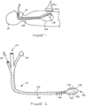
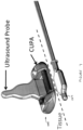
- FIG. 1 is a schematic view of a system in accordance with certain aspects of an exemplary embodiment of the invention.
- a gastric tube 110 is inserted into a patient's stomach 185, entering the patient through the head 181 (either through the patient's mouth or nose) and down through the patient's esophagus 183, with the distal end (shown generally at 120) of gastric tube 110 ultimately being positioned within the patient's stomach.
- a syringe port 116 may be provided at proximal end 112 of gastric tube 110, providing a passageway to inflate a balloon 124 at the distal end 120 of gastric tube 110.
- one or more ports may be provided at proximal end 112 of gastric tube 110 to connect external suction or insufflation devices. Such suction and insufflation ports may connect to one or more lumens that extend along the length of gastric tube 110.
- FIG 3 shows a close-up exploded view of distal end 120 of gastric tube 110 according to certain aspects of an exemplary embodiment of the invention.
- gastric tube 110 may be a generally cylindrical tube, and fenestrations 140 may be provided at the end of gastric tube 110 and aligned in axially-extending rows around the circumference of the end of gastric tube 110.
- Lumen 122 extends through gastric tube 110.
- a flexible, inflatable balloon which may be formed in varying shapes and sizes, is affixed to the end of gastric tube 110 and is in fluid communication with lumen 122 so that it may be inflated from the proximal end of gastric tube 110 with an echogenic medium, contrast agent or therapeutic agent.
- Figure 4 provides a close-up view of syringe port 116 located at the proximal end of gastric tube 110.
- syringe port 116 is attached to a syringe 118.
- Syringe 118 may be filled with any type of fluid that is capable of expanding balloon 124 with an echogenic medium, contrast agent or therapeutic agent.
- syringe 118 is filled with a non-toxic fluid that will enhance ultrasound imaging, such as by way of non-limiting example, water or saline. Gases may also be used to inflate balloon 124. While the illustrated embodiment shows syringe 118 being a removable element, in certain embodiments syringe 118 may be a permanent element, making the fluid transfer system between syringe 118 and balloon 124 a closed system.
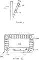
- FIG. 5a shows a schematic, cross-sectional top-down view of a coaptive ultrasound probe adaptor 200 in accordance with certain aspects of an embodiment of the invention.
- Adaptor 200 may be formed in a variety of different shapes to receive existing or yet-to-be-developed ultrasound probes.
- "ultrasound probe” is intended to refer to any hand-held device configured to provide ultrasound imaging.
- Ultrasound probe adaptor 200 includes a magnetic source, and is physically configured so as to attach to an ultrasound probe 595.
- the magnetic source comprises an electromagnet having a power source 220, a variable resistor dial 240, and a coil 230, all contained within an external housing 210.
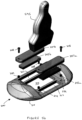
- FIG. 5b shows a close-up exploded view of a coaptive ultrasound probe adaptor 200, along with an ultrasound probe 595, according to certain aspects of a particularly preferred embodiment of the invention.
- ultrasound probe adaptor 200 includes base 210 having central cavity or opening 215 centrally located in the base 210 and extending through the entire thickness of base 210, such that ultrasound probe 595 may be placed in opening 215 and in contact with a patient's skin on which ultrasound probe adaptor 200 is positioned.
- opening 215 is sized having a width dimension that is less that the width of balloon 124 on gastric tube 110, such that the sides of the balloon 124 extend past the long side edges of opening 215 when balloon 124 is magnetically attracted to ultrasound probe adaptor 200.
- magnet receiving slots 217 are positioned at opposing sides of opening 215, and are each configured to removably receive a magnet 245a and 245b therein.
- the magnets 245a and 245b are situated in opposite orientations from one another within their respective slots in ultrasound probe adaptor 200.
- ultrasound probe adaptor 200 is configured to position magnets 245a and 245b a distance away from one another that approximately matches the distance between magnets 126 positioned in balloon 124 so as to provide for alignment of the long axes of balloon 124 and ultrasound probe adaptor 200 when the two are magnetically attracted to one another.
- a first cover plate 247a may cover the magnet receiving slot 217 that receives magnet 245a
- a second cover plate 247b may cover the magnet receiving slot 217 that receives magnet 245b.
- Each such cover plate 247a and 247b is preferably removably held over its designated receiving slot 217 with removable connectors, such as threaded bolts 248 that extend into nuts 249 that in turn are held within base 110.
- removable connectors such as threaded bolts 248 that extend into nuts 249 that in turn are held within base 110.
- magnets of varying strength may be positioned within slots 217 so as to vary the amount of magnetic attraction that will be realized between ultrasound probe adaptor 200 and balloon 124, which may be necessary for varying medical procedures and varying patient physiology (i.e., with larger tissue planes between the ultrasound probe adaptor 200 and balloon 124 requiring larger magnetic attraction and in some cases repulsion).
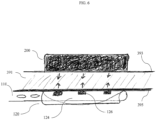
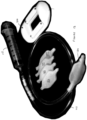
- Figure 6 shows a cross-sectional view and Figure 7 a perspective view of the coaptive ultrasound probe adaptor 200 interacting with balloon 124 through a tissue plane.
- the distal end 120 of gastric tube 110 having balloon 124 is shown in Figure 6 positioned inside of a patient's stomach, with ultrasound probe adaptor 200 positioned outside of the patient's body and in contact with the skin of the patient's abdomen.
- ultrasound probe adaptor 200 is positioned directly against the patient's skin 393, and the magnetic forces that attract balloon 124 to ultrasound probe adaptor 200 extend through the patient's skin 393, through the subcutaneous tissue 391, and through the stomach wall 395 (such tissue planes being hidden in Figure 7 for clarity).
- Magnetic members in each of ultrasound probe adaptor 200 and balloon 124 such as magnets 126, cause balloon 124 to come into contact with stomach wall 395 and to push stomach wall 395 against the subcutaneous tissue 391 of the patient's abdomen (defined as coaptation), thus easing access to balloon 124 with a needle, cannula, or other device as described in greater detail below.
- the position of magnets 126 in balloon 124 and of magnets 245a and 245b in ultrasound probe adaptor 200 may cause the balloon 124 and adaptor 200 to align their long axes with one another, and allow coordinated movement between the two.
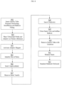
- Figure 8 is a flow diagram that depicts one non-claimed method of performing a gastrostomy using the system of the present invention. Although steps are depicted in Figure 8 as integral steps in a particular order for purposes of illustration, in other embodiments, one or more steps, or portions thereof, are performed in a different order, or overlapping in time, in series or in parallel, or are omitted, or one or more additional steps are added, or the method is changed in some combination of ways. Some of the steps are illustrated in Figures 9 through 12 .
- a gastric tube 110 configured as above is inserted through a patient's nose or mouth until the distal end 120 of the gastric tube 110 is positioned inside of the patient's stomach.
- Existing stomach contents are extracted, for example by applying suction through fenestrations 140 in the gastric tube 110.
- the stomach is insufflated, for example by using both the same or different channels and fenestrations in the gastric tube 110.
- Syringe 118 is filled with non-toxic fluid.
- ultrasound probe 595 and adaptor 200 are placed on the patient's abdomen 590 (as shown in Figure 9 ). If the ultrasound probe adaptor is provided an electromagnet, it is activated at this time.
- Ultrasound probe 595 is used to ultrasonically image the patient's internal abdomen to detect any interposed organs or large vessels positioned between the ultrasound probe adaptor 200 and the balloon 124.
- ultrasound probe adaptor 200 In the event that ultrasound probe adaptor 200 is provided an electromagnet assembly, the strength of the magnet may be adjusted using the variable resistor dial 240. Likewise, if ferromagnets are positioned in ultrasound probe adaptor 200, the strength of the magnetic force generated by ultrasound probe adaptor 200 may be modified by simply changing the magnets 245a and 245b in adaptor 200. In some cases, it may be necessary to reduce the magnetic attraction to allow for coordinated movement of the devices until a suitable entry point is identified. In other instances, it may be necessary to increase the magnetic attraction to account for excessive subcutaneous tissue. In any case, once a proper entry point is identified, the depth of the subcutaneous tissue may be measured to give the practitioner a reference point before making an incision.
- an inner needle 583 and angiocatheter 580 are inserted into the patient's stomach through the abdomen, preferably through opening 215 in adaptor 200.
- Inner needle 583 is then removed in step 807, and in step 808 (and as shown in Figure 11 ), guide wire 582 is introduced through angiocatheter 580.
- snare 132 is closed and the balloon 124 is deflated in step 809.
- gastric tube 110 is removed from the patient in step 810, and snare 132 is released in step 811 when the gastric tube is completely removed.
- Figure 12 shows the final result of the method, in which guide wire 582 extends from the patient's stomach 185, through the esophagus 183, and out through the patient's head 181.
- the proximal end 589 terminates outside of the patient's stomach.
- the distal end 587 terminates outside of the patient's nose or mouth.
- the devices of the present invention are used to introduce a percutaneous gastrostomy tube into a patient using gastropexy methods.
- steps 802 through 807 remain the same.
- one or more gastropexy anchors are inserted into the patient's stomach. Once the one or more anchors are fixated, standard gastrostomy methods follow using a guide wire placed only within the stomach.
- Figure 13 shows a kit for placing an elongate medical member, such as a conduit, within a patient's body in accordance with certain aspects of an embodiment of the invention.
- a kit preferably includes at least an ultrasound probe adaptor 200 configured as described above, a conduit 110, a syringe 118 for connection to a proximal end of conduit 110, a plurality of inflatable balloons 124 for connection to the distal end of conduit 110, and at least one magnet 126 sized for insertion into each of balloons 124.
- more than one magnet 126 is provided, with the magnets preferably having differing magnetic strengths that a practitioner may select for a particular circumstance (e.g., for tissue planes of varying thickness).
- additional elements could be provided with such a kit, including items such as feeding tubes or other supply or fluid drainage conduits, guide wires, dilators, and the like, all without departing from the spirit and scope of the instant invention.
- the present invention is applicable to devices for placing medical devices into and manipulating such medical devices within patients, particularly through ultrasound-guided placement and manipulation.
- the devices can be made in industry and practiced in the medical device field.
Landscapes
- Health & Medical Sciences (AREA)
- Life Sciences & Earth Sciences (AREA)
- Animal Behavior & Ethology (AREA)
- General Health & Medical Sciences (AREA)
- Public Health (AREA)
- Veterinary Medicine (AREA)
- Heart & Thoracic Surgery (AREA)
- Biomedical Technology (AREA)
- Engineering & Computer Science (AREA)
- Biophysics (AREA)
- Pulmonology (AREA)
- Pathology (AREA)
- Molecular Biology (AREA)
- Radiology & Medical Imaging (AREA)
- Physics & Mathematics (AREA)
- Nuclear Medicine, Radiotherapy & Molecular Imaging (AREA)
- Surgery (AREA)
- Medical Informatics (AREA)
- Hematology (AREA)
- Otolaryngology (AREA)
- Anesthesiology (AREA)
- Media Introduction/Drainage Providing Device (AREA)
- Ultra Sonic Daignosis Equipment (AREA)
- Medical Preparation Storing Or Oral Administration Devices (AREA)
- Surgical Instruments (AREA)
Claims (15)
- Appareil, comprenant :un tube (110) présentant une extrémité distale (120), une extrémité proximale (112), et une lumière (122) s'étendant à travers celui-ci, l'extrémité distale (120) étant conçue pour être disposée à l'intérieur de l'estomac d'un patient par le biais de l'œsophage du patient ;un ballonnet (124) accouplé à l'extrémité distale (120) du tube et présentant une paroi de ballonnet délimitant un intérieur en communication fluidique avec la lumière, le ballonnet (124) étant gonflable avec un fluide distribué par le biais de la lumière pour délimiter un espace échogène ;un aimant (126) disposé dans la lumière du tube et disposé entièrement à l'intérieur du ballonnet, une position du ballonnet et de l'extrémité distale du tube à l'intérieur de l'estomac du patient pouvant être contrôlée par le biais de l'attraction magnétique entre l'aimant et une source magnétique externe disposée à l'extérieur du patient de telle sorte que le ballonnet pousse la paroi stomacale du patient contre le tissu sous-cutané de l'abdomen du patient.
- Appareil selon la revendication 1, le ballonnet étant conçu pour recevoir un fil-guide par le biais de la peau et de la paroi stomacale d'un patient.
- Appareil selon la revendication 1, comprenant en outre une source magnétique externe conçue pour contrôler la position du ballonnet et de l'extrémité distale du tube par attraction magnétique avec l'aimant.
- Appareil selon la revendication 1, dans lequel l'aimant est un premier aimant, comprenant en outre un deuxième aimant couplé à l'une des extrémités distales du tube et du ballonnet.
- Appareil selon la revendication 4, dans lequel le deuxième aimant est positionné à l'intérieur du ballonnet.
- Appareil selon la revendication 1, comprenant en outre un adaptateur de sonde à ultrasons présentant une ouverture conçue pour recevoir une sonde à ultrasons dans celui-ci et pour maintenir la sonde à ultrasons en contact avec la peau du patient, une source magnétique externe étant couplée à l'adaptateur de sonde à ultrasons.
- Appareil selon la revendication 4, dans lequel le premier aimant est positionné sur un premier côté du ballonnet et le deuxième aimant est positionné sur un second côté du ballonnet, le premier aimant et le deuxième aimant étant conçus pour l'attraction magnétique avec une source magnétique externe, la source magnétique externe comportant un troisième aimant et un quatrième aimant.
- Appareil selon la revendication 7, dans lequel les premier et deuxième aimants sont espacés l'un de l'autre d'une distance égale à une distance qui sépare les troisième et quatrième aimants l'un de l'autre.
- Appareil selon la revendication 3, dans lequel l'aimant et la source magnétique externe ont des champs magnétiques qui sont orientés de sorte à attirer l'extrémité distale du tube vers la source magnétique externe.
- Appareil selon la revendication 1, comprenant en outre :une ligne de collet disposée dans la lumière et s'étendant à travers celle-ci et présentant une extrémité proximale disposée proximalement à l'extrémité proximale du tube et une extrémité distale disposée dans le ballonnet ; etun collet accouplé à l'extrémité distale de la ligne de collet, disposé dans le ballonnet, et conçu pour entrer en prise avec, et retenir, l'extrémité distale d'un fil-guide reçu dans l'intérieur du ballonnet de sorte que l'extrémité proximale du fil-guide puisse être retirée du patient en retirant l'extrémité proximale du tube du patient par le biais de l'œsophage du patient.
- Kit comprenant :l'appareil selon la revendication 1 ; etdans lequel le ballonnet fait partie d'une pluralité de ballonnets conçus pour être fixés à l'extrémité distale du tube, le kit comportant la pluralité de ballonnets.
- Kit selon la revendication 11, comprenant en outre un adaptateur de sonde à ultrasons présentant une ouverture conçue pour recevoir une sonde à ultrasons dans celui-ci et pour maintenir la sonde à ultrasons en contact avec la peau du patient et une source magnétique externe couplée de manière amovible à l'adaptateur de sonde à ultrasons.
- Kit selon la revendication 11, dans lequel l'aimant est un premier aimant, et comprenant en outre un deuxième aimant dimensionné pour être inséré à l'intérieur de chacun des ballonnets de la pluralité de ballonnets.
- Kit selon la revendication 13, dans lequel le premier aimant est positionné sur un premier côté du ballonnet et le deuxième aimant est positionné sur un second côté du ballonnet, comprenant en outre une source magnétique externe comportant un troisième aimant et un quatrième aimant.
- Kit selon la revendication 11, comprenant en outre une seringue conçue pour être fixée à l'extrémité proximale du tube.
Applications Claiming Priority (3)
| Application Number | Priority Date | Filing Date | Title |
|---|---|---|---|
| US201361814516P | 2013-04-22 | 2013-04-22 | |
| PCT/US2014/034950 WO2014176236A1 (fr) | 2013-04-22 | 2014-04-22 | Dispositifs ultrasonores de coaptation et méthodes d'utilisation |
| EP14788472.0A EP2988815B1 (fr) | 2013-04-22 | 2014-04-22 | Dispositifs ultrasonores de coaptation |
Related Parent Applications (1)
| Application Number | Title | Priority Date | Filing Date |
|---|---|---|---|
| EP14788472.0A Division EP2988815B1 (fr) | 2013-04-22 | 2014-04-22 | Dispositifs ultrasonores de coaptation |
Publications (2)
| Publication Number | Publication Date |
|---|---|
| EP3444002A1 EP3444002A1 (fr) | 2019-02-20 |
| EP3444002B1 true EP3444002B1 (fr) | 2025-06-04 |
Family
ID=51792333
Family Applications (2)
| Application Number | Title | Priority Date | Filing Date |
|---|---|---|---|
| EP14788472.0A Active EP2988815B1 (fr) | 2013-04-22 | 2014-04-22 | Dispositifs ultrasonores de coaptation |
| EP18177361.5A Active EP3444002B1 (fr) | 2013-04-22 | 2014-04-22 | Dispositifs à ultrasons de coaptation |
Family Applications Before (1)
| Application Number | Title | Priority Date | Filing Date |
|---|---|---|---|
| EP14788472.0A Active EP2988815B1 (fr) | 2013-04-22 | 2014-04-22 | Dispositifs ultrasonores de coaptation |
Country Status (4)
| Country | Link |
|---|---|
| US (5) | US10383595B2 (fr) |
| EP (2) | EP2988815B1 (fr) |
| JP (3) | JP6641264B2 (fr) |
| WO (1) | WO2014176236A1 (fr) |
Families Citing this family (17)
| Publication number | Priority date | Publication date | Assignee | Title |
|---|---|---|---|---|
| US10383595B2 (en) | 2013-04-22 | 2019-08-20 | University Of Maryland, Baltimore | Coaptation ultrasound devices and methods of use |
| KR20160046670A (ko) * | 2014-10-21 | 2016-04-29 | 삼성전자주식회사 | 영상 진단 보조 장치 및 방법 |
| US10143526B2 (en) * | 2015-11-30 | 2018-12-04 | Auris Health, Inc. | Robot-assisted driving systems and methods |
| JP2017169994A (ja) * | 2016-03-25 | 2017-09-28 | Hoya株式会社 | 内視鏡先端位置特定システム |
| WO2017176881A1 (fr) | 2016-04-05 | 2017-10-12 | University Of Maryland, Baltimore | Procédé et appareil pour une gastrostomie à ultrasons de coaptation |
| CN107551380B (zh) * | 2016-06-30 | 2020-06-09 | 上海交通大学医学院附属第九人民医院 | 一种盘状胃造瘘管拔管装置及拔管方法 |
| WO2019210170A1 (fr) | 2018-04-27 | 2019-10-31 | Coaptech Llc | Systèmes, appareil et procédés pour placer un fil-guide pour un tube de gastrostomie |
| CN113423338B (zh) * | 2018-05-04 | 2024-12-03 | 科普科技股份有限公司 | 用于越过身体管腔中的分叉递送医疗装置的系统、装置和方法 |
| CA3122496A1 (fr) * | 2018-06-01 | 2019-12-05 | CoapTech, Inc. | Systemes, appareils et procedes pour realiser une tracheostomie percutanee |
| EP3946087B1 (fr) | 2019-04-04 | 2024-04-24 | Transmed7, LLC | Dispositifs d'excision |
| US11690978B2 (en) * | 2019-07-03 | 2023-07-04 | Medtronic, Inc. | Catheter for ultrasound-guided delivery |
| US12582434B1 (en) | 2020-04-06 | 2026-03-24 | Transmed7 Llc | Excisional devices and methods |
| AU2022282370A1 (en) * | 2021-05-27 | 2023-12-14 | Becton, Dickinson And Company | Method of repositioning a catheter distal tip and related systems |
| WO2023023360A1 (fr) * | 2021-08-19 | 2023-02-23 | CoapTech, Inc. | Systèmes, appareil et méthodes pour placer un fil-guide pour un tube de jéjunostomie |
| EP4440673A4 (fr) * | 2021-12-03 | 2025-11-12 | Coaptech Inc | Systèmes, appareil et méthodes de traitement des espaces pleural et péritonéal |
| CN115474966B (zh) * | 2022-09-30 | 2023-06-02 | 上海市东方医院(同济大学附属东方医院) | 一种带有超声探头的鼻胃管 |
| CN121288171B (zh) * | 2025-12-11 | 2026-03-17 | 中国人民解放军总医院第五医学中心 | 用于以血管内的方式将药液导入体内的药液导入装置 |
Family Cites Families (108)
| Publication number | Priority date | Publication date | Assignee | Title |
|---|---|---|---|---|
| US3961632A (en) | 1974-12-13 | 1976-06-08 | Moossun Mohamed H | Stomach intubation and catheter placement system |
| US4403612A (en) | 1980-10-20 | 1983-09-13 | Fogarty Thomas J | Dilatation method |
| US5058580A (en) | 1988-05-11 | 1991-10-22 | Hazard Patrick B | Percutaneous tracheostomy tube |
| US4932959A (en) | 1988-12-01 | 1990-06-12 | Advanced Cardiovascular Systems, Inc. | Vascular catheter with releasably secured guidewire |
| US5681260A (en) * | 1989-09-22 | 1997-10-28 | Olympus Optical Co., Ltd. | Guiding apparatus for guiding an insertable body within an inspected object |
| US5154387A (en) | 1990-05-31 | 1992-10-13 | Syncromed Corporation | Method and apparatus for esophageal pacing |
| US5265622A (en) | 1990-10-25 | 1993-11-30 | C. R. Bard, Inc. | Guidewire having radially expandable member and method for guiding and advancing a catheter using the same |
| US5269291A (en) | 1990-12-10 | 1993-12-14 | Coraje, Inc. | Miniature ultrasonic transducer for plaque ablation |
| US5084014A (en) * | 1990-12-13 | 1992-01-28 | Applied Medical Technology, Inc. | Package for initial placement of low profile gastrostomy device and method of placement |
| US5112310A (en) | 1991-02-06 | 1992-05-12 | Grobe James L | Apparatus and methods for percutaneous endoscopic gastrostomy |
| US5329872A (en) | 1991-08-30 | 1994-07-19 | Wright Howard W | All weather safety whistle and sound generator |
| AU677286B2 (en) | 1993-01-07 | 1997-04-17 | Ballard Medical Products | Gastrostomy catheter system |
| US5497782A (en) | 1994-04-28 | 1996-03-12 | Medtronic, Inc. | Lockable guidewire |
| JPH0889583A (ja) * | 1994-09-28 | 1996-04-09 | Fuji Syst Kk | 医療用カテーテルの誘導方法 |
| JPH0889582A (ja) * | 1994-09-28 | 1996-04-09 | Fuji Syst Kk | 医療用カテーテル及びその誘導方法 |
| JPH08117232A (ja) * | 1994-10-24 | 1996-05-14 | Olympus Optical Co Ltd | 穿刺具 |
| US5431640A (en) | 1994-11-09 | 1995-07-11 | The Medical Center Of Central Georgia | Method and apparatus for duodenal intubation of a patient |
| US5653230A (en) | 1996-01-19 | 1997-08-05 | Cook Incorporated | Percutaneous balloon dilational tracheostomy tube |
| US5669380A (en) | 1996-04-26 | 1997-09-23 | New England Medical Center Hospitals, Inc. | Laryngeal bypass |
| ES2219770T3 (es) | 1996-06-17 | 2004-12-01 | Becton, Dickinson And Company | Tubo medico para insercion y deteccion dentro del cuerpo de un paciente. |
| GB2318297B (en) | 1996-10-16 | 2000-04-12 | Smiths Industries Plc | A tracheal shield assembly |
| US6058323A (en) | 1996-11-05 | 2000-05-02 | Lemelson; Jerome | System and method for treating select tissue in a living being |
| JPH1156852A (ja) | 1997-08-25 | 1999-03-02 | Olympus Optical Co Ltd | 超音波プローブ |
| US6015414A (en) | 1997-08-29 | 2000-01-18 | Stereotaxis, Inc. | Method and apparatus for magnetically controlling motion direction of a mechanically pushed catheter |
| US7066924B1 (en) | 1997-11-12 | 2006-06-27 | Stereotaxis, Inc. | Method of and apparatus for navigating medical devices in body lumens by a guide wire with a magnetic tip |
| EP0980691B1 (fr) | 1998-01-14 | 2004-11-10 | Sumitomo Bakelite Co., Ltd. | Catheter a ballonnet pour ponctions et instrument a usage medical pour introduction de tube utilisant ce catheter |
| US6173199B1 (en) | 1998-05-05 | 2001-01-09 | Syncro Medical Innovations, Inc. | Method and apparatus for intubation of a patient |
| US6428551B1 (en) | 1999-03-30 | 2002-08-06 | Stereotaxis, Inc. | Magnetically navigable and/or controllable device for removing material from body lumens and cavities |
| US6126647A (en) | 1999-05-17 | 2000-10-03 | Hermetic Switch, Inc. | Magnetically guided catheter with sensor |
| US6702804B1 (en) | 1999-10-04 | 2004-03-09 | Stereotaxis, Inc. | Method for safely and efficiently navigating magnetic devices in the body |
| US7033373B2 (en) | 2000-11-03 | 2006-04-25 | Satiety, Inc. | Method and device for use in minimally invasive placement of space-occupying intragastric devices |
| JP4578740B2 (ja) * | 2001-09-21 | 2010-11-10 | オリンパス株式会社 | カプセル型医療装置 |
| US20060247575A1 (en) * | 2001-12-21 | 2006-11-02 | Richard Cartledge | Balloon cannulae |
| JP3826045B2 (ja) | 2002-02-07 | 2006-09-27 | オリンパス株式会社 | 内視鏡用フード |
| US6651665B1 (en) | 2002-02-19 | 2003-11-25 | Ibionics, Inc. | Rotating magnetic guide intubation system |
| US6701918B2 (en) | 2002-02-19 | 2004-03-09 | Ibionics Corporation | Magnetically guided device for insertion through a nasal passageway |
| AU2003295741A1 (en) | 2002-11-18 | 2004-06-15 | Stereotaxis, Inc. | Magnetically navigable balloon catheters |
| US7036510B2 (en) | 2003-04-28 | 2006-05-02 | Cook Critical Care Incorporated | Percutaneous tracheostomy balloon apparatus |
| DE102004009318B4 (de) | 2004-02-26 | 2006-05-04 | Siemens Ag | Vorrichtung zur wiederholten semi-invasiven Abrasion von Veränderungen an den Wänden von Hohlorganen |
| US7769428B2 (en) | 2004-06-29 | 2010-08-03 | Stereotaxis, Inc. | Navigation of remotely actuable medical device using control variable and length |
| EP1804668B1 (fr) * | 2004-10-18 | 2012-05-23 | Mobile Robotics Sweden AB | Robot d'examen ultrasonore |
| EP1858417A1 (fr) | 2005-02-28 | 2007-11-28 | Wilson-Cook Medical Inc. | Marqueurs échogènes sur des dispositifs médicaux gi |
| US8777967B2 (en) | 2005-06-09 | 2014-07-15 | Xlumena, Inc. | Methods and devices for anchoring to tissue |
| JP4746359B2 (ja) | 2005-06-20 | 2011-08-10 | オリンパスメディカルシステムズ株式会社 | 内視鏡用処置具 |
| US8226637B2 (en) | 2005-11-01 | 2012-07-24 | Japan Electel, Inc. | Balloon catheter system |
| US20090187164A1 (en) | 2006-05-03 | 2009-07-23 | Rowe Philip S | Nasogastric tube placement and monitoring system |
| US20080045863A1 (en) | 2006-08-17 | 2008-02-21 | Ethicon Endo-Surgery, Inc. | Guidewire structure including a medical guidewire |
| CN103785096B (zh) | 2007-02-08 | 2016-09-14 | C.R.巴德有限公司 | 形状记忆医疗器械及其生产方法 |
| JP2008284136A (ja) * | 2007-05-17 | 2008-11-27 | Shimadzu Corp | 超音波プローブ用アタッチメント及び超音波プローブ |
| WO2009006616A1 (fr) * | 2007-07-03 | 2009-01-08 | Irvine Biomedical, Inc. | Cathéter magnétiquement guidé |
| WO2009029869A2 (fr) | 2007-08-30 | 2009-03-05 | Syncro Medical Innovations, Inc. | Cathéter guidé comportant un guide magnétique amovible |
| US7879056B2 (en) | 2007-10-11 | 2011-02-01 | Keith Butterfield | Pleurabrade device |
| US9521961B2 (en) | 2007-11-26 | 2016-12-20 | C. R. Bard, Inc. | Systems and methods for guiding a medical instrument |
| US8100860B2 (en) | 2007-12-06 | 2012-01-24 | Abbott Laboratories | Device and method for treating vulnerable plaque |
| US7713215B2 (en) | 2008-01-31 | 2010-05-11 | Shriver Edgar L | Steering, piercing, anchoring, distending extravascular guidewire |
| JP5101359B2 (ja) | 2008-03-26 | 2012-12-19 | テルモ株式会社 | ガイドワイヤ導入具及びガイドワイヤ導入具セット |
| JP2012501689A (ja) * | 2008-09-02 | 2012-01-26 | シンクロ メディカル イノベーションズ, インコーポレイテッド | カテーテル誘導のための磁気装置および使用方法 |
| RU2506056C2 (ru) | 2008-09-18 | 2014-02-10 | Аккларент, Инк. | Способы и аппарат для лечения заболеваний уха, горла, носа |
| WO2010036721A2 (fr) | 2008-09-24 | 2010-04-01 | Interlace Medical, Inc. | Systèmes, procédés et dispositifs permettant d'utiliser un milieu liquide pour détendre un organe creux |
| US8437833B2 (en) | 2008-10-07 | 2013-05-07 | Bard Access Systems, Inc. | Percutaneous magnetic gastrostomy |
| US8828031B2 (en) * | 2009-01-12 | 2014-09-09 | Ethicon Endo-Surgery, Inc. | Apparatus for forming an anastomosis |
| CL2009000279A1 (es) | 2009-02-06 | 2009-08-14 | Biotech Innovations Ltda | Sistema de guia y traccion remota para cirugia mini-invasiva, que comprende: al menos una endopinza quirurgica y desprendible con medios de enganches y una porcion de material ferro magnaetico, una guia de introduccion de forma cilindrica, un mecanismo de desprendimiento, y al menos un medio de traccion remota con iman. |
| WO2010129327A1 (fr) | 2009-05-05 | 2010-11-11 | Tufts Medical Center | Dispositif d'intubation trachéale |
| ATE553805T1 (de) | 2009-07-31 | 2012-05-15 | Safetrach Ab | Dilatatoreinheit und vorrichtung zur erleichterung einer tracheostomie |
| CN102686264A (zh) * | 2009-10-27 | 2012-09-19 | 雪松-西奈医疗中心 | 用于具有增强的细胞滞留的靶向细胞递送的外部磁力 |
| US8677990B2 (en) | 2010-04-28 | 2014-03-25 | Syncro Medical Innovations, Inc. | Endo-tracheal intubation device with adjustably bendable stylet |
| CN102309809B (zh) * | 2010-07-09 | 2013-11-20 | 同济大学 | 造口术系统 |
| US9332990B2 (en) | 2010-12-30 | 2016-05-10 | Wake Forest University Health Sciences | Ureter to ileal conduit anastomosis using magnetic compression and related delivery devices and methods |
| GB2494113B (en) | 2011-08-25 | 2013-07-17 | Cook Medical Technologies Llc | Medical balloon and balloon catheter assembly |
| US20130047993A1 (en) | 2011-08-31 | 2013-02-28 | Nellcor Puritan Bennett Llc | Tracheal tube having a flange with a variable volume |
| GB2494395B (en) | 2011-09-02 | 2014-01-08 | Cook Medical Technologies Llc | Ultrasonically visible scoring balloon |
| GB2494864B (en) | 2011-09-16 | 2014-02-26 | Cook Medical Technologies Llc | Ultrasonically visible balloon catheter assembly and method of imaging a medical balloon |
| ITMI20111820A1 (it) | 2011-10-06 | 2013-04-07 | Enrico Giustiniano | Dispositivo di ausilio all'intubazione oro-tracheale |
| JP5885487B2 (ja) | 2011-12-09 | 2016-03-15 | オリンパス株式会社 | 誘導型医療システム |
| US8834370B2 (en) | 2011-12-15 | 2014-09-16 | Cook Medical Technologies Llc | Ultrasonic percutaneous enteral feeding tube |
| EP2604191A1 (fr) | 2011-12-15 | 2013-06-19 | University College Cork | Accouplement magnétique permettant d'améliorer la mise en place des tubes d'alimentation gastro-entérale et tubes de colostomie |
| US9936896B2 (en) * | 2012-01-12 | 2018-04-10 | Siemens Medical Solutions Usa, Inc. | Active system and method for imaging with an intra-patient probe |
| CN104093361B (zh) * | 2012-01-25 | 2018-09-04 | 皇家飞利浦有限公司 | 一种牙科金属伪影减少方法及成像系统 |
| EP2879595B1 (fr) | 2012-08-03 | 2019-04-10 | Muffin Incorporated | Cathéter à ballonnet suintant avec élément à ultrasons |
| US9713578B2 (en) | 2012-12-20 | 2017-07-25 | Sabry Gabriel | Feeding tube with inflatable balloon component |
| US9492644B2 (en) * | 2012-12-21 | 2016-11-15 | Avent, Inc. | Dilation device for placing catheter tubes |
| US8827953B2 (en) | 2013-01-15 | 2014-09-09 | Krishna Rocha-Singh | Apparatus and method for delivering intraluminal therapy |
| US9339285B2 (en) | 2013-03-12 | 2016-05-17 | Levita Magnetics International Corp. | Grasper with magnetically-controlled positioning |
| US10010370B2 (en) | 2013-03-14 | 2018-07-03 | Levita Magnetics International Corp. | Magnetic control assemblies and systems therefor |
| US10383595B2 (en) | 2013-04-22 | 2019-08-20 | University Of Maryland, Baltimore | Coaptation ultrasound devices and methods of use |
| WO2015021133A2 (fr) * | 2013-08-06 | 2015-02-12 | Cook Medical Technologies Llc | Système et procédé pour connexions percutanées externes |
| JP2015061550A (ja) | 2013-09-21 | 2015-04-02 | 住友ベークライト株式会社式会社 | 内視鏡用ガイドチューブ |
| EP3096673B1 (fr) | 2014-01-21 | 2025-02-19 | Levita Magnetics International Corp. | Moyens de préhension laparoscopique et systèmes associés |
| US20150238729A1 (en) | 2014-02-24 | 2015-08-27 | Mark Lynn Jenson | Cardiac Access Catheter, System, and Method |
| US9918618B2 (en) | 2014-08-08 | 2018-03-20 | Wm & Dg, Inc. | Medical devices and methods of placement |
| US20160279393A1 (en) | 2015-03-25 | 2016-09-29 | Covidien Lp | Guidewire retrieval catheter |
| JP6564639B2 (ja) | 2015-07-16 | 2019-08-21 | テルモ株式会社 | 止血デバイス |
| WO2017176881A1 (fr) | 2016-04-05 | 2017-10-12 | University Of Maryland, Baltimore | Procédé et appareil pour une gastrostomie à ultrasons de coaptation |
| WO2017216650A1 (fr) | 2016-06-14 | 2017-12-21 | Barkhordari Khosro | Tube endotrachéal pour trachéotomie par dilatation percutanée et bronchoscopie |
| EP3461256A4 (fr) | 2016-06-30 | 2019-09-11 | Tel Hashomer Medical Research Infrastructure and Services Ltd. | Appareil et procédé pour accéder à l'aorte |
| US11278189B2 (en) | 2017-01-12 | 2022-03-22 | Endostart S.r.l. | Endoscopic guide including anchoring head that accommodates a magnetic or ferromagnetic agent |
| WO2019210170A1 (fr) | 2018-04-27 | 2019-10-31 | Coaptech Llc | Systèmes, appareil et procédés pour placer un fil-guide pour un tube de gastrostomie |
| CN113423338B (zh) | 2018-05-04 | 2024-12-03 | 科普科技股份有限公司 | 用于越过身体管腔中的分叉递送医疗装置的系统、装置和方法 |
| CA3122496A1 (fr) | 2018-06-01 | 2019-12-05 | CoapTech, Inc. | Systemes, appareils et procedes pour realiser une tracheostomie percutanee |
| US20230191061A1 (en) | 2018-06-01 | 2023-06-22 | CoapTech, Inc. | Systems, apparatus, and methods for performing a percutaneous tracheostomy |
| US20210275766A1 (en) | 2018-06-01 | 2021-09-09 | Coaptech Llc | Systems, apparatus, and methods for performing a percutaneous tracheostomy |
| TR201808066A2 (tr) | 2018-06-06 | 2018-07-23 | Ykk Saglik Hizmetleri Ltd Sti | KOAH PEELİNG BALON KATATER SİSTEMİ ve UYGULAMA METODU |
| WO2021051051A1 (fr) | 2019-09-12 | 2021-03-18 | Free Flow Medical, Inc. | Dispositifs, procédés et systèmes pour traiter la bronchite chronique |
| JP7761599B2 (ja) | 2020-06-18 | 2025-10-28 | コープテック,インコーポレイテッド | 経皮的気管切開を実施するためのシステム、装置及び方法 |
| US20210393911A1 (en) | 2020-06-23 | 2021-12-23 | [AI]rway, Inc. | Smart endotracheal tube |
| WO2023023360A1 (fr) | 2021-08-19 | 2023-02-23 | CoapTech, Inc. | Systèmes, appareil et méthodes pour placer un fil-guide pour un tube de jéjunostomie |
| EP4440673A4 (fr) | 2021-12-03 | 2025-11-12 | Coaptech Inc | Systèmes, appareil et méthodes de traitement des espaces pleural et péritonéal |
| WO2023133552A2 (fr) | 2022-01-07 | 2023-07-13 | CoapTech, Inc. | Systèmes, appareil et procédés de placement et/ou de confirmation d'un emplacement d'une extrémité d'un tube nasogastrique ou orogastrique |
-
2014
- 2014-04-22 US US14/785,366 patent/US10383595B2/en active Active
- 2014-04-22 EP EP14788472.0A patent/EP2988815B1/fr active Active
- 2014-04-22 WO PCT/US2014/034950 patent/WO2014176236A1/fr not_active Ceased
- 2014-04-22 EP EP18177361.5A patent/EP3444002B1/fr active Active
- 2014-04-22 JP JP2016510734A patent/JP6641264B2/ja active Active
-
2017
- 2017-11-10 US US15/809,665 patent/US10219778B2/en active Active
-
2019
- 2019-08-19 US US16/544,518 patent/US20200214661A1/en not_active Abandoned
- 2019-12-27 JP JP2019238125A patent/JP7089293B2/ja active Active
-
2022
- 2022-06-03 JP JP2022091041A patent/JP7565092B2/ja active Active
- 2022-09-15 US US17/945,971 patent/US11986340B2/en active Active
-
2024
- 2024-04-04 US US18/627,397 patent/US20250090133A1/en not_active Abandoned
Also Published As
| Publication number | Publication date |
|---|---|
| EP2988815B1 (fr) | 2018-06-13 |
| US20230181151A1 (en) | 2023-06-15 |
| EP2988815A4 (fr) | 2017-01-18 |
| JP2020062448A (ja) | 2020-04-23 |
| EP2988815A1 (fr) | 2016-03-02 |
| JP7565092B2 (ja) | 2024-10-10 |
| JP6641264B2 (ja) | 2020-02-05 |
| JP2022122971A (ja) | 2022-08-23 |
| US10219778B2 (en) | 2019-03-05 |
| US20160081652A1 (en) | 2016-03-24 |
| WO2014176236A1 (fr) | 2014-10-30 |
| JP7089293B2 (ja) | 2022-06-22 |
| US10383595B2 (en) | 2019-08-20 |
| JP2016522021A (ja) | 2016-07-28 |
| US20250090133A1 (en) | 2025-03-20 |
| US11986340B2 (en) | 2024-05-21 |
| US20180078234A1 (en) | 2018-03-22 |
| US20200214661A1 (en) | 2020-07-09 |
| EP3444002A1 (fr) | 2019-02-20 |
Similar Documents
| Publication | Publication Date | Title |
|---|---|---|
| US11986340B2 (en) | Coaptation ultrasound devices and methods of use | |
| CN103877666B (zh) | 具有可膨胀气囊构件的饲管 | |
| US6090073A (en) | Direct percutaneous endoscopic jejunostomy method and apparatus | |
| US20230047272A1 (en) | Method and apparatus for coaptive ultrasound gastrostomy | |
| JP2017520377A (ja) | 接続可能カテーテル | |
| JP2012501689A (ja) | カテーテル誘導のための磁気装置および使用方法 | |
| JP7421503B2 (ja) | 経皮的気管切開を実施するためのシステム、装置及び方法 | |
| CA2632035C (fr) | Sonde peg et peg-j a fil court | |
| CN110710952A (zh) | 经肛门向回盲瓣的深度植入器械及其植入方法 | |
| US20240415741A1 (en) | Systems, apparatus, and methods for placing a guidewire for a jejunostomy tube | |
| PT1547639E (pt) | Cateter de balão com bolsa de posicionamento | |
| WO2013087841A1 (fr) | Couplage magnétique pour l'amélioration du placement de tubes d'alimentation gastro-entérale et de tubes de colostomie | |
| JPH0889583A (ja) | 医療用カテーテルの誘導方法 | |
| WO2023129065A1 (fr) | Ensemble de gastrostomie endoscopique percutanée avec ballonnet | |
| CA1327501C (fr) | Catheter et methode et instrument pour sa mise en place dans un organe du tractus gastro-intestinal | |
| CN112915032A (zh) | 一种体外磁力引导下的空肠管及其操作方法 |
Legal Events
| Date | Code | Title | Description |
|---|---|---|---|
| PUAI | Public reference made under article 153(3) epc to a published international application that has entered the european phase |
Free format text: ORIGINAL CODE: 0009012 |
|
| STAA | Information on the status of an ep patent application or granted ep patent |
Free format text: STATUS: THE APPLICATION HAS BEEN PUBLISHED |
|
| AC | Divisional application: reference to earlier application |
Ref document number: 2988815 Country of ref document: EP Kind code of ref document: P |
|
| AK | Designated contracting states |
Kind code of ref document: A1 Designated state(s): AL AT BE BG CH CY CZ DE DK EE ES FI FR GB GR HR HU IE IS IT LI LT LU LV MC MK MT NL NO PL PT RO RS SE SI SK SM TR |
|
| STAA | Information on the status of an ep patent application or granted ep patent |
Free format text: STATUS: REQUEST FOR EXAMINATION WAS MADE |
|
| 17P | Request for examination filed |
Effective date: 20190820 |
|
| RBV | Designated contracting states (corrected) |
Designated state(s): AL AT BE BG CH CY CZ DE DK EE ES FI FR GB GR HR HU IE IS IT LI LT LU LV MC MK MT NL NO PL PT RO RS SE SI SK SM TR |
|
| GRAP | Despatch of communication of intention to grant a patent |
Free format text: ORIGINAL CODE: EPIDOSNIGR1 |
|
| STAA | Information on the status of an ep patent application or granted ep patent |
Free format text: STATUS: GRANT OF PATENT IS INTENDED |
|
| INTG | Intention to grant announced |
Effective date: 20240516 |
|
| RIN1 | Information on inventor provided before grant (corrected) |
Inventor name: TROPELLO, STEVEN, P |
|
| GRAJ | Information related to disapproval of communication of intention to grant by the applicant or resumption of examination proceedings by the epo deleted |
Free format text: ORIGINAL CODE: EPIDOSDIGR1 |
|
| STAA | Information on the status of an ep patent application or granted ep patent |
Free format text: STATUS: REQUEST FOR EXAMINATION WAS MADE |
|
| GRAP | Despatch of communication of intention to grant a patent |
Free format text: ORIGINAL CODE: EPIDOSNIGR1 |
|
| STAA | Information on the status of an ep patent application or granted ep patent |
Free format text: STATUS: GRANT OF PATENT IS INTENDED |
|
| INTC | Intention to grant announced (deleted) | ||
| INTG | Intention to grant announced |
Effective date: 20241217 |
|
| GRAS | Grant fee paid |
Free format text: ORIGINAL CODE: EPIDOSNIGR3 |
|
| GRAA | (expected) grant |
Free format text: ORIGINAL CODE: 0009210 |
|
| STAA | Information on the status of an ep patent application or granted ep patent |
Free format text: STATUS: THE PATENT HAS BEEN GRANTED |
|
| AC | Divisional application: reference to earlier application |
Ref document number: 2988815 Country of ref document: EP Kind code of ref document: P |
|
| AK | Designated contracting states |
Kind code of ref document: B1 Designated state(s): AL AT BE BG CH CY CZ DE DK EE ES FI FR GB GR HR HU IE IS IT LI LT LU LV MC MK MT NL NO PL PT RO RS SE SI SK SM TR |
|
| REG | Reference to a national code |
Ref country code: GB Ref legal event code: FG4D |
|
| REG | Reference to a national code |
Ref country code: CH Ref legal event code: EP |
|
| P01 | Opt-out of the competence of the unified patent court (upc) registered |
Free format text: CASE NUMBER: APP_23078/2025 Effective date: 20250514 |
|
| REG | Reference to a national code |
Ref country code: DE Ref legal event code: R096 Ref document number: 602014092013 Country of ref document: DE |
|
| REG | Reference to a national code |
Ref country code: IE Ref legal event code: FG4D |
|
| REG | Reference to a national code |
Ref country code: NL Ref legal event code: MP Effective date: 20250604 |
|
| PG25 | Lapsed in a contracting state [announced via postgrant information from national office to epo] |
Ref country code: ES Free format text: LAPSE BECAUSE OF FAILURE TO SUBMIT A TRANSLATION OF THE DESCRIPTION OR TO PAY THE FEE WITHIN THE PRESCRIBED TIME-LIMIT Effective date: 20250604 Ref country code: FI Free format text: LAPSE BECAUSE OF FAILURE TO SUBMIT A TRANSLATION OF THE DESCRIPTION OR TO PAY THE FEE WITHIN THE PRESCRIBED TIME-LIMIT Effective date: 20250604 |
|
| REG | Reference to a national code |
Ref country code: LT Ref legal event code: MG9D |
|
| PG25 | Lapsed in a contracting state [announced via postgrant information from national office to epo] |
Ref country code: NO Free format text: LAPSE BECAUSE OF FAILURE TO SUBMIT A TRANSLATION OF THE DESCRIPTION OR TO PAY THE FEE WITHIN THE PRESCRIBED TIME-LIMIT Effective date: 20250904 Ref country code: GR Free format text: LAPSE BECAUSE OF FAILURE TO SUBMIT A TRANSLATION OF THE DESCRIPTION OR TO PAY THE FEE WITHIN THE PRESCRIBED TIME-LIMIT Effective date: 20250905 |
|
| PG25 | Lapsed in a contracting state [announced via postgrant information from national office to epo] |
Ref country code: PL Free format text: LAPSE BECAUSE OF FAILURE TO SUBMIT A TRANSLATION OF THE DESCRIPTION OR TO PAY THE FEE WITHIN THE PRESCRIBED TIME-LIMIT Effective date: 20250604 |
|
| PG25 | Lapsed in a contracting state [announced via postgrant information from national office to epo] |
Ref country code: BG Free format text: LAPSE BECAUSE OF FAILURE TO SUBMIT A TRANSLATION OF THE DESCRIPTION OR TO PAY THE FEE WITHIN THE PRESCRIBED TIME-LIMIT Effective date: 20250604 |
|
| PG25 | Lapsed in a contracting state [announced via postgrant information from national office to epo] |
Ref country code: HR Free format text: LAPSE BECAUSE OF FAILURE TO SUBMIT A TRANSLATION OF THE DESCRIPTION OR TO PAY THE FEE WITHIN THE PRESCRIBED TIME-LIMIT Effective date: 20250604 |
|
| PG25 | Lapsed in a contracting state [announced via postgrant information from national office to epo] |
Ref country code: RS Free format text: LAPSE BECAUSE OF FAILURE TO SUBMIT A TRANSLATION OF THE DESCRIPTION OR TO PAY THE FEE WITHIN THE PRESCRIBED TIME-LIMIT Effective date: 20250904 |
|
| PG25 | Lapsed in a contracting state [announced via postgrant information from national office to epo] |
Ref country code: LV Free format text: LAPSE BECAUSE OF FAILURE TO SUBMIT A TRANSLATION OF THE DESCRIPTION OR TO PAY THE FEE WITHIN THE PRESCRIBED TIME-LIMIT Effective date: 20250604 |
|
| PG25 | Lapsed in a contracting state [announced via postgrant information from national office to epo] |
Ref country code: NL Free format text: LAPSE BECAUSE OF FAILURE TO SUBMIT A TRANSLATION OF THE DESCRIPTION OR TO PAY THE FEE WITHIN THE PRESCRIBED TIME-LIMIT Effective date: 20250604 |
|
| PG25 | Lapsed in a contracting state [announced via postgrant information from national office to epo] |
Ref country code: PT Free format text: LAPSE BECAUSE OF FAILURE TO SUBMIT A TRANSLATION OF THE DESCRIPTION OR TO PAY THE FEE WITHIN THE PRESCRIBED TIME-LIMIT Effective date: 20251006 |
|
| REG | Reference to a national code |
Ref country code: AT Ref legal event code: MK05 Ref document number: 1799793 Country of ref document: AT Kind code of ref document: T Effective date: 20250604 |
|
| PG25 | Lapsed in a contracting state [announced via postgrant information from national office to epo] |
Ref country code: IS Free format text: LAPSE BECAUSE OF FAILURE TO SUBMIT A TRANSLATION OF THE DESCRIPTION OR TO PAY THE FEE WITHIN THE PRESCRIBED TIME-LIMIT Effective date: 20251004 |
|
| PG25 | Lapsed in a contracting state [announced via postgrant information from national office to epo] |
Ref country code: SM Free format text: LAPSE BECAUSE OF FAILURE TO SUBMIT A TRANSLATION OF THE DESCRIPTION OR TO PAY THE FEE WITHIN THE PRESCRIBED TIME-LIMIT Effective date: 20250604 Ref country code: AT Free format text: LAPSE BECAUSE OF FAILURE TO SUBMIT A TRANSLATION OF THE DESCRIPTION OR TO PAY THE FEE WITHIN THE PRESCRIBED TIME-LIMIT Effective date: 20250604 |
|
| PG25 | Lapsed in a contracting state [announced via postgrant information from national office to epo] |
Ref country code: CZ Free format text: LAPSE BECAUSE OF FAILURE TO SUBMIT A TRANSLATION OF THE DESCRIPTION OR TO PAY THE FEE WITHIN THE PRESCRIBED TIME-LIMIT Effective date: 20250604 |
|
| PG25 | Lapsed in a contracting state [announced via postgrant information from national office to epo] |
Ref country code: EE Free format text: LAPSE BECAUSE OF FAILURE TO SUBMIT A TRANSLATION OF THE DESCRIPTION OR TO PAY THE FEE WITHIN THE PRESCRIBED TIME-LIMIT Effective date: 20250604 |
|
| PG25 | Lapsed in a contracting state [announced via postgrant information from national office to epo] |
Ref country code: SK Free format text: LAPSE BECAUSE OF FAILURE TO SUBMIT A TRANSLATION OF THE DESCRIPTION OR TO PAY THE FEE WITHIN THE PRESCRIBED TIME-LIMIT Effective date: 20250604 Ref country code: RO Free format text: LAPSE BECAUSE OF FAILURE TO SUBMIT A TRANSLATION OF THE DESCRIPTION OR TO PAY THE FEE WITHIN THE PRESCRIBED TIME-LIMIT Effective date: 20250604 |
|
| PG25 | Lapsed in a contracting state [announced via postgrant information from national office to epo] |
Ref country code: IT Free format text: LAPSE BECAUSE OF FAILURE TO SUBMIT A TRANSLATION OF THE DESCRIPTION OR TO PAY THE FEE WITHIN THE PRESCRIBED TIME-LIMIT Effective date: 20250604 |
|
| REG | Reference to a national code |
Ref country code: DE Ref legal event code: R097 Ref document number: 602014092013 Country of ref document: DE |
|
| PGFP | Annual fee paid to national office [announced via postgrant information from national office to epo] |
Ref country code: GB Payment date: 20260327 Year of fee payment: 13 |
|
| PLBE | No opposition filed within time limit |
Free format text: ORIGINAL CODE: 0009261 |
|
| STAA | Information on the status of an ep patent application or granted ep patent |
Free format text: STATUS: NO OPPOSITION FILED WITHIN TIME LIMIT |
|
| PG25 | Lapsed in a contracting state [announced via postgrant information from national office to epo] |
Ref country code: DK Free format text: LAPSE BECAUSE OF FAILURE TO SUBMIT A TRANSLATION OF THE DESCRIPTION OR TO PAY THE FEE WITHIN THE PRESCRIBED TIME-LIMIT Effective date: 20250604 |
|
| REG | Reference to a national code |
Ref country code: CH Ref legal event code: L10 Free format text: ST27 STATUS EVENT CODE: U-0-0-L10-L00 (AS PROVIDED BY THE NATIONAL OFFICE) Effective date: 20260416 |