EP3444016A1 - Verfahren zur kontrolle eines anzeigeelements mithilfe einer spielkonsole - Google Patents
Verfahren zur kontrolle eines anzeigeelements mithilfe einer spielkonsole Download PDFInfo
- Publication number
- EP3444016A1 EP3444016A1 EP17306074.0A EP17306074A EP3444016A1 EP 3444016 A1 EP3444016 A1 EP 3444016A1 EP 17306074 A EP17306074 A EP 17306074A EP 3444016 A1 EP3444016 A1 EP 3444016A1
- Authority
- EP
- European Patent Office
- Prior art keywords
- coordinates
- ccfh
- control lever
- control method
- circumscribed square
- Prior art date
- Legal status (The legal status is an assumption and is not a legal conclusion. Google has not performed a legal analysis and makes no representation as to the accuracy of the status listed.)
- Withdrawn
Links
Images
Classifications
-
- A—HUMAN NECESSITIES
- A63—SPORTS; GAMES; AMUSEMENTS
- A63F—CARD, BOARD, OR ROULETTE GAMES; INDOOR GAMES USING SMALL MOVING PLAYING BODIES; VIDEO GAMES; GAMES NOT OTHERWISE PROVIDED FOR
- A63F13/00—Video games, i.e. games using an electronically generated display having two or more dimensions
- A63F13/50—Controlling the output signals based on the game progress
- A63F13/53—Controlling the output signals based on the game progress involving additional visual information provided to the game scene, e.g. by overlay to simulate a head-up display [HUD] or displaying a laser sight in a shooting game
-
- A—HUMAN NECESSITIES
- A63—SPORTS; GAMES; AMUSEMENTS
- A63F—CARD, BOARD, OR ROULETTE GAMES; INDOOR GAMES USING SMALL MOVING PLAYING BODIES; VIDEO GAMES; GAMES NOT OTHERWISE PROVIDED FOR
- A63F13/00—Video games, i.e. games using an electronically generated display having two or more dimensions
- A63F13/20—Input arrangements for video game devices
- A63F13/22—Setup operations, e.g. calibration, key configuration or button assignment
-
- A—HUMAN NECESSITIES
- A63—SPORTS; GAMES; AMUSEMENTS
- A63F—CARD, BOARD, OR ROULETTE GAMES; INDOOR GAMES USING SMALL MOVING PLAYING BODIES; VIDEO GAMES; GAMES NOT OTHERWISE PROVIDED FOR
- A63F13/00—Video games, i.e. games using an electronically generated display having two or more dimensions
- A63F13/20—Input arrangements for video game devices
-
- A—HUMAN NECESSITIES
- A63—SPORTS; GAMES; AMUSEMENTS
- A63F—CARD, BOARD, OR ROULETTE GAMES; INDOOR GAMES USING SMALL MOVING PLAYING BODIES; VIDEO GAMES; GAMES NOT OTHERWISE PROVIDED FOR
- A63F13/00—Video games, i.e. games using an electronically generated display having two or more dimensions
- A63F13/25—Output arrangements for video game devices
-
- G—PHYSICS
- G05—CONTROLLING; REGULATING
- G05G—CONTROL DEVICES OR SYSTEMS INSOFAR AS CHARACTERISED BY MECHANICAL FEATURES ONLY
- G05G9/00—Manually-actuated control mechanisms provided with one single controlling member co-operating with two or more controlled members, e.g. selectively, simultaneously
- G05G9/02—Manually-actuated control mechanisms provided with one single controlling member co-operating with two or more controlled members, e.g. selectively, simultaneously the controlling member being movable in different independent ways, movement in each individual way actuating one controlled member only
- G05G9/04—Manually-actuated control mechanisms provided with one single controlling member co-operating with two or more controlled members, e.g. selectively, simultaneously the controlling member being movable in different independent ways, movement in each individual way actuating one controlled member only in which movement in two or more ways can occur simultaneously
- G05G9/047—Manually-actuated control mechanisms provided with one single controlling member co-operating with two or more controlled members, e.g. selectively, simultaneously the controlling member being movable in different independent ways, movement in each individual way actuating one controlled member only in which movement in two or more ways can occur simultaneously the controlling member being movable by hand about orthogonal axes, e.g. joysticks
-
- G—PHYSICS
- G06—COMPUTING OR CALCULATING; COUNTING
- G06F—ELECTRIC DIGITAL DATA PROCESSING
- G06F3/00—Input arrangements for transferring data to be processed into a form capable of being handled by the computer; Output arrangements for transferring data from processing unit to output unit, e.g. interface arrangements
- G06F3/01—Input arrangements or combined input and output arrangements for interaction between user and computer
- G06F3/03—Arrangements for converting the position or the displacement of a member into a coded form
- G06F3/033—Pointing devices displaced or positioned by the user, e.g. mice, trackballs, pens or joysticks; Accessories therefor
- G06F3/0338—Pointing devices displaced or positioned by the user, e.g. mice, trackballs, pens or joysticks; Accessories therefor with detection of limited linear or angular displacement of an operating part of the device from a neutral position, e.g. isotonic or isometric joysticks
Definitions
- the present invention generally relates to a method of controlling a display element generated on a display screen by a video game console coupled to a game controller.
- the invention relates to the control of the display element when the game controller comprises a lever or a joystick moved by a user to control the position and / or the displacement of the display element which can be a slider or a scene viewed by an avatar of the user, from a position in the game or a cockpit for example.
- a base plane which may for example be perpendicular to the lever when the latter is in the rest position, for example vertical.
- a mechanical stop such as a hexagon or other polygon, any shape or an ellipse
- the predetermined travel zone of the lever is defined as an area of the space in which the lever can move before to abut with eg the game controller housing.
- this stop may be a polygon, such as an octagon or a hexagon or even an ellipse, for example.
- this management mode results in a limitation of the displacement zone (which has a projected shape in the form of a polygon, any shape or an ellipse) to an effective measurement zone (which is the square inscribed in the projection mechanical stop).
- An object of the present invention is to meet the drawbacks of the document of the prior art mentioned above and in particular, first of all, to propose a method of controlling a position and / or a displacement of a display element generated on a display screen by a video game console coupled to a game controller comprising a control lever arranged to be moved in at least two degrees of freedom in a user-determined area, which operates the entire range of movement of the joystick, while sending Cartesian coordinates to the game console.
- the method according to the above implementation comprises a step which makes it possible to define a square circumscribed to the homothetic figure (that is to say a square which surrounds the homothetic figure, and of which at least two sides are each tangent to the homothetic figure), which offers the possibility of making a projection on one of the sides of the circumscribed square of the projected position in the basic plane.
- This second projection makes it possible to move from a projected position which is on the homothetic figure to a second projected position (defined by the projection of at least one of the coordinates of the projected position) which is in turn on the circumscribed square.
- the projection on the circumscribed square makes it possible to define a second position point (having for coordinates the second set of coordinates) which makes it possible to construct a second vector between the origin (the rest position) and the second point whose standard is bigger or equal as the norm of a first vector constructed between the origin and the projected position in the basic plane.
- the lever can be mounted in ball-and-socket connection relative to the game controller, that is to say that it is movable in two rotations, but not in translation or in a third rotation (generally around the lever ).
- the method also applies to a lever which is movable along two translations in a plane, and which is blocked according to the three rotations and a translation. As indicated, it suffices that the lever is movable in two degrees of freedom to be able to apply the method object of the invention.
- the projection in the base plane is advantageously an orthogonal projection with respect to the base plane, but it is possible to envisage an oblique projection, that is to say that the projection direction is not perpendicular to the plane of projection. base, but inclined (at least a few degrees for example) with respect to the basic plane.
- the base plane may be perpendicular to the lever when the latter is in the rest position, but this is not necessary to implement the method object of the invention.
- care must be taken to maintain a good resolution, so that the direction of projection will not be inclined more than 20 ° for example compared to the base plane. This amounts to projecting in a base plane that is not perpendicular to the control lever in its rest position.
- the homothetic figure to be determined which passes through the projected position is not a circle.
- the mechanical stop lever is not against a housing portion which has a circular shape.
- the invention therefore relates to the management of the coordinates of a lever which evolves in an area delimited by a stop of non-circular shape.
- the mechanical stop has a polygonal shape
- the step of determining the homothetic figure comprises a step of determining in the base plane an angular sector in which the projected position of the control lever is located, then a step consisting of determining a line passing through the projected position and parallel to one side of the polygonal projection of the mechanical stop in the base plane contained in the determined angular sector.
- the mechanical abutment is of polygonal shape
- the determination of the homothetic figure is done in two stages, with a step of identifying the angular sector where the projected position is, so as to then be able to determine what is the side of the nearest polygon.
- the mechanical stop has an elliptical shape
- the step of determining the homothetic figure comprises a step of determining a position ellipse centered on the rest position of the control lever and passing through the projected position of the control lever. in the basic plan.
- the step of projecting said at least one coordinate of the first set of coordinates onto the circumscribed square comprises a step of determining a projected position point as being a point of intersection of an axis passing through the rest position. of the control lever and the projected position, with the circumscribed square.
- the projected position is again projected in the direction of an axis that defines one of the coordinates of a polar or cylindrical coordinate system (the distance to the origin).
- the step of projecting said at least one coordinate of the first set of coordinates onto the circumscribed square comprises a step of projecting on the circumscribed square the projected position, in a direction of projection defined by a radius of the homothetic figure, passing through the projected position.
- the step of projecting said at least one coordinate of the first set of coordinates onto the circumscribed square comprises at least one step of projecting the projected position onto the circumscribed square, in a projection direction defined by an axis. an orthonormal marker.
- the second set of Cartesian coordinates is defined by the Cartesian coordinates of the single projection point.
- the steps of determining the homothetic figure, determining the square circumscribed in the homothetic figure, projecting on the square circumscribing said at least one coordinate, and calculating the second set of coordinates in a Cartesian coordinate system are performed in advance for all possible projected positions of the control lever in the base plane, so as to define a predefined table for converting the first set of coordinates to the second set of coordinates.
- the steps related to the projection are performed prior to the use of the game controller, to create a predefined conversion table which is stored in computer storage means of the game controller. As a result, calculations are limited when using the game controller.
- said predefined conversion table comprises in input the first set of coordinates, and outputs a coefficient to be multiplied with each coordinate of the first set of coordinates, to calculate the second set of coordinates.
- the calculations are limited to multiplying the first set of coordinates with the coefficient.
- said predefined conversion table comprises as input the first set of coordinates, and outputs the second set of coordinates.
- the steps of determining the homothetic figure, determining the square circumscribed in the homothetic figure, projecting on the square circumscribing said at least one coordinate, and calculating the second set of coordinates in a Cartesian coordinate system are performed using a table. predefined conversion, said predefined conversion table comprising as input the first set of coordinates, and outputting a coefficient to be multiplied with each coordinate of the first set of coordinates, to calculate the second set of coordinates.
- control method comprises a step of sending to the game console the second set of Cartesian coordinates.
- the position and / or displacement of the display element generated on the display screen is modified on the basis of the second set of Cartesian coordinates.
- the steps up to the step of calculating the second set of coordinates are performed with a first resolution, and there is provided a step of reducing the resolution before the step of sending the second set of coordinates, in order to send the second set of coordinates in a second resolution, less than the first resolution.
- This implementation makes it possible to keep a good accuracy during the calculations, and to send the second set of coordinates in a format that does not require a lot of computing time for the game console or transmission time between the controller and the console .
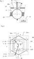
- the figure 1 represents a control lever 10 of a game controller.
- a control lever 10 may also be called “joystick” or “stick”.
- a control lever 10 is disposed on an upper surface of a game controller, to be actuated and moved by a user of a video game console, to cause for example a movement of a character, a moving a sighting target, or a movement of a virtual camera of a video game.
- control lever 10 is therefore movable relative to a housing 20 of the video game controller, and can be articulated with respect to the housing 20 in a ball joint connection as shown figure 1 .
- Other connections between the control lever 10 and the housing 20 are possible, such as for example a connection which allows only a plane movement of the control lever 10.
- control lever 10 can be moved only in a predefined displacement zone, and limited by a stop 20a.
- the stop 20a is an edge of the housing 20, forming a hole through which the control lever 10 passes through the housing 20.
- the latter is connected to at least a position sensor 12, such as a potentiometer.
- a position sensor 12 makes it possible to detect the movements of the control lever 10, and thus to calculate, for example, a position of a point PL of the control lever 10.
- control lever 10 can be moved here in two degrees of freedom, so that one can of course provide two position sensors, or a single position sensor with two measuring tracks to measure accurately all positions that the control lever 10 can occupy.
- the abutment 20a is for example a polygon (such as a pentagon, hexagon, heptagon, octagon, dodecagon, ellipse), and if the positions of the point PL are projected in a base plane, perpendicular or substantially perpendicular to the control lever when the latter is in the rest position (as shown figure 1 in solid lines), the projected positions are all contained in a visible Hb abutment hexagon figures 2 or 3 , and whose peaks are A, B, C, D, E and F.
- the base plane may be inclined to a few degrees of a plane perpendicular to the control lever when the latter is in the rest position, and the projections will be all contained in a non-regular hexagon in the case where the mechanical stop is a hexagon.
- control lever 10 is limited by a hexagon, but the game console must receive a position of the control lever 10 in the form of a set of Cartesian coordinates, and the norm of a vector between the origin of the Cartesian coordinate system and the projected position in the base plane must be maximal.
- the invention proposes to calculate the set of coordinates that will be sent to the game console by making a homothmatie from the projected position of the control lever 10 in the basic plane.
- the figure 2 represents a first implementation of this calculation, in two cases.
- the control lever is in position X1, and the projected position in the base plane has coordinates (a1, a2).
- a homothetic figure FH of the abutment hexagon Hb which passes through the projected position of coordinates (a1, a2), and which is centered on the rest position of the control lever (the origin of the reference (xx ', yy')). This is the hexagon abcdef.
- the method first determines the angle ⁇ between an axis of the mark xx 'and the radius passing through the projected position, to determine in which angular sector of the plane is the projected position. Indeed, this angular determination is necessary to determine which equation of the right must be solved to find an edge parallel to the abutment hexagon Hb.
- the angle ⁇ makes it possible to determine that the projected position is on a straight line parallel to the edge FA of the abutment hexagon Hb. It is then possible to determine with certainty the line parallel to (FA) and then the homothetic figure FH which passes through the projected position of coordinates (a1, a2), which is the hexagon of vertices abcdef.
- the process determines a circumscribed square Ccfh to the homothetic figure FH (it is the square which has the double side of the length Oa, that is to say the ordinate a'2), and determines the intersection point of the radius passing through the projected position of coordinates (a1, a2) with the circumscribed square Ccfh, whose coordinates are (a'1, a'2).
- the method thus performs a homothety based on a difference in size between the homothetic figure FH and its circumscribed square Ccfh.
- One artificially “increases” or “moves” the projected position to the circumscribed square Ccfh, to find the second set of coordinates. This is a projection in the radial direction.
- the second set of coordinates is equal to the first set of coordinates when the control lever is moved only on a vertical cardinal direction (along the axis yy '): the homothety is then of ratio 1. Moreover, the ratio of homothety is maximum when the control lever 10 is moved along a diagonal at 45 °.
- the console receives a second set of Cartesian coordinates, with full scale only when the control lever is in abutment, and without ignoring a measurement zone.
- the X2 position of the figure 2 is precisely the control lever 10 abutting, and the coordinates of the projected position are (b1, b2), located on the abutment hexagon Hb.
- the transformation amounts to calculating the projection of the projected position on the circumscribed square Ccm according to the radial direction passing through the projected position, to calculate the second set of coordinates (b'1, b'2) which will be sent to the console.
- the method according to the invention can perform the steps of determining the homothetic figure, the circumscribed square Ccfh and projection at each measurement of the position of the control lever 10 to calculate the second set of coordinates with the homothetic ratio, or Well we can build a predefined table by calculating the homothetic ratio for all possible positions, store this predefined table in the game controller and simply find the appropriate ratio according to a measured position, and multiply the coordinates measured by the adequate report to find the second set of coordinates. Alternatively, the second set of coordinates can be stored directly in the predefined table.
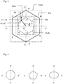
- the figure 3 represents a first alternative.
- the determination of the homothetic figure FH and the circumscribed square Ccfh are identical.
- the method instead of projecting the projected position in the radial direction, the method performs a single projection parallel to one of the axes xx 'or yy', and in particular to the side of the circumscribed square which is nearest, to find the second set of Cartesian coordinates to send to the game console.
- the figure 4 represents variants of the shape of the mechanical stop defining the zone of movement of the control lever, with from left to right an octagon, a pentagon, or an ellipse.
- the method will use, before determining the equation of the homothetic figure passing through the projected position, a determination of the angular sector where the projected position is, to identify with which side of the mechanical stop it is necessary to determine the parallel line passing through the projected position and defining the homothetic figure.
- a determination of the angular sector where the projected position is to identify with which side of the mechanical stop it is necessary to determine the parallel line passing through the projected position and defining the homothetic figure.
- the method can, after the projection of the position of the lever in the base plane, directly determine the equation of a homothetic ellipse to the stop, and that goes through the projected position.
- the invention includes a step of providing a polygonal or elliptical shaped abutment.
- the invention relates to the conversion of coordinates of a manipulated lever within the limits of a mechanical stop, so there is a step which consists in manufacturing and providing such a mechanical abutment of polygonal or elliptical shape on a controller of games.
Landscapes
- Engineering & Computer Science (AREA)
- Multimedia (AREA)
- Human Computer Interaction (AREA)
- Physics & Mathematics (AREA)
- General Engineering & Computer Science (AREA)
- General Physics & Mathematics (AREA)
- Theoretical Computer Science (AREA)
- Optics & Photonics (AREA)
- Automation & Control Theory (AREA)
- Position Input By Displaying (AREA)
Priority Applications (9)
| Application Number | Priority Date | Filing Date | Title |
|---|---|---|---|
| EP17306074.0A EP3444016A1 (de) | 2017-08-17 | 2017-08-17 | Verfahren zur kontrolle eines anzeigeelements mithilfe einer spielkonsole |
| ES18750222T ES2894130T3 (es) | 2017-08-17 | 2018-08-10 | Procedimiento de control de un elemento de visualización por una consola de juegos |
| EP18750222.4A EP3668621B1 (de) | 2017-08-17 | 2018-08-10 | Verfahren zur kontrolle eines anzeigeelements mithilfe einer spielkonsole |
| PCT/EP2018/071781 WO2019034560A1 (fr) | 2017-08-17 | 2018-08-10 | Procede de controle d'un element d'affichage par une console de jeux |
| CN201880053243.8A CN111225723B (zh) | 2017-08-17 | 2018-08-10 | 通过游戏控制台控制显示元件的方法 |
| US16/639,684 US11077372B2 (en) | 2017-08-17 | 2018-08-10 | Method for controlling a display element by a games console |
| CA3073126A CA3073126A1 (fr) | 2017-08-17 | 2018-08-10 | Procede de controle d'un element d'affichage par une console de jeux |
| RU2020107013A RU2767456C2 (ru) | 2017-08-17 | 2018-08-10 | Способ управления элементом отображения посредством консоли для игр |
| JP2020530723A JP7282773B2 (ja) | 2017-08-17 | 2018-08-10 | ゲームコンソールによる表示要素の制御方法 |
Applications Claiming Priority (1)
| Application Number | Priority Date | Filing Date | Title |
|---|---|---|---|
| EP17306074.0A EP3444016A1 (de) | 2017-08-17 | 2017-08-17 | Verfahren zur kontrolle eines anzeigeelements mithilfe einer spielkonsole |
Publications (1)
| Publication Number | Publication Date |
|---|---|
| EP3444016A1 true EP3444016A1 (de) | 2019-02-20 |
Family
ID=59761896
Family Applications (2)
| Application Number | Title | Priority Date | Filing Date |
|---|---|---|---|
| EP17306074.0A Withdrawn EP3444016A1 (de) | 2017-08-17 | 2017-08-17 | Verfahren zur kontrolle eines anzeigeelements mithilfe einer spielkonsole |
| EP18750222.4A Active EP3668621B1 (de) | 2017-08-17 | 2018-08-10 | Verfahren zur kontrolle eines anzeigeelements mithilfe einer spielkonsole |
Family Applications After (1)
| Application Number | Title | Priority Date | Filing Date |
|---|---|---|---|
| EP18750222.4A Active EP3668621B1 (de) | 2017-08-17 | 2018-08-10 | Verfahren zur kontrolle eines anzeigeelements mithilfe einer spielkonsole |
Country Status (8)
| Country | Link |
|---|---|
| US (1) | US11077372B2 (de) |
| EP (2) | EP3444016A1 (de) |
| JP (1) | JP7282773B2 (de) |
| CN (1) | CN111225723B (de) |
| CA (1) | CA3073126A1 (de) |
| ES (1) | ES2894130T3 (de) |
| RU (1) | RU2767456C2 (de) |
| WO (1) | WO2019034560A1 (de) |
Families Citing this family (2)
| Publication number | Priority date | Publication date | Assignee | Title |
|---|---|---|---|---|
| EP3285148A1 (de) | 2016-08-19 | 2018-02-21 | Bigben Interactive SA | Verfahren zur kontrolle eines anzeigeelements über eine spielkonsole |
| CN116370070B (zh) * | 2023-01-10 | 2025-10-28 | 上海微创微航机器人有限公司 | 导管运动控制方法、装置、系统和存储介质 |
Citations (7)
| Publication number | Priority date | Publication date | Assignee | Title |
|---|---|---|---|---|
| EP2450776A1 (de) | 2010-10-20 | 2012-05-09 | Nxp B.V. | Benutzerschnittstelle zur Steuerung eines Datenverarbeitungssystems mit einem Joystick |
| EP2524721A2 (de) * | 2011-05-19 | 2012-11-21 | Nintendo Co., Ltd. | Informationsverarbeitungsprogramm, Informationsverarbeitungsvorrichtung, Informationsverarbeitungssystem und Informationsverarbeitungsverfahren |
| US20130100021A1 (en) * | 2011-10-20 | 2013-04-25 | Sony Computer Entertainment Inc. | Multi-sensored control stick for enhanced input sensitivity and functionality |
| JP2013176457A (ja) * | 2012-02-28 | 2013-09-09 | Hori Co Ltd | ゲーム機用ジョイスティック装置 |
| WO2014106594A1 (fr) * | 2013-01-04 | 2014-07-10 | Movea | Element mobile de commande prehensible simulant un joystick ou manette de jeu equivalente a au moins un element de commande a butee physique, et procede de simulation associe |
| US20140298942A1 (en) * | 2011-08-08 | 2014-10-09 | Yamaha Corporation | Manipulator device |
| FR3031404A1 (fr) * | 2015-01-03 | 2016-07-08 | Bigben Interactive Sa | Procede de controle d'un curseur de visee |
Family Cites Families (20)
| Publication number | Priority date | Publication date | Assignee | Title |
|---|---|---|---|---|
| MX9700277A (es) * | 1995-05-10 | 1997-05-31 | Nintendo Co Ltd | Sistema de procesamiento de imagenes que utiliza palanca de mando analogica. |
| KR100371456B1 (ko) * | 1995-10-09 | 2004-03-30 | 닌텐도가부시키가이샤 | 삼차원화상처리시스템 |
| KR100320262B1 (ko) * | 1996-08-05 | 2002-04-22 | 기노시타 구니아키 | 디스플레이화상에서의지점을지정하는장치와방법및디스플레이되는화상에서의지점을지정하기위한프로그램을저장하는읽을수있는기록매체 |
| US6396473B1 (en) * | 1999-04-22 | 2002-05-28 | Webtv Networks, Inc. | Overlay graphics memory management method and apparatus |
| JP3474156B2 (ja) * | 1999-09-10 | 2003-12-08 | 株式会社ソニー・コンピュータエンタテインメント | エンタテインメント装置、記憶媒体およびパラメータ設定方法 |
| US7854655B2 (en) * | 2002-07-27 | 2010-12-21 | Sony Computer Entertainment America Inc. | Obtaining input for controlling execution of a game program |
| JP4167477B2 (ja) * | 2002-11-25 | 2008-10-15 | 日本電気株式会社 | ポインティングデバイス及び電子機器 |
| US20050009605A1 (en) * | 2003-07-11 | 2005-01-13 | Rosenberg Steven T. | Image-based control of video games |
| FR2908323B1 (fr) * | 2006-11-09 | 2009-01-16 | Parrot Sa | Procede de definition d'un referentiel commun pour un systeme de jeux video |
| FR2908324B1 (fr) * | 2006-11-09 | 2009-01-16 | Parrot Sa | Procede d'ajustement d'affichage pour un systeme de jeux video |
| JP4384697B2 (ja) * | 2008-03-26 | 2009-12-16 | 株式会社コナミデジタルエンタテインメント | ゲーム装置、ゲーム処理方法、ならびに、プログラム |
| US8142288B2 (en) * | 2009-05-08 | 2012-03-27 | Sony Computer Entertainment America Llc | Base station movement detection and compensation |
| FR2948471B1 (fr) * | 2009-07-21 | 2016-02-26 | Commissariat Energie Atomique | Procede et dispositif de localisation d'au moins un toucher sur une surface tactile d'un objet |
| US9110557B2 (en) * | 2010-05-04 | 2015-08-18 | Timocco Ltd. | System and method for tracking and mapping an object to a target |
| US9033805B2 (en) * | 2012-01-19 | 2015-05-19 | Zynga Inc. | Three dimensional operations in an isometric projection |
| CN202735972U (zh) * | 2012-08-31 | 2013-02-13 | 华南理工大学 | 一种光电式摇杆 |
| US10521520B2 (en) * | 2013-02-14 | 2019-12-31 | Nocturnal Innovations LLC | Highly scalable cluster engine for hosting simulations of objects interacting within a space |
| AU2013202150A1 (en) | 2013-03-28 | 2014-10-16 | Aristocrat Technologies Australia Pty Limited | An electronic method of gaming, a game controller and a gaming system |
| RU2611989C2 (ru) * | 2015-08-21 | 2017-03-01 | Алексей Евгеньевич Несмеев | Игровой контроллер |
| CN106621318B (zh) * | 2016-12-30 | 2019-11-29 | 大连大学 | 一种基于传感器mpu6050采集信号的手柄摇杆系统和方法 |
-
2017
- 2017-08-17 EP EP17306074.0A patent/EP3444016A1/de not_active Withdrawn
-
2018
- 2018-08-10 CN CN201880053243.8A patent/CN111225723B/zh active Active
- 2018-08-10 RU RU2020107013A patent/RU2767456C2/ru active
- 2018-08-10 WO PCT/EP2018/071781 patent/WO2019034560A1/fr not_active Ceased
- 2018-08-10 US US16/639,684 patent/US11077372B2/en active Active
- 2018-08-10 EP EP18750222.4A patent/EP3668621B1/de active Active
- 2018-08-10 ES ES18750222T patent/ES2894130T3/es active Active
- 2018-08-10 JP JP2020530723A patent/JP7282773B2/ja active Active
- 2018-08-10 CA CA3073126A patent/CA3073126A1/fr active Pending
Patent Citations (7)
| Publication number | Priority date | Publication date | Assignee | Title |
|---|---|---|---|---|
| EP2450776A1 (de) | 2010-10-20 | 2012-05-09 | Nxp B.V. | Benutzerschnittstelle zur Steuerung eines Datenverarbeitungssystems mit einem Joystick |
| EP2524721A2 (de) * | 2011-05-19 | 2012-11-21 | Nintendo Co., Ltd. | Informationsverarbeitungsprogramm, Informationsverarbeitungsvorrichtung, Informationsverarbeitungssystem und Informationsverarbeitungsverfahren |
| US20140298942A1 (en) * | 2011-08-08 | 2014-10-09 | Yamaha Corporation | Manipulator device |
| US20130100021A1 (en) * | 2011-10-20 | 2013-04-25 | Sony Computer Entertainment Inc. | Multi-sensored control stick for enhanced input sensitivity and functionality |
| JP2013176457A (ja) * | 2012-02-28 | 2013-09-09 | Hori Co Ltd | ゲーム機用ジョイスティック装置 |
| WO2014106594A1 (fr) * | 2013-01-04 | 2014-07-10 | Movea | Element mobile de commande prehensible simulant un joystick ou manette de jeu equivalente a au moins un element de commande a butee physique, et procede de simulation associe |
| FR3031404A1 (fr) * | 2015-01-03 | 2016-07-08 | Bigben Interactive Sa | Procede de controle d'un curseur de visee |
Also Published As
| Publication number | Publication date |
|---|---|
| EP3668621B1 (de) | 2021-09-08 |
| CN111225723B (zh) | 2023-07-14 |
| EP3668621A1 (de) | 2020-06-24 |
| JP7282773B2 (ja) | 2023-05-29 |
| ES2894130T3 (es) | 2022-02-11 |
| RU2767456C2 (ru) | 2022-03-17 |
| US20200261800A1 (en) | 2020-08-20 |
| CA3073126A1 (fr) | 2019-02-21 |
| RU2020107013A3 (de) | 2022-01-21 |
| US11077372B2 (en) | 2021-08-03 |
| WO2019034560A1 (fr) | 2019-02-21 |
| JP2020531214A (ja) | 2020-11-05 |
| RU2020107013A (ru) | 2021-08-16 |
| CN111225723A (zh) | 2020-06-02 |
Similar Documents
| Publication | Publication Date | Title |
|---|---|---|
| EP1733181B1 (de) | Gemischer optischer und mechanischer sensor und dazugehöriges rücksetzverfahren | |
| FR2957266A1 (fr) | Procede et appareil de telecommande d'un drone, notamment d'un drone a voilure tournante. | |
| EP3500914B1 (de) | Verfahren zur kontrolle eines anzeigeelements über eine spielkonsole | |
| EP3668621B1 (de) | Verfahren zur kontrolle eines anzeigeelements mithilfe einer spielkonsole | |
| FR2958033A1 (fr) | Dispositif d'affichage de la variation d'energie d'un aeronef, procede et systeme d'affichage de la variation d'energie correspondants | |
| EP3626530B1 (de) | Manövriersystem einer fördervorrichtung, die für die ausstattung eines fahrgestells eines fahrzeugs zur beladung und entladung einer kiste bestimmt ist | |
| FR2958050A1 (fr) | Procede et systeme de gestion de la variation d'energie d'un aeronef | |
| FR2903658A1 (fr) | Systeme de commandes de vol et de commande de direction au sol pour aeronef. | |
| EP3519143B1 (de) | Anlage mit einem gelenkarm und einer bearbeitungsmaschine und entsprechendes bearbeitungsverfahren | |
| EP0642075A1 (de) | Verfahren und Vorrichtung zur Verwaltung von relativen Kursorverschiebungen hinsichtlich des auf der Bildanzeigevorrichtung dargestellten Bildes | |
| EP3060929B1 (de) | Verfahren und vorrichtung zur messung des winkels eines angriffs und des schiebewinkels eines flugzeugs | |
| FR3051856A1 (fr) | Cylindre hydraulique emetteur pour un dispositif de commande hydraulique | |
| EP3281870A1 (de) | Videoerfassungsverfahren für eine drohne, entsprechendes computerprogramm und entsprechendes elektronisches system zur erfassung eines videos | |
| WO2015090553A1 (fr) | Procede et systeme de calibration d'une camera d'un vehicule | |
| FR3116806A1 (fr) | Drone volant pour l’inspection de surfaces et procédé d’inspection de surfaces au moyen d’un tel drone volant | |
| CA3033332C (fr) | Procede de controle d'un element d'affichage par une console de jeux | |
| EP3579191A1 (de) | Dynamische schätzung des momentanen nick- und rollwinkels einer in einem kraftfahrzeug eingebauten videokamera | |
| EP1361421A1 (de) | Verfahren zur Berechnung der Kräfte zwischen einem drehenden Element und einem Träger | |
| EP3081484B1 (de) | Steuersystem eines rotors eines drehflügelflugzeugs, mit einem solchen system ausgestattetes drehflügelflugzeug und entsprechende steuermethode | |
| FR3025025A1 (fr) | Procede de determination de la posture relative d'un engin mobile par rapport a un ouvrage d'art et engin mobile adapte | |
| FR2903660A1 (fr) | Systeme de commandes de vol electriques pour aeronef et siege l'incorporant | |
| FR2962973A1 (fr) | Systeme de commandes de vol electriques pour aeronef. | |
| FR2978942A1 (fr) | Procede et dispositif d'affichage pour vehicule, element de vehicule muni d'un tel dispositif et vehicule muni d'un tel element. | |
| FR3135810A1 (fr) | Procédé de génération d’une image périphérique d’un aéronef, dispositif électronique de génération et produit programme d’ordinateur associés | |
| CA3047766A1 (fr) | Systeme d'aide au pilotage d'un aeronef, aeronef associe et procede d'aide au pilotage de cet aeronef |
Legal Events
| Date | Code | Title | Description |
|---|---|---|---|
| PUAI | Public reference made under article 153(3) epc to a published international application that has entered the european phase |
Free format text: ORIGINAL CODE: 0009012 |
|
| AK | Designated contracting states |
Kind code of ref document: A1 Designated state(s): AL AT BE BG CH CY CZ DE DK EE ES FI FR GB GR HR HU IE IS IT LI LT LU LV MC MK MT NL NO PL PT RO RS SE SI SK SM TR |
|
| AX | Request for extension of the european patent |
Extension state: BA ME |
|
| STAA | Information on the status of an ep patent application or granted ep patent |
Free format text: STATUS: THE APPLICATION IS DEEMED TO BE WITHDRAWN |
|
| 18D | Application deemed to be withdrawn |
Effective date: 20190821 |