EP3444066B1 - Dispositif de réception d'une pièce à usiner en forme d'anneau ou de disque sur une machine-outil - Google Patents
Dispositif de réception d'une pièce à usiner en forme d'anneau ou de disque sur une machine-outil Download PDFInfo
- Publication number
- EP3444066B1 EP3444066B1 EP18187626.9A EP18187626A EP3444066B1 EP 3444066 B1 EP3444066 B1 EP 3444066B1 EP 18187626 A EP18187626 A EP 18187626A EP 3444066 B1 EP3444066 B1 EP 3444066B1
- Authority
- EP
- European Patent Office
- Prior art keywords
- receiving part
- workpiece
- upper receiving
- actuating elements
- elements
- Prior art date
- Legal status (The legal status is an assumption and is not a legal conclusion. Google has not performed a legal analysis and makes no representation as to the accuracy of the status listed.)
- Active
Links
Images



Classifications
-
- B—PERFORMING OPERATIONS; TRANSPORTING
- B23—MACHINE TOOLS; METAL-WORKING NOT OTHERWISE PROVIDED FOR
- B23Q—DETAILS, COMPONENTS, OR ACCESSORIES FOR MACHINE TOOLS, e.g. ARRANGEMENTS FOR COPYING OR CONTROLLING; MACHINE TOOLS IN GENERAL CHARACTERISED BY THE CONSTRUCTION OF PARTICULAR DETAILS OR COMPONENTS; COMBINATIONS OR ASSOCIATIONS OF METAL-WORKING MACHINES, NOT DIRECTED TO A PARTICULAR RESULT
- B23Q1/00—Members which are comprised in the general build-up of a form of machine, particularly relatively large fixed members
- B23Q1/0009—Energy-transferring means or control lines for movable machine parts; Control panels or boxes; Control parts
- B23Q1/0018—Energy-transferring means or control lines for movable machine parts; Control panels or boxes; Control parts comprising hydraulic means
-
- B—PERFORMING OPERATIONS; TRANSPORTING
- B23—MACHINE TOOLS; METAL-WORKING NOT OTHERWISE PROVIDED FOR
- B23Q—DETAILS, COMPONENTS, OR ACCESSORIES FOR MACHINE TOOLS, e.g. ARRANGEMENTS FOR COPYING OR CONTROLLING; MACHINE TOOLS IN GENERAL CHARACTERISED BY THE CONSTRUCTION OF PARTICULAR DETAILS OR COMPONENTS; COMBINATIONS OR ASSOCIATIONS OF METAL-WORKING MACHINES, NOT DIRECTED TO A PARTICULAR RESULT
- B23Q3/00—Devices holding, supporting, or positioning work or tools, of a kind normally removable from the machine
- B23Q3/12—Devices holding, supporting, or positioning work or tools, of a kind normally removable from the machine for securing to a spindle in general
-
- B—PERFORMING OPERATIONS; TRANSPORTING
- B23—MACHINE TOOLS; METAL-WORKING NOT OTHERWISE PROVIDED FOR
- B23B—TURNING; BORING
- B23B31/00—Chucks; Expansion mandrels; Adaptations thereof for remote control
- B23B31/02—Chucks
- B23B31/10—Chucks characterised by the retaining or gripping devices or their immediate operating means
- B23B31/12—Chucks with simultaneously-acting jaws, whether or not also individually adjustable
- B23B31/16—Chucks with simultaneously-acting jaws, whether or not also individually adjustable moving radially
-
- B—PERFORMING OPERATIONS; TRANSPORTING
- B23—MACHINE TOOLS; METAL-WORKING NOT OTHERWISE PROVIDED FOR
- B23B—TURNING; BORING
- B23B31/00—Chucks; Expansion mandrels; Adaptations thereof for remote control
- B23B31/02—Chucks
- B23B31/24—Chucks characterised by features relating primarily to remote control of the gripping means
- B23B31/30—Chucks characterised by features relating primarily to remote control of the gripping means using fluid-pressure means in the chuck
-
- B—PERFORMING OPERATIONS; TRANSPORTING
- B23—MACHINE TOOLS; METAL-WORKING NOT OTHERWISE PROVIDED FOR
- B23B—TURNING; BORING
- B23B31/00—Chucks; Expansion mandrels; Adaptations thereof for remote control
- B23B31/02—Chucks
- B23B31/24—Chucks characterised by features relating primarily to remote control of the gripping means
- B23B31/30—Chucks characterised by features relating primarily to remote control of the gripping means using fluid-pressure means in the chuck
- B23B31/302—Hydraulic equipment, e.g. pistons, valves, rotary joints
-
- B—PERFORMING OPERATIONS; TRANSPORTING
- B23—MACHINE TOOLS; METAL-WORKING NOT OTHERWISE PROVIDED FOR
- B23Q—DETAILS, COMPONENTS, OR ACCESSORIES FOR MACHINE TOOLS, e.g. ARRANGEMENTS FOR COPYING OR CONTROLLING; MACHINE TOOLS IN GENERAL CHARACTERISED BY THE CONSTRUCTION OF PARTICULAR DETAILS OR COMPONENTS; COMBINATIONS OR ASSOCIATIONS OF METAL-WORKING MACHINES, NOT DIRECTED TO A PARTICULAR RESULT
- B23Q1/00—Members which are comprised in the general build-up of a form of machine, particularly relatively large fixed members
- B23Q1/25—Movable or adjustable work or tool supports
-
- B—PERFORMING OPERATIONS; TRANSPORTING
- B23—MACHINE TOOLS; METAL-WORKING NOT OTHERWISE PROVIDED FOR
- B23Q—DETAILS, COMPONENTS, OR ACCESSORIES FOR MACHINE TOOLS, e.g. ARRANGEMENTS FOR COPYING OR CONTROLLING; MACHINE TOOLS IN GENERAL CHARACTERISED BY THE CONSTRUCTION OF PARTICULAR DETAILS OR COMPONENTS; COMBINATIONS OR ASSOCIATIONS OF METAL-WORKING MACHINES, NOT DIRECTED TO A PARTICULAR RESULT
- B23Q17/00—Arrangements for observing, indicating or measuring on machine tools
- B23Q17/002—Arrangements for observing, indicating or measuring on machine tools for indicating or measuring the holding action of work or tool holders
- B23Q17/005—Arrangements for observing, indicating or measuring on machine tools for indicating or measuring the holding action of work or tool holders by measuring a force, a pressure or a deformation
-
- B—PERFORMING OPERATIONS; TRANSPORTING
- B23—MACHINE TOOLS; METAL-WORKING NOT OTHERWISE PROVIDED FOR
- B23Q—DETAILS, COMPONENTS, OR ACCESSORIES FOR MACHINE TOOLS, e.g. ARRANGEMENTS FOR COPYING OR CONTROLLING; MACHINE TOOLS IN GENERAL CHARACTERISED BY THE CONSTRUCTION OF PARTICULAR DETAILS OR COMPONENTS; COMBINATIONS OR ASSOCIATIONS OF METAL-WORKING MACHINES, NOT DIRECTED TO A PARTICULAR RESULT
- B23Q3/00—Devices holding, supporting, or positioning work or tools, of a kind normally removable from the machine
- B23Q3/02—Devices holding, supporting, or positioning work or tools, of a kind normally removable from the machine for mounting on a work-table, tool-slide, or analogous part
- B23Q3/06—Work-clamping means
- B23Q3/08—Work-clamping means other than mechanically-actuated
- B23Q3/082—Work-clamping means other than mechanically-actuated hydraulically actuated
Definitions
- the invention relates to a device for receiving an annular or disk-shaped workpiece on a machine tool.
- Workpieces of the type mentioned are required, for example, in cycloid gears; these are in particular so-called pin rings (also called “needle rings”). Workpieces of this type have a profiling which, depending on the intended use, may need to be precisely hard-machined. In addition, there are also cylindrical surfaces as well as flat surfaces that must be machined with equal precision. The required tolerances are often in a range that makes reclamping the workpiece difficult for machining on different machine tools.
- a device of this type is in the US 6 123 341 A1 described.
- a similar solution shows the US 7 654 178 B2 .
- the DE 1 048 108 A a pressure transmission device that works with flexible membranes.
- a similar solution shows the DE 645 770 A for a detachable connection for the connection lines of pressure gauges.
- the invention is based on the object of designing a device of the type mentioned at the outset in such a way that it is possible to clamp ring-shaped or disk-shaped workpieces with high precision and then to machine them on a plurality of processing surfaces in one setting. Particularly precise machining of the workpiece on several surfaces should therefore be possible. Furthermore, it should also be possible to process different workpieces with high precision and economically.
- the proposed special clamping element for receiving ring-shaped or disk-shaped workpieces thus consists of a lower part which is connected to the machine tool and here in particular to a rotary table thereof, and an upper part which carries the workpiece.
- actuating elements are provided, which preferably operate by hydraulics (optionally also pneumatically), a movement caused by the (hydraulic) fluid being transmitted from the lower part to the upper part via the transmission elements mentioned.
- a major advantage of this configuration is that several receiving upper parts with different dimensions and in particular with different diameters can be manufactured and then combined with the lower part, which is achieved by the detachable fastening between the upper part and the lower part.
- the transmission elements are preferably designed as elastic membranes.
- the membranes are preferably made of an elastomeric material or metal. A very ductile metallic material can advantageously be used for the membrane.
- the transmission elements are designed as pistons, which are arranged displaceably in the receiving space.
- the pistons are preferably made of ceramic material.
- At least 3 and preferably up to 12 actuating elements are arranged in the upper receiving part around the central axis, particularly preferably 9 actuating elements.
- the actuating elements are preferably arranged equidistantly around the central axis.
- a preferred development provides that a number of detachable electrical contacts corresponding to the number of actuating elements is arranged, part of the electrical contact being arranged in the upper part of the receptacle and part of the electrical contact in the lower part of the receptacle.
- a pressure sensor can be arranged in each actuating element, an electrical signal of the pressure sensor corresponding to the pressure being able to be transmitted via the electrical contact from the upper receiving part to the lower receiving part.
- Centering means are preferably arranged with which the upper receiving part can be centered relative to the lower receiving part.
- the centering means can be designed as conically interacting sections.
- An electronic controller arranged in the lower part of the receptacle is preferably assigned to each actuator. This is responsible in particular for the controlled generation of force or displacement movement in the actuating element.
- the receiving upper part preferably has a supporting surface for the workpiece, at least one electrical magnet being arranged in the region of the supporting surface, with which the workpiece can be fixed on or on the upper receiving part.
- an electric magnet is assigned to each actuating element.
- the device is preferably arranged on a rotary table of the machine tool in order to be able to rotate about the central axis. This makes it possible, for example, to carry out a turning operation on a bore or flat surface.
- the actuating elements are preferably detachably fastened in the upper receiving part. This makes it possible to replace them in a modular manner, making it easy to adapt them to different workpieces.
- the actuators can also be designed in the form of elastic membranes or (ceramic) pistons or have such elements, ie the technology described above for the transfer element can also be used for the actuators.
- the actuating elements are at a defined axial height (based on the axial extent of the workpiece) around the circumference of the workpiece.
- the workpiece has a particularly large axial extent, that is to say if the workpieces are, for example, tubular (with a relatively large axial extent in relation to the diameter)
- two (or more) groups Actuating elements that are axially offset are arranged in order to simultaneously contact or clamp the workpiece at different axial positions by means of the actuating elements (in the exemplary embodiment explained below, 2 x 9 actuating elements would then be provided, the second nine actuating elements being the first nine actuators (in the direction of the central axis) would be axially offset).
- a grinding process is usually used to process the profile.
- the cylindrical bore surfaces and flat surfaces can be machined by turning (fine turning) and, if necessary, subsequent cylindrical or face grinding.
- the proposed device is used particularly advantageously for the pin rings of cycloid gears.
- the device allows workpieces of the type mentioned to be machined with very high precision with good productivity.
- Fig. 1 the bolt ring 2 of a cycloid gear is shown, which is to be clamped with the device described below and then to be finished on a machine tool.
- the bolt ring 2 has a central axis a, which corresponds to the axis of the device described below.
- the radial direction r extends.
- the aim is to machine the profiling 21, the two cylindrical bore surfaces 22 and 23 and the end face 24 in one setting, so that reclamping of the workpiece with the associated accuracy problems becomes unnecessary.
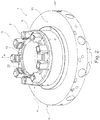
- FIGS Figures 2 to 6 For this purpose, a device 1 is used, as shown in FIGS Figures 2 to 6 is shown completely or in parts.
- the device 1 for receiving and clamping the workpiece 2 is received on the machine table (rotary table) of a machine tool 3, as it turns out Figure 3 results.
- the device 1 has an upper receiving part 4 and a lower receiving part 5, which together form the device 1.
- the lower part 5 is connected to the machine table of the machine tool 3, while the upper part 4 is detachably connected to the lower part 5 coaxially to the central axis a.
- Centering means 17 (with interacting cone sections) ensure centering in the radial direction r between the upper receiving part 4 and the lower receiving part 5.
- the detachability of the upper holding part 4 and lower holding part 5 enables the lower holding part 5 to remain mounted in the machine tool 3 and, by exchanging the upper holding part 4, a receptacle suitable for a special workpiece 2 is mounted on the lower holding part 5. This significantly increases the economy of machining.
- Actuating elements 6 serve to center the workpiece 2 with respect to the central axis a and to clamp it, a number of which - in the exemplary embodiment nine - are arranged around the central axis a.
- Each actuating element 6 works as a self-sufficient hydraulic element, which can exert a bearing force on the workpiece 2 or a radial displacement path in the radial direction r.
- the actuating elements 6 are acted upon hydraulically, which is done by means of actuators 7, which are arranged in the lower receiving part 5.
- a translatory displacement of the actuator 7 leads to a displacement of hydraulic oil, which ultimately leads to an actuating movement in the actuating element 6.
- Transfer elements 8 are used for this purpose, as detailed in FIG Figure 4 you can see.
- An upper section 9 of the transfer element 8 is located in the upper receiving part 4, while a lower section 10 of the transfer element 8 is located in the lower receiving part 5.
- Each section 9, 10 has a receiving space 11 or 12 for hydraulic fluid. Furthermore, the receiving space 11 or 12 is delimited by a transmission element 13 or 14, respectively.
- the two transmission elements 13 and 14 lie against each other and in the trend plane 15 between the upper receiving part 4 and the lower receiving part 5 (see FIG. Figure 4 ).
- a hermetic seal particularly with regard to the lower part of the receptacle, should not be understood to mean that a refill tank for pressurized fluid may not be present here. With such a leakage of the actuator (ie the adjusting piston) can be compensated for if necessary.
- each actuating element 6 there is a pressure sensor (not shown), the electrical signal of which must be transmitted from the upper receiving part 4 to the lower receiving part 5. Electrical contacts 16 serve this purpose, the number of which in turn corresponds to that of the actuating elements 6.
- Electrical magnets 20, which are arranged in the region of the support surface 19 for the workpiece 2 and are thus able to fix the workpiece 2 relative to the upper holding part 4, serve to fix the workpiece 2 in or on the upper holding part 4.
- Each of the (in the exemplary embodiment: nine) actuators 7 thus has its own controller 18 in the chuck, which enables individual positioning of an individual actuator 7 by the PLC (programmable logic controller) of the machine tool.
- PLC programmable logic controller
- the PLC is connected to the controllers 18 by means of a bus system.
- the pressure in the actuating elements 6 is determined by the pressure sensor already mentioned and not shown, which is detected directly by the associated controller 18.
- An electrical magnet 20 is assigned to each individual actuating element 6 (clamping element). The control takes place via a digital output of the actuator controller.
- the actuating elements 6 (clamping elements) are applied to the workpiece 2 in a pressure-controlled, autonomous manner by the PLC in conjunction with the actuator controllers.
- the NC control of the machine tool detects the position of the workpiece 2 and calculates the displacement paths of the individual actuating elements 6 (clamping elements). These values are passed on to the PLC, which determines a travel path for the individual actuators 7 and controls them accordingly. At least one measuring probe, which is stationary in the machine tool and which verifies the end position of the workpiece 2 to be reached, serves as an additional control variable.
- the proposed device 1 allows the profiling 21, the cylindrical bore surfaces 22 and 23 and the end face 24 to be machined in one setting, so that a high degree of precision can be achieved.
Landscapes
- Engineering & Computer Science (AREA)
- Mechanical Engineering (AREA)
- Gripping On Spindles (AREA)
- Jigs For Machine Tools (AREA)
Claims (12)
- Dispositif (1) de réception d'une pièce à usiner (2) en forme d'anneau ou de disque sur une machine-outil (3), comprenant :une partie supérieure de réception (4), qui est destinée à recevoir la pièce à usiner (2), et une partie inférieure de réception (5), qui est destinée à être reçue dans la machine-outil (3), dans lequel la partie supérieure de réception (4) et la partie inférieure de réception (5) peuvent être reliées l'une à l'autre de manière amovible, coaxialement par rapport à un axe central (a),dans lequel la partie supérieure de réception (4) comporte un certain nombre d'éléments d'actionnement (6) disposés autour de l'axe central (a), avec lesquels une force agissant radialement (r) et/ou un déplacement radial peuvent être respectivement exercés sur la pièce à usiner (2), dans lequel les éléments d'actionnement (6) sont actionnés par le refoulement d'un fluide sous pression, en particulier d'une huile hydraulique,dans lequel il est prévu dans la partie inférieure de réception (5) un nombre d'actionneurs (7) correspondant au nombre d'éléments d'actionnement (6), au moyen desquels un volume défini de fluide sous pression peut respectivement être acheminé vers un élément de transmission (8), dans lequel il est prévu un nombre d'éléments de transmission (8) correspondant au nombre d'éléments d'actionnement (6),dans lequel chaque élément de transmission (8) comporte une section (9) disposée dans la partie supérieure de réception (4) et une section (10) disposée dans la partie inférieure de réception (5), dans lequel chaque section (9, 10) comporte un espace de réception (11, 12) pour le fluide sous pression, qui est délimité par un élément de transmission (13, 14) respectif, avec lequel un mouvement de l'un des éléments de transmission (14) provoqué par le déplacement du fluide sous pression peut être transmis à l'autre élément de transmission (13), etdans lequel, lorsque la partie supérieure de réception (4) et la partie inférieure de réception (5) sont reliées, les éléments de transmission (13, 14) sont placés l'un contre l'autre sur une surface qui correspond au plan de séparation (15) entre la partie supérieure de réception (4) et la partie inférieure de réception (5).
- Dispositif selon la revendication 1, caractérisé en ce que les éléments de transmission (13, 14) sont réalisés sous la forme de membranes élastiques, dans lequel les membranes sont de préférence constituées d'un matériau élastomère ou de métal.
- Dispositif selon la revendication 1, caractérisé en ce que les éléments de transmission (13, 14) sont réalisés sous la forme de pistons qui sont disposés de manière à pouvoir être déplacés dans l'espace de réception (11, 12), dans lequel les pistons sont de préférence constitués d'un matériau céramique.
- Dispositif selon l'une des revendications 1 à 3, caractérisé en ce que, dans la partie supérieure de réception (4), il est prévu entre 3 et 12 éléments d'actionnement (6) disposés autour de l'axe central (a), de préférence entre 6 et 9 éléments d'actionnement (6), dans lequel les éléments d'actionnement (6) sont de préférence disposés de manière équidistante autour de l'axe central (a).
- Dispositif selon l'une des revendications 1 à 4, caractérisé en ce qu'il est prévu un nombre de contacts électriques amovibles (16) correspondant au nombre d'éléments d'actionnement (6), dans lequel une partie du contact électrique est disposée dans la partie supérieure de réception (4) et une partie du contact électrique est disposée dans la partie inférieure de réception (5).
- Dispositif selon la revendication 5, caractérisé en ce qu'un capteur de pression est disposé dans chaque élément d'actionnement (6), dans lequel un signal électrique provenant du capteur de pression et correspondant à la pression peut être transmis par le contact électrique (16) de la partie supérieure de réception (4) à la partie inférieure de réception (5).
- Dispositif selon l'une des revendications 1 à 6, caractérisé en ce qu'il est prévu des moyens de centrage (17) permettant de centrer la partie supérieure de réception (4) par rapport à la partie inférieure de réception (5).
- Dispositif selon l'une des revendications 1 à 7, caractérisé en ce qu'un contrôleur électronique (18) disposé dans la partie inférieure de réception (5) est associé à chaque actionneur (7).
- Dispositif selon l'une des revendications 1 à 8, caractérisé en ce que la partie supérieure de réception (4) présente une surface d'appui (19) pour la pièce à usiner (2), dans lequel il est prévu dans la zone de la surface d'appui (19) au moins un électro-aimant (20) au moyen duquel la pièce à usiner (2) peut être fixée sur ou à la partie supérieure de réception (4).
- Dispositif selon la revendication 9, caractérisé en ce qu'un électro-aimant (20) est associé à chaque élément d'actionnement (6).
- Dispositif selon l'une des revendications 1 à 10, caractérisé en ce qu'il est disposé sur une table tournante de la machine-outil (3) afin qu'il puisse tourner autour de l'axe central (a).
- Dispositif selon l'une des revendications 1 à 11, caractérisé en ce que les éléments d'actionnement (6) sont fixés de manière amovible dans la partie supérieure de réception (4).
Applications Claiming Priority (1)
| Application Number | Priority Date | Filing Date | Title |
|---|---|---|---|
| DE102017007527.1A DE102017007527A1 (de) | 2017-08-10 | 2017-08-10 | Vorrichtung zur Aufnahme eines ring- oder scheibenförmigen Werkstücks auf einer Werkzeugmaschine |
Publications (2)
| Publication Number | Publication Date |
|---|---|
| EP3444066A1 EP3444066A1 (fr) | 2019-02-20 |
| EP3444066B1 true EP3444066B1 (fr) | 2020-06-17 |
Family
ID=63168288
Family Applications (1)
| Application Number | Title | Priority Date | Filing Date |
|---|---|---|---|
| EP18187626.9A Active EP3444066B1 (fr) | 2017-08-10 | 2018-08-07 | Dispositif de réception d'une pièce à usiner en forme d'anneau ou de disque sur une machine-outil |
Country Status (4)
| Country | Link |
|---|---|
| EP (1) | EP3444066B1 (fr) |
| JP (1) | JP7201361B2 (fr) |
| CN (1) | CN109382690B (fr) |
| DE (1) | DE102017007527A1 (fr) |
Cited By (1)
| Publication number | Priority date | Publication date | Assignee | Title |
|---|---|---|---|---|
| EP4070915A1 (fr) * | 2021-04-06 | 2022-10-12 | Agathon AG, Maschinenfabrik | Porte-pièce et procédé de fabrication d'un outil à symétrie de révolution |
Families Citing this family (2)
| Publication number | Priority date | Publication date | Assignee | Title |
|---|---|---|---|---|
| CN110561142A (zh) * | 2019-04-11 | 2019-12-13 | 齐齐哈尔雷昂重工机械制造有限责任公司 | 一种工作台自动定心卡紧机构 |
| CN112008447B (zh) * | 2020-09-07 | 2022-05-06 | 镇江丹风气动工具有限公司 | 一种铣夹头三槽用夹具工装及其安装使用方法 |
Family Cites Families (15)
| Publication number | Priority date | Publication date | Assignee | Title |
|---|---|---|---|---|
| DE645770C (de) * | 1934-01-06 | 1937-06-02 | Waldemar Sonsalla | Loesbare Verbindung fuer Anschlussleitungen von Manometern |
| DE1048108B (de) * | 1952-02-05 | 1958-12-31 | Alltools Ltd | Kupplung fuer Leitungen zur hydrostatischen Druckuebertragung |
| JPS63251106A (ja) * | 1987-04-01 | 1988-10-18 | Miyano:Kk | チヤツク装置 |
| JPH1086004A (ja) * | 1996-09-18 | 1998-04-07 | Howa Mach Ltd | 流体供給装置 |
| JP3825119B2 (ja) * | 1997-03-06 | 2006-09-20 | 帝国チャック株式会社 | 薄肉・脆性ワーク用チャック装置 |
| DE10117485B4 (de) * | 2001-04-07 | 2004-12-02 | Schunk Gmbh & Co. Kg Fabrik Für Spann- Und Greifwerkzeuge | Spanneinrichtung |
| JP2004291196A (ja) * | 2003-03-28 | 2004-10-21 | Olympus Corp | チャック |
| DE202006015097U1 (de) * | 2006-10-02 | 2006-11-23 | Deckel Maho Pfronten Gmbh | Hydraulische Spannvorrichtung zum Innen- und Außenspannen von Werkstücken |
| US7654178B2 (en) * | 2007-01-02 | 2010-02-02 | Hall David R | Hydraulic chuck with independently moveable jaws |
| CN201446428U (zh) * | 2009-05-29 | 2010-05-05 | 许家地 | 立式车床汽车钢圈轮幅专用夹具 |
| DE202009013226U1 (de) * | 2009-09-22 | 2009-12-17 | SAV Spann-, Automations-, Normteiletechnik GmbH | Spannfutter zum Spannen und Zentrieren ringförmig ausgebildeter und verformungsempfindlicher Werkstücke |
| CN201579636U (zh) * | 2009-12-31 | 2010-09-15 | 沈阳锦德机械有限公司 | 一种立式车床悬浮卡爪 |
| CN103567862B (zh) * | 2012-07-23 | 2016-03-09 | 沈阳海默数控机床有限公司 | 盘类零件磨削专用薄膜卡盘 |
| JP6191292B2 (ja) * | 2013-07-10 | 2017-09-06 | Smc株式会社 | 工作機械用チャック装置及び工作機械のチャック方法 |
| CN203853841U (zh) * | 2014-05-29 | 2014-10-01 | 浙江利帆家具有限公司 | 一种新型机床夹具 |
-
2017
- 2017-08-10 DE DE102017007527.1A patent/DE102017007527A1/de not_active Withdrawn
-
2018
- 2018-08-07 EP EP18187626.9A patent/EP3444066B1/fr active Active
- 2018-08-08 JP JP2018149759A patent/JP7201361B2/ja active Active
- 2018-08-09 CN CN201810904127.4A patent/CN109382690B/zh not_active Expired - Fee Related
Non-Patent Citations (1)
| Title |
|---|
| None * |
Cited By (1)
| Publication number | Priority date | Publication date | Assignee | Title |
|---|---|---|---|---|
| EP4070915A1 (fr) * | 2021-04-06 | 2022-10-12 | Agathon AG, Maschinenfabrik | Porte-pièce et procédé de fabrication d'un outil à symétrie de révolution |
Also Published As
| Publication number | Publication date |
|---|---|
| CN109382690B (zh) | 2021-12-21 |
| CN109382690A (zh) | 2019-02-26 |
| EP3444066A1 (fr) | 2019-02-20 |
| JP7201361B2 (ja) | 2023-01-10 |
| DE102017007527A1 (de) | 2019-02-14 |
| JP2019034406A (ja) | 2019-03-07 |
Similar Documents
| Publication | Publication Date | Title |
|---|---|---|
| EP0305735B1 (fr) | Machine-outil pour l'usinage de pièces avec des outils rotatifs | |
| EP2383058B1 (fr) | Mandrin actionné par la force | |
| EP3444066B1 (fr) | Dispositif de réception d'une pièce à usiner en forme d'anneau ou de disque sur une machine-outil | |
| EP3050661B1 (fr) | Machine de rectification de dents ou de profiles et son procede de fonctionnement | |
| EP2275217B1 (fr) | Dispositif de serrage d'une pièce à usiner | |
| DE102019133760B4 (de) | Modulares Spannsystem und Verfahren | |
| EP2559507A1 (fr) | Mandrin pouvant être actionné manuellement | |
| DE4315839C2 (de) | Werkstückspannvorrichtung für Mehrseitenbearbeitung | |
| EP4021680B1 (fr) | Système ecm comprenant un support et une plateforme d'usinage | |
| EP3338941B1 (fr) | Machine à transfert rotatif | |
| EP0316552B1 (fr) | Dispositif pour usiner des trous à boulons ou à soupapes dans un disque ou une jante de roue d'un véhicule | |
| WO2007110213A1 (fr) | Dispositif de serrage pour outils ou pièces en rotation | |
| DE102017121031A1 (de) | Werkzeug zur Durchführung eines Presshärt- und Abschreckverfahrens | |
| EP0088212A1 (fr) | Commande numérique pour machines-outils | |
| DD143698A3 (de) | Transportables drehgeraet fuer flanschdichtflaechen | |
| EP3774141B1 (fr) | Outil de serrage hydraulique et son utilisation | |
| EP3611584B1 (fr) | Procédé de fonctionnement d'un tour avec une lunette | |
| DE102010000579B4 (de) | Werkstückaufnahme zur Halterung eines in einer Werkzeugmaschine zu bearbeitendes Werkstücks | |
| DE102009025930A1 (de) | Vorrichtung und Verfahren zur Herstellung von aus Kreissegmenten und geraden Abschnitten zusammengesetzten Formen mit einer Ständerfräse | |
| EP3645260B1 (fr) | Plaque de niveau d'un outil de presse | |
| EP0753379B1 (fr) | Station d'usinage par enlèvement de copeaux | |
| EP2623257A1 (fr) | Dispositif d'équilibrage de position dans une machine-outil | |
| EP2279828B1 (fr) | Dispositif de maintien et dispositif de traitement | |
| DE102015016363A1 (de) | Spannvorrichtung für eine Schweißanlage | |
| DE1183761B (de) | Schrittschaltwerk zum Verschieben eines stangenfoermigen Schaltstueckes in kleinen Schritten |
Legal Events
| Date | Code | Title | Description |
|---|---|---|---|
| PUAI | Public reference made under article 153(3) epc to a published international application that has entered the european phase |
Free format text: ORIGINAL CODE: 0009012 |
|
| STAA | Information on the status of an ep patent application or granted ep patent |
Free format text: STATUS: THE APPLICATION HAS BEEN PUBLISHED |
|
| AK | Designated contracting states |
Kind code of ref document: A1 Designated state(s): AL AT BE BG CH CY CZ DE DK EE ES FI FR GB GR HR HU IE IS IT LI LT LU LV MC MK MT NL NO PL PT RO RS SE SI SK SM TR |
|
| AX | Request for extension of the european patent |
Extension state: BA ME |
|
| STAA | Information on the status of an ep patent application or granted ep patent |
Free format text: STATUS: REQUEST FOR EXAMINATION WAS MADE |
|
| 17P | Request for examination filed |
Effective date: 20190820 |
|
| RBV | Designated contracting states (corrected) |
Designated state(s): AL AT BE BG CH CY CZ DE DK EE ES FI FR GB GR HR HU IE IS IT LI LT LU LV MC MK MT NL NO PL PT RO RS SE SI SK SM TR |
|
| REG | Reference to a national code |
Ref country code: DE Ref legal event code: R079 Ref document number: 502018001681 Country of ref document: DE Free format text: PREVIOUS MAIN CLASS: B23Q0001000000 Ipc: B23B0031300000 |
|
| GRAP | Despatch of communication of intention to grant a patent |
Free format text: ORIGINAL CODE: EPIDOSNIGR1 |
|
| STAA | Information on the status of an ep patent application or granted ep patent |
Free format text: STATUS: GRANT OF PATENT IS INTENDED |
|
| RIC1 | Information provided on ipc code assigned before grant |
Ipc: B23B 31/30 20060101AFI20200206BHEP |
|
| INTG | Intention to grant announced |
Effective date: 20200306 |
|
| GRAS | Grant fee paid |
Free format text: ORIGINAL CODE: EPIDOSNIGR3 |
|
| GRAA | (expected) grant |
Free format text: ORIGINAL CODE: 0009210 |
|
| STAA | Information on the status of an ep patent application or granted ep patent |
Free format text: STATUS: THE PATENT HAS BEEN GRANTED |
|
| AK | Designated contracting states |
Kind code of ref document: B1 Designated state(s): AL AT BE BG CH CY CZ DE DK EE ES FI FR GB GR HR HU IE IS IT LI LT LU LV MC MK MT NL NO PL PT RO RS SE SI SK SM TR |
|
| REG | Reference to a national code |
Ref country code: GB Ref legal event code: FG4D Free format text: NOT ENGLISH |
|
| REG | Reference to a national code |
Ref country code: CH Ref legal event code: EP |
|
| REG | Reference to a national code |
Ref country code: IE Ref legal event code: FG4D Free format text: LANGUAGE OF EP DOCUMENT: GERMAN |
|
| REG | Reference to a national code |
Ref country code: DE Ref legal event code: R096 Ref document number: 502018001681 Country of ref document: DE |
|
| REG | Reference to a national code |
Ref country code: AT Ref legal event code: REF Ref document number: 1280715 Country of ref document: AT Kind code of ref document: T Effective date: 20200715 |
|
| PG25 | Lapsed in a contracting state [announced via postgrant information from national office to epo] |
Ref country code: NO Free format text: LAPSE BECAUSE OF FAILURE TO SUBMIT A TRANSLATION OF THE DESCRIPTION OR TO PAY THE FEE WITHIN THE PRESCRIBED TIME-LIMIT Effective date: 20200917 Ref country code: FI Free format text: LAPSE BECAUSE OF FAILURE TO SUBMIT A TRANSLATION OF THE DESCRIPTION OR TO PAY THE FEE WITHIN THE PRESCRIBED TIME-LIMIT Effective date: 20200617 Ref country code: GR Free format text: LAPSE BECAUSE OF FAILURE TO SUBMIT A TRANSLATION OF THE DESCRIPTION OR TO PAY THE FEE WITHIN THE PRESCRIBED TIME-LIMIT Effective date: 20200918 Ref country code: LT Free format text: LAPSE BECAUSE OF FAILURE TO SUBMIT A TRANSLATION OF THE DESCRIPTION OR TO PAY THE FEE WITHIN THE PRESCRIBED TIME-LIMIT Effective date: 20200617 Ref country code: SE Free format text: LAPSE BECAUSE OF FAILURE TO SUBMIT A TRANSLATION OF THE DESCRIPTION OR TO PAY THE FEE WITHIN THE PRESCRIBED TIME-LIMIT Effective date: 20200617 |
|
| REG | Reference to a national code |
Ref country code: LT Ref legal event code: MG4D |
|
| REG | Reference to a national code |
Ref country code: NL Ref legal event code: MP Effective date: 20200617 |
|
| PG25 | Lapsed in a contracting state [announced via postgrant information from national office to epo] |
Ref country code: RS Free format text: LAPSE BECAUSE OF FAILURE TO SUBMIT A TRANSLATION OF THE DESCRIPTION OR TO PAY THE FEE WITHIN THE PRESCRIBED TIME-LIMIT Effective date: 20200617 Ref country code: HR Free format text: LAPSE BECAUSE OF FAILURE TO SUBMIT A TRANSLATION OF THE DESCRIPTION OR TO PAY THE FEE WITHIN THE PRESCRIBED TIME-LIMIT Effective date: 20200617 Ref country code: BG Free format text: LAPSE BECAUSE OF FAILURE TO SUBMIT A TRANSLATION OF THE DESCRIPTION OR TO PAY THE FEE WITHIN THE PRESCRIBED TIME-LIMIT Effective date: 20200917 Ref country code: LV Free format text: LAPSE BECAUSE OF FAILURE TO SUBMIT A TRANSLATION OF THE DESCRIPTION OR TO PAY THE FEE WITHIN THE PRESCRIBED TIME-LIMIT Effective date: 20200617 |
|
| PG25 | Lapsed in a contracting state [announced via postgrant information from national office to epo] |
Ref country code: NL Free format text: LAPSE BECAUSE OF FAILURE TO SUBMIT A TRANSLATION OF THE DESCRIPTION OR TO PAY THE FEE WITHIN THE PRESCRIBED TIME-LIMIT Effective date: 20200617 Ref country code: AL Free format text: LAPSE BECAUSE OF FAILURE TO SUBMIT A TRANSLATION OF THE DESCRIPTION OR TO PAY THE FEE WITHIN THE PRESCRIBED TIME-LIMIT Effective date: 20200617 |
|
| PG25 | Lapsed in a contracting state [announced via postgrant information from national office to epo] |
Ref country code: ES Free format text: LAPSE BECAUSE OF FAILURE TO SUBMIT A TRANSLATION OF THE DESCRIPTION OR TO PAY THE FEE WITHIN THE PRESCRIBED TIME-LIMIT Effective date: 20200617 Ref country code: PT Free format text: LAPSE BECAUSE OF FAILURE TO SUBMIT A TRANSLATION OF THE DESCRIPTION OR TO PAY THE FEE WITHIN THE PRESCRIBED TIME-LIMIT Effective date: 20201019 Ref country code: RO Free format text: LAPSE BECAUSE OF FAILURE TO SUBMIT A TRANSLATION OF THE DESCRIPTION OR TO PAY THE FEE WITHIN THE PRESCRIBED TIME-LIMIT Effective date: 20200617 Ref country code: CZ Free format text: LAPSE BECAUSE OF FAILURE TO SUBMIT A TRANSLATION OF THE DESCRIPTION OR TO PAY THE FEE WITHIN THE PRESCRIBED TIME-LIMIT Effective date: 20200617 Ref country code: EE Free format text: LAPSE BECAUSE OF FAILURE TO SUBMIT A TRANSLATION OF THE DESCRIPTION OR TO PAY THE FEE WITHIN THE PRESCRIBED TIME-LIMIT Effective date: 20200617 Ref country code: IT Free format text: LAPSE BECAUSE OF FAILURE TO SUBMIT A TRANSLATION OF THE DESCRIPTION OR TO PAY THE FEE WITHIN THE PRESCRIBED TIME-LIMIT Effective date: 20200617 Ref country code: SM Free format text: LAPSE BECAUSE OF FAILURE TO SUBMIT A TRANSLATION OF THE DESCRIPTION OR TO PAY THE FEE WITHIN THE PRESCRIBED TIME-LIMIT Effective date: 20200617 |
|
| PG25 | Lapsed in a contracting state [announced via postgrant information from national office to epo] |
Ref country code: PL Free format text: LAPSE BECAUSE OF FAILURE TO SUBMIT A TRANSLATION OF THE DESCRIPTION OR TO PAY THE FEE WITHIN THE PRESCRIBED TIME-LIMIT Effective date: 20200617 Ref country code: SK Free format text: LAPSE BECAUSE OF FAILURE TO SUBMIT A TRANSLATION OF THE DESCRIPTION OR TO PAY THE FEE WITHIN THE PRESCRIBED TIME-LIMIT Effective date: 20200617 Ref country code: IS Free format text: LAPSE BECAUSE OF FAILURE TO SUBMIT A TRANSLATION OF THE DESCRIPTION OR TO PAY THE FEE WITHIN THE PRESCRIBED TIME-LIMIT Effective date: 20201017 |
|
| REG | Reference to a national code |
Ref country code: DE Ref legal event code: R097 Ref document number: 502018001681 Country of ref document: DE |
|
| PG25 | Lapsed in a contracting state [announced via postgrant information from national office to epo] |
Ref country code: MC Free format text: LAPSE BECAUSE OF FAILURE TO SUBMIT A TRANSLATION OF THE DESCRIPTION OR TO PAY THE FEE WITHIN THE PRESCRIBED TIME-LIMIT Effective date: 20200617 |
|
| PLBE | No opposition filed within time limit |
Free format text: ORIGINAL CODE: 0009261 |
|
| STAA | Information on the status of an ep patent application or granted ep patent |
Free format text: STATUS: NO OPPOSITION FILED WITHIN TIME LIMIT |
|
| PG25 | Lapsed in a contracting state [announced via postgrant information from national office to epo] |
Ref country code: LU Free format text: LAPSE BECAUSE OF NON-PAYMENT OF DUE FEES Effective date: 20200807 Ref country code: DK Free format text: LAPSE BECAUSE OF FAILURE TO SUBMIT A TRANSLATION OF THE DESCRIPTION OR TO PAY THE FEE WITHIN THE PRESCRIBED TIME-LIMIT Effective date: 20200617 |
|
| 26N | No opposition filed |
Effective date: 20210318 |
|
| REG | Reference to a national code |
Ref country code: BE Ref legal event code: MM Effective date: 20200831 |
|
| PG25 | Lapsed in a contracting state [announced via postgrant information from national office to epo] |
Ref country code: SI Free format text: LAPSE BECAUSE OF FAILURE TO SUBMIT A TRANSLATION OF THE DESCRIPTION OR TO PAY THE FEE WITHIN THE PRESCRIBED TIME-LIMIT Effective date: 20200617 |
|
| PG25 | Lapsed in a contracting state [announced via postgrant information from national office to epo] |
Ref country code: FR Free format text: LAPSE BECAUSE OF NON-PAYMENT OF DUE FEES Effective date: 20200817 |
|
| PG25 | Lapsed in a contracting state [announced via postgrant information from national office to epo] |
Ref country code: BE Free format text: LAPSE BECAUSE OF NON-PAYMENT OF DUE FEES Effective date: 20200831 Ref country code: IE Free format text: LAPSE BECAUSE OF NON-PAYMENT OF DUE FEES Effective date: 20200807 |
|
| PG25 | Lapsed in a contracting state [announced via postgrant information from national office to epo] |
Ref country code: TR Free format text: LAPSE BECAUSE OF FAILURE TO SUBMIT A TRANSLATION OF THE DESCRIPTION OR TO PAY THE FEE WITHIN THE PRESCRIBED TIME-LIMIT Effective date: 20200617 Ref country code: MT Free format text: LAPSE BECAUSE OF FAILURE TO SUBMIT A TRANSLATION OF THE DESCRIPTION OR TO PAY THE FEE WITHIN THE PRESCRIBED TIME-LIMIT Effective date: 20200617 Ref country code: CY Free format text: LAPSE BECAUSE OF FAILURE TO SUBMIT A TRANSLATION OF THE DESCRIPTION OR TO PAY THE FEE WITHIN THE PRESCRIBED TIME-LIMIT Effective date: 20200617 |
|
| PG25 | Lapsed in a contracting state [announced via postgrant information from national office to epo] |
Ref country code: MK Free format text: LAPSE BECAUSE OF FAILURE TO SUBMIT A TRANSLATION OF THE DESCRIPTION OR TO PAY THE FEE WITHIN THE PRESCRIBED TIME-LIMIT Effective date: 20200617 |
|
| GBPC | Gb: european patent ceased through non-payment of renewal fee |
Effective date: 20220807 |
|
| PG25 | Lapsed in a contracting state [announced via postgrant information from national office to epo] |
Ref country code: GB Free format text: LAPSE BECAUSE OF NON-PAYMENT OF DUE FEES Effective date: 20220807 |
|
| REG | Reference to a national code |
Ref country code: AT Ref legal event code: MM01 Ref document number: 1280715 Country of ref document: AT Kind code of ref document: T Effective date: 20230807 |
|
| PG25 | Lapsed in a contracting state [announced via postgrant information from national office to epo] |
Ref country code: AT Free format text: LAPSE BECAUSE OF NON-PAYMENT OF DUE FEES Effective date: 20230807 |
|
| PG25 | Lapsed in a contracting state [announced via postgrant information from national office to epo] |
Ref country code: AT Free format text: LAPSE BECAUSE OF NON-PAYMENT OF DUE FEES Effective date: 20230807 |
|
| PGFP | Annual fee paid to national office [announced via postgrant information from national office to epo] |
Ref country code: DE Payment date: 20250819 Year of fee payment: 8 |
|
| PGFP | Annual fee paid to national office [announced via postgrant information from national office to epo] |
Ref country code: CH Payment date: 20250901 Year of fee payment: 8 |
|
| PGFP | Annual fee paid to national office [announced via postgrant information from national office to epo] |
Ref country code: AT Payment date: 20260410 Year of fee payment: 5 |