EP3444083B1 - Messer mit sandwichstruktur und haarschneider - Google Patents
Messer mit sandwichstruktur und haarschneider Download PDFInfo
- Publication number
- EP3444083B1 EP3444083B1 EP18275119.8A EP18275119A EP3444083B1 EP 3444083 B1 EP3444083 B1 EP 3444083B1 EP 18275119 A EP18275119 A EP 18275119A EP 3444083 B1 EP3444083 B1 EP 3444083B1
- Authority
- EP
- European Patent Office
- Prior art keywords
- movable blade
- blade
- cutter
- fixed blades
- fixed
- Prior art date
- Legal status (The legal status is an assumption and is not a legal conclusion. Google has not performed a legal analysis and makes no representation as to the accuracy of the status listed.)
- Active
Links
- 230000001154 acute effect Effects 0.000 claims description 6
- 101000828738 Homo sapiens Selenide, water dikinase 2 Proteins 0.000 description 5
- 102100023522 Selenide, water dikinase 2 Human genes 0.000 description 5
- 239000010687 lubricating oil Substances 0.000 description 5
- 238000004519 manufacturing process Methods 0.000 description 4
- 101150051414 FPS1 gene Proteins 0.000 description 3
- 101150007667 FPS2 gene Proteins 0.000 description 3
- 230000006378 damage Effects 0.000 description 3
- 239000000463 material Substances 0.000 description 3
- 208000027418 Wounds and injury Diseases 0.000 description 2
- 239000004519 grease Substances 0.000 description 2
- 208000014674 injury Diseases 0.000 description 2
- 208000019300 CLIPPERS Diseases 0.000 description 1
- 101000587820 Homo sapiens Selenide, water dikinase 1 Proteins 0.000 description 1
- 101000701815 Homo sapiens Spermidine synthase Proteins 0.000 description 1
- 102100031163 Selenide, water dikinase 1 Human genes 0.000 description 1
- 208000021930 chronic lymphocytic inflammation with pontine perivascular enhancement responsive to steroids Diseases 0.000 description 1
- 230000007547 defect Effects 0.000 description 1
- 230000000694 effects Effects 0.000 description 1
- 230000003340 mental effect Effects 0.000 description 1
- 238000000465 moulding Methods 0.000 description 1
- 238000006748 scratching Methods 0.000 description 1
- 230000002393 scratching effect Effects 0.000 description 1
Images





Classifications
-
- B—PERFORMING OPERATIONS; TRANSPORTING
- B26—HAND CUTTING TOOLS; CUTTING; SEVERING
- B26B—HAND-HELD CUTTING TOOLS NOT OTHERWISE PROVIDED FOR
- B26B19/00—Clippers or shavers operating with a plurality of cutting edges, e.g. hair clippers, dry shavers
- B26B19/38—Details of, or accessories for, hair clippers, or dry shavers, e.g. housings, casings, grips, guards
- B26B19/3846—Blades; Cutters
-
- B—PERFORMING OPERATIONS; TRANSPORTING
- B26—HAND CUTTING TOOLS; CUTTING; SEVERING
- B26B—HAND-HELD CUTTING TOOLS NOT OTHERWISE PROVIDED FOR
- B26B19/00—Clippers or shavers operating with a plurality of cutting edges, e.g. hair clippers, dry shavers
- B26B19/02—Clippers or shavers operating with a plurality of cutting edges, e.g. hair clippers, dry shavers of the reciprocating-cutter type
- B26B19/04—Cutting heads therefor; Cutters therefor; Securing equipment thereof
- B26B19/06—Cutting heads therefor; Cutters therefor; Securing equipment thereof involving co-operating cutting elements both of which have shearing teeth
- B26B19/063—Movable or adjustable cutting head
-
- B—PERFORMING OPERATIONS; TRANSPORTING
- B26—HAND CUTTING TOOLS; CUTTING; SEVERING
- B26B—HAND-HELD CUTTING TOOLS NOT OTHERWISE PROVIDED FOR
- B26B19/00—Clippers or shavers operating with a plurality of cutting edges, e.g. hair clippers, dry shavers
- B26B19/02—Clippers or shavers operating with a plurality of cutting edges, e.g. hair clippers, dry shavers of the reciprocating-cutter type
- B26B19/04—Cutting heads therefor; Cutters therefor; Securing equipment thereof
- B26B19/06—Cutting heads therefor; Cutters therefor; Securing equipment thereof involving co-operating cutting elements both of which have shearing teeth
-
- B—PERFORMING OPERATIONS; TRANSPORTING
- B26—HAND CUTTING TOOLS; CUTTING; SEVERING
- B26B—HAND-HELD CUTTING TOOLS NOT OTHERWISE PROVIDED FOR
- B26B19/00—Clippers or shavers operating with a plurality of cutting edges, e.g. hair clippers, dry shavers
- B26B19/02—Clippers or shavers operating with a plurality of cutting edges, e.g. hair clippers, dry shavers of the reciprocating-cutter type
- B26B19/04—Cutting heads therefor; Cutters therefor; Securing equipment thereof
- B26B19/10—Cutting heads therefor; Cutters therefor; Securing equipment thereof involving two or more different types of reciprocating cutting elements, e.g. a pair of toothed shearing elements combined with a pair of perforated cutting elements or a combined toothed and perforated cutting assembly
- B26B19/102—Cutting heads therefor; Cutters therefor; Securing equipment thereof involving two or more different types of reciprocating cutting elements, e.g. a pair of toothed shearing elements combined with a pair of perforated cutting elements or a combined toothed and perforated cutting assembly with a secondary cutting unit being translated or slid into an operating position
-
- B—PERFORMING OPERATIONS; TRANSPORTING
- B26—HAND CUTTING TOOLS; CUTTING; SEVERING
- B26B—HAND-HELD CUTTING TOOLS NOT OTHERWISE PROVIDED FOR
- B26B19/00—Clippers or shavers operating with a plurality of cutting edges, e.g. hair clippers, dry shavers
- B26B19/12—Clippers or shavers operating with a plurality of cutting edges, e.g. hair clippers, dry shavers of the oscillating- cutter type; Cutting heads therefor; Cutters therefor
-
- B—PERFORMING OPERATIONS; TRANSPORTING
- B26—HAND CUTTING TOOLS; CUTTING; SEVERING
- B26B—HAND-HELD CUTTING TOOLS NOT OTHERWISE PROVIDED FOR
- B26B19/00—Clippers or shavers operating with a plurality of cutting edges, e.g. hair clippers, dry shavers
- B26B19/38—Details of, or accessories for, hair clippers, or dry shavers, e.g. housings, casings, grips, guards
- B26B19/3893—Manufacturing of shavers or clippers or components thereof
Definitions
- the present invention relates to the technical field of care supplies, and in particular relates to a sandwich-structured cutter and a hair trimmer using the cutter.
- Traditional hair scissors for personal care for example, electric clippers and electrical shavers, generally consist of a cutter, a blade carrier and a handheld portion.
- the cutter generally comprises a fixed blade and a movable blade which overlap each other; a row of cutter teeth is provided at the front edge of the movable blade and the left and right sides of each cutter tooth are cutter edges; a row of cutter teeth is provided at the front edge of the fixed blade and each cutter tooth's inner surface contacting the movable blade and the side of the combing tooth form a sharp angle; the front edges of the movable blade and the fixed blade overlap each other, the movable blade is driven by the driving component in the blade carrier so that the movable blade moves horizontally relative to the fixed blade, and thus the hair in the clearance between combing teeth of the fixed blade is cut.
- the movable blade especially the cutter tooth at the front edge of the movable blade is exposed or partially exposed to the user, the user is apt to get injured or it may cause a mental burden to the user.
- the objective of the present invention is to provide a cutter with an unexposed movable blade and a higher cutting efficiency, and a hair trimmer using the cutter.
- a sandwich-structured cutter is provided and the cutter comprises:
- each of second pair sides has at least one recess.
- At least one recess comprises an angled recess.
- At least one recess comprises an arced recess.
- the two sides of the second pair sides are symmetrical.
- each tooth of the movable blade gradually becomes small from the root to the front end of the tooth and the length of the first pair sides remains unchanged.
- At least one surface of the movable blade has a plurality of recessed portions, or the movable blade has a plurality of perforated holes.
- an arced bulge is formed at the end, far away and/or near the movable blade, of each tooth of the two fixed blades.
- each tooth of the two fixed blades has a fillet.
- a hair trimmer comprises a driving rocker arm, a blade carrier, and the above-mentioned sandwich-structured cutter, wherein the two fixed blades are fixed on the blade carrier, and the driving rocker arm is pivotably fixed on the blade carrier and drives the movable blade to reciprocate.
- the advantageous effects of the present invention are: Through the design of the acute-angle cutting edge on the movable blade, the angle of the cutting edge is reduced and the cutting efficiency is improved.
- the design of the four acute-angle cutting edges enables the movable blade to cut not only the hair which is long enough to cross the two sides of the movable blade, but also the hair which is long enough to touch only one side of the movable blade. Moreover, hair of different lengths can be cut, no matter what direction the cutter is in.
- each of the second pair sides By enabling each of the second pair sides to have at least one recess and providing the variants such as angled- and/or arced recesses, as much hair as possible can enter the recess, waiting for cutting, when the user uses the hair trimmer.
- manufacturers can conveniently design the hair trimmer according to their own molds.
- the material for manufacturing teeth can be reduced, the overall weight of the cutter can be lightened, and as much hair as possible enters the teeth, waiting for cutting.
- the friction area between the movable blade and the fixed blades is reduced and thus the sliding friction force between them is reduced.
- a material such as lubricating oil/grease can be put into these recessed portions to further reduce the sliding friction force, thus prolonging the service life of the movable blade.
- the user can be protected against any damage caused by blades during the operation of the cutter.
- a sandwich-structured cutter is provided.
- Figure 1 shows the hair trimmer assembled with the sandwich-structured cutter in the present invention
- Figure 2a shows the cross-section of the sandwich-structured cutter in the present invention.
- the cutter comprises two fixed blades and one movable blade.
- each fixed blade has a row of teeth at the front end and the shape of the teeth of the fixed blades can be the same.
- the teeth of one fixed blade correspond to the teeth of the other fixed blade, that is to say, the clearances between teeth of one fixed blade correspond to the clearances between teeth of the other fixed blade.
- the teeth of the two fixed blade can be staggered, that is to say, the teeth of one fixed blade correspond to the clearances between the teeth of the other fixed blade.
- the movable blade M is sandwiched between the two fixed blades and can reciprocate relative to the two fixed blades FF and SF in the longitudinal direction of the movable blade M, and the movable blade M is an integrated blade.
- the movable blade M has a row of teeth at the front end, the front ends of the teeth of the movable blade M do not protrude from the front ends of the teeth of the fixed blades M, and each tooth of the movable blade M has a quadrangular cross-section shape, which comprises parallel first pair sides (FPS) and second pair sides (SPS) forming four acute angles with the first pair sides FPS.
- FPS parallel first pair sides
- SPS second pair sides
- each of the second pair sides SPS can have at least one recess.
- At least one recess of the second pair sides can include, for example, an angled recess.
- the second pair sides of the quadrangular cross-section shape of the movable blade can comprise a blunt-angle recess.
- at least one recess of the second pair sides can include, for example, an arced recess.
- Figures 1 and 2 schematically show an arced recess which a second pair side SPS has.
- the shape of the second pair sides can include only an angled recess, or include only an arced recess, or include an angled recess and an arced recess, as long as the second pair sides SPS form four acute angles with the first pair sides FPS.
- the shapes of the two sides of the second pair sides can be symmetrical.
- Figures 1 and 2a schematically show two symmetrical arced recesses which the second pair sides SPS have.
- the cross-section shape of each tooth of the movable blade M can gradually become small from the root to the front end of the tooth and the length of the first pair sides remains unchanged.
- one surface of the body portion of the movable blade can have a plurality of recessed portions, which can be used to place lubricating oil on.
- the recessed portions on the surface of the movable blade can be in the shape of a cylinder or truncated cone.
- the two surfaces of the body portion of the movable blade can both have a plurality of recessed portions, and the shapes of the recessed portions on the two surfaces can be the same or different, and can be symmetrical or asymmetrical.
- the body portion of the movable blade can have a plurality of perforated holes which pass through the movable blade in the thickness direction.
- the design of the surface of the movable blade can reduce the friction area between the movable blade and the fixed blades, and then can reduce the sliding friction force, and in addition, a material such as lubricating oil/grease can be put into these recessed portions to further reduce said sliding friction force.
- an arced bulge is formed at the end, far away and/or near the movable blade, of each tooth of the two fixed blades, and the arced bulge can be integrated with the fixed blades or can be formed after the fixed blades are formed.
- the two ends of each tooth of the two fixed blades in the tooth arrangement direction can have a fillet.
- the teeth of the movable blade can be designed to be parallel. For example, they are all perpendicular to the front end of the body portion of the movable blade or form an angle of inclination.
- the teeth of movable blade can be designed to be non-parallel. For example, the bottoms of the two teeth in pair are close to or far away from each other, while the tops of the two teeth in pair are on the contrary far away or close to each other.
- Figure 3 shows the first implementation mode of the present invention and shows the movable blade M1 of the cutter in the first implementation mode of the present invention
- Figure 4 is an enlarged view of Part I of the movable blade shown in Figure 3 .
- the movable blade M1 of the cutter in the first implementation mode of the present invention is an integrated blade and has a row of teeth at the front end, and each tooth has a quadrangular cross-section shape, which comprises parallel first pair sides FPS1 and second pair sides SPS1 forming four acute angles with the first pair sides FPS1.
- the first pair sides FPS1 contact the two fixed blades and form four acute-angle cutting edges (CEs), namely, first cutting edge CE1, second cutting edge CE2, third cutting edge CE3, and fourth cutting edge CE4, with the two fixed blades on the cross-section.
- each of the second pair sides SPS2 has an arced recess and the two sides of the second pair sides SPS2 are symmetrical.
- the movable blade has a plurality of perforated holes PH1, which can be used to place lubricating oil on.
- Figure 5 shows the second implementation mode of the present invention and shows the movable blade M2 of the cutter in the second implementation mode of the present invention
- Figure 6 is an enlarged view of Part II of the movable blade shown in Figure 5 .
- the movable blade M2 of the cutter in the second implementation mode of the present invention is an integrated blade and has a row of teeth at the front end, and each tooth has a quadrangular cross-section shape, which comprises parallel first pair sides FPS2 and second pair sides SPS2 forming four acute angles with the first pair sides FPS2.
- the first pair sides FPS2 contact the two fixed blades and form four acute-angle cutting edges with the two fixed blades on the cross section.
- Each side of the second pair sides SPS2 has a plurality of arced recesses similar to waveforms.
- Figures 5 and 6 schematically show limited numbers of peaks and troughs of a plurality of arced recesses.
- the numbers and arrangement mode of peaks and troughs can be determined by the manufacturer.
- the two sides of the second pair sides SPS2 are symmetrical.
- the movable blade has a plurality of perforated holes PH2, which can be used to place lubricating oil on.
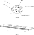
- Figure 7 shows the third implementation mode of the present invention and shows the two fixed blades F3 of the cutter in the third implementation mode of the present invention
- Figure 8 is a side view of part III of the fixed blades F3 shown in Figure 7
- Figure 9 is an enlarged view of part III of the fixed blades F3 shown in Figure 7 .
- Each of the two fixed blades namely, the first fixed blade FF3 and the second fixed blade SF3, of the cutter in the third implementation mode of the present invention has a row of teeth at the front end.
- a clearance is reserved between them and the movable blade can be sandwiched in the clearance.
- the inner surface of the first fixed blade FF3 and the inner surface of the second fixed blade SF3 contact the movable blade to cut hair.
- Each tooth has a fillet on the two sides of the front end to prevent scratching the skin of the user.
- the cross-sections of the teeth of the two fixed blades are isosceles trapezoids, that is to say, a sharp angle is formed between the tooth edges where the two fixed blades contact the movable blade so as to improve the cutting efficiency.
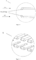
- Figure 10 shows the fourth implementation mode of the present invention and shows the two fixed blades F4 of the cutter in the fourth implementation mode of the present invention
- Figure 11 is a side view of part IV of the fixed blades F4 shown in Figure 10
- Figure 12 is an enlarged view of part IV of the fixed blades F4 shown in Figure 10 .
- Each of the two fixed blades namely, the first fixed blade FF4 and the second fixed blade SF4, of the cutter in the fourth implementation mode of the present invention has a row of teeth at the front end.
- a clearance is reserved between them and the movable blade can be sandwiched in the clearance.
- the inner surface of the first fixed blade FF4 and the inner surface of the second fixed blade SF4 contact the movable blade to cut hair.
- Each tooth has a fillet on the two sides of the front end.
- An arced bulge is formed at the end, far away from the movable blade to be assembled, of each tooth of the two fixed blades to protect the user against any injury caused by the blades during the operation of the cutter.
- the connected portion between the arced bulge and the teeth has also undergone fillet treatment, and therefore it will not injure the user.
- Figure 13 shows the fifth implementation mode of the present invention and shows the two fixed blades F5 of the cutter in the fifth implementation mode of the present invention
- Figure 14 is a side view of part V of the fixed blades F5 shown in Figure 13
- Figure 15 is an enlarged view of part V of the fixed blades F5 shown in Figure 13 .
- the cutter in the fifth embodiment mode of the present invention comprises two fixed blades, namely, a first fixed blade FF5 and a second fixed blade SF5.
- the difference of the fifth implementation mode from the fourth implementation mode is that an arced bulge is formed at the end, near the movable blade to be assembled, of each tooth of the two fixed blades and the bulge can also protect the user against any injury caused by the blades during the operation of the blades.
- the connected portion between the arced bulge and the teeth has also undergone fillet treatment, and therefore it will not injure the user.
- a hair trimmer comprises a driving rocker arm, a blade carrier, and the above-mentioned sandwich-structured cutter, wherein the two fixed blades are fixed on the blade carrier, and the driving rocker arm is pivotably fixed on the blade carrier and drives the movable blade to reciprocate to realize cutting.
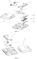
- Figure 16 is an exploded view of one implementation mode of the hair trimmer in the present invention.
- the hair trimmer can comprise a pressure frame 1, a pressure spring 2, an axle sleeve 3, a rocker arm 4 (namely, driving rocker arm), a blade carrier cover 5, a blade carrier 6, and a sandwich-structured cutter consisting of two fixed blades FF and SF and a movable blade M.
- Figure 17 is a partially exploded view of the implementation mode of the hair trimmer shown in Figure 16 .
- the pressure frame 1, the pressure spring 2, and the blade carrier cover 5 are not assembled on the hair trimmer.
- Figure 18 is a partially exploded view of the implementation mode of the hair trimmer shown in Figure 16 .
- one fixed blade FF is not assembled on the hair trimmer.
- Figure 19 shows how the cutter in the present invention cuts hair.
- Figure 19i shows the cross-section of the cutter and there is no hair in the cutter
- Figure 19ii shows a hair in the clearance between three blades
- Figure 19iii shows that the movable blade can be driven by the driving rocker arm to move upward to cut the hair.
Landscapes
- Engineering & Computer Science (AREA)
- Life Sciences & Earth Sciences (AREA)
- Forests & Forestry (AREA)
- Mechanical Engineering (AREA)
- Manufacturing & Machinery (AREA)
- Dry Shavers And Clippers (AREA)
Claims (10)
- Schneideeinrichtung mit Sandwichaufbau, dadurch gekennzeichnet, dass sie umfasst:zwei unbewegliche Messer (FF, SF), die jeweils eine Reihe von Zähnen am vorderen Ende aufweisen, undein bewegliches Messer (M), das sandwichartig zwischen die beiden unbeweglichen Messer (FF, SF) eingefügt ist, sich in Bezug auf die beiden unbeweglichen Messer (FF, SF) in der Längsrichtung hin- und herbewegen kann und ein integriertes Messer ist,wobei das bewegliche Messer (M) eine Reihe von Zähnen am vorderen Ende aufweist, die vorderen Enden der Zähne des beweglichen Messers (M) von den vorderen Enden der Zähne der unbeweglichen Messer (FF, SF) nicht vorstehen, und jeder Zahn des beweglichen Messers (M) eine viereckige Querschnittsform aufweist, die ein erstes Paar paralleler Seiten (FPS) und ein zweites Paar paralleler Seiten (SPS) umfasst, das vier spitze Winkel mit dem ersten Paar Seiten (FPS) bildet.
- Schneideeinrichtung nach Anspruch 1, dadurch gekennzeichnet, dass jede Seite des zweiten Paares (SPS) mindestens eine Aussparung aufweist.
- Schneideeinrichtung nach Anspruch 2, dadurch gekennzeichnet, dass die mindestens eine Aussparung eine abgewinkelte Aussparung umfasst.
- Schneideeinrichtung nach Anspruch 2, dadurch gekennzeichnet, dass die mindestens eine Aussparung eine gewölbte Aussparung umfasst.
- Schneideeinrichtung nach Anspruch 1, dadurch gekennzeichnet, dass die beiden Seiten des zweiten Paares Seiten (SPS) symmetrisch sind.
- Schneideeinrichtung nach Anspruch 1, dadurch gekennzeichnet, dass die Querschnittsform jedes Zahns des beweglichen Messers (M) von der Wurzel zum vorderen Ende des Zahns schrittweise kleiner wird, und die Länge des ersten Paares Seiten (FPS) unverändert bleibt.
- Schneideeinrichtung nach einem der Ansprüche 1 bis 5, dadurch gekennzeichnet, dass mindestens eine Fläche des beweglichen Messers (M) eine Mehrzahl von ausgesparten Abschnitten aufweist, oder das bewegliche Messer (M) eine Mehrzahl von perforierten Löchern (PH1) aufweist.
- Schneideeinrichtung nach einem der Ansprüche 1 bis 5, dadurch gekennzeichnet, dass eine gewölbte Ausbauchung am Ende jedes Zahns der beiden unbeweglichen Messer (FF, SF) weit entfernt vom beweglichen Messer (M) und/oder in der Nähe davon ausgebildet ist.
- Schneideeinrichtung nach einem der Ansprüche 1 bis 5, dadurch gekennzeichnet, dass das Ende jedes Zahns der beiden unbeweglichen Messer (FF, SF) eine Abrundung aufweist.
- Haarschneidegerät, dadurch gekennzeichnet, dass es eine Antriebsschwinge (4), einen Messerträger (6) und die Schneideeinrichtung mit Sandwichaufbau nach einem der Ansprüche 1 bis 9 umfasst, wobei die beiden unbeweglichen Messer (FF, SF) auf dem Messerträger (6) befestigt sind, und die Antriebsschwinge (4) drehbar auf dem Messerträger (6) befestigt ist und das bewegliche Messer (M) zur Hin- und Herbewegung antreibt.
Applications Claiming Priority (1)
| Application Number | Priority Date | Filing Date | Title |
|---|---|---|---|
| CN201710692966.XA CN109382852B (zh) | 2017-08-14 | 2017-08-14 | 夹层式结构的刀具及毛发修剪器 |
Publications (2)
| Publication Number | Publication Date |
|---|---|
| EP3444083A1 EP3444083A1 (de) | 2019-02-20 |
| EP3444083B1 true EP3444083B1 (de) | 2020-04-22 |
Family
ID=63254638
Family Applications (1)
| Application Number | Title | Priority Date | Filing Date |
|---|---|---|---|
| EP18275119.8A Active EP3444083B1 (de) | 2017-08-14 | 2018-08-13 | Messer mit sandwichstruktur und haarschneider |
Country Status (3)
| Country | Link |
|---|---|
| US (1) | US20190047163A1 (de) |
| EP (1) | EP3444083B1 (de) |
| CN (1) | CN109382852B (de) |
Families Citing this family (6)
| Publication number | Priority date | Publication date | Assignee | Title |
|---|---|---|---|---|
| USD1105609S1 (en) | 2022-05-16 | 2025-12-09 | Spectrum Brands, Inc. | Shaver |
| CN115256478B (zh) * | 2022-09-02 | 2026-01-20 | 浙江海顺电工有限公司 | 毛发修剪器的刀片组 |
| CN116766273B (zh) * | 2023-06-29 | 2025-10-24 | 浙江海顺电工有限公司 | 剃毛刀片及其制造方法 |
| CN116766274B (zh) * | 2023-06-29 | 2026-02-27 | 浙江海顺电工有限公司 | 剃毛刀片及其制造方法 |
| CN220279710U (zh) * | 2023-07-25 | 2024-01-02 | 珠海新秀丽家居用品有限公司 | 一种双刀理发剪 |
| CN117774010A (zh) * | 2024-01-09 | 2024-03-29 | 宁波爱克利浦电器有限公司 | 一种电动理发剪 |
Family Cites Families (13)
| Publication number | Priority date | Publication date | Assignee | Title |
|---|---|---|---|---|
| US2233445A (en) * | 1938-04-06 | 1941-03-04 | Andis Mathew | Shaving device |
| US2214069A (en) * | 1939-10-18 | 1940-09-10 | Sikora Edward | Hair clipper |
| US2347869A (en) * | 1940-08-09 | 1944-05-02 | Leon H Amdur | Electric dry shaver |
| JP4032808B2 (ja) * | 2002-04-19 | 2008-01-16 | 松下電工株式会社 | バリカン刃の製造方法 |
| DE502004008237D1 (de) * | 2003-12-04 | 2008-11-20 | Wella Ag | Schneidkopf für eine elektrische haarschneidemaschine |
| US7913399B2 (en) * | 2007-01-14 | 2011-03-29 | Specialife Industries Limited | Blade set for hair clipper |
| US20080209741A1 (en) * | 2007-03-02 | 2008-09-04 | Chin-Chuan Chen | Blade structure of an electric hair trimmer |
| EP2747962B1 (de) * | 2011-11-08 | 2016-09-21 | Koninklijke Philips N.V. | Haarschneidevorrichtung mit verbessertem schneidelement |
| CN202943659U (zh) * | 2012-11-29 | 2013-05-22 | 温州市日电电器有限公司 | 电动理发剪刀头润滑装置 |
| WO2015103248A1 (en) * | 2014-01-01 | 2015-07-09 | Daniel Lawrence Roth | Shaving and grooming apparatus |
| JP6120097B2 (ja) * | 2014-03-31 | 2017-04-26 | パナソニックIpマネジメント株式会社 | バリカン、そのヘッドユニット、および、その可動刃 |
| RU2680324C2 (ru) * | 2014-04-18 | 2019-02-19 | Конинклейке Филипс Н.В. | Ножевой блок, устройство для срезания волос и соответствующий способ изготовления |
| CN106313140A (zh) * | 2016-11-21 | 2017-01-11 | 珠海新秀丽家居用品有限公司 | 一种三文治结构的刀具和采用该刀具的个人护理毛剪 |
-
2017
- 2017-08-14 CN CN201710692966.XA patent/CN109382852B/zh active Active
-
2018
- 2018-08-06 US US16/055,439 patent/US20190047163A1/en not_active Abandoned
- 2018-08-13 EP EP18275119.8A patent/EP3444083B1/de active Active
Non-Patent Citations (1)
| Title |
|---|
| None * |
Also Published As
| Publication number | Publication date |
|---|---|
| EP3444083A1 (de) | 2019-02-20 |
| CN109382852A (zh) | 2019-02-26 |
| US20190047163A1 (en) | 2019-02-14 |
| CN109382852B (zh) | 2021-04-09 |
Similar Documents
| Publication | Publication Date | Title |
|---|---|---|
| EP3444083A1 (de) | Messer mit sandwichstruktur und haarschneider | |
| CN105014703B (zh) | 刀片组、剪发器具以及相关的制造方法 | |
| CN204658474U (zh) | 剪发器具和刀片组 | |
| RU2623532C2 (ru) | Защитный элемент для защиты кожи в машинке для стрижки волос | |
| RU2675414C2 (ru) | Устройство для стрижки волос | |
| KR101499287B1 (ko) | 빗살가드 면도기 카트리지 | |
| US10307919B2 (en) | Sandwich structured cutter and personal hair trimmer using the same | |
| ES2701524T3 (es) | Dispositivo de corte de cabello | |
| RU2721973C1 (ru) | Гребень для машинки для стрижки волос | |
| CN104511919B (zh) | 刀片组和毛发切割器具 | |
| US10016903B2 (en) | Hair clipper comb with magnetic attachment | |
| CN109079862B (zh) | 毛发切割系统和附件 | |
| BRPI0701920A (pt) | escova anexa para máquina de cortar cabelo | |
| RU2008135061A (ru) | Машинка для стрижки волос | |
| IN2012DN05165A (de) | ||
| JP6030763B2 (ja) | ヘアクリッピングデバイス | |
| US20050172490A1 (en) | Double-sided and single-sided shearing devices including ridges | |
| RU2676812C2 (ru) | Устройство для стрижки волос | |
| JP2016500320A (ja) | 毛刈り込み装置のための切断組立体 | |
| RU2016116807A (ru) | Набор лезвий и устройство для стрижки волос | |
| CN100377848C (zh) | 电动剪的蚀刻刀片 | |
| ES2934236T3 (es) | Método de formación de dientes de una hoja de corte o de un protector | |
| JP5879531B2 (ja) | 電気かみそり | |
| CN221850272U (zh) | 一种羊毛修剪用刀片 | |
| RU2774247C1 (ru) | Режущий узел и содержащий его триммер |
Legal Events
| Date | Code | Title | Description |
|---|---|---|---|
| PUAI | Public reference made under article 153(3) epc to a published international application that has entered the european phase |
Free format text: ORIGINAL CODE: 0009012 |
|
| STAA | Information on the status of an ep patent application or granted ep patent |
Free format text: STATUS: THE APPLICATION HAS BEEN PUBLISHED |
|
| AK | Designated contracting states |
Kind code of ref document: A1 Designated state(s): AL AT BE BG CH CY CZ DE DK EE ES FI FR GB GR HR HU IE IS IT LI LT LU LV MC MK MT NL NO PL PT RO RS SE SI SK SM TR |
|
| AX | Request for extension of the european patent |
Extension state: BA ME |
|
| STAA | Information on the status of an ep patent application or granted ep patent |
Free format text: STATUS: REQUEST FOR EXAMINATION WAS MADE |
|
| 17P | Request for examination filed |
Effective date: 20190226 |
|
| RBV | Designated contracting states (corrected) |
Designated state(s): AL AT BE BG CH CY CZ DE DK EE ES FI FR GB GR HR HU IE IS IT LI LT LU LV MC MK MT NL NO PL PT RO RS SE SI SK SM TR |
|
| GRAP | Despatch of communication of intention to grant a patent |
Free format text: ORIGINAL CODE: EPIDOSNIGR1 |
|
| STAA | Information on the status of an ep patent application or granted ep patent |
Free format text: STATUS: GRANT OF PATENT IS INTENDED |
|
| INTG | Intention to grant announced |
Effective date: 20191114 |
|
| GRAS | Grant fee paid |
Free format text: ORIGINAL CODE: EPIDOSNIGR3 |
|
| GRAA | (expected) grant |
Free format text: ORIGINAL CODE: 0009210 |
|
| STAA | Information on the status of an ep patent application or granted ep patent |
Free format text: STATUS: THE PATENT HAS BEEN GRANTED |
|
| AK | Designated contracting states |
Kind code of ref document: B1 Designated state(s): AL AT BE BG CH CY CZ DE DK EE ES FI FR GB GR HR HU IE IS IT LI LT LU LV MC MK MT NL NO PL PT RO RS SE SI SK SM TR |
|
| REG | Reference to a national code |
Ref country code: CH Ref legal event code: EP |
|
| REG | Reference to a national code |
Ref country code: IE Ref legal event code: FG4D |
|
| REG | Reference to a national code |
Ref country code: DE Ref legal event code: R096 Ref document number: 602018004000 Country of ref document: DE |
|
| REG | Reference to a national code |
Ref country code: AT Ref legal event code: REF Ref document number: 1259467 Country of ref document: AT Kind code of ref document: T Effective date: 20200515 |
|
| REG | Reference to a national code |
Ref country code: LT Ref legal event code: MG4D |
|
| REG | Reference to a national code |
Ref country code: NL Ref legal event code: MP Effective date: 20200422 |
|
| PG25 | Lapsed in a contracting state [announced via postgrant information from national office to epo] |
Ref country code: NO Free format text: LAPSE BECAUSE OF FAILURE TO SUBMIT A TRANSLATION OF THE DESCRIPTION OR TO PAY THE FEE WITHIN THE PRESCRIBED TIME-LIMIT Effective date: 20200722 Ref country code: PT Free format text: LAPSE BECAUSE OF FAILURE TO SUBMIT A TRANSLATION OF THE DESCRIPTION OR TO PAY THE FEE WITHIN THE PRESCRIBED TIME-LIMIT Effective date: 20200824 Ref country code: FI Free format text: LAPSE BECAUSE OF FAILURE TO SUBMIT A TRANSLATION OF THE DESCRIPTION OR TO PAY THE FEE WITHIN THE PRESCRIBED TIME-LIMIT Effective date: 20200422 Ref country code: LT Free format text: LAPSE BECAUSE OF FAILURE TO SUBMIT A TRANSLATION OF THE DESCRIPTION OR TO PAY THE FEE WITHIN THE PRESCRIBED TIME-LIMIT Effective date: 20200422 Ref country code: SE Free format text: LAPSE BECAUSE OF FAILURE TO SUBMIT A TRANSLATION OF THE DESCRIPTION OR TO PAY THE FEE WITHIN THE PRESCRIBED TIME-LIMIT Effective date: 20200422 Ref country code: IS Free format text: LAPSE BECAUSE OF FAILURE TO SUBMIT A TRANSLATION OF THE DESCRIPTION OR TO PAY THE FEE WITHIN THE PRESCRIBED TIME-LIMIT Effective date: 20200822 Ref country code: GR Free format text: LAPSE BECAUSE OF FAILURE TO SUBMIT A TRANSLATION OF THE DESCRIPTION OR TO PAY THE FEE WITHIN THE PRESCRIBED TIME-LIMIT Effective date: 20200723 Ref country code: NL Free format text: LAPSE BECAUSE OF FAILURE TO SUBMIT A TRANSLATION OF THE DESCRIPTION OR TO PAY THE FEE WITHIN THE PRESCRIBED TIME-LIMIT Effective date: 20200422 |
|
| REG | Reference to a national code |
Ref country code: AT Ref legal event code: MK05 Ref document number: 1259467 Country of ref document: AT Kind code of ref document: T Effective date: 20200422 |
|
| PG25 | Lapsed in a contracting state [announced via postgrant information from national office to epo] |
Ref country code: RS Free format text: LAPSE BECAUSE OF FAILURE TO SUBMIT A TRANSLATION OF THE DESCRIPTION OR TO PAY THE FEE WITHIN THE PRESCRIBED TIME-LIMIT Effective date: 20200422 Ref country code: LV Free format text: LAPSE BECAUSE OF FAILURE TO SUBMIT A TRANSLATION OF THE DESCRIPTION OR TO PAY THE FEE WITHIN THE PRESCRIBED TIME-LIMIT Effective date: 20200422 Ref country code: HR Free format text: LAPSE BECAUSE OF FAILURE TO SUBMIT A TRANSLATION OF THE DESCRIPTION OR TO PAY THE FEE WITHIN THE PRESCRIBED TIME-LIMIT Effective date: 20200422 Ref country code: BG Free format text: LAPSE BECAUSE OF FAILURE TO SUBMIT A TRANSLATION OF THE DESCRIPTION OR TO PAY THE FEE WITHIN THE PRESCRIBED TIME-LIMIT Effective date: 20200722 |
|
| PG25 | Lapsed in a contracting state [announced via postgrant information from national office to epo] |
Ref country code: AL Free format text: LAPSE BECAUSE OF FAILURE TO SUBMIT A TRANSLATION OF THE DESCRIPTION OR TO PAY THE FEE WITHIN THE PRESCRIBED TIME-LIMIT Effective date: 20200422 |
|
| REG | Reference to a national code |
Ref country code: DE Ref legal event code: R097 Ref document number: 602018004000 Country of ref document: DE |
|
| PG25 | Lapsed in a contracting state [announced via postgrant information from national office to epo] |
Ref country code: ES Free format text: LAPSE BECAUSE OF FAILURE TO SUBMIT A TRANSLATION OF THE DESCRIPTION OR TO PAY THE FEE WITHIN THE PRESCRIBED TIME-LIMIT Effective date: 20200422 Ref country code: DK Free format text: LAPSE BECAUSE OF FAILURE TO SUBMIT A TRANSLATION OF THE DESCRIPTION OR TO PAY THE FEE WITHIN THE PRESCRIBED TIME-LIMIT Effective date: 20200422 Ref country code: SM Free format text: LAPSE BECAUSE OF FAILURE TO SUBMIT A TRANSLATION OF THE DESCRIPTION OR TO PAY THE FEE WITHIN THE PRESCRIBED TIME-LIMIT Effective date: 20200422 Ref country code: IT Free format text: LAPSE BECAUSE OF FAILURE TO SUBMIT A TRANSLATION OF THE DESCRIPTION OR TO PAY THE FEE WITHIN THE PRESCRIBED TIME-LIMIT Effective date: 20200422 Ref country code: AT Free format text: LAPSE BECAUSE OF FAILURE TO SUBMIT A TRANSLATION OF THE DESCRIPTION OR TO PAY THE FEE WITHIN THE PRESCRIBED TIME-LIMIT Effective date: 20200422 Ref country code: CZ Free format text: LAPSE BECAUSE OF FAILURE TO SUBMIT A TRANSLATION OF THE DESCRIPTION OR TO PAY THE FEE WITHIN THE PRESCRIBED TIME-LIMIT Effective date: 20200422 Ref country code: EE Free format text: LAPSE BECAUSE OF FAILURE TO SUBMIT A TRANSLATION OF THE DESCRIPTION OR TO PAY THE FEE WITHIN THE PRESCRIBED TIME-LIMIT Effective date: 20200422 Ref country code: RO Free format text: LAPSE BECAUSE OF FAILURE TO SUBMIT A TRANSLATION OF THE DESCRIPTION OR TO PAY THE FEE WITHIN THE PRESCRIBED TIME-LIMIT Effective date: 20200422 |
|
| PG25 | Lapsed in a contracting state [announced via postgrant information from national office to epo] |
Ref country code: PL Free format text: LAPSE BECAUSE OF FAILURE TO SUBMIT A TRANSLATION OF THE DESCRIPTION OR TO PAY THE FEE WITHIN THE PRESCRIBED TIME-LIMIT Effective date: 20200422 Ref country code: SK Free format text: LAPSE BECAUSE OF FAILURE TO SUBMIT A TRANSLATION OF THE DESCRIPTION OR TO PAY THE FEE WITHIN THE PRESCRIBED TIME-LIMIT Effective date: 20200422 |
|
| PLBE | No opposition filed within time limit |
Free format text: ORIGINAL CODE: 0009261 |
|
| STAA | Information on the status of an ep patent application or granted ep patent |
Free format text: STATUS: NO OPPOSITION FILED WITHIN TIME LIMIT |
|
| 26N | No opposition filed |
Effective date: 20210125 |
|
| PG25 | Lapsed in a contracting state [announced via postgrant information from national office to epo] |
Ref country code: MC Free format text: LAPSE BECAUSE OF FAILURE TO SUBMIT A TRANSLATION OF THE DESCRIPTION OR TO PAY THE FEE WITHIN THE PRESCRIBED TIME-LIMIT Effective date: 20200422 |
|
| PG25 | Lapsed in a contracting state [announced via postgrant information from national office to epo] |
Ref country code: LU Free format text: LAPSE BECAUSE OF NON-PAYMENT OF DUE FEES Effective date: 20200813 |
|
| REG | Reference to a national code |
Ref country code: BE Ref legal event code: MM Effective date: 20200831 |
|
| PG25 | Lapsed in a contracting state [announced via postgrant information from national office to epo] |
Ref country code: SI Free format text: LAPSE BECAUSE OF FAILURE TO SUBMIT A TRANSLATION OF THE DESCRIPTION OR TO PAY THE FEE WITHIN THE PRESCRIBED TIME-LIMIT Effective date: 20200422 |
|
| PG25 | Lapsed in a contracting state [announced via postgrant information from national office to epo] |
Ref country code: FR Free format text: LAPSE BECAUSE OF NON-PAYMENT OF DUE FEES Effective date: 20200831 |
|
| PG25 | Lapsed in a contracting state [announced via postgrant information from national office to epo] |
Ref country code: BE Free format text: LAPSE BECAUSE OF NON-PAYMENT OF DUE FEES Effective date: 20200831 Ref country code: IE Free format text: LAPSE BECAUSE OF NON-PAYMENT OF DUE FEES Effective date: 20200813 |
|
| PGFP | Annual fee paid to national office [announced via postgrant information from national office to epo] |
Ref country code: DE Payment date: 20210322 Year of fee payment: 4 |
|
| REG | Reference to a national code |
Ref country code: CH Ref legal event code: PL |
|
| PG25 | Lapsed in a contracting state [announced via postgrant information from national office to epo] |
Ref country code: LI Free format text: LAPSE BECAUSE OF NON-PAYMENT OF DUE FEES Effective date: 20210831 Ref country code: CH Free format text: LAPSE BECAUSE OF NON-PAYMENT OF DUE FEES Effective date: 20210831 |
|
| PG25 | Lapsed in a contracting state [announced via postgrant information from national office to epo] |
Ref country code: TR Free format text: LAPSE BECAUSE OF FAILURE TO SUBMIT A TRANSLATION OF THE DESCRIPTION OR TO PAY THE FEE WITHIN THE PRESCRIBED TIME-LIMIT Effective date: 20200422 Ref country code: MT Free format text: LAPSE BECAUSE OF FAILURE TO SUBMIT A TRANSLATION OF THE DESCRIPTION OR TO PAY THE FEE WITHIN THE PRESCRIBED TIME-LIMIT Effective date: 20200422 Ref country code: CY Free format text: LAPSE BECAUSE OF FAILURE TO SUBMIT A TRANSLATION OF THE DESCRIPTION OR TO PAY THE FEE WITHIN THE PRESCRIBED TIME-LIMIT Effective date: 20200422 |
|
| PG25 | Lapsed in a contracting state [announced via postgrant information from national office to epo] |
Ref country code: MK Free format text: LAPSE BECAUSE OF FAILURE TO SUBMIT A TRANSLATION OF THE DESCRIPTION OR TO PAY THE FEE WITHIN THE PRESCRIBED TIME-LIMIT Effective date: 20200422 |
|
| REG | Reference to a national code |
Ref country code: DE Ref legal event code: R119 Ref document number: 602018004000 Country of ref document: DE |
|
| GBPC | Gb: european patent ceased through non-payment of renewal fee |
Effective date: 20220813 |
|
| PG25 | Lapsed in a contracting state [announced via postgrant information from national office to epo] |
Ref country code: DE Free format text: LAPSE BECAUSE OF NON-PAYMENT OF DUE FEES Effective date: 20230301 |
|
| PG25 | Lapsed in a contracting state [announced via postgrant information from national office to epo] |
Ref country code: GB Free format text: LAPSE BECAUSE OF NON-PAYMENT OF DUE FEES Effective date: 20220813 |