EP3444106A1 - Fabrication de composites basés sur une matrice - Google Patents
Fabrication de composites basés sur une matrice Download PDFInfo
- Publication number
- EP3444106A1 EP3444106A1 EP18168952.2A EP18168952A EP3444106A1 EP 3444106 A1 EP3444106 A1 EP 3444106A1 EP 18168952 A EP18168952 A EP 18168952A EP 3444106 A1 EP3444106 A1 EP 3444106A1
- Authority
- EP
- European Patent Office
- Prior art keywords
- die
- tape
- laminates
- gap filler
- continuous
- Prior art date
- Legal status (The legal status is an assumption and is not a legal conclusion. Google has not performed a legal analysis and makes no representation as to the accuracy of the status listed.)
- Granted
Links
Images



Classifications
-
- B—PERFORMING OPERATIONS; TRANSPORTING
- B29—WORKING OF PLASTICS; WORKING OF SUBSTANCES IN A PLASTIC STATE IN GENERAL
- B29C—SHAPING OR JOINING OF PLASTICS; SHAPING OF MATERIAL IN A PLASTIC STATE, NOT OTHERWISE PROVIDED FOR; AFTER-TREATMENT OF THE SHAPED PRODUCTS, e.g. REPAIRING
- B29C70/00—Shaping composites, i.e. plastics material comprising reinforcements, fillers or preformed parts, e.g. inserts
- B29C70/04—Shaping composites, i.e. plastics material comprising reinforcements, fillers or preformed parts, e.g. inserts comprising reinforcements only, e.g. self-reinforcing plastics
- B29C70/28—Shaping operations therefor
- B29C70/40—Shaping or impregnating by compression not applied
- B29C70/50—Shaping or impregnating by compression not applied for producing articles of indefinite length, e.g. prepregs, sheet moulding compounds [SMC] or cross moulding compounds [XMC]
- B29C70/52—Pultrusion, i.e. forming and compressing by continuously pulling through a die
- B29C70/525—Component parts, details or accessories; Auxiliary operations
- B29C70/526—Pultrusion dies, e.g. dies with moving or rotating parts
-
- B—PERFORMING OPERATIONS; TRANSPORTING
- B29—WORKING OF PLASTICS; WORKING OF SUBSTANCES IN A PLASTIC STATE IN GENERAL
- B29C—SHAPING OR JOINING OF PLASTICS; SHAPING OF MATERIAL IN A PLASTIC STATE, NOT OTHERWISE PROVIDED FOR; AFTER-TREATMENT OF THE SHAPED PRODUCTS, e.g. REPAIRING
- B29C43/00—Compression moulding, i.e. applying external pressure to flow the moulding material; Apparatus therefor
- B29C43/22—Compression moulding, i.e. applying external pressure to flow the moulding material; Apparatus therefor of articles of indefinite length
- B29C43/28—Compression moulding, i.e. applying external pressure to flow the moulding material; Apparatus therefor of articles of indefinite length incorporating preformed parts or layers, e.g. compression moulding around inserts or for coating articles
-
- B—PERFORMING OPERATIONS; TRANSPORTING
- B29—WORKING OF PLASTICS; WORKING OF SUBSTANCES IN A PLASTIC STATE IN GENERAL
- B29C—SHAPING OR JOINING OF PLASTICS; SHAPING OF MATERIAL IN A PLASTIC STATE, NOT OTHERWISE PROVIDED FOR; AFTER-TREATMENT OF THE SHAPED PRODUCTS, e.g. REPAIRING
- B29C70/00—Shaping composites, i.e. plastics material comprising reinforcements, fillers or preformed parts, e.g. inserts
- B29C70/04—Shaping composites, i.e. plastics material comprising reinforcements, fillers or preformed parts, e.g. inserts comprising reinforcements only, e.g. self-reinforcing plastics
- B29C70/28—Shaping operations therefor
- B29C70/40—Shaping or impregnating by compression not applied
- B29C70/50—Shaping or impregnating by compression not applied for producing articles of indefinite length, e.g. prepregs, sheet moulding compounds [SMC] or cross moulding compounds [XMC]
-
- B—PERFORMING OPERATIONS; TRANSPORTING
- B29—WORKING OF PLASTICS; WORKING OF SUBSTANCES IN A PLASTIC STATE IN GENERAL
- B29C—SHAPING OR JOINING OF PLASTICS; SHAPING OF MATERIAL IN A PLASTIC STATE, NOT OTHERWISE PROVIDED FOR; AFTER-TREATMENT OF THE SHAPED PRODUCTS, e.g. REPAIRING
- B29C70/00—Shaping composites, i.e. plastics material comprising reinforcements, fillers or preformed parts, e.g. inserts
- B29C70/04—Shaping composites, i.e. plastics material comprising reinforcements, fillers or preformed parts, e.g. inserts comprising reinforcements only, e.g. self-reinforcing plastics
- B29C70/28—Shaping operations therefor
- B29C70/40—Shaping or impregnating by compression not applied
- B29C70/50—Shaping or impregnating by compression not applied for producing articles of indefinite length, e.g. prepregs, sheet moulding compounds [SMC] or cross moulding compounds [XMC]
- B29C70/52—Pultrusion, i.e. forming and compressing by continuously pulling through a die
- B29C70/521—Pultrusion, i.e. forming and compressing by continuously pulling through a die and impregnating the reinforcement before the die
-
- B—PERFORMING OPERATIONS; TRANSPORTING
- B29—WORKING OF PLASTICS; WORKING OF SUBSTANCES IN A PLASTIC STATE IN GENERAL
- B29D—PRODUCING PARTICULAR ARTICLES FROM PLASTICS OR FROM SUBSTANCES IN A PLASTIC STATE
- B29D99/00—Subject matter not provided for in other groups of this subclass
- B29D99/0003—Producing profiled members, e.g. beams
- B29D99/0005—Producing noodles, i.e. composite gap fillers, characterised by their construction
-
- B—PERFORMING OPERATIONS; TRANSPORTING
- B29—WORKING OF PLASTICS; WORKING OF SUBSTANCES IN A PLASTIC STATE IN GENERAL
- B29C—SHAPING OR JOINING OF PLASTICS; SHAPING OF MATERIAL IN A PLASTIC STATE, NOT OTHERWISE PROVIDED FOR; AFTER-TREATMENT OF THE SHAPED PRODUCTS, e.g. REPAIRING
- B29C43/00—Compression moulding, i.e. applying external pressure to flow the moulding material; Apparatus therefor
- B29C43/32—Component parts, details or accessories; Auxiliary operations
- B29C43/52—Heating or cooling
-
- B—PERFORMING OPERATIONS; TRANSPORTING
- B29—WORKING OF PLASTICS; WORKING OF SUBSTANCES IN A PLASTIC STATE IN GENERAL
- B29K—INDEXING SCHEME ASSOCIATED WITH SUBCLASSES B29B, B29C OR B29D, RELATING TO MOULDING MATERIALS OR TO MATERIALS FOR MOULDS, REINFORCEMENTS, FILLERS OR PREFORMED PARTS, e.g. INSERTS
- B29K2105/00—Condition, form or state of moulded material or of the material to be shaped
- B29K2105/06—Condition, form or state of moulded material or of the material to be shaped containing reinforcements, fillers or inserts
-
- B—PERFORMING OPERATIONS; TRANSPORTING
- B29—WORKING OF PLASTICS; WORKING OF SUBSTANCES IN A PLASTIC STATE IN GENERAL
- B29K—INDEXING SCHEME ASSOCIATED WITH SUBCLASSES B29B, B29C OR B29D, RELATING TO MOULDING MATERIALS OR TO MATERIALS FOR MOULDS, REINFORCEMENTS, FILLERS OR PREFORMED PARTS, e.g. INSERTS
- B29K2307/00—Use of elements other than metals as reinforcement
- B29K2307/04—Carbon
Definitions
- the disclosure relates to the field of composite part fabrication.
- CFRP Carbon Fiber Reinforced Polymer
- Continuous Compression Molding (CCM) machines may be utilized to fabricate continuous-length thermoplastic composite parts having complex cross-sectional shapes (e.g., "I,” “C,” “H,” etc.).
- CCM machine When a CCM machine forms a thermoplastic composite part, it is not uncommon for the CCM machine to receive multiple laminates and apply bends to the laminates. The CCM machine may further apply heat, and press the laminates together to form a composite part.
- long or continuous lengths of laminates may be fed through a pre-forming operation wherein the laminates are shaped into a continuous pre-form. The pre-form is then passed to a compression press that performs heating and consolidation.
- the consolidation operation includes iteratively operating dynamic dies which forces the plies together and consolidates the plies into a final shape. The dies then retract in order to enable the laminate to advance.
- laminates comprise multiple layers and have a non-zero thickness
- bends applied to laminates may result in gaps when laminates are consolidated, which results in reduced structural strength.
- designers of composite parts continue to seek out enhanced techniques for filling gaps in complex thermoplastic composite parts formed by CCM machines.
- Embodiments described herein provide for enhanced dies for fabrication of composite parts.
- CCM machines may integrate gap fillers created by these dies into CCM fabrication techniques for composite parts.
- a drive mechanism of a CCM machine may be integrated with one or more heated dies that shape incoming fiber reinforced tape into a desired cross-sectional shape for a gap filler.
- operation of the CCM machine serves to pull laminates forward for shaping, and also pulls tape through the dies to facilitate pre-forming during CCM operations. This ensures that the gap fillers exhibit and maintain a desired shape both before and after pre-forming operations.
- One embodiment is a method that includes receiving flat unidirectional tape that is continuous and fiber-reinforced, and drawing the tape through a fixed die that heats and plastically deforms the tape into a gap filler having a non-flat cross section.
- a further embodiment is an apparatus.
- the apparatus includes a fixed reinforced thermoplastic material forming die.
- the die includes a body comprising a channel having a first cross section at an entrance and a second cross section at an exit that is smaller than the first cross section and a heater contacting the body, the heater comprising multiple heating elements that heat the body to a glass transition temperature for a reinforced thermoplastic material.
- a pulling mechanism downstream of the die draws the reinforced thermoplastic material through the die.
- a feeding device upstream of the die feeds the reinforced thermoplastic material into the entrance.
- a further embodiment is a system that includes laminates that are continuous and fiber-reinforced, flat unidirectional tape that is continuous and fiber-reinforced, and a fixed die that receives the tape, heats the tape, and plastically deforms the tape into a gap filler having a non-flat cross-section.
- a still further embodiment is a non-transitory computer readable medium embodying programmed instructions which, when executed by a processor, are operable for performing a method.
- the method includes receiving flat unidirectional tape that is continuous and fiber-reinforced, and drawing the tape through a fixed die that heats and plastically deforms the tape into a gap filler having a non-flat cross section.
- FIG. 1 is a block diagram of a CCM machine 100 that includes fixed dies 194 for forming gap fillers in an exemplary embodiment.
- CCM machine 100 includes preformer 120 and consolidator 130.
- Plies 112 of fiber-reinforced material e.g., Carbon Fiber Reinforced Polymer (CFRP)
- CFRP Carbon Fiber Reinforced Polymer
- release foils 116 are supplied to facilitate the shaping process.
- Plies 112 and release foils 116 are fed to preformer 120.
- Plies 112 that are part of the same laminate at preformer 120 are referred to as "laminates.”
- Gap fillers 174 are also illustrated in FIG. 1 .
- Gap fillers 174 are shaped from tape 172 (e.g., a fiber reinforced unidirectional material) by travelling through fixed dies 194.
- Guides 118 facilitate entry of plies 112 and gap fillers 174 into preformer 120.
- preformer 120 various shape features may be preformed via the application of pressure to plies 112 and gap fillers 174.
- tape 172 progresses through fixed dies 194 to become gap fillers 174 as part of a pultrusion process, and then is introduced into CCM processes that involve incremental shaping/forming.
- Preformer 120 shapes plies 112 and gap filler 174 into a preformed laminate 122.
- Preformed laminate 122 has the general shape of composite part 138, but has not yet been consolidated.
- Preformed laminate 122 exits preformer 120 and moves into consolidator 130.
- Consolidator 130 includes a plurality of dynamic dies 136 (e.g., moving dies). Dynamic dies 136 shape preformed laminate 122 during consolidation.
- Consolidator 130 further includes drive mechanism 140 (e.g., a pulsating drive mechanism, such as a set of periodically driven rollers, etc.) that moves preformed laminate 122 forward within consolidator 130 and away from preformer 120, in continuous, incremental steps.
- drive mechanism 140 e.g., a pulsating drive mechanism, such as a set of periodically driven rollers, etc.
- the preformed laminate 122 first enters a heating zone 126 that heats preformed laminate 122 to a temperature which allows the free flow of the polymeric component of a curable resin in plies 112.
- heating zone 126 may heat preformed laminate to a glass transition temperature of the resin, such as 700° Fahrenheit (F).
- preformed laminate 122 moves forward into a pressing zone 132 wherein dynamic dies 136 are brought down collectively or individually at predefined pressures sufficient to compress and consolidate (i.e., allow free-flow of matrix resin within) the various plies 112, resulting in a desired shape and thickness.
- Actuators 128 provide force that engages and withdraws dynamic dies 136.
- preformed laminate 122 is incrementally advanced within consolidator 130, following which dynamic dies 136 are closed again, causing successive portions of the preformed laminate 122 to be compressed within different temperature zones, and thereby consolidate plies 112 in the compressed section. This process is repeated for each temperature zone of dynamic dies 136 as preformed laminate 122 is incrementally advanced through consolidator 130.
- the fully formed and compressed preformed laminate 122 then enters a cooling zone 134 which is separated from the pressing zone 132, wherein the temperature is brought below the free-flowing temperature of the curable resin in plies 112 thereby causing the fused and/or consolidated preformed laminate 122 to harden into a final shape.
- the consolidated and cooled composite part 138 then exits consolidator 130, where release foils 116 are taken up on rollers 142.
- the final composite part 144 is removed at the end of CCM machine 100.
- Controller 196 manages the operations of CCM machine 100.
- controller 196 may control timing and/or amounts of force applied by drive mechanism 140, preformer 120, actuators 128, and/or dynamic dies 136.
- controller 196 manages pultrusion operations at fixed dies 194, as well as the speed of CCM operations.
- controller 196 may control an amount of force in response to input from one or more tension sensors (not shown), and may time the operations of drive mechanism 140 to ensure that drive mechanism pulls while dynamic dies 136 are not engaged.
- Controller 196 may be implemented, for example, as custom circuitry, as a hardware processor executing programmed instructions, or some combination thereof.
- FIG. 2 is a front view of a cross-section of laminates about to be shaped by a CCM machine in an exemplary embodiment. Specifically, FIG. 2 corresponds with view arrows 2 of FIG. 1 .
- FIG. 2 shows laminates prior to forming into an "I" beam 200 of back-to-back "C" channels 250, wherein gap fillers 174 are sandwiched between the C channels 250.
- FIG. 2 does not show release foils 116
- laminates 220 are horizontally oriented and each comprise multiple layers 222, while laminates 210 are vertically oriented and each comprise layers 212. Gap fillers 174 are also illustrated. Before entering preformer 120, laminates 210 and laminates 220 are planar.
- FIG. 3 is a perspective view of the shaping of laminates performed by preformer 120, and corresponds with view arrows 3 of FIG. 1 .
- layers 222 of laminates 220 are folded to form "C" channels, while layers 212 of laminates 210 are arranged to vertically couple laminates 220 together.
- C-shaped mandrels 310 are also illustrated.
- Gap fillers 174 are arranged to fit within gaps that would otherwise be formed by the bending of laminates 220.
- FIG. 4 is a front view of a dynamic die 136 of a CCM machine that is not presently loaded with laminates and gap fillers in an exemplary embodiment.
- FIG. 4 corresponds with view arrows 4 of FIG. 1 , and illustrates that dynamic dies 136 may include dies 420, and dies 410.
- dies 410 exhibit a tool radius 412. Dies 410 and dies 420 apply force (F) that consolidates laminates 210 and laminates 220 into an "H" shaped cross section.
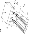
- FIG. 5 is an isometric view of laminates 210, laminates 220, and gap fillers 174 entering a consolidator 130 of CCM machine 100 in an exemplary embodiment.
- FIG. 5 corresponds with view arrows 5 of FIG. 4 .
- FIG. 5 illustrates that laminates 210 leave forming tool 510 of preformer 120.
- Laminates 220 are arranged into "C" channels by interaction of forming tools 520 and C-channel shaped forming tool 530 of preformer 120.
- gap fillers 174 exit guides 570 of preformer 120.
- Laminates 210, laminates 220, gap fillers 174, and release foils 116 cross region 540 before entering consolidator 130.
- gap fillers 174 merely comprised a single rolled up or spiraled layer of material, gap fillers 174 could potentially unroll within this region due to ambient elastic forces in region 540. This in turn would change the cross-sectional area of gap fillers 174, resulting in a distortion or bulge at the resulting composite part. Fortunately, gap fillers 174 have been heated above a glass transition temperature and pulled through fixed dies 194 prior to entry into preformer 120. This means that gap fillers 174 have no internal stresses which would cause them to deform during travel through region 540.
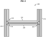
- FIG. 6 is a slightly exploded front view of a cross section 600 of a composite part 138 that has been shaped by CCM machine 100 in an exemplary embodiment, and is not drawn to scale.
- FIG. 6 corresponds with view arrows 6 of FIG. 1 , which illustrates a cross-section after consolidation has been completed. As shown in FIG.
- laminates 220 and laminates 210 have been consolidated to form back-to-back C channels that define an "I.”
- gap fillers 174 have been consolidated into the "I” in order to account for a bend radius 620 that would otherwise result in gaps at the "I.”
- Bend radius 610 is also illustrated, but does not form a gap because it is external to the "I.”
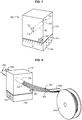
- FIGS. 7-8 are diagrams illustrating a fixed die 700 for shaping unidirectional fiber reinforced tape 820 into a gap filler 830 of CCM machine 100 in an exemplary embodiment. Both FIG. 7 and FIG. 8 correspond with view arrows 7 of FIG. 1 , with the exception that gap fillers 174 have been omitted from FIG. 7 .
- FIG. 7 illustrates that fixed die 700 includes body 710.
- Body 710 includes channel 730 having an entrance 721 with a first cross section 720.
- Channel 730 also has an exit 723 having a second cross section 722, which corresponds with a (non-flat) cross section of a gap that would otherwise exist within the final "I" shaped composite part formed by CCM machine 100.
- FIG. 7 further illustrates that fixed die 700 is heated by heater 740, which in this embodiment comprises a resistive heater that contacts body 710 and has multiple heating elements 742 (e.g., electrically resistive heating elements) that heat body 710.
- a heat sensor 750 measures a temperature of die 700 (e.g., body 710).
- FIG. 8 illustrates that during CCM operations, tape 820 is unwound from spool 810, and drawn through channel 730 to match cross section 720. As gap filler 174 is pulled through channel 730, it is further condensed to conform with cross section 722 which is an exit of channel 730.
- This tapering of channel 730 helps to force tape into a desired cross section with a tapered transition.
- a completed gap filler 830 then exits fixed die 700. Hence, additional folding/overlapping of tape occurs during the forming and consolidation process of tape 820 into gap filler 830.
- One or more tension sensors 850 are also provided to ensure that tension stays within an expected range, and/or does not exceed a predefined value. Controller 196 may utilize input from these sensors to engage in a feedback control loop.
- a pulling mechanism downstream of die 700 such as drive mechanism 140, pulls the gap filler draws reinforced thermoplastic fiber material out of die 700.
- a feeding device upstream of the die e.g., spool 810) feeds the reinforced thermoplastic material into entrance 721.
- CCM machine 100 Illustrative details of the operation of CCM machine 100 will be further discussed with regard to FIG. 9 . Assume, for this embodiment, that CCM machine 100 is loaded with laminates and gap fillers and is presently engaged in the fabrication of a continuous-length composite part.
- FIG. 9 is a flowchart illustrating a method 900 for operating a CCM machine in an exemplary embodiment.
- the steps of method 900 are described with reference to CCM machine 100 of FIG. 1 , but those skilled in the art will appreciate that method 900 may be performed in other systems.
- the steps of the flowcharts described herein are not all inclusive and may include other steps not shown. The steps described herein may also be performed in an alternative order.
- CCM machine 100 receives laminates 210 and laminates 220 (step 902).
- Laminates 210 and laminates 220 are continuous and fiber reinforced. Furthermore, each layer of laminates 210 and laminates 220 may exhibit a different fiber orientation.
- CCM machine 100 also receives tape 172 which is continuous and reinforced by a unidirectional fiber. Tape 172, and the laminates, may be received via large spools (not shown).
- Method 900 further includes drawing tape 172 through a fixed die 194, thereby plastically deforming tape 172 into a desired cross section 722 (step 906).
- Fixed die 194 is heated, and the combination of heat and pressure applied by drawing tape 172 through fixed die 194 causes thermoplastic material within tape 172 to melt as it is drawn through fixed die 194.
- the thermoplastic material solidifies having a cross section defined by fixed die 194, and forms gap filler 174. Since gap filler 174 has been formed by heated pultrusion through fixed die 194 means that internal stresses within gap filler 174 are reset after gap filler 174 is formed.
- gap filler 174 does not unwind or uncoil when it travels from preformer 120 to consolidator 130.
- a distance between fixed die 194 and preformer 120 may be selected specifically to ensure that gap filler 174 finishes solidifying before gap filler 170 reaches preformer 120.
- One or more gap fillers 174, laminates 210, and laminates 220 are arranged at preformer 120, which is downstream of fixed dies 194 (step 908). During this arrangement, one or more laminates are folded into a desired shape, but are not yet consolidated onto other laminates.
- Controller 196 operates dynamic dies 136 and actuators 128 in order to iteratively engage and disengage one or more dynamic dies 136 (step 910).
- Engaging the dynamic die 136 compresses laminates 210, laminates 220, and gap fillers 174. Heating of these components to a desired temperature (e.g., 700° F) melts thermoplastic within these components. Hence, after cooling an integral continuous composite part 138 has been formed.
- Composite part 138 has cross section 600 (e.g., as illustrated at FIG. 6 ). Withdrawing dynamic dies 136 releases a brake on the advancement of final composite part 144, which in turn enables continuous composite part 138 to advance downstream by operation of drive mechanism 140.
- controller 196 directs drive mechanism 140 to pull composite part 138 downstream (step 912). This draws gap fillers 174, laminates 210, and laminates 220 through preformer 120 and consolidator 130 (including dynamic dies 136). The action also draws tape 172 through fixed die 194.
- Drive mechanism 140 may be stopped while dynamic dies 136 are engaged, and started while dynamic dies 136 are withdrawn. Hence, the same drive mechanism 140 that performs CCM operations performs pultrusion in order to form gap fillers used in those same CCM operations.
- drive mechanism 140 draws laminates 210, laminates 220, and gap fillers 174 through preformer 120 and dynamic die 136, while also drawing tape 172 through fixed die 194. These processes are controlled by controller 196.
- Utilizing method 900 provides a substantial advantage in that it blends pultrusion techniques for gap fillers seamlessly into a CCM machine. It prevents gap fillers 174 from unwinding or uncoiling as they transition from preformer 120 to consolidator 130, and furthermore enable a drive mechanism 140 at CCM machine 100 to be utilized for multiple purposes, increasing efficiency.
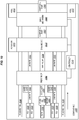
- FIG. 10 is a block diagram of a CCM machine 1000 in an exemplary embodiment.
- controller 1010 e.g., a processor implementing instructions
- Incoming plies 1020 are combined to form laminates 1022, which are directed by guides 1040 into preformer 1060.
- Release foil 1030 is also directed into preformer 1060.
- Tape 1050 is drawn through fixed die 1052, which is heated by heater 1053. This results in gap filler 1054 having a desired cross section. Gap filler 1054 also enters preformer 1060, which arranges these various input to approximate a cross section for the resulting composite part 1080.
- Laminates 1022, release foils 1030, and gap filler 1054 enter dynamic die 1070, which is driven by actuator 1072 to consolidate these components at an elevated temperature wherein thermoplastic within these components melts.
- actuator 1072 Upon cooling and solidifying, composite part 1080 is formed.
- Drive mechanism 1090 draws composite part 1080 and release foil 1030 forward while dynamic die 1070 is not engaged, in order to enable continued fabrication of a length of composite part 1080. Release foil 1030 is then stored on roll 1032.
- exemplary method 1100 may include specification and design 1104 of the aircraft 1102 and material procurement 1106.
- component and subassembly manufacturing 1108 and system integration 1110 of the aircraft 1102 takes place.
- the aircraft 1102 may go through certification and delivery 1112 in order to be placed in service 1114.
- routine maintenance and service 1116 which may also include modification, reconfiguration, refurbishment, and so on).
- Apparatus and methods embodied herein may be employed during any one or more suitable stages of the production and service method 1100 (e.g., specification and design 1104, material procurement 1106, component and subassembly manufacturing 1108, system integration 1110, certification and delivery 1112, service 1114, maintenance and service 1116) and/or any suitable component of aircraft 1102 (e.g., airframe 1118, systems 1120, interior 1122, propulsion 1124, electrical 1126, hydraulic 1128, environmental 1130).
- any suitable component of aircraft 1102 e.g., airframe 1118, systems 1120, interior 1122, propulsion 1124, electrical 1126, hydraulic 1128, environmental 1130.
- a system integrator may include without limitation any number of aircraft manufacturers and major-system subcontractors; a third party may include without limitation any number of vendors, subcontractors, and suppliers; and an operator may be an airline, leasing company, military entity, service organization, and so on.
- the aircraft 1102 produced by exemplary method 1100 may include an airframe 1118 with a plurality of systems 1120 and an interior 1122.
- high-level systems 1120 include one or more of a propulsion system 1124, an electrical system 1126, a hydraulic system 1128, and an environmental system 1130. Any number of other systems may be included.
- an aerospace example is shown, the principles of the invention may be applied to other industries, such as the automotive industry.
- apparatus and methods embodied herein may be employed during any one or more of the stages of the production and service method 1100.
- components or subassemblies corresponding to production stage 1108 may be fabricated or manufactured in a manner similar to components or subassemblies produced while the aircraft 1102 is in service.
- one or more apparatus embodiments, method embodiments, or a combination thereof may be utilized during the production stages 1108 and 1110, for example, by substantially expediting assembly of or reducing the cost of an aircraft 1102.
- apparatus embodiments, method embodiments, or a combination thereof may be utilized while the aircraft 1102 is in service, for example and without limitation, to maintenance and service 1116.
- the techniques and systems described herein may be used for steps 1106, 1108, 1110, 1114, and/or 1116, and/or may be used for airframe 1118 and/or interior 1122. These techniques and systems may even be utilized for systems 1120, including for example propulsion 1124, electrical 1126, hydraulic 1128, and/or environmental 1130.
- composite part 138 comprises a portion of airframe 1118, such as a stringer, and is manufactured during component and subassembly manufacturing 1108.
- Composite part 138 may then be assembled into an aircraft in system integration 1110, and then be utilized in service 1114 until wear renders composite part 138 unusable. Then, in maintenance and service 1116, composite part 138 may be discarded and replaced with a newly manufactured composite part 138.
- Inventive components and methods may be utilized throughout component and subassembly manufacturing 1108 in order to manufacture new composite parts 138.
- control elements e.g., electrical or electronic components
- a processor implementing software
- a processor implementing firmware or some combination of these.
- an element may be implemented as dedicated hardware.
- Dedicated hardware elements may be referred to as "processors", “controllers”, or some similar terminology.
- the functions may be provided by a single dedicated processor, by a single shared processor, or by a plurality of individual processors, some of which may be shared.
- processor or “controller” should not be construed to refer exclusively to hardware capable of executing software, and may implicitly include, without limitation, digital signal processor (DSP) hardware, a network processor, application specific integrated circuit (ASIC) or other circuitry, field programmable gate array (FPGA), read only memory (ROM) for storing software, random access memory (RAM), non-volatile storage, logic, or some other physical hardware component or module.
- DSP digital signal processor
- ASIC application specific integrated circuit
- FPGA field programmable gate array
- ROM read only memory
- RAM random access memory
- non-volatile storage logic, or some other physical hardware component or module.
- a control element may be implemented as instructions executable by a processor or a computer to perform the functions of the element.
- instructions are software, program code, and firmware.
- the instructions are operational when executed by the processor to direct the processor to perform the functions of the element.
- the instructions may be stored on storage devices that are readable by the processor. Some examples of the storage devices are digital or solid-state memories, magnetic storage media such as a magnetic disks and magnetic tapes, hard drives, or optically readable digital data storage media.
Landscapes
- Engineering & Computer Science (AREA)
- Mechanical Engineering (AREA)
- Chemical & Material Sciences (AREA)
- Composite Materials (AREA)
- Moulding By Coating Moulds (AREA)
- Casting Or Compression Moulding Of Plastics Or The Like (AREA)
Applications Claiming Priority (1)
| Application Number | Priority Date | Filing Date | Title |
|---|---|---|---|
| US15/498,438 US10786956B2 (en) | 2017-04-26 | 2017-04-26 | Die-based composite fabrication |
Publications (2)
| Publication Number | Publication Date |
|---|---|
| EP3444106A1 true EP3444106A1 (fr) | 2019-02-20 |
| EP3444106B1 EP3444106B1 (fr) | 2022-02-16 |
Family
ID=62062889
Family Applications (1)
| Application Number | Title | Priority Date | Filing Date |
|---|---|---|---|
| EP18168952.2A Active EP3444106B1 (fr) | 2017-04-26 | 2018-04-24 | Fabrication de composites basés sur une matrice |
Country Status (2)
| Country | Link |
|---|---|
| US (1) | US10786956B2 (fr) |
| EP (1) | EP3444106B1 (fr) |
Families Citing this family (5)
| Publication number | Priority date | Publication date | Assignee | Title |
|---|---|---|---|---|
| JP6667391B2 (ja) * | 2016-07-06 | 2020-03-18 | 三菱重工業株式会社 | 複合材、引抜成形装置及び引抜成形方法 |
| US11530513B2 (en) * | 2018-07-20 | 2022-12-20 | Honeywell International Inc. | Ballistic translation efficiency of high performance fibers |
| US11104085B2 (en) * | 2018-11-20 | 2021-08-31 | The Boeing Company | Composite laminate structure having a cellular core formed using a continuous compression molding process |
| JP7314423B2 (ja) * | 2020-09-23 | 2023-07-25 | 三菱重工業株式会社 | 接合方法 |
| US11904510B2 (en) * | 2022-02-10 | 2024-02-20 | The Boeing Company | Continuous compression molding machines and methods of continuous compression molding a consolidated thermoplastic matrix composite material |
Citations (3)
| Publication number | Priority date | Publication date | Assignee | Title |
|---|---|---|---|---|
| US20090050263A1 (en) * | 2006-03-15 | 2009-02-26 | Tamotsu Suzuki | Process for manufacturing preform and apparatus therefor |
| US20120196083A1 (en) * | 2009-10-16 | 2012-08-02 | Toray Industries, Inc. | Process and apparatus for producing beam member |
| US9415577B1 (en) * | 2013-10-03 | 2016-08-16 | The Boeing Company | Automated fabrication of composite fillers |
Family Cites Families (11)
| Publication number | Priority date | Publication date | Assignee | Title |
|---|---|---|---|---|
| US4559005A (en) | 1984-12-24 | 1985-12-17 | The Boeing Company | Machine for forming composite material into fillets |
| US4992299A (en) | 1990-02-01 | 1991-02-12 | Air Products And Chemicals, Inc. | Deposition of silicon nitride films from azidosilane sources |
| US9102103B2 (en) * | 2006-02-02 | 2015-08-11 | The Boeing Company | Thermoplastic composite parts having integrated metal fittings and method of making the same |
| US7807005B2 (en) | 2006-02-02 | 2010-10-05 | The Boeing Company | Fabrication process for thermoplastic composite parts |
| US8491745B2 (en) | 2007-02-03 | 2013-07-23 | The Boeing Company | Method and material efficient tooling for continuous compression molding |
| DE102008011410B4 (de) | 2008-02-27 | 2010-05-12 | Airbus Deutschland Gmbh | Pultrusionsverfahren zur Herstellung eines profilierten Preforms oder eines profilierten FVK-Bauteils, Pultrusionsanlage sowie Press-Vorrichtung zur Durchführung des Verfahrens |
| US10821653B2 (en) | 2010-02-24 | 2020-11-03 | Alexander M. Rubin | Continuous molding of thermoplastic laminates |
| US9162434B2 (en) * | 2011-07-28 | 2015-10-20 | Dieffenbacher GmbH Maschinen-und Anlagenbau | System and method for making advanced composite laminates |
| US9273418B2 (en) * | 2012-05-17 | 2016-03-01 | Honeywell International Inc. | Hybrid fiber unidirectional tape and composite laminates |
| US10144203B2 (en) * | 2013-10-03 | 2018-12-04 | The Boeing Company | Pre-formed thermoplastic filler for thermoset structure |
| US9616623B2 (en) * | 2015-03-04 | 2017-04-11 | Ebert Composites Corporation | 3D thermoplastic composite pultrusion system and method |
-
2017
- 2017-04-26 US US15/498,438 patent/US10786956B2/en active Active
-
2018
- 2018-04-24 EP EP18168952.2A patent/EP3444106B1/fr active Active
Patent Citations (3)
| Publication number | Priority date | Publication date | Assignee | Title |
|---|---|---|---|---|
| US20090050263A1 (en) * | 2006-03-15 | 2009-02-26 | Tamotsu Suzuki | Process for manufacturing preform and apparatus therefor |
| US20120196083A1 (en) * | 2009-10-16 | 2012-08-02 | Toray Industries, Inc. | Process and apparatus for producing beam member |
| US9415577B1 (en) * | 2013-10-03 | 2016-08-16 | The Boeing Company | Automated fabrication of composite fillers |
Also Published As
| Publication number | Publication date |
|---|---|
| EP3444106B1 (fr) | 2022-02-16 |
| US10786956B2 (en) | 2020-09-29 |
| US20180311916A1 (en) | 2018-11-01 |
Similar Documents
| Publication | Publication Date | Title |
|---|---|---|
| EP3444106A1 (fr) | Fabrication de composites basés sur une matrice | |
| US11772337B2 (en) | Pultrusion systems that apply lengthwise curvature to composite parts | |
| US10207466B2 (en) | Apparatus for forming thick thermoplastic composite structures | |
| EP2951006B1 (fr) | Appareil et procédé pour la production d'un produit composite à partir de plusieurs constituants | |
| US10118350B2 (en) | Staggered bevel for continuous compression molding tooling dies | |
| CN109571801B (zh) | 用于复合零件的展现变化的曲率半径的间隙填充件的制造 | |
| EP1894706A1 (fr) | Procédé de réalisation en continu d'un matériau composite à l'état non durci | |
| EP3632643B1 (fr) | Procédé de production d'un élément de matériau composite et dispositif de production d'un élément de matériau composite | |
| WO2018168202A1 (fr) | Dispositif de façonnage pour matériau fibreux et procédé de façonnage pour matériau fibreux | |
| EP4067058B1 (fr) | Application d'éléments de remplissage pendant le dépôt de charges de matériau composite | |
| EP3744511B1 (fr) | Station de formation composite |
Legal Events
| Date | Code | Title | Description |
|---|---|---|---|
| PUAI | Public reference made under article 153(3) epc to a published international application that has entered the european phase |
Free format text: ORIGINAL CODE: 0009012 |
|
| STAA | Information on the status of an ep patent application or granted ep patent |
Free format text: STATUS: REQUEST FOR EXAMINATION WAS MADE |
|
| 17P | Request for examination filed |
Effective date: 20180424 |
|
| AK | Designated contracting states |
Kind code of ref document: A1 Designated state(s): AL AT BE BG CH CY CZ DE DK EE ES FI FR GB GR HR HU IE IS IT LI LT LU LV MC MK MT NL NO PL PT RO RS SE SI SK SM TR |
|
| AX | Request for extension of the european patent |
Extension state: BA ME |
|
| RIC1 | Information provided on ipc code assigned before grant |
Ipc: B29C 43/52 20060101ALI20210805BHEP Ipc: B29C 43/28 20060101ALI20210805BHEP Ipc: B29K 307/04 20060101ALI20210805BHEP Ipc: B29K 105/06 20060101ALI20210805BHEP Ipc: B29C 43/22 20060101ALI20210805BHEP Ipc: B29C 70/50 20060101ALI20210805BHEP Ipc: B29D 99/00 20100101ALI20210805BHEP Ipc: B29C 70/52 20060101AFI20210805BHEP |
|
| GRAP | Despatch of communication of intention to grant a patent |
Free format text: ORIGINAL CODE: EPIDOSNIGR1 |
|
| STAA | Information on the status of an ep patent application or granted ep patent |
Free format text: STATUS: GRANT OF PATENT IS INTENDED |
|
| INTG | Intention to grant announced |
Effective date: 20210910 |
|
| GRAS | Grant fee paid |
Free format text: ORIGINAL CODE: EPIDOSNIGR3 |
|
| GRAA | (expected) grant |
Free format text: ORIGINAL CODE: 0009210 |
|
| STAA | Information on the status of an ep patent application or granted ep patent |
Free format text: STATUS: THE PATENT HAS BEEN GRANTED |
|
| AK | Designated contracting states |
Kind code of ref document: B1 Designated state(s): AL AT BE BG CH CY CZ DE DK EE ES FI FR GB GR HR HU IE IS IT LI LT LU LV MC MK MT NL NO PL PT RO RS SE SI SK SM TR |
|
| REG | Reference to a national code |
Ref country code: GB Ref legal event code: FG4D |
|
| REG | Reference to a national code |
Ref country code: CH Ref legal event code: EP |
|
| REG | Reference to a national code |
Ref country code: DE Ref legal event code: R096 Ref document number: 602018030804 Country of ref document: DE |
|
| REG | Reference to a national code |
Ref country code: AT Ref legal event code: REF Ref document number: 1468638 Country of ref document: AT Kind code of ref document: T Effective date: 20220315 |
|
| REG | Reference to a national code |
Ref country code: IE Ref legal event code: FG4D |
|
| REG | Reference to a national code |
Ref country code: LT Ref legal event code: MG9D |
|
| REG | Reference to a national code |
Ref country code: NL Ref legal event code: MP Effective date: 20220216 |
|
| REG | Reference to a national code |
Ref country code: AT Ref legal event code: MK05 Ref document number: 1468638 Country of ref document: AT Kind code of ref document: T Effective date: 20220216 |
|
| PG25 | Lapsed in a contracting state [announced via postgrant information from national office to epo] |
Ref country code: SE Free format text: LAPSE BECAUSE OF FAILURE TO SUBMIT A TRANSLATION OF THE DESCRIPTION OR TO PAY THE FEE WITHIN THE PRESCRIBED TIME-LIMIT Effective date: 20220216 Ref country code: RS Free format text: LAPSE BECAUSE OF FAILURE TO SUBMIT A TRANSLATION OF THE DESCRIPTION OR TO PAY THE FEE WITHIN THE PRESCRIBED TIME-LIMIT Effective date: 20220216 Ref country code: PT Free format text: LAPSE BECAUSE OF FAILURE TO SUBMIT A TRANSLATION OF THE DESCRIPTION OR TO PAY THE FEE WITHIN THE PRESCRIBED TIME-LIMIT Effective date: 20220616 Ref country code: NO Free format text: LAPSE BECAUSE OF FAILURE TO SUBMIT A TRANSLATION OF THE DESCRIPTION OR TO PAY THE FEE WITHIN THE PRESCRIBED TIME-LIMIT Effective date: 20220516 Ref country code: NL Free format text: LAPSE BECAUSE OF FAILURE TO SUBMIT A TRANSLATION OF THE DESCRIPTION OR TO PAY THE FEE WITHIN THE PRESCRIBED TIME-LIMIT Effective date: 20220216 Ref country code: LT Free format text: LAPSE BECAUSE OF FAILURE TO SUBMIT A TRANSLATION OF THE DESCRIPTION OR TO PAY THE FEE WITHIN THE PRESCRIBED TIME-LIMIT Effective date: 20220216 Ref country code: HR Free format text: LAPSE BECAUSE OF FAILURE TO SUBMIT A TRANSLATION OF THE DESCRIPTION OR TO PAY THE FEE WITHIN THE PRESCRIBED TIME-LIMIT Effective date: 20220216 Ref country code: ES Free format text: LAPSE BECAUSE OF FAILURE TO SUBMIT A TRANSLATION OF THE DESCRIPTION OR TO PAY THE FEE WITHIN THE PRESCRIBED TIME-LIMIT Effective date: 20220216 Ref country code: BG Free format text: LAPSE BECAUSE OF FAILURE TO SUBMIT A TRANSLATION OF THE DESCRIPTION OR TO PAY THE FEE WITHIN THE PRESCRIBED TIME-LIMIT Effective date: 20220516 |
|
| PG25 | Lapsed in a contracting state [announced via postgrant information from national office to epo] |
Ref country code: PL Free format text: LAPSE BECAUSE OF FAILURE TO SUBMIT A TRANSLATION OF THE DESCRIPTION OR TO PAY THE FEE WITHIN THE PRESCRIBED TIME-LIMIT Effective date: 20220216 Ref country code: LV Free format text: LAPSE BECAUSE OF FAILURE TO SUBMIT A TRANSLATION OF THE DESCRIPTION OR TO PAY THE FEE WITHIN THE PRESCRIBED TIME-LIMIT Effective date: 20220216 Ref country code: GR Free format text: LAPSE BECAUSE OF FAILURE TO SUBMIT A TRANSLATION OF THE DESCRIPTION OR TO PAY THE FEE WITHIN THE PRESCRIBED TIME-LIMIT Effective date: 20220517 Ref country code: FI Free format text: LAPSE BECAUSE OF FAILURE TO SUBMIT A TRANSLATION OF THE DESCRIPTION OR TO PAY THE FEE WITHIN THE PRESCRIBED TIME-LIMIT Effective date: 20220216 Ref country code: AT Free format text: LAPSE BECAUSE OF FAILURE TO SUBMIT A TRANSLATION OF THE DESCRIPTION OR TO PAY THE FEE WITHIN THE PRESCRIBED TIME-LIMIT Effective date: 20220216 |
|
| PG25 | Lapsed in a contracting state [announced via postgrant information from national office to epo] |
Ref country code: IS Free format text: LAPSE BECAUSE OF FAILURE TO SUBMIT A TRANSLATION OF THE DESCRIPTION OR TO PAY THE FEE WITHIN THE PRESCRIBED TIME-LIMIT Effective date: 20220617 |
|
| PG25 | Lapsed in a contracting state [announced via postgrant information from national office to epo] |
Ref country code: SM Free format text: LAPSE BECAUSE OF FAILURE TO SUBMIT A TRANSLATION OF THE DESCRIPTION OR TO PAY THE FEE WITHIN THE PRESCRIBED TIME-LIMIT Effective date: 20220216 Ref country code: SK Free format text: LAPSE BECAUSE OF FAILURE TO SUBMIT A TRANSLATION OF THE DESCRIPTION OR TO PAY THE FEE WITHIN THE PRESCRIBED TIME-LIMIT Effective date: 20220216 Ref country code: RO Free format text: LAPSE BECAUSE OF FAILURE TO SUBMIT A TRANSLATION OF THE DESCRIPTION OR TO PAY THE FEE WITHIN THE PRESCRIBED TIME-LIMIT Effective date: 20220216 Ref country code: EE Free format text: LAPSE BECAUSE OF FAILURE TO SUBMIT A TRANSLATION OF THE DESCRIPTION OR TO PAY THE FEE WITHIN THE PRESCRIBED TIME-LIMIT Effective date: 20220216 Ref country code: DK Free format text: LAPSE BECAUSE OF FAILURE TO SUBMIT A TRANSLATION OF THE DESCRIPTION OR TO PAY THE FEE WITHIN THE PRESCRIBED TIME-LIMIT Effective date: 20220216 Ref country code: CZ Free format text: LAPSE BECAUSE OF FAILURE TO SUBMIT A TRANSLATION OF THE DESCRIPTION OR TO PAY THE FEE WITHIN THE PRESCRIBED TIME-LIMIT Effective date: 20220216 |
|
| REG | Reference to a national code |
Ref country code: DE Ref legal event code: R097 Ref document number: 602018030804 Country of ref document: DE |
|
| PG25 | Lapsed in a contracting state [announced via postgrant information from national office to epo] |
Ref country code: AL Free format text: LAPSE BECAUSE OF FAILURE TO SUBMIT A TRANSLATION OF THE DESCRIPTION OR TO PAY THE FEE WITHIN THE PRESCRIBED TIME-LIMIT Effective date: 20220216 |
|
| REG | Reference to a national code |
Ref country code: CH Ref legal event code: PL |
|
| PLBE | No opposition filed within time limit |
Free format text: ORIGINAL CODE: 0009261 |
|
| STAA | Information on the status of an ep patent application or granted ep patent |
Free format text: STATUS: NO OPPOSITION FILED WITHIN TIME LIMIT |
|
| REG | Reference to a national code |
Ref country code: BE Ref legal event code: MM Effective date: 20220430 |
|
| 26N | No opposition filed |
Effective date: 20221117 |
|
| PG25 | Lapsed in a contracting state [announced via postgrant information from national office to epo] |
Ref country code: MC Free format text: LAPSE BECAUSE OF FAILURE TO SUBMIT A TRANSLATION OF THE DESCRIPTION OR TO PAY THE FEE WITHIN THE PRESCRIBED TIME-LIMIT Effective date: 20220216 Ref country code: LU Free format text: LAPSE BECAUSE OF NON-PAYMENT OF DUE FEES Effective date: 20220424 Ref country code: LI Free format text: LAPSE BECAUSE OF NON-PAYMENT OF DUE FEES Effective date: 20220430 Ref country code: CH Free format text: LAPSE BECAUSE OF NON-PAYMENT OF DUE FEES Effective date: 20220430 |
|
| PG25 | Lapsed in a contracting state [announced via postgrant information from national office to epo] |
Ref country code: SI Free format text: LAPSE BECAUSE OF FAILURE TO SUBMIT A TRANSLATION OF THE DESCRIPTION OR TO PAY THE FEE WITHIN THE PRESCRIBED TIME-LIMIT Effective date: 20220216 Ref country code: BE Free format text: LAPSE BECAUSE OF NON-PAYMENT OF DUE FEES Effective date: 20220430 |
|
| PG25 | Lapsed in a contracting state [announced via postgrant information from national office to epo] |
Ref country code: IE Free format text: LAPSE BECAUSE OF NON-PAYMENT OF DUE FEES Effective date: 20220424 |
|
| P01 | Opt-out of the competence of the unified patent court (upc) registered |
Effective date: 20230516 |
|
| PG25 | Lapsed in a contracting state [announced via postgrant information from national office to epo] |
Ref country code: IT Free format text: LAPSE BECAUSE OF FAILURE TO SUBMIT A TRANSLATION OF THE DESCRIPTION OR TO PAY THE FEE WITHIN THE PRESCRIBED TIME-LIMIT Effective date: 20220216 |
|
| PG25 | Lapsed in a contracting state [announced via postgrant information from national office to epo] |
Ref country code: HU Free format text: LAPSE BECAUSE OF FAILURE TO SUBMIT A TRANSLATION OF THE DESCRIPTION OR TO PAY THE FEE WITHIN THE PRESCRIBED TIME-LIMIT; INVALID AB INITIO Effective date: 20180424 |
|
| PG25 | Lapsed in a contracting state [announced via postgrant information from national office to epo] |
Ref country code: MK Free format text: LAPSE BECAUSE OF FAILURE TO SUBMIT A TRANSLATION OF THE DESCRIPTION OR TO PAY THE FEE WITHIN THE PRESCRIBED TIME-LIMIT Effective date: 20220216 Ref country code: CY Free format text: LAPSE BECAUSE OF FAILURE TO SUBMIT A TRANSLATION OF THE DESCRIPTION OR TO PAY THE FEE WITHIN THE PRESCRIBED TIME-LIMIT Effective date: 20220216 |
|
| PG25 | Lapsed in a contracting state [announced via postgrant information from national office to epo] |
Ref country code: TR Free format text: LAPSE BECAUSE OF FAILURE TO SUBMIT A TRANSLATION OF THE DESCRIPTION OR TO PAY THE FEE WITHIN THE PRESCRIBED TIME-LIMIT Effective date: 20220216 |
|
| PG25 | Lapsed in a contracting state [announced via postgrant information from national office to epo] |
Ref country code: MT Free format text: LAPSE BECAUSE OF FAILURE TO SUBMIT A TRANSLATION OF THE DESCRIPTION OR TO PAY THE FEE WITHIN THE PRESCRIBED TIME-LIMIT Effective date: 20220216 |
|
| PGFP | Annual fee paid to national office [announced via postgrant information from national office to epo] |
Ref country code: DE Payment date: 20250429 Year of fee payment: 8 |
|
| PGFP | Annual fee paid to national office [announced via postgrant information from national office to epo] |
Ref country code: GB Payment date: 20250428 Year of fee payment: 8 |
|
| PGFP | Annual fee paid to national office [announced via postgrant information from national office to epo] |
Ref country code: FR Payment date: 20250425 Year of fee payment: 8 |