EP3444155A1 - Unité de commande de frein de remorque à commande électronique et système de freinage de remorque - Google Patents
Unité de commande de frein de remorque à commande électronique et système de freinage de remorque Download PDFInfo
- Publication number
- EP3444155A1 EP3444155A1 EP18186400.0A EP18186400A EP3444155A1 EP 3444155 A1 EP3444155 A1 EP 3444155A1 EP 18186400 A EP18186400 A EP 18186400A EP 3444155 A1 EP3444155 A1 EP 3444155A1
- Authority
- EP
- European Patent Office
- Prior art keywords
- valve
- brake
- spring
- control unit
- port
- Prior art date
- Legal status (The legal status is an assumption and is not a legal conclusion. Google has not performed a legal analysis and makes no representation as to the accuracy of the status listed.)
- Granted
Links
Images




Classifications
-
- B—PERFORMING OPERATIONS; TRANSPORTING
- B60—VEHICLES IN GENERAL
- B60T—VEHICLE BRAKE CONTROL SYSTEMS OR PARTS THEREOF; BRAKE CONTROL SYSTEMS OR PARTS THEREOF, IN GENERAL; ARRANGEMENT OF BRAKING ELEMENTS ON VEHICLES IN GENERAL; PORTABLE DEVICES FOR PREVENTING UNWANTED MOVEMENT OF VEHICLES; VEHICLE MODIFICATIONS TO FACILITATE COOLING OF BRAKES
- B60T15/00—Construction arrangement, or operation of valves incorporated in power brake systems and not covered by groups B60T11/00 or B60T13/00
- B60T15/02—Application and release valves
- B60T15/04—Driver's valves
-
- B—PERFORMING OPERATIONS; TRANSPORTING
- B60—VEHICLES IN GENERAL
- B60T—VEHICLE BRAKE CONTROL SYSTEMS OR PARTS THEREOF; BRAKE CONTROL SYSTEMS OR PARTS THEREOF, IN GENERAL; ARRANGEMENT OF BRAKING ELEMENTS ON VEHICLES IN GENERAL; PORTABLE DEVICES FOR PREVENTING UNWANTED MOVEMENT OF VEHICLES; VEHICLE MODIFICATIONS TO FACILITATE COOLING OF BRAKES
- B60T13/00—Transmitting braking action from initiating means to ultimate brake actuator with power assistance or drive; Brake systems incorporating such transmitting means, e.g. air-pressure brake systems
- B60T13/10—Transmitting braking action from initiating means to ultimate brake actuator with power assistance or drive; Brake systems incorporating such transmitting means, e.g. air-pressure brake systems with fluid assistance, drive, or release
- B60T13/66—Electrical control in fluid-pressure brake systems
-
- B—PERFORMING OPERATIONS; TRANSPORTING
- B60—VEHICLES IN GENERAL
- B60T—VEHICLE BRAKE CONTROL SYSTEMS OR PARTS THEREOF; BRAKE CONTROL SYSTEMS OR PARTS THEREOF, IN GENERAL; ARRANGEMENT OF BRAKING ELEMENTS ON VEHICLES IN GENERAL; PORTABLE DEVICES FOR PREVENTING UNWANTED MOVEMENT OF VEHICLES; VEHICLE MODIFICATIONS TO FACILITATE COOLING OF BRAKES
- B60T13/00—Transmitting braking action from initiating means to ultimate brake actuator with power assistance or drive; Brake systems incorporating such transmitting means, e.g. air-pressure brake systems
- B60T13/10—Transmitting braking action from initiating means to ultimate brake actuator with power assistance or drive; Brake systems incorporating such transmitting means, e.g. air-pressure brake systems with fluid assistance, drive, or release
- B60T13/24—Transmitting braking action from initiating means to ultimate brake actuator with power assistance or drive; Brake systems incorporating such transmitting means, e.g. air-pressure brake systems with fluid assistance, drive, or release the fluid being gaseous
- B60T13/26—Compressed-air systems
- B60T13/38—Brakes applied by springs or weights and released by compressed air
- B60T13/385—Control arrangements therefor
-
- B—PERFORMING OPERATIONS; TRANSPORTING
- B60—VEHICLES IN GENERAL
- B60T—VEHICLE BRAKE CONTROL SYSTEMS OR PARTS THEREOF; BRAKE CONTROL SYSTEMS OR PARTS THEREOF, IN GENERAL; ARRANGEMENT OF BRAKING ELEMENTS ON VEHICLES IN GENERAL; PORTABLE DEVICES FOR PREVENTING UNWANTED MOVEMENT OF VEHICLES; VEHICLE MODIFICATIONS TO FACILITATE COOLING OF BRAKES
- B60T13/00—Transmitting braking action from initiating means to ultimate brake actuator with power assistance or drive; Brake systems incorporating such transmitting means, e.g. air-pressure brake systems
- B60T13/10—Transmitting braking action from initiating means to ultimate brake actuator with power assistance or drive; Brake systems incorporating such transmitting means, e.g. air-pressure brake systems with fluid assistance, drive, or release
- B60T13/66—Electrical control in fluid-pressure brake systems
- B60T13/662—Electrical control in fluid-pressure brake systems characterised by specified functions of the control system components
-
- B—PERFORMING OPERATIONS; TRANSPORTING
- B60—VEHICLES IN GENERAL
- B60T—VEHICLE BRAKE CONTROL SYSTEMS OR PARTS THEREOF; BRAKE CONTROL SYSTEMS OR PARTS THEREOF, IN GENERAL; ARRANGEMENT OF BRAKING ELEMENTS ON VEHICLES IN GENERAL; PORTABLE DEVICES FOR PREVENTING UNWANTED MOVEMENT OF VEHICLES; VEHICLE MODIFICATIONS TO FACILITATE COOLING OF BRAKES
- B60T13/00—Transmitting braking action from initiating means to ultimate brake actuator with power assistance or drive; Brake systems incorporating such transmitting means, e.g. air-pressure brake systems
- B60T13/10—Transmitting braking action from initiating means to ultimate brake actuator with power assistance or drive; Brake systems incorporating such transmitting means, e.g. air-pressure brake systems with fluid assistance, drive, or release
- B60T13/66—Electrical control in fluid-pressure brake systems
- B60T13/68—Electrical control in fluid-pressure brake systems by electrically-controlled valves
-
- B—PERFORMING OPERATIONS; TRANSPORTING
- B60—VEHICLES IN GENERAL
- B60T—VEHICLE BRAKE CONTROL SYSTEMS OR PARTS THEREOF; BRAKE CONTROL SYSTEMS OR PARTS THEREOF, IN GENERAL; ARRANGEMENT OF BRAKING ELEMENTS ON VEHICLES IN GENERAL; PORTABLE DEVICES FOR PREVENTING UNWANTED MOVEMENT OF VEHICLES; VEHICLE MODIFICATIONS TO FACILITATE COOLING OF BRAKES
- B60T13/00—Transmitting braking action from initiating means to ultimate brake actuator with power assistance or drive; Brake systems incorporating such transmitting means, e.g. air-pressure brake systems
- B60T13/10—Transmitting braking action from initiating means to ultimate brake actuator with power assistance or drive; Brake systems incorporating such transmitting means, e.g. air-pressure brake systems with fluid assistance, drive, or release
- B60T13/66—Electrical control in fluid-pressure brake systems
- B60T13/68—Electrical control in fluid-pressure brake systems by electrically-controlled valves
- B60T13/683—Electrical control in fluid-pressure brake systems by electrically-controlled valves in pneumatic systems or parts thereof
-
- B—PERFORMING OPERATIONS; TRANSPORTING
- B60—VEHICLES IN GENERAL
- B60T—VEHICLE BRAKE CONTROL SYSTEMS OR PARTS THEREOF; BRAKE CONTROL SYSTEMS OR PARTS THEREOF, IN GENERAL; ARRANGEMENT OF BRAKING ELEMENTS ON VEHICLES IN GENERAL; PORTABLE DEVICES FOR PREVENTING UNWANTED MOVEMENT OF VEHICLES; VEHICLE MODIFICATIONS TO FACILITATE COOLING OF BRAKES
- B60T7/00—Brake-action initiating means
- B60T7/12—Brake-action initiating means for automatic initiation; for initiation not subject to will of driver or passenger
- B60T7/20—Brake-action initiating means for automatic initiation; for initiation not subject to will of driver or passenger specially for trailers, e.g. in case of uncoupling of or overrunning by trailer
Definitions
- the invention relates to an electronically controlled trailer brake control unit (which is also a trailer brake control unit to subsume), which is intended for a trailer brake system of a trailer of a commercial vehicle train, which is formed from a towing vehicle and the trailer. Furthermore, the invention relates to a trailer brake system.
- Trailer brake systems of a trailer of a towing vehicle of a commercial vehicle train on the one hand have service brakes and on the other hand via spring brakes, which serve primarily to provide a parking brake function. Often the service brakes and spring brakes are provided by means of so-called combination brake cylinder.
- a service brake force is generated on the trailer, which is dependent on a brake control pressure which is transmitted from the towing vehicle via a coupling head brake to the trailer and may be dependent on the operation of a brake pedal of the towing vehicle by the driver.
- the specification of the driver by actuation of the brake pedal is then supplied as an electronic brake control signal and / or as a pneumatic brake control pressure of a modulator valve device, which is also referred to as EBS control unit.
- the modulator valve means in response to the electronic brake control signal or from the pneumatic brake control pressure, actuates a service brake pressure applied to a service brake chamber of the service brake and which is approximately proportional to the service brake force.
- the modulator valve device prevents
- a spring brake function in the form of a " parking function " is usually ensured by a designed as a parking valve spring brake valve device.
- the parking valve can be manually transferred by a user or driver from a ventilation position to a vent position (and vice versa) to vent a spring-loaded chamber of the spring brake in the vent position with properly coupled to the towing vehicle trailer, whereby the trailer are braked via the spring brake for parking can ventilate and in the ventilation position, whereby the spring brake is released and, for example, a driving start of the towing vehicle is possible with coupled trailer.
- a spring brake function in the form of a "release function" is usually ensured by designed as a release valve spring brake valve device.
- the release valve can be manually transferred by a user or driver from a ventilation position to a venting position (and vice versa) to cause venting of the spring-loaded chamber of the spring-loaded brake from a container of the trailer for uncoupled from the vehicle trailer in the ventilation position, which also without towing vehicle Maneuvering the trailer is possible, and in the venting position the spring-loaded chamber of the spring-loaded brake (again) to vent, so after a maneuvering of the trailer, the trailer is braked again.
- a spring brake function in the form of an "emergency brake function" is usually ensured by a designed as an emergency brake valve or trailer brake valve spring brake valve device. If it comes to the demolition of a coupling head stock or a supply line, via which the trailer is supplied with compressed air, a proper braking of the trailer and thus possibly the Nutzlegizuges in some cases can no longer be guaranteed via the service brake.
- the emergency brake function initiates an emergency braking at a drop in pressure at the coupling head stock or in the supply line automatically, either via an operation of the service brake under pneumatic loading of the service brake chamber via the EBS control unit from a container with the maintenance of the modulation and anti-lock function or over an actuation of the spring brake can take place.
- the emergency braking via the modulated actuation of the service brake takes place while falling below the residual pressure in the container causes or continuation of the emergency braking via the operation of the spring brake.
- Conventional emergency brake valves have a pneumatic control connection to which the pressure at the coupling head is supplied to the reservoir or in the supply line.
- the emergency brake valve assumes a ventilation position in which (for the variant that the emergency brake function is to be provided via the spring brake), the spring brake is vented and thus solved.
- the emergency brake valve assumes a venting position in which the spring-loaded brake is vented, with which it then generates the emergency braking force.
- anti-compound valves are used.
- the anti-compound valves are formed in the simplest case as shuttle valves.
- a first input port of the anti-compound valve is then connected to the EBS control unit so that acts on the service brake pressure.
- a second input port of the anti-compound valve is connected to the spring brake valve device.
- An output port of the anti-compound valve is connected to the spring-loaded chamber of the spring-loaded brake.
- the result of the use of the anti-compound valve is that when the second input connection of the anti-compound valve is vented by the spring-loaded brake valve device, but modulation of a service brake pressure by the EBS control unit, modulated braking via the service brake is possible. while at sufficient service brake pressure, which is supplied via the anti-compound valve and the spring-loaded chamber, the spring brake remains released so that it does not affect the control of the braking force acting on the trailer by the control of the service brake force.
- DE 35 22 183 C1 discloses the guarantee of an emergency braking function via a venting of the spring brake, but here for a detection of a blocking of a vehicle, the venting of the spring brake is stopped and ventilation of the spring brake takes place until it is recognized that the blocking vehicle is released again. Ensuring such a regulated pneumatic loading of the spring-loaded chamber of a spring-applied brake independently of the service brake pressure is also subsumed hereinafter under a "regulated spring-loaded emergency brake function" .
- the publication EP 1 188 634 B1 discloses a trailer brake system with a manually operated via an actuating slide parking valve, a manually operable via an actuating slide release valve and an emergency brake valve.
- the emergency brake valve is here controlled by the pressure of a container which is filled via the coupling head supply. While the brake control pressure of the coupling head is supplied with brake to a control port of the EBS control unit via the emergency brake valve during normal driving operation, a change in the valve position of the emergency brake valve due to decreasing pressure in the reservoir causes the pressure of the reservoir to be supplied to the control port of the EBS control unit becomes.
- the emergency brake valve bridges a check valve securing the pressure in the spring-loaded chamber of the spring-loaded brake and also acts on the spring-loaded chambers of the spring-loaded brakes with the pressure in the container.
- a security gap to be closed which is seen in that a parked vehicle at a secured by the check valve in the spring storage chamber release pressure and braking the vehicle via the service brake without manual transfer of the parking valve in the vent position due to a creeping pressure loss of the Container unintentionally sets in motion.
- a guarantee of such an automatic connection of the spring-loaded chamber of a spring-loaded brake with a container is also subsumed below under a "container-controlled parking brake function" .
- the publication DE 10 2005 019 479 B3 discloses a valve unit, in whose housing an emergency brake valve, a parking valve, a release valve, a spill valve and a manually operable Lift / lower switching valve are integrated for controlling the ventilation of an air suspension system.
- the valve unit directly controls the pneumatic admission of a spring storage chamber of a spring brake and via an EBS control unit, the admission of a service brake chamber of the service brake.
- the pamphlets DE 10 2007 053 764 B4 and DE 10 2007 053 765 B4 disclose a trailer brake system in which a parking valve and a release valve are flanged to an emergency brake valve.
- a quick-release valve and an anti-compound valve are integrated into the EBS control unit.
- the parking valve is automatically transferred to the venting position.
- This automatic transfer is ensured by a piston which is coupled only on one side with the valve slide of the parking valve, is acted upon in the direction of the venting position of the valve spool by a spring and is acted upon in the opposite direction by the pressure in the supply line.
- a guarantee of such an automatic transfer of a parking valve into a venting position is hereinafter also subsumed under an "automatic parking valve actuation" .
- the publication GB 2492124 A discloses a trailer brake system in which a control port of an emergency brake valve is acted upon via a solenoid valve with the pressure in a supply line.
- An emergency braking via a venting of the spring brake due to the switching of the emergency brake valve takes place here by electrical control of the solenoid valve such that the pressure drop in the supply line does not or only delayed arrives at the control terminal.
- a guarantee of such a prevention of a transfer of a parking valve into a venting position is hereinafter also subsumed under an "emergency brake valve actuation prevention " .
- the non-prepublished patent application with the official file number GB 1 611 713.7 discloses a spring accumulator control valve, via which (with the interposition of an anti-compound valve), the pneumatic actuation of a spring brake can be controlled. Proposed is the use of an immobilizer, which is designed and acts on the spring-loaded control valve, that upon activation of the immobilizer, the spring-loaded control valve allows venting of the spring brake, but prevents ventilation. By means of such a configuration, an unauthorized movement of the trailer, for example, after a theft thereof, can be prevented.
- Activation of the immobilizer can be done, for example, via a smartphone by the user if he detects a theft of the trailer. Also possible is a precautionary activation by the driver to prevent theft when stopping the trailer. In a corresponding manner, a deactivation of the immobilizer, with which then the movement of the trailer is made possible again, take place.
- the activation and deactivation may require an authentication, for example by inputting a pin or by performing a predetermined activation sequence such as the operation of the ignition key and the service brake pedal. Ensuring such a prevention of a movement of the trailer is hereinafter also subsumed under an "immobilization function" .
- DE 10 2009 031 785 A1 discloses a pneumatic brake system for a trailer which has an EBS modulator.
- the EBS modulator is designed as a structural unit, in which electromagnetically controllable valves and an electronic control device are integrated.
- a manual actuation unit arranged at a distance from the EBS modulator has a manually operable parking valve and a manually operable release valve.
- a pneumatic output of the manual actuator is connected via an anti-compound valve in training as a shuttle valve with the spring-loaded chambers of the spring brakes.
- Another input of the anti-compound valve is connected via a Feder Grandeneutralisierventil, which is a 3/2-way solenoid valve, with a reservoir of the brake system.
- the electronic control of the Feder arrivedneutralisierventils via the EBS modulator is intended to ensure a pressure stabilization of the pressure in the spring storage chambers of the spring brakes at a pressure level, so that no unwanted brake operation is performed by the spring brakes. It is possible here that the Feder acknowledgedneutralisierventil stabilizes the ABS-modulated pressure, wherein apart from small pressure fluctuations, the pressure is maintained at a minimum level, or the Feder acknowledgedneutralisierventil holds an uninfluenced by the ABS pressure modulation pressure (in this case, the pressure in the reservoir) in the spring storage chambers the spring brakes upright.
- ABS pressure modulation pressure in this case, the pressure in the reservoir
- DE 10 2015 116 317 A1 relates to a brake system of a towing vehicle and discloses a trained as a unit spring brake valve device in which a control unit a ventilation and control of a control line ensuring 2/2 solenoid valves (in particular pulsating) controls.
- the control line is connected via a first control line branch with arranged therein throttle with a spring brake line.
- a second control line branch controls a relay valve whose output is also connected to the spring brake line.
- EPM electropneumatic modulator
- EBS electronically controlled service brakes
- a solenoid valve can be flanged, which is used to implement a test function and / or to control trailer brakes, this solenoid valve can be designed as a conventional and manufactured in large quantities ASR solenoid valve (anti-slip control valve). Alternatively, such a solenoid valve may also be integrated in the housing of the spring brake valve device. It is stimulated in DE 10 2015 116 317 A1 a summary of the electropneumatic parking brake control device with another electronically controlled vehicle system to a unit with a then multi-functional common use of the electronic control device.
- the summary is stimulated with an air treatment system, which is considered advantageous, since in this case a supply line to the electropneumatic parking brake control device can be omitted. It is also possible that solenoid valves are flanged or integrated into a housing of the spring-loaded brake valve device to ensure a stretching brake function.
- DE 10 2006 036 748 A1 discloses an electrically controlled brake system of a towing vehicle with a designed as a unit modulator, which is controlled by an external electronic control unit.
- the output signal of the modulator is over here as Overload protection valve or "Select High-Valve" anti-compound valve connected to spring-loaded chambers of spring-loaded brakes.
- the other input of the anti-compound valve, the pressure of a service brake chamber of the service brakes of the towing vehicle is supplied, which is specified directly by the driver via a brake pedal.
- a control or a control unit u. It is also a rule, a rule or a regulatory unit.
- the electronically controlled trailer brake control unit according to the invention is designed as a structural unit. This can have a housing in which and / or on which all components of the trailer brake control unit are arranged. In particular, the trailer brake control unit does not have individual, singular components which are connected to one another via external, free line connections.
- the housing has, for example, any desired number of housing parts or partial housings, which can also be connected to one another via intermediate walls, or also interconnected housing modules.
- an electronically controlled modulator valve device which serves to generate a modulated service brake pressure which is oscillated or regulated in selected operating situations to avoid or limit slippage or locking of a vehicle wheel with respect to the roadway
- a spring-loaded brake valve device is furthermore arranged in the structural unit.
- the spring-loaded brake valve device makes it possible to generate a spring brake pressure intended for a spring-loaded brake, which is dependent on valve positions of valve elements of the spring-loaded brake valve device, which in turn can be dependent, for example, on pneumatic pressures such as brake control pressure or supply line pressure, electronic control, on a user predetermined pneumatic or electrical signal u. ⁇ .
- the spring brake pressure generated by the spring brake valve device is independent of the modulator valve device controlled operating brake pressure, wherein the spring brake pressure generated by the spring brake valve device on the one hand and the Modulator valve device controlled operating brake pressure on the other hand fed to an anti-compound valve whose output is connected to the spring-loaded brake.
- the modulator valve device and / or the spring-loaded brake valve device can be formed within the scope of the invention with any number of valves, which, for example, can be arranged individually in the structural unit and via conduits or channels running in the structural unit or even partially extending therefrom connected to each other or can be combined to form integrated or flanged sub-modules of the assembly.
- valves used in the modulator valve device and in the spring-loaded brake valve device may be of any type, for example as pneumatically controlled valves, as electromagnetically pilot-operated valves or directly electromagnetically switched valves, and / or be designed as seat valves or as slide valves.
- the valves may have any number of ports and / or valve positions. It is also possible that a valve seat of the housing is formed in a valve of the modulator valve device or the spring brake valve device for the design of the valve as a seat valve or for the design of the valve as a slide valve, a receiving body for the valve spool of the housing itself is formed ,
- a compact and multifunctional trailer brake control unit can be created.
- a line expense and increased installation costs for a mounting on the one hand the modulator valve device and on the other hand the spring brake valve device to the trailer and the preparation of the required line connections between the modulator valve device and the spring brake valve device according to the prior art is reduced by the inventive design or dispensable.
- an interaction between the modulator valve device and the spring-loaded brake valve device can be generated in the trailer brake control unit according to the invention in a particularly simple manner, which may result in an extended range of functions under certain circumstances.
- integration of the modulator valve assembly and the spring brake valve assembly into a trailer brake control unit housing can also reduce sources of error due to improper assembly of the valve assemblies, leaks in line connections between the valve assemblies, and damage to the lines.
- the integrated in the trailer brake control unit spring brake valve device is designed to perform at least one spring brake function.
- This spring-loaded braking function may be performed as a result of manual operation by the user, control by a control unit, or even automatic operation due to changing operating conditions, particularly as a result of changing pressure conditions such as a drop in pressure in a supply line.
- the spring brake function is carried out with a control by a control unit, which also for the Control of the modulator valve device is responsible, so this control unit is used multifunctional.
- any number of the aforementioned spring brake functions are realized in the trailer brake control unit according to the invention.
- another spring brake function can be integrated in a spring brake function.
- a regulated spring brake function can be integrated into the emergency brake function so that emergency braking takes place via the spring-loaded brakes, in which blocking of the vehicle wheels is prevented or reduced.
- the spring brake function (s) are pneumatically, electro-pneumatically or electronically controlled or regulated. It is further possible within the scope of the invention that for the electronic control of the modulator valve device on the one hand and an electronic control of the spring brake valve device to ensure the spring brake function (s) two separate electronic control units in the trailer brake control unit are present.
- an electronic control unit is present which has control logic. The control logic generates both a control signal for the modulator valve means for performing a modulated braking via the service brakes and (in other operating situations) a control signal for the spring brake valve device for performing at least one spring brake function.
- the control unit for this embodiment of the invention is used multifunctional.
- a non-return valve is arranged in the assembly, which ensures a pressure applied to a container port (ie, a pressure of a container connected to the container port) against a pressure drop in a supply line and a supply line connection.
- a check valve is also known for the aforementioned prior art. In this case, the filling of the container of the trailer takes place from the coupling head stock via the check valve.
- the check valve prevents the unwanted venting the container connection via the decoupled coupling head supply or the defective supply line.
- the check valve is integrated in the parking valve, the release valve or the trailer brake valve, this is inventively integrated for the first time in the trailer brake control unit. In the simplest case, this can even lead to a supply line connection of the trailer brake control unit exclusively and directly via a pneumatic line (without the interposition of other pneumatic components) can be connected to a coupling head stock.
- the invention proposes in a further embodiment, that in the assembly an anti-compound valve is arranged so that by means of the trailer brake control unit and the different line branches are merged on the one hand for the generation of the service brake pressure and on the other hand, the spring brake pressure, which then also avoided according to the invention is that two leading to an externally arranged anti-compound valve lines with associated terminals are led out of the housing of the unit.
- a quick exhaust valve is arranged in the assembly of the trailer brake control unit.
- the anti-compound valve and / or the quick exhaust valve may be directly upstream of a spring brake output port of the trailer brake control unit.
- the trailer brake control unit include a brake control line input port, a supply line input port, and a service brake line output port.
- an electronic control unit is available.
- the control unit has control logic, by means of which a control signal is generated. With the control signal, the modulator valve means may be controlled to generate a pressure at the service brake line output port that is dependent on the pressure at the brake control line input port and is modulated in selected operating situations. It is also possible that the control signal for controlling the spring brake valve device is used such that the spring brake valve device performs a spring brake function.
- control logic of the control unit generates control signals, by means of which then both the modulator valve device and the spring-loaded brake valve device are actuated.
- the electronic control unit is used multifunctional.
- the control logic of the electronic control unit when the pressure at the supply line input port drops, the spring brake valve device vents the spring-loaded brake output port. This can be done by the control logic of the electronic control unit as a result of a pneumatic switching of valves of the spring brake valve device and / or as a result of an activation of the spring-loaded brake valve device.
- the trailer brake control unit is used in a trailer brake system without hand brake valve. It is also possible that an electric handbrake switch is present in the trailer brake system, which is triggered by the actuation by the user signal for bringing about a handbrake function to a control unit of the trailer brake control unit.
- the trailer brake control unit communicates with a hand brake valve disposed externally therefrom via pneumatic (control) lines.
- the trailer brake control unit has a hand brake valve output port to which a supply pressure for a hand brake valve is provided and thus the compressed air is supplied to the hand brake valve.
- the trailer brake control unit has a hand brake valve input port. Depending on the position of the manual brake valve, ventilation or venting of the spring-loaded brake output port can then be brought about via the manual brake valve inlet connection.
- the trailer brake control unit and in particular the spring brake valve device thereof via two parallel line branches:
- the supply line input terminal is in this case via a ventilation line branch and a parallel arranged therewith vent line branch with the spring brake output port (possibly with the interposition of other components) connected.
- the invention includes embodiments in which directly via the ventilation line branch [or the ventilation line branch] a ventilation Venting] of the spring-loaded brake output terminal, as well as embodiments in which via the ventilation line branch [or the ventilation line branch] a ventilation Venting] of the spring brake output port is controlled or regulated.
- check valve In the ventilation line branch in the direction of the spring brake output port opening check valve is arranged. About this check valve ventilation of the spring brake output port and / or a supply of a container port can be brought in an open position of the check valve. On the other hand, in a closed position, the check valve can prevent the escape of compressed air from the ventilation line branch via the supply line inlet connection and, for example, secure the pressure in a container connected to the container connection.
- a check valve is arranged, which opens in the direction of the supply line input terminal and thus has a reverse effective direction as arranged in the vent line branch check valve. In an open position of the check valve of the vent line branch can be brought in an emergency braking situation, a venting of the spring brake output port.
- a container connection to the trailer brake control unit is present, which is supplied via a branch of the ventilation line branch, which is arranged downstream of the check valve of the ventilation line branch, with compressed air.
- the ventilation line branch and / or the check valve can be used multifunctional, since this can be used on the one hand for the ventilation and / or pressure relief of the spring brake and on the other hand for filling and / or pressure relief of a container connected to a container port.
- the ventilation line branch has a valve device or leads to a valve device.
- the valve device has a venting position, in which a venting of the spring brake output connection takes place. Furthermore, the valve device has a ventilation position in which the spring brake output port is vented.
- a control of the valve position of the valve device can be done in any way.
- an electromagnetic control or electropneumatic pilot control of the valve device can take place.
- the switching of the valve device in response to a pressure at a hand brake valve input port so that switching of the valve means (and thus the cause of the spring brake effect) via a manual actuation of a hand brake valve by the user is possible.
- the switching of the valve device takes place as a function of a pressure in the ventilation line branch upstream of the valve device and also by a pressure in the ventilation line branch.
- valve device can have a control connection.
- a shuttle valve is present in this case.
- An output port of the shuttle valve is connected to the control port of the valve device.
- a first input port is connected to the aeration conduit branch upstream of the valve device.
- a second input port of the shuttle valve is connected to the bleed line branch.
- venting speed may be reduced due to the length of the end bleed line branch, throttling action of the supply line input port, and outside the trailer Brake control unit arranged line parts of the supply line results in an unwanted throttling of the venting stream of compressed air.
- a throttle can be arranged in the vent line branch.
- the spring brake output port is connected via the throttle to the second input port of the shuttle valve. In this case, at the beginning of the venting, only a restricted passage of compressed air from the spring-loaded brake through the throttle to the vent takes place.
- the line section of the vent line branch between the throttle and the supply line inlet port is vented relatively quickly, which then also the second input port of the shuttle valve is vented quickly and a quick switching of the valve device can be brought about. With this switching can then be done with a shortened conduction path and without throttling the venting of the spring brake on the valve device.
- the first input port of the shuttle valve is not directly connected to the aeration conduit branch.
- a solenoid valve may be integrated in such a connection, wherein this solenoid valve then has a ventilation position and / or a venting position and / or a blocking position.
- vent valve which may be a solenoid valve may act in the trailer brake control unit integrated manual valve or may act to a pneumatically controlled valve, which switches over an external hand-operated valve can be.
- the vent line branch has a vent port of the trailer brake control unit, which is then connected outside the trailer brake control unit with a vent. This may be, for example, an external hand-operated vent valve.
- a not coupled with a corresponding coupling head of the towing vehicle coupling head stock is used as a vent of the vent line branch or a defective, arranged outside the trailer brake control unit supply line of the trailer.
- a solenoid valve is arranged between the outlet connection of the shuttle valve and the control port of the valve device.
- This solenoid valve has a venting position, in which the control port of the valve device is vented, with which this example, a ventilation position can take. If, on the other hand, the solenoid valve assumes a passage position, the pressure is supplied to the outlet connection of the shuttle valve to the control connection of the valve device, which then causes the valve device to be switched according to the pressure in the ventilation line branch and the ventilation line branch is controlled via the shuttle valve. In this way, for example, an override function, as has been explained above, can be realized.
- the invention proposes that the check valve, which is arranged in the vent line branch, can be bypassed via a valve. The valve position of this valve is then dependent on the pressure at the spring brake output port.
- valve position is dependent exclusively on the pressure at the spring brake output port.
- valve position of the valve over which the check valve in the vent line branch can be bypassed, in addition to the dependence on the pressure at the spring brake output port also dependent on the pressure at the brake control line input port.
- a pneumatically controlled valve is present in the trailer brake control unit, which is designed in particular as a 4/3-way valve.
- a first port of this valve is connected to the supply line input port.
- a second port of the valve is connected to the brake control line input port.
- Via a third connection of the valve runs the aeration line branch.
- a fourth port of the valve is connected to the modulator valve means. In all operating positions, the valve connects the first port to the third port via the venting line branch check valve integrated into the valve. In a first valve position, the valve connects the second port to the fourth port. On the other hand, in a second valve position, the valve shuts off the second port from the fourth port.
- valve In a third valve position, the valve shuts off the second port while connecting the fourth port to the first port via the check valve of the venting conduit branch.
- the valve has a pneumatic control port which is connected to the supply line input port.
- a valve is sold by the applicant for other embodiments, so that it can be used both for the trailer brake control unit according to the invention as well as for other products. These may be parts of the products marketed by the Applicant under the markings TEM, TrCM, TrCM + (with the Safe Parking function) which are to be incorporated into the trailer brake control unit. This eliminates the release valve and / or the parking brake valve either completely or this is a separate valve (see. Fig. 7 ) and placed elsewhere in the vehicle.
- a coupling head stock is present in the trailer brake system.
- the coupling head supply is connected via a supply line to the supply line input terminal of the trailer brake control unit.
- This is preferably a direct connection, ie a pure line connection without further arranged therein pneumatic components.
- no check valve, no release valve, no trailer brake valve and / or no parking valve is arranged in the supply line.
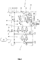
- Fig. 1 shows a trailer brake system 1 for a trailer of a commercial vehicle.
- the trailer brake system 1 has an electronically controlled trailer brake control unit 2.
- the trailer brake control unit 2 is designed as a structural unit 3 and has a housing 4.
- the housing 4 is formed in one or more parts or modular.
- the spring brake and the service brake are formed by a combination brake cylinder.
- the trailer brake control unit 2 has an integrated or flanged control unit 100 in this. This is used to control the solenoid valves used in the trailer brake control unit 2.
- a control unit 100 can be connected via a separate electrical connection or a connection for a bus system with sensors, switches, actuators or other control units of the trailer (or via a suitable interface between the trailer and the towing vehicle) of the towing vehicle and outside of the trailer brake control unit 2 Process signals transmitted via this connection and consider these signals for controlling the solenoid valves.
- the trailer brake control unit 2 has an electronically controlled by the control unit modulator valve device 20 and a spring brake valve device 21.
- the modulator valve means 20 and the other part of the spring brake valve means 21 associated pneumatic components separated by a dashed dividing line 22.
- Such a parting line 22 may exist only for the schematic representation as an imaginary parting line, while in a structural design of the trailer brake control unit 2, the respective pneumatic components of the modulator valve device 20 and the spring brake valve device 21 may be distributed arbitrarily spatially, provided that here illustrated line connections between said pneumatic components are present.
- the modulator valve device 20 preferably has the pneumatic components used in known EBS control units.
- the modulator valve device 20 generates from the voltage applied to the brake control line input port 8 brake control pressure to the service brake line output terminals 16, 18 applied service brake pressure, here for two different circuits.
- the controlled service brake pressure at the service brake line output terminals 16, 18 is proportional to the pressure applied to the brake control line input port 8 or depends thereon according to a predetermined dependency.
- a control or modulation of the operating brake pressure applied to the service brake line output connection 16, 18 takes place in order to reduce slippage of the vehicle wheels assigned to the service brakes and / or to prevent the vehicle wheels from locking.
- the control unit 100 by means of which an electrical control of the modulator valve device 20 and the control of the service brake pressure takes place, preferably the signal of a wheel speed sensor.
- the spring brake valve device 21 serves to provide a spring brake pressure, which is supplied via the spring brake output terminals 14a, 14b, ... the spring-loaded brakes.
- the spring brake valve device 21 in this case has the required pneumatic components such as valves.
- the spring brake valve device 21 may have valves which are formed according to a known from the prior art (for example, the aforementioned prior art) parking valve, release valve and / or emergency brake valve or trailer brake valve.
- the output pressure of the spring brake valve device 21 is fed directly to the spring brakes, for the embodiments shown here, the output pressure of the modulator valve device 20 is connected via a spring-loaded processing device 23 with the spring brakes.
- the spring-memory processing device 23 has an anti-compound valve 24, which is designed as a shuttle valve 25.
- a first input port 26 of the shuttle valve 25 is connected to an output line 27 of the spring brake valve device 21.
- a second input port 28 of the shuttle valve 25 is connected to a service brake line 29.
- the service brake line 29 is acted on by the modulator valve device 20, here for one of the two circuits, controlled service brake pressure corresponding to the pressure at the service brake line output terminals 16.
- An output port 30 of the shuttle valve 25 is connected to the spring brake output ports 14. While such a connection can be made directly, takes place for the illustrated embodiment, this connection via a quick exhaust valve 31, wherein also as shown in the spring-memory processing device 23, a sensor 32 may be integrated, via which the spring brake pressure is detected, which then the control unit 100 of the trailer brake control unit 2 can be supplied.
- the in Fig. 1 dashed delimited spring brake valve device 21 thus on the anti-compound valve 24, the quick exhaust valve 31 and the sensor 32, wherein the spring-loaded processing device 23 as shown, the spring brake output terminals 14 can form.
- the modulator valve device 20 and the spring-loaded brake valve device 21 are connected to one another via the anti-compound valve 24 on the output side. In addition, these are connected via a supply line 33 with each other.
- the supply line 33 is on the one hand (here by the spring-loaded brake valve device 21 with a pressure-locking check valve 34) connected to the supply line inlet port 5 and on the other hand connected to the container port 11. Via the supply line 33, a filling of the container 13 can thus take place via compressed air present at the supply line inlet connection 5.
- the supply line 33 and check valve 34 are not part of the modulator valve device 20 and the spring brake valve device 21 so that they are passed outside the same on the modulator valve device 20 and the spring brake valve device 21, which within the trailer brake control unit 2 or outside of the same can take place. It is also possible that the supply line 6 branches outside the trailer brake control unit 2, in which case the line branches supply the modulator valve device 20 or the spring-loaded brake valve device 21 with compressed air via separate connections of the trailer brake control unit 2 and / or the container 13 with compressed air supply.
- the modulator valve device 20 optionally has a sensor 35, via which the pressure at the brake control line input port 8 is detected, and / or a sensor 36, via which the pressure at the container port 11 is detected.
- the signals of the sensors 35, 36 are supplied to the control unit 100 of the trailer brake control unit 2.
- the pressure applied to the brake control line input port 8 is supplied to a control port 37 of a relay valve 38.
- An input 39 of the relay valve 38 is connected to the Supply line 33 and thus connected via the container port 11 with the container 13 to the compressed air supply.
- Exits 40a, 40b,... Of the relay valve 38 are connected directly to the service brake line output terminals 16 and to the service brake line 29 leading to the anti-compound valve 24.
- the modulator valve device 20 has a solenoid valve 41, which has a supply line 42 of the modulator valve device 20 in a valve position (in Fig. 1 not effective valve position) with the supply line 33 and thus the container port 11 and the container 13 connects and in another valve position (in Fig. 1 effective valve position) with the brake control line input terminal 8 connects.
- the solenoid valve 41 is driven by the electronic control unit 100 of the trailer brake control unit 2.
- the supply line 42 is connected via a solenoid valve device 43 to the control terminal 37 of the relay valve 38. Depending on the electrical control of the solenoid valve device 43, this connects either the supply line 42 to the control port 37 or vent this the control port 37.
- the solenoid valve 43 may, for example, a solenoid valve in training as a 3/2-way valve having in a ventilation position the control terminal 37 with the Supply line 42 connects and shuts off the supply line 42 in a venting position, but the control port 37 vented.
- the solenoid valve device 43 is formed with a solenoid valve 44, which is designed as a check valve and in the in Fig. 1 effective passage position connects the control terminal 37 to the supply line 42 and in the blocking position the control port 37 against the supply line 42 shuts off, and a solenoid valve 45 is formed, which is arranged in a branch line from the connecting line between the solenoid valve 44 and the control terminal 37 and in the in Fig. 1 effective switching position a connection of a vent 46 with the control port 37 shuts off and creates a connection between the vent 46 and control port 37 in the other valve position.
- the supply line 42 branches into supply lines 42a, 42b, which then each have correspondingly designed solenoid valve devices 43a, 43b (here with solenoid valves 44a, 44b, 45a, 45b)
- Control terminals 37a, 37b of the relay valves 38a, 38b are connected, in which case the relay valve 38a is responsible for the modulation of the service brake pressure of a service brake circuit for the service brake line output terminals 16 and the service brake line 29 and the relay valve 38b is responsible for the modulation of the service brake pressure for the other service brake circuit associated service brake line output terminals 18th
- the modulator valve device 20 allows in particular the following modes of operation: For a normal driving operation with existing electric power supply and electronic control of the service brake pressures, the solenoid valve 41 is in the in Fig. 1 switched not effective switching position, so that it supplies the solenoid valve means 43 a, 43 b from the reservoir 13 with compressed air. It can be done by suitable electronic control of the control terminals of the solenoid valve means 43 a, 43 b, the electronic control of the service brake pressures.
- a temporary release of the vehicle wheel to restore the traction in a service brake circuit or both service brake circuits can be done by simultaneously the solenoid valves 44, 45 are switched by electrical energization thereof by the electronic control unit in the in Fig. 1 inactive valve positions. This leads to a venting of the control terminal 37 of the relay valve 38, whereby the controlled service brake pressure is reduced. If then the restoration of traction, so sensed an increase in the speed of the vehicle wheel, again the switching back of the solenoid valves 44, 45 in the in Fig. 1 effective valve positions take place, whereby the control port 37 is again acted upon by the brake control pressure.
- the solenoid valve 41 For a breakdown of the electrical power supply or a defect of the electronic control, the solenoid valve 41 returns due to the application of the spring in the in Fig. 1 effective switching position back and the solenoid valve means 43a, 43b are due to the action of these springs in the in Fig. 1 effective valve positions.
- This has the consequence that the control terminals 37 of the relay valves 38 of the supplied from the towing vehicle via the coupling head brake 10 and the brake control line input terminal. 8 fitting, for example, via the driver by means of the brake pedal predetermined brake control pressure is supplied, which then the relay valve 38 controls operating brake pressures, which are proportional to the brake control pressure.
- an electronic control of the solenoid valves 44, 45 also takes place for a purpose other than avoiding slippage of a blocking of the vehicle wheels.
- a control of a service brake pressure can be brought about by the relay valves, which deviates temporarily and in selected operating situations from the predetermined dependence on the brake control pressure.
- the towing vehicle is braked by engaging a smaller gear and / or a change of train operation in a pushing operation.
- pressurization of the supply line 42 takes place from the container 13, in which case the oscillating or constant pressure level at the control connection 37 can be brought about by the switching over of the magnetic valves 44, 45. If a desired pressure is brought about at the control connection 37 and if this is to be maintained constant, then the two solenoid valves 44, 45 can also be transferred into their blocking position.
- An emergency braking situation can exist for a variety of operating situations and can be identified on the basis of different criteria.
- monitoring of the surroundings of the utility vehicle train via sensors or cameras and corresponding evaluation can be recognized that emergency braking is required.
- an emergency braking situation is present when a demolition of the coupling head stock 7 takes place from the associated coupling head of the towing vehicle or a defect occurs in a supply line 6, since hereby the compressed air supply to the trailer brake system 1 is no longer guaranteed.
- the solenoid valve 41 is made of the in Fig. 1 switched effective valve position in the other valve position, so that the supply line 42 is supplied via the brake control line input port 8 from the container 13 with compressed air.
- a desired, possibly also modulated, service brake force for the two service brake circuits can then be generated.
- the supply line 49 issuing from the supply line input connection 5 branches into supply line branches 51, 52 via a branch 50.
- the supply line branch 51 is part of a vent line branch 53, in which the supply line branch 52 extends via a supply line 52 in the direction of the supply line.
- Input terminal 5 opening check valve 54 is connected to the output line 27.
- the supply line branch 52 is part of a ventilation line branch 55 and in this connected via the check valve 34 with a supply line 56, a check valve 57 and a valve device 58 in this order with the output line 27. From the supply line 56 branches between the check valves 34, 57, the supply line 33, via which the modulator valve device 20 is supplied with compressed air from.
- the check valves 34, 57 allow passage of compressed air from the supply line input port 5 to the output line 27 but block flow in the reverse flow direction.
- the valve device 58 is designed as exclusively pneumatically controlled valve device (here as a ventilation valve 59 or 3/2-way valve) and has a pneumatic control port 60.
- a ventilation valve 59 or 3/2-way valve the valve device 58 assumes a vent position, in which via the valve means 58, the output line 27 is vented, while a shut-off of a port takes place via the check valve 57 via the supply line 56 is supplied with compressed air.
- a pressurization of the control terminal 60 performs the in Fig. 1 non-effective valve position, which is a vent position, forth, in which the supply line 56 is connected via the check valve 57 and the valve means 58 to the output line 27.
- a pneumatic control of the control terminal 60 is carried out for the embodiment according to Fig. 1 via an external, manually operated hand brake valve 61.
- the hand brake valve is supplied via a hand brake valve output port 62 of the trailer brake control unit 2 with compressed air.
- the hand brake pressure output from the manual brake valve 61 as a result of the manual operation is supplied to the trailer brake control unit 2 via a hand brake valve input port 63.
- the hand brake valve output port 62 is in this case connected via a branch line 64 to the supply line 56 between the two check valves 34, 57.
- the hand brake valve input port 63 is connected to the control port 60 via a control line 65.
- the hand brake valve 61 is designed as a ventilation valve 66 or 3/2-way valve.
- a spring takes the hand brake valve 61 without manual operation in Fig. 1 effective venting position in which the manual brake valve 61, the manual brake valve input port 63 and thus the control port 60 vented.
- an operating knob 67 of the hand brake valve 61 this can be transferred to the ventilation position in which the hand brake valve 61 via the hand brake valve output port 62 derived compressed air the hand brake valve inlet port 63 and thus the control port 60 vented.
- a switching of the valve device 58 can be brought about.
- a control surface of the hand brake valve 61 is supplied such that despite the action of the spring, the hand brake valve 61 has a self-holding function such that the hand brake valve once occupied ventilation position (for sufficient pressure at the hand brake valve output port 62) remains in the ventilation position.
- a spring-loaded brake function can be ensured as follows:
- the hand brake valve 61 is in the in Fig. 1 effective venting position, is at the control port 60 of the valve device 58 no control pressure, which this in Fig. 1 effective ventilation position assumes.
- This has the venting of the output line 27 result, which in turn with appropriate loading of the spring brake output terminals 14, the venting of the spring brake and thus the generation of a spring brake force has the consequence.
- the Fig. 1 illustrated operating position of the hand brake valve 61 thus correlates with a parked trailer with a parking brake action, which is brought about by the spring brake. For a release of the parking brake, the manual transfer of the hand brake valve 61 in the in Fig.
- the spring brake valve device 21 ensures as an additional spring brake function an emergency brake function as follows: If it comes to a demolition of the coupling head stock 7 or a defect in the supply line 6, via the open in this vent direction check valve 54, a venting of the output line 27 via the open Coupling head supply 7 or the defect of the supply line 6. The venting of the output line 27 has (without generated by the modulator valve means 20 operating brake pressure) the corresponding venting of the spring brakes result, which then an emergency braking force is generated.
- the driver operates the brake pedal, controls the modulator valve means 20 a service brake pressure, whereby the anti-compound valve 24, the service brake pressure also supplies the spring brakes and corresponding to the amount of service brake pressure in the service brake line 29, a ventilation of the spring brake, so that also at least partially generating the emergency braking force by means of a modulated service brake pressure in the Service brakes can be done.
- the brake control pressure prevailing at the coupling head brake 10 is not supplied via the solenoid valve device 43 to the control port 37 of the relay valve 38. Rather, the voltage applied to the coupling head 10 brake control pressure can be detected by the sensor 35.
- 1 non-effective valve position switched solenoid valve 41 with a compressed air supply to the supply line 42 from the container 13 is then based on electronic control or based on a provided by the tractor (u., Via a bus system and a suitable interface between towing vehicle and trailer) digital Signal or alternatively or in case of redundancy for a defect of the electrical control based on the signal of the sensor 35 by the control unit 100 generating a suitable (possibly modulated or compared to the signal of the pressure sensor 35 depending on the existing operating conditions modified) control pressure with the then the control port 37 is acted upon and on the basis of which the service brake pressure is predetermined.
- the modulator valve means 20 according to the modulator valve means 20 according to Fig. 1 formed and integrated into the trailer brake control unit 2.
- the service brake line 29 connected to the modulator valve device 20 and the output line 27 connected to the spring-loaded brake valve device 21 are also suitable for the following embodiments via the spring-loaded processing device 23 with an anti-compound valve 24 and a quick exhaust valve 31 in a corresponding configuration and integration of the spring memory processing device 23 connected.
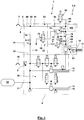
- Fig. 2 is the ventilation line branch 55 accordingly Fig. 1 educated.
- Deviating from Fig. 1 is in the vent line branch 53 between a junction 69 of the vent line branch 53 and the venting line branch 55th arranged with outgoing from the merge 69 output line 27 and the check valve 54, a throttle 70.
- a branch line 71 which is connected to a vent valve 72 or solenoid valve.
- the vent valve 72 has a, preferably without electrical actuation assumed blocking position in which the branch line 51 is shut off, and a preferably occupied with energization venting position, in which the branch line 71 is vented.
- the control terminal 60 is for the embodiment according to Fig. 2 connected via the control line 65 to an output terminal 73 of a shuttle valve 74.
- An input port 75 is connected via a solenoid valve 76 at a location between the check valves 34, 57 with the venting line branch 55, here the supply line 56.
- the solenoid valve 76 is designed here as a 3/2-way valve and takes without electrical energization according to the valve position Fig. 2 in which the input port 75 is vented, and with energization the other valve position occupies, in which the input port 75 is connected to the supply line 56.
- the other input terminal 77 is connected via a two-line 78 to the line section 79 of the vent line branch 53, which is arranged between the throttle 70 and the check valve 54.
- the spring brake valve device 21 allows the following spring-loaded brake functions: If the parked trailer coupled via the coupling head stock 7 with a towing vehicle and the vent valve 72 is in the locked position and the solenoid valve 76 in the vent position, the spring brakes are vented through the valve means 58, so that a parking brake effect is brought about.
- the parking brake for example, based on a manual induction of an electrical release signal via a switch by the driver or automatically with the detection of the operation of the ignition key or the engagement of a gear or with the operation of the accelerator pedal, be solved in which the solenoid valve 76th is electrically switched to the ventilation position.
- the spring-loaded brake valve device 21 also ensures an emergency brake function such that in the case of a demolition of the coupling head stock 7 or a defect in the supply line 6, a venting of the line section 79 takes place, which takes place relatively quickly due to the small line volume.
- a venting of the spring brake via the coupling head stock 7 or the defect of the supply line 6 due to the effect of the throttle 70 is not or only very slowly.
- the venting of the line section 79 has the consequence that also the input port 77 of the shuttle valve 74 is vented very quickly.
- control connection 60 initially remains pressurized so that the valve device 58 retains the ventilation position and pressurized air from the reservoir 13 via the supply line 33, the supply line 56, the check valve 57 and the valve means 58, the output line 27 and thus the spring-loaded brakes applied.
- vent valve 72 If this is controlled by turning off the trailer in the venting position with simultaneous switching of the solenoid valve 76 in the venting position, the venting of the control port 60, the switching of the valve device 58 in the venting position and thus the venting of the spring brake with the generation of the parking brake effect. Are vented in this way, the spring brake and the line section 79, the energization of the vent valve 72 can be removed again and this be transferred to the locked position, without this has a renewed ventilation of the spring brake result.
- Fig. 4 For the embodiment according to Fig. 4 is (otherwise Fig. 2 corresponding embodiment) instead of arranged in the trailer brake control unit branch line 71 with vent valve 72 a branched off from the line section 79 branch line 80 via a hand brake valve port 81 with a manual brake valve 82.
- the hand brake valve 82 is manually operable here and has a blocking position and a venting position.
- the control port 60 of the valve device 58 can be vented, so that this the venting position occupies and to generate a parking brake effect via the valve device 58, the spring-loaded brakes are vented.
- the valve device 58 remains in the venting position regardless of which position the manual brake valve 82 occupies.
- the electrical switching of the solenoid valve 76 is required for this purpose, which can be made dependent on a suitable authentication of the user, with which a spring brake immobilization function can be provided.
- Fig. 5 illustrated embodiment corresponds to the ventilation line branch 55 with the supply line branch 52, the check valve 34, the check valve 57 and the valve device 58 and with respect to the integration in the trailer control unit 2 the previous embodiments.
- the vent line branch 53 is not connected directly to the merge 69 with the output line 27. Rather, that is Ventilation line branch 55 connected to the supply line branch 51 via the check valve 54 to the input terminal 77 of the shuttle valve 74, the other input terminal 75 according to the embodiment of FIG Fig. 2 is connected via the solenoid valve 76 to the supply line 56.
- the output port 73 of the shuttle valve 74 is connected to the control port 60 of the valve device 58.
- a solenoid valve 83 is arranged, which without energization in Fig. 5 occupies effective ventilation position, while this with electric current supply in Fig. 5 not effective ventilation position assumes.
- the pressure in the output line 27 depends exclusively on the valve position of the valve device 58.
- the check valve 54 can be bypassed via a bypass line 84.
- the bypass line 84 may be formed separately from the check valve 54 and in this may be arranged a pneumatically controlled or electrically controlled valve, which may have an open position for activating the bypass line 84 and a closed position for shutting off the bypass line 84.
- bypass line 84 and the check valve 54 are integrated into a pneumatically controlled valve 85, which in the in Fig. 5 effective operating position brings the check valve 54 to the effect, while this brings in the other valve position, the bypass line 84 to action.
- the valve 85 has a control port 86.
- the control port 86 is connected via a branch line 87 to the output line 27.
- a sensor 88 is present, which senses the pressure in the supply line 49 or at the supply line input terminal 5.
- a parking brake effect can be brought about, for example caused by the manual operation of an electric switch, which then the switching of the solenoid valve 83 in the Venting causes or by elimination of the electrical power supply.
- a parking function can be ensured.
- the trailer If the trailer is uncoupled from the traction vehicle, it can be ensured by switching the solenoid valve 76 into the ventilation position that pressure is applied to the output port 73.
- a braking effect can be brought about via the spring-loaded brakes or not, so that a release function is ensured.
- the solenoid valve 83 is in the venting position and are activated in this way, the spring brakes, the switching of the solenoid valve 83 in the ventilation position, which is required for the elimination of the braking effect of the spring brakes, be made dependent on an authentication by the user, with a Spring brake immobilization function can be guaranteed.
- the electrical energization of the solenoid valve 76 can be eliminated, since then despite the venting of the input terminal 75 due to the ventilation of the input port 77 via the valve 85 from the coupling head stock 7, the output port 73 is pressurized, whereby the ventilation position of the valve device 58 is maintained. If it then comes to an emergency braking situation, the ventilation of the control port 60 via the valve 85. This vent then leads to the activation of the spring brakes to bring about an emergency braking force. Due to the venting of the output line 27, the valve 85 automatically returns to the valve position according to Fig. 5 with effective check valve 54 back.
- Fig. 6 shows a basically Fig. 5 corresponding embodiment.
- the control port 86 of the valve 85 is not directly connected to the branch line 87. Rather, here the control port 86 is connected to an output port 89 of a shuttle valve 90.
- An input port 91 of the shuttle valve 90 is connected to the branch line 87, while the other input port 92 of the shuttle valve 90 is pressurized via a branch line 93 with the pressure at the brake control line input port 8.
- the spring brake released, by means of the generation of a brake control pressure to the brake control line input terminal 8, for example by actuation of a brake pedal, a switching of the valve 85 with activation of the bypass line 84 take place.
- Fig. 7 shows an embodiment in which on the one hand the bringing about of a spring brake effect by means of a hand brake valve 61 is possible, as this for Fig. 1 has been described with appropriate design and connection of the hand brake valve 61 with the trailer brake control unit 2.
- the design of the vent line branch 53 and the ventilation line branch 55 corresponds basically to the in Fig. 1 illustrated embodiment.
- the supply line 63 is passed to the check valve 34 through a pneumatically controlled valve 94, wherein the supply line 56 is effective with the check valve 34 in all valve positions of the valve 94 unchanged.
- the valve 94 has a port 95 which is connected (via the branch 50 and the supply line 49) to the supply line input port 5.
- a port 96 of the valve 94 is connected to the brake control line input port 8.
- a port 97 of valve 94 is connected to the venting conduit branch. Finally, a port 98 is connected to the modulator valve means 20.
- the valve 94 has a pneumatic control port 99 connected to the supply line branch 51 is. Without acting on the control terminal 99 of the valve 94, the valve 94 takes the in Fig. 7 effective switching position, in which this connects the terminal 95 via the check valve 34 with both the terminal 97 and the terminal 98, while the terminal 96 is shut off. For a central valve position with a central pressure applied to the control port 99, the valve 94 connects the port 95 via the check valve 34 to the port 97, while the ports 96 and 98 are shut off. On the other hand, in the third valve position for the highest pressure range applied to the control port 99, the valve 94 connects the port 95 to the port 97 via the check valve 34, while the ports 96, 98 are directly connected to each other.
- the valve 94 is a valve which, in a corresponding embodiment, is also distributed for other purposes under the TEM, TrCM, TrCM + (with the "Safe Parking” function).
- the valve 94 is preferably a 4/3-way valve.
Landscapes
- Engineering & Computer Science (AREA)
- Transportation (AREA)
- Mechanical Engineering (AREA)
- Regulating Braking Force (AREA)
- Valves And Accessory Devices For Braking Systems (AREA)
- Braking Systems And Boosters (AREA)
Priority Applications (1)
| Application Number | Priority Date | Filing Date | Title |
|---|---|---|---|
| PL18186400T PL3444155T3 (pl) | 2017-08-14 | 2018-07-30 | Elektronicznie sterowana jednostka sterująca hamulcem przyczepy oraz układ hamulcowy przyczepy |
Applications Claiming Priority (1)
| Application Number | Priority Date | Filing Date | Title |
|---|---|---|---|
| DE102017118529.1A DE102017118529B4 (de) | 2017-08-14 | 2017-08-14 | Elektronisch gesteuerte Anhänger-Bremssteuereinheit und Anhänger-Bremsanlage |
Publications (2)
| Publication Number | Publication Date |
|---|---|
| EP3444155A1 true EP3444155A1 (fr) | 2019-02-20 |
| EP3444155B1 EP3444155B1 (fr) | 2020-08-05 |
Family
ID=63144816
Family Applications (1)
| Application Number | Title | Priority Date | Filing Date |
|---|---|---|---|
| EP18186400.0A Active EP3444155B1 (fr) | 2017-08-14 | 2018-07-30 | Unité de commande de frein de remorque à commande électronique et système de freinage de remorque |
Country Status (5)
| Country | Link |
|---|---|
| EP (1) | EP3444155B1 (fr) |
| CN (1) | CN109383478B (fr) |
| DE (1) | DE102017118529B4 (fr) |
| HU (1) | HUE051223T2 (fr) |
| PL (1) | PL3444155T3 (fr) |
Cited By (10)
| Publication number | Priority date | Publication date | Assignee | Title |
|---|---|---|---|---|
| WO2020225167A1 (fr) * | 2019-05-03 | 2020-11-12 | Knorr-Bremse Systeme Fur Nutzfahrzeuge Gmbh | Système de freinage de remorque |
| CN113479175A (zh) * | 2021-08-23 | 2021-10-08 | 广州朗晴电动车有限公司 | 一种可自行式消防挂车的制动系统装置 |
| CN113905937A (zh) * | 2019-06-06 | 2022-01-07 | 卡特彼勒公司 | 用于紧急停止的自动制动施加 |
| WO2023138926A1 (fr) * | 2022-01-19 | 2023-07-27 | Zf Cv Systems Global Gmbh | Système de frein de stationnement de remorque électropneumatique, remorque, combinaison de remorquage |
| CN116749932A (zh) * | 2023-05-31 | 2023-09-15 | 国能神东煤炭集团有限责任公司 | 集成式液压控制阀组及具有其的车辆 |
| WO2024023329A1 (fr) * | 2022-07-29 | 2024-02-01 | Haldex Brake Products Ab | Système de freinage de remorque |
| CN117545670A (zh) * | 2021-07-21 | 2024-02-09 | 采埃孚商用车系统全球有限公司 | 具有紧急释放部的电动气动驻车制动单元 |
| CN117601824A (zh) * | 2023-11-30 | 2024-02-27 | 浙江万安科技股份有限公司 | Ebs后桥控制模块总成 |
| EP4574593A1 (fr) * | 2023-12-20 | 2025-06-25 | KAMAG Transporttechnik GmbH & Co. KG | Véhicule de transport et procédé pour effectuer une manoeuvre de freinage |
| WO2026062084A1 (fr) * | 2024-09-17 | 2026-03-26 | Knorr-Bremse Systeme für Nutzfahrzeuge GmbH | Système de freinage de remorque |
Families Citing this family (16)
| Publication number | Priority date | Publication date | Assignee | Title |
|---|---|---|---|---|
| CN106627547B (zh) * | 2016-11-17 | 2019-01-29 | 广州汽车集团股份有限公司 | 兼容自动驻车功能的电子驻车制动系统、起步方法及车辆 |
| DE102019106274A1 (de) * | 2019-03-12 | 2020-09-17 | Wabco Gmbh | Elektronisch steuerbares Bremssystem mit zwei Rückfallebenen (alternative Ausführung) |
| GB2583723B (en) | 2019-05-03 | 2023-07-05 | Knorr Bremse Systeme Fuer Nutzfahrzeuge Gmbh | Trailer braking system |
| DE102019127727A1 (de) * | 2019-10-15 | 2021-04-15 | Knorr-Bremse Systeme für Nutzfahrzeuge GmbH | Vorrichtung und Verfahren zum Steuern einer Bremsanlage eines Anhängers eines Fahrzeuggespanns von einem Zugfahrzeug des Fahrzeuggespanns aus, Steuersystem zum Steuern einer Bremsanlage eines Fahrzeuggespanns und Zugfahrzeug für einen Anhänger |
| DE102019130762A1 (de) * | 2019-11-14 | 2021-05-20 | Wabco Europe Bvba | Elektropneumatisches Steuermodul |
| EP3967561B1 (fr) * | 2020-09-11 | 2024-10-30 | Haldex Aktiebolag | Équipement d'air comprimé de remorque de véhicule utilitaire |
| EP3967562B1 (fr) | 2020-09-11 | 2023-12-13 | Haldex Brake Products Aktiebolag | Équipement à air comprimé pour une remorque |
| DE102020124225A1 (de) | 2020-09-17 | 2022-03-17 | Zf Cv Systems Europe Bv | Ventilanordnung eines Zugfahrzeugs zur Steuerung einer pneumatischen Bremsanlage eines Anhängerfahrzeugs und Verfahren zu deren Steuerung |
| EP4228941B1 (fr) * | 2020-10-14 | 2025-02-26 | ZF CV Systems Europe BV | Modulateur de pression de freinage et utilisation d'un modulateur de pression de freinage |
| DE102020130276A1 (de) * | 2020-11-17 | 2022-05-19 | Zf Cv Systems Global Gmbh | Ausfallsicherheitsventileinheit, elektronisch steuerbares pneumatisches Bremssystem, Fahrzeug, Verfahren |
| JP7327364B2 (ja) * | 2020-11-27 | 2023-08-16 | トヨタ自動車株式会社 | ブレーキシステム |
| DE102020132722A1 (de) | 2020-12-09 | 2022-06-09 | Zf Cv Systems Europe Bv | Druckluftbremsanlage eines Zugfahrzeugs |
| DE102021117212A1 (de) | 2021-07-05 | 2023-01-05 | Zf Cv Systems Global Gmbh | Auswahl eines Anhängers für einen Transport |
| DE102022100288A1 (de) | 2022-01-07 | 2023-07-13 | Zf Cv Systems Europe Bv | Verfahren zum Auslösen eines RtR-Ventils, Steuergerät, Luftfedersystem und Anhängefahrzeug |
| DE102022204480A1 (de) | 2022-05-06 | 2023-11-09 | Zf Friedrichshafen Ag | Betätigungssystem für eine Fahrzeugbremse |
| DE102022114280A1 (de) | 2022-06-07 | 2023-12-07 | Zf Cv Systems Global Gmbh | Verfahren und Vorrichtung zum sicheren Bremsen eines Anhängers |
Citations (2)
| Publication number | Priority date | Publication date | Assignee | Title |
|---|---|---|---|---|
| GB2540346A (en) * | 2015-07-08 | 2017-01-18 | Haldex Brake Products Ltd | Vehicle braking system |
| WO2018007799A1 (fr) * | 2016-07-05 | 2018-01-11 | Haldex Brake Products Ab | Système de freinage de véhicule |
Family Cites Families (16)
| Publication number | Priority date | Publication date | Assignee | Title |
|---|---|---|---|---|
| DE3522183C1 (en) | 1985-06-21 | 1989-08-31 | Graubremse Gmbh | Brake system for vehicles with spring loaded brake cylinders |
| EP1188634B2 (fr) | 2000-09-14 | 2011-12-21 | WABCO GmbH | Soupape de frein de remorque pour remorques à commande de freinage électronique et à sécurité améliorée de remorque stationnée |
| DE10139757A1 (de) * | 2000-09-14 | 2002-05-29 | Wabco Gmbh & Co Ohg | Anhängerbremsventil für Anhängefahrzeuge mit elektronischer Bremsregelung und erweiterter Sicherheit des geparkten Anhängers |
| DE102005019479B3 (de) | 2005-04-27 | 2007-01-18 | Haldex Brake Products Gmbh | Anhängerbremsventil für einen Kraftfahrzeug-Anhänger |
| DE102006036748A1 (de) * | 2006-08-05 | 2008-02-07 | Wabco Gmbh | Elektrisch gesteuerte Bremsanlage |
| DE102007047691A1 (de) * | 2007-10-05 | 2009-04-09 | Wabco Gmbh | Elektropneumatischer Feststellbremsmodulator zur Steuerung einer Feststellbremsfunktion von Bremsen eines Anhängefahrzeugs in einem Fahrzeugzug |
| DE102007053765B4 (de) | 2007-11-12 | 2013-03-21 | Haldex Brake Products Gmbh | Manuell betätigbares Ventil für eine Bremsanlage eines Anhängers |
| DE102007053764B4 (de) | 2007-11-12 | 2009-08-20 | Haldex Brake Products Gmbh | Bremsanlage für einen Anhänger eines Kraftfahrzeuges |
| DE102009031785A1 (de) | 2009-07-06 | 2011-01-13 | Wabco Gmbh | Pneumatische Bremsanlage für ein Anhängefahrzeug und Bremssteuermodulator |
| GB2492124B (en) | 2011-06-22 | 2017-08-09 | Haldex Brake Prod Ab | Vehicle braking system |
| DE102011053529B4 (de) | 2011-09-12 | 2014-06-26 | Haldex Brake Products Gmbh | Ventilbaugruppe für eine Anhängerbremsanlage |
| DE102012101871B4 (de) | 2012-03-06 | 2013-12-12 | Haldex Brake Products Gmbh | Parkbremsventileinrichtung und pneumatische Anhänger-Druckluftbremsanlage |
| DE102013100538B4 (de) | 2013-01-18 | 2016-06-02 | Haldex Brake Products Gmbh | Druckluftanlage eines Anhängers eines Nutzfahrzeugs |
| DE102013100537A1 (de) | 2013-01-18 | 2014-07-24 | Haldex Brake Products Gmbh | Ventileinrichtung für eine Druckluftanlage eines Anhängers eines Nutzfahrzeugs |
| DE102013106875B4 (de) | 2013-07-01 | 2019-01-31 | Haldex Brake Products Aktiebolag | EPI-Modul |
| DE102015116317B4 (de) * | 2015-09-28 | 2021-10-21 | Knorr-Bremse Systeme für Nutzfahrzeuge GmbH | Elektro-pneumatische Parkbremseinrichtung eines Fahrzeugs mit weiterem Steuerkreis und Zugfahrzeug mit elektro-pneumatischer Parkbremseinrichtung |
-
2017
- 2017-08-14 DE DE102017118529.1A patent/DE102017118529B4/de active Active
-
2018
- 2018-07-30 EP EP18186400.0A patent/EP3444155B1/fr active Active
- 2018-07-30 HU HUE18186400A patent/HUE051223T2/hu unknown
- 2018-07-30 PL PL18186400T patent/PL3444155T3/pl unknown
- 2018-08-14 CN CN201810922743.2A patent/CN109383478B/zh active Active
Patent Citations (2)
| Publication number | Priority date | Publication date | Assignee | Title |
|---|---|---|---|---|
| GB2540346A (en) * | 2015-07-08 | 2017-01-18 | Haldex Brake Products Ltd | Vehicle braking system |
| WO2018007799A1 (fr) * | 2016-07-05 | 2018-01-11 | Haldex Brake Products Ab | Système de freinage de véhicule |
Cited By (11)
| Publication number | Priority date | Publication date | Assignee | Title |
|---|---|---|---|---|
| WO2020225167A1 (fr) * | 2019-05-03 | 2020-11-12 | Knorr-Bremse Systeme Fur Nutzfahrzeuge Gmbh | Système de freinage de remorque |
| US12049205B2 (en) | 2019-05-03 | 2024-07-30 | Knorr-Bremse Systeme Fuer Nutzfahrzeuge Gmbh | Trailer braking system |
| CN113905937A (zh) * | 2019-06-06 | 2022-01-07 | 卡特彼勒公司 | 用于紧急停止的自动制动施加 |
| CN117545670A (zh) * | 2021-07-21 | 2024-02-09 | 采埃孚商用车系统全球有限公司 | 具有紧急释放部的电动气动驻车制动单元 |
| CN113479175A (zh) * | 2021-08-23 | 2021-10-08 | 广州朗晴电动车有限公司 | 一种可自行式消防挂车的制动系统装置 |
| WO2023138926A1 (fr) * | 2022-01-19 | 2023-07-27 | Zf Cv Systems Global Gmbh | Système de frein de stationnement de remorque électropneumatique, remorque, combinaison de remorquage |
| WO2024023329A1 (fr) * | 2022-07-29 | 2024-02-01 | Haldex Brake Products Ab | Système de freinage de remorque |
| CN116749932A (zh) * | 2023-05-31 | 2023-09-15 | 国能神东煤炭集团有限责任公司 | 集成式液压控制阀组及具有其的车辆 |
| CN117601824A (zh) * | 2023-11-30 | 2024-02-27 | 浙江万安科技股份有限公司 | Ebs后桥控制模块总成 |
| EP4574593A1 (fr) * | 2023-12-20 | 2025-06-25 | KAMAG Transporttechnik GmbH & Co. KG | Véhicule de transport et procédé pour effectuer une manoeuvre de freinage |
| WO2026062084A1 (fr) * | 2024-09-17 | 2026-03-26 | Knorr-Bremse Systeme für Nutzfahrzeuge GmbH | Système de freinage de remorque |
Also Published As
| Publication number | Publication date |
|---|---|
| DE102017118529B4 (de) | 2019-05-29 |
| DE102017118529A1 (de) | 2019-02-14 |
| CN109383478A (zh) | 2019-02-26 |
| PL3444155T3 (pl) | 2020-12-28 |
| CN109383478B (zh) | 2022-03-01 |
| HUE051223T2 (hu) | 2021-03-01 |
| EP3444155B1 (fr) | 2020-08-05 |
Similar Documents
| Publication | Publication Date | Title |
|---|---|---|
| DE102017118529B4 (de) | Elektronisch gesteuerte Anhänger-Bremssteuereinheit und Anhänger-Bremsanlage | |
| EP2121397B1 (fr) | Module frein de stationnement pour dispositif de freinage actionné par fluide sous pression | |
| EP3145769B1 (fr) | Moyen de commande de freinage électropneumatique avec purge automatique du frein à accumulation en cas de panne de courant | |
| EP3356192B1 (fr) | Frein de stationnement électropneumatique d'un vehicule avec autre système de contrôle | |
| EP1504975B1 (fr) | Système de freinage pour un véhicule utilisant un moyen de pression | |
| EP1502778B2 (fr) | Système de traitement de l'air comprimé pour véhicules | |
| EP3749558B1 (fr) | Système de freinage pour un véhicule utilitaire, unité de mise à disposition d'air comprimé et utilisation d'une unité de mise à disposition d'air comprimé | |
| EP2754594B1 (fr) | Procédé et dispositif de commande d'une installation de freinage à air comprimé d'un train de véhicule automobile | |
| EP2939892B1 (fr) | Frein de stationnement électrique pour un véhicule | |
| EP2650183B1 (fr) | Dispositif de soupape de frein de stationnement et installation de freinage à air comprimé pneumatique pour remorque | |
| EP3967561B1 (fr) | Équipement d'air comprimé de remorque de véhicule utilitaire | |
| EP3515770B1 (fr) | Arrangement de vannes de frein de stationnement pour commander un frein d'immobilisation à ressort accumulateur | |
| DE102017006356A1 (de) | Elektro-Pneumatische Handbremse (EPH) mit integriertem TCV (Europäische Ansteuerung) | |
| DE102017005979A1 (de) | Elektro-Pneumatische Handbremse (EPH) mit integrierten TCV (skandinavische Ansteuerung | |
| DE102013106260B4 (de) | Elektropneumatische Bremsanlage | |
| EP0883538A1 (fr) | Valve de commande de remorque pour systeme de freinage a air comprime de vehicule a moteur | |
| WO2015154787A1 (fr) | Dispositif de commande électropneumatique de frein de stationnement | |
| EP2939891B1 (fr) | Frein de stationnement électrique | |
| EP2570316B1 (fr) | Dispositif de préparation d'air comprimé pour un véhicule utilitaire | |
| EP0547407B1 (fr) | Système de freinage à air comprimé, en particulier pour véhicules commerciales | |
| DE102011053707A1 (de) | Druckluftaufbereitungseinheit | |
| EP4466167A1 (fr) | Ensemble valve de frein de stationnement fiable sur le plan fonctionnel présentant une commutation multivoies en série | |
| EP3967562B1 (fr) | Équipement à air comprimé pour une remorque | |
| EP2368778B1 (fr) | Système de commande de freinage d'une machine de travail mobile, notamment chariot élévateur | |
| EP4259498A1 (fr) | Système de freinage à air comprimé pour véhicule tracteur |
Legal Events
| Date | Code | Title | Description |
|---|---|---|---|
| PUAI | Public reference made under article 153(3) epc to a published international application that has entered the european phase |
Free format text: ORIGINAL CODE: 0009012 |
|
| STAA | Information on the status of an ep patent application or granted ep patent |
Free format text: STATUS: REQUEST FOR EXAMINATION WAS MADE |
|
| 17P | Request for examination filed |
Effective date: 20181126 |
|
| AK | Designated contracting states |
Kind code of ref document: A1 Designated state(s): AL AT BE BG CH CY CZ DE DK EE ES FI FR GB GR HR HU IE IS IT LI LT LU LV MC MK MT NL NO PL PT RO RS SE SI SK SM TR |
|
| AX | Request for extension of the european patent |
Extension state: BA ME |
|
| GRAP | Despatch of communication of intention to grant a patent |
Free format text: ORIGINAL CODE: EPIDOSNIGR1 |
|
| STAA | Information on the status of an ep patent application or granted ep patent |
Free format text: STATUS: GRANT OF PATENT IS INTENDED |
|
| INTG | Intention to grant announced |
Effective date: 20200210 |
|
| GRAS | Grant fee paid |
Free format text: ORIGINAL CODE: EPIDOSNIGR3 |
|
| GRAA | (expected) grant |
Free format text: ORIGINAL CODE: 0009210 |
|
| STAA | Information on the status of an ep patent application or granted ep patent |
Free format text: STATUS: THE PATENT HAS BEEN GRANTED |
|
| AK | Designated contracting states |
Kind code of ref document: B1 Designated state(s): AL AT BE BG CH CY CZ DE DK EE ES FI FR GB GR HR HU IE IS IT LI LT LU LV MC MK MT NL NO PL PT RO RS SE SI SK SM TR |
|
| REG | Reference to a national code |
Ref country code: GB Ref legal event code: FG4D Free format text: NOT ENGLISH |
|
| REG | Reference to a national code |
Ref country code: CH Ref legal event code: EP |
|
| REG | Reference to a national code |
Ref country code: AT Ref legal event code: REF Ref document number: 1298309 Country of ref document: AT Kind code of ref document: T Effective date: 20200815 |
|
| REG | Reference to a national code |
Ref country code: DE Ref legal event code: R096 Ref document number: 502018002098 Country of ref document: DE |
|
| REG | Reference to a national code |
Ref country code: IE Ref legal event code: FG4D Free format text: LANGUAGE OF EP DOCUMENT: GERMAN |
|
| REG | Reference to a national code |
Ref country code: LT Ref legal event code: MG4D |
|
| REG | Reference to a national code |
Ref country code: NL Ref legal event code: MP Effective date: 20200805 |
|
| PG25 | Lapsed in a contracting state [announced via postgrant information from national office to epo] |
Ref country code: LT Free format text: LAPSE BECAUSE OF FAILURE TO SUBMIT A TRANSLATION OF THE DESCRIPTION OR TO PAY THE FEE WITHIN THE PRESCRIBED TIME-LIMIT Effective date: 20200805 Ref country code: HR Free format text: LAPSE BECAUSE OF FAILURE TO SUBMIT A TRANSLATION OF THE DESCRIPTION OR TO PAY THE FEE WITHIN THE PRESCRIBED TIME-LIMIT Effective date: 20200805 Ref country code: NO Free format text: LAPSE BECAUSE OF FAILURE TO SUBMIT A TRANSLATION OF THE DESCRIPTION OR TO PAY THE FEE WITHIN THE PRESCRIBED TIME-LIMIT Effective date: 20201105 Ref country code: ES Free format text: LAPSE BECAUSE OF FAILURE TO SUBMIT A TRANSLATION OF THE DESCRIPTION OR TO PAY THE FEE WITHIN THE PRESCRIBED TIME-LIMIT Effective date: 20200805 Ref country code: BG Free format text: LAPSE BECAUSE OF FAILURE TO SUBMIT A TRANSLATION OF THE DESCRIPTION OR TO PAY THE FEE WITHIN THE PRESCRIBED TIME-LIMIT Effective date: 20201105 Ref country code: PT Free format text: LAPSE BECAUSE OF FAILURE TO SUBMIT A TRANSLATION OF THE DESCRIPTION OR TO PAY THE FEE WITHIN THE PRESCRIBED TIME-LIMIT Effective date: 20201207 Ref country code: GR Free format text: LAPSE BECAUSE OF FAILURE TO SUBMIT A TRANSLATION OF THE DESCRIPTION OR TO PAY THE FEE WITHIN THE PRESCRIBED TIME-LIMIT Effective date: 20201106 Ref country code: FI Free format text: LAPSE BECAUSE OF FAILURE TO SUBMIT A TRANSLATION OF THE DESCRIPTION OR TO PAY THE FEE WITHIN THE PRESCRIBED TIME-LIMIT Effective date: 20200805 Ref country code: SE Free format text: LAPSE BECAUSE OF FAILURE TO SUBMIT A TRANSLATION OF THE DESCRIPTION OR TO PAY THE FEE WITHIN THE PRESCRIBED TIME-LIMIT Effective date: 20200805 |
|
| PG25 | Lapsed in a contracting state [announced via postgrant information from national office to epo] |
Ref country code: RS Free format text: LAPSE BECAUSE OF FAILURE TO SUBMIT A TRANSLATION OF THE DESCRIPTION OR TO PAY THE FEE WITHIN THE PRESCRIBED TIME-LIMIT Effective date: 20200805 Ref country code: LV Free format text: LAPSE BECAUSE OF FAILURE TO SUBMIT A TRANSLATION OF THE DESCRIPTION OR TO PAY THE FEE WITHIN THE PRESCRIBED TIME-LIMIT Effective date: 20200805 Ref country code: NL Free format text: LAPSE BECAUSE OF FAILURE TO SUBMIT A TRANSLATION OF THE DESCRIPTION OR TO PAY THE FEE WITHIN THE PRESCRIBED TIME-LIMIT Effective date: 20200805 Ref country code: IS Free format text: LAPSE BECAUSE OF FAILURE TO SUBMIT A TRANSLATION OF THE DESCRIPTION OR TO PAY THE FEE WITHIN THE PRESCRIBED TIME-LIMIT Effective date: 20201205 |
|
| REG | Reference to a national code |
Ref country code: HU Ref legal event code: AG4A Ref document number: E051223 Country of ref document: HU |
|
| PG25 | Lapsed in a contracting state [announced via postgrant information from national office to epo] |
Ref country code: SM Free format text: LAPSE BECAUSE OF FAILURE TO SUBMIT A TRANSLATION OF THE DESCRIPTION OR TO PAY THE FEE WITHIN THE PRESCRIBED TIME-LIMIT Effective date: 20200805 Ref country code: RO Free format text: LAPSE BECAUSE OF FAILURE TO SUBMIT A TRANSLATION OF THE DESCRIPTION OR TO PAY THE FEE WITHIN THE PRESCRIBED TIME-LIMIT Effective date: 20200805 Ref country code: CZ Free format text: LAPSE BECAUSE OF FAILURE TO SUBMIT A TRANSLATION OF THE DESCRIPTION OR TO PAY THE FEE WITHIN THE PRESCRIBED TIME-LIMIT Effective date: 20200805 Ref country code: DK Free format text: LAPSE BECAUSE OF FAILURE TO SUBMIT A TRANSLATION OF THE DESCRIPTION OR TO PAY THE FEE WITHIN THE PRESCRIBED TIME-LIMIT Effective date: 20200805 Ref country code: EE Free format text: LAPSE BECAUSE OF FAILURE TO SUBMIT A TRANSLATION OF THE DESCRIPTION OR TO PAY THE FEE WITHIN THE PRESCRIBED TIME-LIMIT Effective date: 20200805 |
|
| REG | Reference to a national code |
Ref country code: DE Ref legal event code: R097 Ref document number: 502018002098 Country of ref document: DE |
|
| PG25 | Lapsed in a contracting state [announced via postgrant information from national office to epo] |
Ref country code: AL Free format text: LAPSE BECAUSE OF FAILURE TO SUBMIT A TRANSLATION OF THE DESCRIPTION OR TO PAY THE FEE WITHIN THE PRESCRIBED TIME-LIMIT Effective date: 20200805 |
|
| PLBE | No opposition filed within time limit |
Free format text: ORIGINAL CODE: 0009261 |
|
| STAA | Information on the status of an ep patent application or granted ep patent |
Free format text: STATUS: NO OPPOSITION FILED WITHIN TIME LIMIT |
|
| PG25 | Lapsed in a contracting state [announced via postgrant information from national office to epo] |
Ref country code: SK Free format text: LAPSE BECAUSE OF FAILURE TO SUBMIT A TRANSLATION OF THE DESCRIPTION OR TO PAY THE FEE WITHIN THE PRESCRIBED TIME-LIMIT Effective date: 20200805 |
|
| 26N | No opposition filed |
Effective date: 20210507 |
|
| PG25 | Lapsed in a contracting state [announced via postgrant information from national office to epo] |
Ref country code: IT Free format text: LAPSE BECAUSE OF FAILURE TO SUBMIT A TRANSLATION OF THE DESCRIPTION OR TO PAY THE FEE WITHIN THE PRESCRIBED TIME-LIMIT Effective date: 20200805 |
|
| PG25 | Lapsed in a contracting state [announced via postgrant information from national office to epo] |
Ref country code: SI Free format text: LAPSE BECAUSE OF FAILURE TO SUBMIT A TRANSLATION OF THE DESCRIPTION OR TO PAY THE FEE WITHIN THE PRESCRIBED TIME-LIMIT Effective date: 20200805 |
|
| REG | Reference to a national code |
Ref country code: CH Ref legal event code: PL |
|
| PG25 | Lapsed in a contracting state [announced via postgrant information from national office to epo] |
Ref country code: MC Free format text: LAPSE BECAUSE OF FAILURE TO SUBMIT A TRANSLATION OF THE DESCRIPTION OR TO PAY THE FEE WITHIN THE PRESCRIBED TIME-LIMIT Effective date: 20200805 |
|
| REG | Reference to a national code |
Ref country code: BE Ref legal event code: MM Effective date: 20210731 |
|
| PG25 | Lapsed in a contracting state [announced via postgrant information from national office to epo] |
Ref country code: LI Free format text: LAPSE BECAUSE OF NON-PAYMENT OF DUE FEES Effective date: 20210731 Ref country code: CH Free format text: LAPSE BECAUSE OF NON-PAYMENT OF DUE FEES Effective date: 20210731 |
|
| PG25 | Lapsed in a contracting state [announced via postgrant information from national office to epo] |
Ref country code: LU Free format text: LAPSE BECAUSE OF NON-PAYMENT OF DUE FEES Effective date: 20210730 |
|
| PG25 | Lapsed in a contracting state [announced via postgrant information from national office to epo] |
Ref country code: IE Free format text: LAPSE BECAUSE OF NON-PAYMENT OF DUE FEES Effective date: 20210730 Ref country code: BE Free format text: LAPSE BECAUSE OF NON-PAYMENT OF DUE FEES Effective date: 20210731 |
|
| PG25 | Lapsed in a contracting state [announced via postgrant information from national office to epo] |
Ref country code: CY Free format text: LAPSE BECAUSE OF FAILURE TO SUBMIT A TRANSLATION OF THE DESCRIPTION OR TO PAY THE FEE WITHIN THE PRESCRIBED TIME-LIMIT Effective date: 20200805 |
|
| P01 | Opt-out of the competence of the unified patent court (upc) registered |
Effective date: 20230529 |
|
| REG | Reference to a national code |
Ref country code: DE Ref legal event code: R082 Ref document number: 502018002098 Country of ref document: DE Representative=s name: MUELLER SCHUPFNER & PARTNER PATENT- UND RECHTS, DE |
|
| PG25 | Lapsed in a contracting state [announced via postgrant information from national office to epo] |
Ref country code: MK Free format text: LAPSE BECAUSE OF FAILURE TO SUBMIT A TRANSLATION OF THE DESCRIPTION OR TO PAY THE FEE WITHIN THE PRESCRIBED TIME-LIMIT Effective date: 20200805 |
|
| REG | Reference to a national code |
Ref country code: DE Ref legal event code: R081 Ref document number: 502018002098 Country of ref document: DE Owner name: HALDEX AB, SE Free format text: FORMER OWNER: HALDEX BRAKE PRODUCTS AKTIEBOLAG, LANDSKRONA, SE |
|
| REG | Reference to a national code |
Ref country code: GB Ref legal event code: 732E Free format text: REGISTERED BETWEEN 20240704 AND 20240710 |
|
| REG | Reference to a national code |
Ref country code: AT Ref legal event code: MM01 Ref document number: 1298309 Country of ref document: AT Kind code of ref document: T Effective date: 20230730 |
|
| PG25 | Lapsed in a contracting state [announced via postgrant information from national office to epo] |
Ref country code: MT Free format text: LAPSE BECAUSE OF FAILURE TO SUBMIT A TRANSLATION OF THE DESCRIPTION OR TO PAY THE FEE WITHIN THE PRESCRIBED TIME-LIMIT Effective date: 20200805 |
|
| PG25 | Lapsed in a contracting state [announced via postgrant information from national office to epo] |
Ref country code: AT Free format text: LAPSE BECAUSE OF NON-PAYMENT OF DUE FEES Effective date: 20230730 |
|
| PG25 | Lapsed in a contracting state [announced via postgrant information from national office to epo] |
Ref country code: AT Free format text: LAPSE BECAUSE OF NON-PAYMENT OF DUE FEES Effective date: 20230730 |
|
| REG | Reference to a national code |
Ref country code: HU Ref legal event code: FH1C Free format text: FORMER REPRESENTATIVE(S): SBGK SZABADALMI UEGYVIVOEI IRODA, HU Representative=s name: SBGK SZABADALMI UEGYVIVOEI IRODA, HU Ref country code: HU Ref legal event code: GB9C Owner name: HALDEX AKTIEBOLAG, SE Free format text: FORMER OWNER(S): HALDEX BRAKE PRODUCTS AKTIEBOLAG, SE |
|
| PGFP | Annual fee paid to national office [announced via postgrant information from national office to epo] |
Ref country code: HU Payment date: 20250728 Year of fee payment: 8 |
|
| PGFP | Annual fee paid to national office [announced via postgrant information from national office to epo] |
Ref country code: DE Payment date: 20250701 Year of fee payment: 8 |
|
| PGFP | Annual fee paid to national office [announced via postgrant information from national office to epo] |
Ref country code: PL Payment date: 20250717 Year of fee payment: 8 |
|
| PGFP | Annual fee paid to national office [announced via postgrant information from national office to epo] |
Ref country code: GB Payment date: 20250724 Year of fee payment: 8 |
|
| PGFP | Annual fee paid to national office [announced via postgrant information from national office to epo] |
Ref country code: FR Payment date: 20250723 Year of fee payment: 8 |
|
| PG25 | Lapsed in a contracting state [announced via postgrant information from national office to epo] |
Ref country code: TR Free format text: LAPSE BECAUSE OF FAILURE TO SUBMIT A TRANSLATION OF THE DESCRIPTION OR TO PAY THE FEE WITHIN THE PRESCRIBED TIME-LIMIT Effective date: 20200805 |
|
| PGFP | Annual fee paid to national office [announced via postgrant information from national office to epo] |
Ref country code: AT Payment date: 20260410 Year of fee payment: 5 |