EP3444178A1 - Système de changement de vague propre d'un bateau - Google Patents
Système de changement de vague propre d'un bateau Download PDFInfo
- Publication number
- EP3444178A1 EP3444178A1 EP18000604.1A EP18000604A EP3444178A1 EP 3444178 A1 EP3444178 A1 EP 3444178A1 EP 18000604 A EP18000604 A EP 18000604A EP 3444178 A1 EP3444178 A1 EP 3444178A1
- Authority
- EP
- European Patent Office
- Prior art keywords
- wave
- hydrofoil
- bow
- hydrofoils
- ship
- Prior art date
- Legal status (The legal status is an assumption and is not a legal conclusion. Google has not performed a legal analysis and makes no representation as to the accuracy of the status listed.)
- Withdrawn
Links
Images
Classifications
-
- B—PERFORMING OPERATIONS; TRANSPORTING
- B63—SHIPS OR OTHER WATERBORNE VESSELS; RELATED EQUIPMENT
- B63B—SHIPS OR OTHER WATERBORNE VESSELS; EQUIPMENT FOR SHIPPING
- B63B1/00—Hydrodynamic or hydrostatic features of hulls or of hydrofoils
- B63B1/32—Other means for varying the inherent hydrodynamic characteristics of hulls
- B63B1/40—Other means for varying the inherent hydrodynamic characteristics of hulls by diminishing wave resistance
-
- B—PERFORMING OPERATIONS; TRANSPORTING
- B63—SHIPS OR OTHER WATERBORNE VESSELS; RELATED EQUIPMENT
- B63B—SHIPS OR OTHER WATERBORNE VESSELS; EQUIPMENT FOR SHIPPING
- B63B39/00—Equipment to decrease pitch, roll, or like unwanted vessel movements; Apparatus for indicating vessel attitude
- B63B39/06—Equipment to decrease pitch, roll, or like unwanted vessel movements; Apparatus for indicating vessel attitude to decrease vessel movements by using foils acting on ambient water
-
- Y—GENERAL TAGGING OF NEW TECHNOLOGICAL DEVELOPMENTS; GENERAL TAGGING OF CROSS-SECTIONAL TECHNOLOGIES SPANNING OVER SEVERAL SECTIONS OF THE IPC; TECHNICAL SUBJECTS COVERED BY FORMER USPC CROSS-REFERENCE ART COLLECTIONS [XRACs] AND DIGESTS
- Y02—TECHNOLOGIES OR APPLICATIONS FOR MITIGATION OR ADAPTATION AGAINST CLIMATE CHANGE
- Y02T—CLIMATE CHANGE MITIGATION TECHNOLOGIES RELATED TO TRANSPORTATION
- Y02T70/00—Maritime or waterways transport
- Y02T70/10—Measures concerning design or construction of watercraft hulls
Definitions
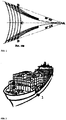
- Illustration. 1 shows a schematic representation of a wave system generated by a ship on the example of a Kelvin wave (according to www.wikipedia.org).
- a hull after EP 1044873 A1 Wave formation can be reduced by over-water, specially shaped surfaces around the boat.
- large ships can not benefit because they would be extremely large.
- the patent DE 688 544 from 1940 proposes a system in which the waves are to be taken in part by a so-called Wellenschlucker. It is a second side wall located at the bow, wherein in the space between the actual side wall and the additional the resulting bow wave is to be partially caught.
- hydrofoils Alternative ways to save energy are provided by hydrofoils.
- the research on hydrofoils ie the use of wings to lift a boat out of the water and in this way to reduce the characteristic impedance, such as the published patent application DE 1 506 260 from 1969 shows, relatively old. Especially for ships that have to carry large loads, hydrofoils are rarely / not suitable.
- a system that recovers energy from ocean waves to drive a ship was implemented in the ship Suntory Mermaid II and successfully tested in the Indian Ocean. It can be seen in particular that energy can be drawn from a sea wave via a wing or hydrofoil. However, since sea waves are not stationary relative to a ship, but are mobile, the energy yield is relatively low and the construction of the hydrofoil must also be designed to be mobile in order to obtain an energy yield.
- German patent DE 931 090 B from 1955, as well as the US patent US20150344106 A1 try to minimize the bow wave by means of a vertical hydrofoil to save drive energy.
- both patents clearly refer to the mid-ship bow area.
- the wave front which arises due to the sloping into the parallel region overflowing nose flanks, can not be achieved by the methods described in these patents in terms of energy conservation.
- the system proposed here deals with a clearly different problem:
- the goal is not a wave at the (central / midships) bow area does not arise, but from the standing wave which has formed at the entire bow area, the maximum energy to regain, by extinguishing the wave in the "expiring" area, ie in the border area between the bow area and the side area ("future parallel area").
- the reason why energy can be recovered from the total wave is that i) the wave has not yet detached from the bow area or hull at this time, ii) that it is a wave standing relative to the ship's hull, and in order that a system such as that described can be devised, having a maximum recovery effect, and iii) the system can be constructed in both horizontal and vertical, as well as combined, arrangement to provide the optimum effect in relation to the hull shape to achieve fuel savings. It is not only important to note the wave minimization in the construction, but also on the parallelogram of forces created by a wing and may have a contribution in the direction of travel, which can also be used for fuel savings.
- the system in terms of its width minimization solely due to the speed of travel, and due to the small width in the following areas, has disadvantages which would have a system which would not be based on recovery, but on prior correction of the wave problem: i) increase effects in the bow area, ii) Frictional drag due to hydrofoil size; iii) Sea surface fatigue effects (especially when the bow hits a large trough).
- a device in order to achieve the entire propulsion wave in the bow area in the sense of energy saving, a device must be mounted on the side of the ship, ie in or near the border area between the bow area and the parallel area of the fuselage (relative to the waterline). introduces a hydrofoil into the water which creates a wave which then interferes with the natural waves produced by the entire bow area of the ship, so that the natural waves of the displacer are almost extinguished when traveling through the water. Illustration. 2 shows the position of such a hydrofoil to minimize the (overall) bow wave.
- FIG. 2 1 denotes a hydrofoil positioned on the side of a ship.
- the geometry of such here for the bow wave designed hydrofoil
- This can be introduced by under or over the water to the hull, especially hull, mounted brackets, or directly into the water, so does not have to go out as shown by the hull in its entirety, but can be separated from this spatially.
- Mechanisms for the movable positioning of the system are also not shown.
- the positioning of the hydrofoil on the entire side wall can vary. Of course, several Hydrofoils per ship side are conceivable. These may be in horizontal form, in recessive form, or in a combined form.
- the inventive design of the hydrofoils it is possible to reduce or eliminate the formation of waves and thus the inaccuracies attributable to it. In particular, a considerable saving in drive energy for the entire ship succeeds.
- the design of the hydrofoil should take into account that at the remote from the bow Midship area Hydrofoil must extinguish the own wave here by interference.
- the wave crest and the ship's direction are not perpendicular to each other here. at For a horizontal hydrofoil, therefore, the external shape (“lateral and horizontal direction”) of the hydrofoil should follow the wave crest, while the wing structure, ie the change in height (“vertical direction”), should be laid out according to the shipping direction.
- hydrofoils eg rigid, foldable, retractable or swingable
- hydrofoils are only required to be attached close to the point of origin of the waves, possibly even in the boundary layer region of the laminar flow, which produce a wave which corresponds to the given bow wave (or stern wave - the lateral stern wave) - or lateral vertical wave) destructively interferes.
- hydrofoils are installed fixedly or movably, which do not protrude beyond the width of the fuselage and still interfere with the own wave as destructively as possible.
- the invention will be readily usable with non-adjustable hydrofoils only in a certain speed range (e.g., cruise speed).
- a certain speed range e.g., cruise speed
- many commercial vehicles usually move at a constant cruising speed.
- the design of the hydrofoils according to the invention naturally has a larger surface area and correspondingly a higher frictional resistance. Nevertheless, the total resistance (friction resistance + characteristic impedance) is lower, whereby a saving in drive energy can be achieved.
- this can be movable to compensate for larger waves, i. be adjustable, or nachgerebar built.
- a control system for the Hydrofoils can also be used to always achieve optimal drive energy consumption for different speeds, or even for continuous speed changes.
Landscapes
- Chemical & Material Sciences (AREA)
- Engineering & Computer Science (AREA)
- Combustion & Propulsion (AREA)
- Mechanical Engineering (AREA)
- Ocean & Marine Engineering (AREA)
- Physics & Mathematics (AREA)
- Fluid Mechanics (AREA)
- Other Liquid Machine Or Engine Such As Wave Power Use (AREA)
Applications Claiming Priority (1)
| Application Number | Priority Date | Filing Date | Title |
|---|---|---|---|
| DE102017007809.2A DE102017007809A1 (de) | 2017-08-17 | 2017-08-17 | System zur Veränderung der Eigenwelle eines Bootes |
Publications (1)
| Publication Number | Publication Date |
|---|---|
| EP3444178A1 true EP3444178A1 (fr) | 2019-02-20 |
Family
ID=62985867
Family Applications (1)
| Application Number | Title | Priority Date | Filing Date |
|---|---|---|---|
| EP18000604.1A Withdrawn EP3444178A1 (fr) | 2017-08-17 | 2018-07-17 | Système de changement de vague propre d'un bateau |
Country Status (2)
| Country | Link |
|---|---|
| EP (1) | EP3444178A1 (fr) |
| DE (1) | DE102017007809A1 (fr) |
Families Citing this family (1)
| Publication number | Priority date | Publication date | Assignee | Title |
|---|---|---|---|---|
| DE102018002823A1 (de) | 2018-04-07 | 2019-10-10 | Casjen Merkel | System zur Veränderung der Eigenwelle eines Bootes mittels des Magnus-Effekts |
Citations (5)
| Publication number | Priority date | Publication date | Assignee | Title |
|---|---|---|---|---|
| DE2814260A1 (de) * | 1978-04-03 | 1979-10-11 | Horst Dipl Ing Tuppeck | Leitflaechen fuer wasserfahrzeuge |
| GB1561124A (en) * | 1976-08-31 | 1980-02-13 | Hydroconic Ltd | Twin hull marine vessels |
| JP2001219894A (ja) * | 2000-02-08 | 2001-08-14 | Nkk Corp | 砕氷船 |
| JP2005193747A (ja) * | 2004-01-06 | 2005-07-21 | Universal Shipbuilding Corp | 動揺抑制装置およびこれを装備した船舶 |
| JP2014004910A (ja) * | 2012-06-25 | 2014-01-16 | Yasuo Ueno | 船舶用推進装置 |
Family Cites Families (6)
| Publication number | Priority date | Publication date | Assignee | Title |
|---|---|---|---|---|
| DE688544C (de) * | 1936-10-25 | 1940-09-17 | Erich Grundt Dipl Ing | Buganbau fuer Schiffe |
| DE931090C (de) * | 1952-11-11 | 1955-08-01 | Heinrich Kuckuck | Vorrichtung zur Verminderung der Bugwelle bei Wasserfahrzeugen |
| DE1506260C3 (de) * | 1967-03-29 | 1974-03-14 | Christopher Old Bosham Sussex Hook (Grossbritannien) | Einrichtung zur Schlinger- und Stampfstabilisierung eines Tragflügelbootes |
| US4080922A (en) * | 1975-09-08 | 1978-03-28 | Brubaker Curtis M | Flyable hydrofoil vessel |
| DE4332358C2 (de) * | 1993-09-23 | 1997-03-06 | Nissen Jens Peter Dipl Ing | Verfahren und Vorrichtung zur wirkungsvolleren Umsetzung der Antriebsenergien von Wasserfahrzeugen in Geschwindigkeit |
| AT406143B (de) | 1997-10-16 | 2000-02-25 | Eder Theodor | Schiffskörper |
-
2017
- 2017-08-17 DE DE102017007809.2A patent/DE102017007809A1/de not_active Withdrawn
-
2018
- 2018-07-17 EP EP18000604.1A patent/EP3444178A1/fr not_active Withdrawn
Patent Citations (5)
| Publication number | Priority date | Publication date | Assignee | Title |
|---|---|---|---|---|
| GB1561124A (en) * | 1976-08-31 | 1980-02-13 | Hydroconic Ltd | Twin hull marine vessels |
| DE2814260A1 (de) * | 1978-04-03 | 1979-10-11 | Horst Dipl Ing Tuppeck | Leitflaechen fuer wasserfahrzeuge |
| JP2001219894A (ja) * | 2000-02-08 | 2001-08-14 | Nkk Corp | 砕氷船 |
| JP2005193747A (ja) * | 2004-01-06 | 2005-07-21 | Universal Shipbuilding Corp | 動揺抑制装置およびこれを装備した船舶 |
| JP2014004910A (ja) * | 2012-06-25 | 2014-01-16 | Yasuo Ueno | 船舶用推進装置 |
Also Published As
| Publication number | Publication date |
|---|---|
| DE102017007809A1 (de) | 2019-02-21 |
Similar Documents
| Publication | Publication Date | Title |
|---|---|---|
| DE69218622T2 (de) | Avanciertes seeboot für hohe geschwindigkeiten in oder über grobe see | |
| DE69802283T2 (de) | Schnelles einrumpfschiff mit heckstabilisatoren | |
| DE102005028447B4 (de) | Schiff | |
| EP2616318B1 (fr) | Navire avec une passerelle d'embarquement | |
| DE69208337T2 (de) | Mehrrumpfschiff | |
| DE69527071T2 (de) | Gleitboot | |
| DE60107236T2 (de) | Bodeneffekttragflügelfahrzeug mit Endscheiben | |
| EP0182314A2 (fr) | Véhicule à coussin d'air du type catamaran | |
| DE2931020A1 (de) | Staufluegelboot | |
| DE602004003376T2 (de) | Flugzeug mit störklappen lediglich an der oberseite | |
| DE3319127A1 (de) | Luftkissenfahrzeug | |
| DE1506810B2 (de) | Vorrichtung zur steuerung und oder stabilisierung eines luft oder wasserfahrzeugs | |
| EP1044873B1 (fr) | Oeuvres vives d'une coque de bateau | |
| DE69200417T2 (de) | Rumpfstruktur für Mehrrumpfschiffe. | |
| DE2500008A1 (de) | Tragfluegelboot | |
| WO2010099971A2 (fr) | Voile haute performance flexible | |
| DE19752170C2 (de) | Im Bugbereich eines mehrrumpfigen Wasserfahrzeugs angeordnete Auftriebsvorrichtung | |
| EP0648668A1 (fr) | Bateau à grande vitesse, en particulier un ferry | |
| DE102014002537A1 (de) | Hydrofoil-Rumpfunterbau für wasserstartende Bodeneffekt-/Stauflügelfahrzeuge | |
| DE102020106224A1 (de) | Aquadynamischeres Wasserfahrzeug mit fortschrittlicherer Rumpfanordnung | |
| DE2805647A1 (de) | Schiffsrumpf | |
| DE102017007809A1 (de) | System zur Veränderung der Eigenwelle eines Bootes | |
| DE29908430U1 (de) | Schnelles seegehendes Schiff | |
| DE202013004518U1 (de) | Wellenreiter-Schiffsrumpf | |
| EP2769909A2 (fr) | Carène et coque de bateau ainsi que bateau doté d'une coque |
Legal Events
| Date | Code | Title | Description |
|---|---|---|---|
| STAA | Information on the status of an ep patent application or granted ep patent |
Free format text: STATUS: EXAMINATION IS IN PROGRESS |
|
| PUAI | Public reference made under article 153(3) epc to a published international application that has entered the european phase |
Free format text: ORIGINAL CODE: 0009012 |
|
| 17P | Request for examination filed |
Effective date: 20180806 |
|
| AK | Designated contracting states |
Kind code of ref document: A1 Designated state(s): AL AT BE BG CH CY CZ DE DK EE ES FI FR GB GR HR HU IE IS IT LI LT LU LV MC MK MT NL NO PL PT RO RS SE SI SK SM TR |
|
| AX | Request for extension of the european patent |
Extension state: BA ME |
|
| STAA | Information on the status of an ep patent application or granted ep patent |
Free format text: STATUS: THE APPLICATION IS DEEMED TO BE WITHDRAWN |
|
| 18D | Application deemed to be withdrawn |
Effective date: 20190430 |
|
| STAA | Information on the status of an ep patent application or granted ep patent |
Free format text: STATUS: EXAMINATION IS IN PROGRESS |
|
| STAA | Information on the status of an ep patent application or granted ep patent |
Free format text: STATUS: REQUEST FOR EXAMINATION WAS MADE |
|
| D18D | Application deemed to be withdrawn (deleted) | ||
| STAA | Information on the status of an ep patent application or granted ep patent |
Free format text: STATUS: REQUEST FOR EXAMINATION WAS MADE |
|
| STAA | Information on the status of an ep patent application or granted ep patent |
Free format text: STATUS: EXAMINATION IS IN PROGRESS |
|
| RBV | Designated contracting states (corrected) |
Designated state(s): AL AT BE BG CH CY CZ DE DK EE ES FI FR GB GR HR HU IE IS IT LI LT LU LV MC MK MT NL NO PL PT RO RS SE SI SK SM TR |
|
| 17Q | First examination report despatched |
Effective date: 20200630 |
|
| 17Q | First examination report despatched |
Effective date: 20200702 |
|
| R17C | First examination report despatched (corrected) |
Effective date: 20201209 |
|
| STAA | Information on the status of an ep patent application or granted ep patent |
Free format text: STATUS: THE APPLICATION IS DEEMED TO BE WITHDRAWN |
|
| R18D | Application deemed to be withdrawn (corrected) |
Effective date: 20210420 |