EP3444228A1 - Corps multicouche, procédé de préparation associé et utilisation associée - Google Patents
Corps multicouche, procédé de préparation associé et utilisation associée Download PDFInfo
- Publication number
- EP3444228A1 EP3444228A1 EP17781867.1A EP17781867A EP3444228A1 EP 3444228 A1 EP3444228 A1 EP 3444228A1 EP 17781867 A EP17781867 A EP 17781867A EP 3444228 A1 EP3444228 A1 EP 3444228A1
- Authority
- EP
- European Patent Office
- Prior art keywords
- multilayer body
- water
- carbon material
- multilayer
- graphene oxide
- Prior art date
- Legal status (The legal status is an assumption and is not a legal conclusion. Google has not performed a legal analysis and makes no representation as to the accuracy of the status listed.)
- Granted
Links
Images




Classifications
-
- F—MECHANICAL ENGINEERING; LIGHTING; HEATING; WEAPONS; BLASTING
- F24—HEATING; RANGES; VENTILATING
- F24S—SOLAR HEAT COLLECTORS; SOLAR HEAT SYSTEMS
- F24S10/00—Solar heat collectors using working fluids
- F24S10/80—Solar heat collectors using working fluids comprising porous material or permeable masses directly contacting the working fluids
-
- C—CHEMISTRY; METALLURGY
- C02—TREATMENT OF WATER, WASTE WATER, SEWAGE, OR SLUDGE
- C02F—TREATMENT OF WATER, WASTE WATER, SEWAGE, OR SLUDGE
- C02F1/00—Treatment of water, waste water, or sewage
- C02F1/02—Treatment of water, waste water, or sewage by heating
- C02F1/04—Treatment of water, waste water, or sewage by heating by distillation or evaporation
- C02F1/14—Treatment of water, waste water, or sewage by heating by distillation or evaporation using solar energy
-
- B—PERFORMING OPERATIONS; TRANSPORTING
- B01—PHYSICAL OR CHEMICAL PROCESSES OR APPARATUS IN GENERAL
- B01D—SEPARATION
- B01D1/00—Evaporating
- B01D1/0011—Heating features
- B01D1/0029—Use of radiation
- B01D1/0035—Solar energy
-
- C—CHEMISTRY; METALLURGY
- C02—TREATMENT OF WATER, WASTE WATER, SEWAGE, OR SLUDGE
- C02F—TREATMENT OF WATER, WASTE WATER, SEWAGE, OR SLUDGE
- C02F1/00—Treatment of water, waste water, or sewage
- C02F1/02—Treatment of water, waste water, or sewage by heating
- C02F1/04—Treatment of water, waste water, or sewage by heating by distillation or evaporation
- C02F1/048—Purification of waste water by evaporation
-
- F—MECHANICAL ENGINEERING; LIGHTING; HEATING; WEAPONS; BLASTING
- F24—HEATING; RANGES; VENTILATING
- F24S—SOLAR HEAT COLLECTORS; SOLAR HEAT SYSTEMS
- F24S70/00—Details of absorbing elements
- F24S70/10—Details of absorbing elements characterised by the absorbing material
-
- C—CHEMISTRY; METALLURGY
- C02—TREATMENT OF WATER, WASTE WATER, SEWAGE, OR SLUDGE
- C02F—TREATMENT OF WATER, WASTE WATER, SEWAGE, OR SLUDGE
- C02F2103/00—Nature of the water, waste water, sewage or sludge to be treated
- C02F2103/08—Seawater, e.g. for desalination
-
- C—CHEMISTRY; METALLURGY
- C02—TREATMENT OF WATER, WASTE WATER, SEWAGE, OR SLUDGE
- C02F—TREATMENT OF WATER, WASTE WATER, SEWAGE, OR SLUDGE
- C02F2201/00—Apparatus for treatment of water, waste water or sewage
- C02F2201/009—Apparatus with independent power supply, e.g. solar cells, windpower or fuel cells
-
- F—MECHANICAL ENGINEERING; LIGHTING; HEATING; WEAPONS; BLASTING
- F24—HEATING; RANGES; VENTILATING
- F24S—SOLAR HEAT COLLECTORS; SOLAR HEAT SYSTEMS
- F24S10/00—Solar heat collectors using working fluids
- F24S10/10—Solar heat collectors using working fluids the working fluids forming pools or ponds
- F24S10/17—Solar heat collectors using working fluids the working fluids forming pools or ponds using covers or floating solar absorbing elements
-
- F—MECHANICAL ENGINEERING; LIGHTING; HEATING; WEAPONS; BLASTING
- F24—HEATING; RANGES; VENTILATING
- F24S—SOLAR HEAT COLLECTORS; SOLAR HEAT SYSTEMS
- F24S80/00—Details, accessories or component parts of solar heat collectors not provided for in groups F24S10/00-F24S70/00
- F24S2080/01—Selection of particular materials
- F24S2080/013—Foams
-
- F—MECHANICAL ENGINEERING; LIGHTING; HEATING; WEAPONS; BLASTING
- F24—HEATING; RANGES; VENTILATING
- F24S—SOLAR HEAT COLLECTORS; SOLAR HEAT SYSTEMS
- F24S80/00—Details, accessories or component parts of solar heat collectors not provided for in groups F24S10/00-F24S70/00
- F24S2080/01—Selection of particular materials
- F24S2080/014—Carbone, e.g. graphite
-
- F—MECHANICAL ENGINEERING; LIGHTING; HEATING; WEAPONS; BLASTING
- F24—HEATING; RANGES; VENTILATING
- F24S—SOLAR HEAT COLLECTORS; SOLAR HEAT SYSTEMS
- F24S80/00—Details, accessories or component parts of solar heat collectors not provided for in groups F24S10/00-F24S70/00
- F24S80/60—Thermal insulation
- F24S80/65—Thermal insulation characterised by the material
-
- Y—GENERAL TAGGING OF NEW TECHNOLOGICAL DEVELOPMENTS; GENERAL TAGGING OF CROSS-SECTIONAL TECHNOLOGIES SPANNING OVER SEVERAL SECTIONS OF THE IPC; TECHNICAL SUBJECTS COVERED BY FORMER USPC CROSS-REFERENCE ART COLLECTIONS [XRACs] AND DIGESTS
- Y02—TECHNOLOGIES OR APPLICATIONS FOR MITIGATION OR ADAPTATION AGAINST CLIMATE CHANGE
- Y02A—TECHNOLOGIES FOR ADAPTATION TO CLIMATE CHANGE
- Y02A20/00—Water conservation; Efficient water supply; Efficient water use
- Y02A20/20—Controlling water pollution; Waste water treatment
- Y02A20/208—Off-grid powered water treatment
- Y02A20/212—Solar-powered wastewater sewage treatment, e.g. spray evaporation
-
- Y—GENERAL TAGGING OF NEW TECHNOLOGICAL DEVELOPMENTS; GENERAL TAGGING OF CROSS-SECTIONAL TECHNOLOGIES SPANNING OVER SEVERAL SECTIONS OF THE IPC; TECHNICAL SUBJECTS COVERED BY FORMER USPC CROSS-REFERENCE ART COLLECTIONS [XRACs] AND DIGESTS
- Y02—TECHNOLOGIES OR APPLICATIONS FOR MITIGATION OR ADAPTATION AGAINST CLIMATE CHANGE
- Y02E—REDUCTION OF GREENHOUSE GAS [GHG] EMISSIONS, RELATED TO ENERGY GENERATION, TRANSMISSION OR DISTRIBUTION
- Y02E10/00—Energy generation through renewable energy sources
- Y02E10/40—Solar thermal energy, e.g. solar towers
- Y02E10/44—Heat exchange systems
-
- Y—GENERAL TAGGING OF NEW TECHNOLOGICAL DEVELOPMENTS; GENERAL TAGGING OF CROSS-SECTIONAL TECHNOLOGIES SPANNING OVER SEVERAL SECTIONS OF THE IPC; TECHNICAL SUBJECTS COVERED BY FORMER USPC CROSS-REFERENCE ART COLLECTIONS [XRACs] AND DIGESTS
- Y02—TECHNOLOGIES OR APPLICATIONS FOR MITIGATION OR ADAPTATION AGAINST CLIMATE CHANGE
- Y02W—CLIMATE CHANGE MITIGATION TECHNOLOGIES RELATED TO WASTEWATER TREATMENT OR WASTE MANAGEMENT
- Y02W10/00—Technologies for wastewater treatment
- Y02W10/30—Wastewater or sewage treatment systems using renewable energies
- Y02W10/37—Wastewater or sewage treatment systems using renewable energies using solar energy
Definitions
- the invention belongs to the field of light absorption, and particularly relates to a multilayer body as well as a preparation method and application thereof.
- the shortage of fresh water resources has become one of the most urgent problems in modern age. It is an effective way to obtain fresh water resources by desalting seawater.
- the method for desalting seawater mainly comprises distillation methods, desalting by using membranes, crystallization methods, desalting by using a solvent to extract, ion exchange methods and the like.
- the method that desalting seawater by using solar energy has the advantages of being clean, green and low in carbon, which makes this method a promising solution for producing fresh water.
- water Since water has high reflectivity and transmissivity, when it is directly irradiated by sunlight, it cannot efficiently utilize solar energy and steam cannot be efficiently generated.
- people use material having a relatively high optical absorbance as a light absorption body to absorb light energy. The light energy absorbed by the absorption body is then transferred to the water body in a form of heat energy, and then the water is heated to generate steam.
- nanoparticles have been used as light absorbers.
- nanoparticles are dispersed in water.
- the nanoparticles can generate heat energy to heat the water.
- the water can be evaporated effectively.
- porous materials have been used as light absorbers.
- porous materials with high optical absorbance are covered on the surface of water.
- the porous materials can generate heat energy to heat the water. Accordingly, the water can be evaporated effectively.
- the inventor has found that the light absorber adopted in the prior art has disadvantages including complicated preparation process and high cost, which make them unsuitable for large scale production and application.
- the inventors obtain a multilayer body by combing a carbon material layer (the carbon material may comprise one or more of the following: graphite, graphene, graphene oxide, graphene a chemical functional group and carbon nanotubes) with a water permeable base body.
- This multilayer body can be used as a light absorber to absorb light energy and to evaporate liquid.
- the multilayer body is easy to prepare and low in cost, which make it suitable for large scale production and application.
- the inventors have further improved the base body of the multilayer body.
- Base bodies which are water permeable and have relatively low thermal conductivity were produced. These multilayer bodies demonstrate a relatively high efficiency for generating water vapor and a relatively high transfer efficiency of solar energy.
- One object of the disclosure is to provide a multilayer body. Another object of the disclosure is to provide a multilayer body capable of absorbing light energy for the use of evaporating liquid. Another object of the disclosure is to provide a preparation method of the multilayer body. Another object of the disclosure is to provide a usage (or using method) of a carbon material (the carbon material may comprise one or more of the following: graphite, graphene, graphene oxide, graphene modified by chemical functional groups and carbon nanotubes).
- a multilayer body comprises a water permeable base body and a carbon material layer on the such base body, and the base body is water permeable;
- the carbon material comprises one or more of the following: graphite, graphene, graphene oxide, graphene modified by chemical functional groups and carbon nanotubes.
- a preparation method of a multilayer body comprises the following steps:
- a multilayer body is provided.
- the multilayer body is prepared by the preparation method of a multilayer body according to any embodiment of the disclosure.
- a multilayer body according to the disclosure as a light absorber is provided.
- the use of a carbon material layer according to the discloser as a light absorber is provided.
- the beneficial effects of the disclosure are as follows:
- the multilayer body and/or the preparation method of the multilayer body according to the disclosure have one or more of the following advantages:
- the disclosure provides a multilayer body comprising a base body and a carbon material layer disposed on the base body, wherein the base body is water permeable; the carbon material comprises a substance selected from the group consisting of: graphite, graphene, graphene oxide, graphene a chemical functional group, carbon nanotubes and combinations thereof.
- the disclosure provides a multilayer body, wherein the carbon material comprises graphene oxide.
- the disclosure provides a multilayer body, wherein the carbon material layer comprises a graphene oxide layer.
- the disclosure provides a multilayer body, wherein the graphene oxide layer consists of a plurality of single-layer graphene oxide layers laminated to each other.
- the disclosure provides a multilayer body, wherein the carbon material layer and/or the base body are thermally insulating.
- the disclosure provides a multilayer body, wherein the multilayer body has a thermal conductivity of less than 1 W/(m ⁇ K) in at least a direction (such as the direction perpendicular to a layer face) when wetted with water, preferably less than 0.2 W/(m ⁇ K), and further preferably less than 0.1W/(m ⁇ K).
- the disclosure provides a multilayer body, wherein the carbon material layer has a thermal conductivity of less than 1 W/(m ⁇ K) in at least one direction (such as the direction perpendicular to a layer face) when wetted with water, preferably less than 0.2 W/(m ⁇ K).
- the disclosure provides a multilayer body, wherein the base body has a thermal conductivity of less than 1 W/(m ⁇ K) in at least one direction. (such as the direction perpendicular to a layer face of the multilayer body) when wetted with water, preferably less than 0.2 W/(m ⁇ K), and preferably less than 0.1W/(m ⁇ K)
- the disclosure provides a multilayer body, wherein the multilayer body is water permeable in at least one direction. (such as the direction perpendicular to a layer face)
- the disclosure provides a multilayer body, wherein when the multilayer body is placed on water, the carbon material layer is in liquid connection with the water through the base body, rather than being in direct contact with the surface of the water.
- the disclosure provides a multilayer body, wherein the carbon material layer is hydrophilic.
- the disclosure provides a multilayer body, wherein the carbon material layer is water permeable.
- the disclosure provides a multilayer body, wherein the carbon material layer has a porous structure.
- the disclosure provides a multilayer body, wherein the base body is hydrophilic.
- the disclosure provides a multilayer body, wherein the base body has a porous structure.
- the disclosure provides a multilayer body, wherein the porous structure is a porous capillary structure.
- the disclosure provides a multilayer body, wherein when the multilayer body is placed on the surface of water, water can be conveyed to the carbon material layer by virtue of capillary force provided by the capillary structure of the base body.
- the disclosure provides a multilayer body, wherein the base body comprises a water absorbent material with capillary pores and a material with low thermal conductivity.
- the disclosure provides a multilayer body, wherein the water absorbent material with capillary pores and the material with low thermal conductivity are composited with each other.
- the disclosure provides a multilayer body, wherein the material with low thermal conductivity is wrapped by the water absorbent material with capillary pores.
- the disclosure provides a multilayer body, wherein the material with low thermal conductivity is penetrated by the water absorbent material with capillary pores.
- the disclosure provides a multilayer body, wherein the water absorbent material with capillary pores is porous cellulose or hydrophilic fibers.
- the disclosure provides a multilayer body, wherein the cellulose is cellulose acetate, cellulose nitrate, or mixed cellulose.
- the disclosure provides a multilayer body, wherein the hydrophilic fibers are natural hydrophilic fibers and/or synthetic hydrophilic fibers.
- the natural hydrophilic fibers for example are plant fibers (e.g. cotton fibers, hemp fibers or wood fibers) or animal fibers (e.g. silk or wool).
- the disclosure provides a multilayer body, wherein the water absorbent material with capillary pores has pores having a pore diameter of from 1 to 1000 ⁇ m, for example from 10 to 100 ⁇ m.
- the disclosure provides a multilayer body, wherein the material with low thermal conductivity has a thermal conductivity of less than 1W/(m ⁇ K), preferably less than 0.2 W/(m ⁇ K), and further preferably less than 0.1 W/(m ⁇ K).
- the disclosure provides a multilayer body, wherein the material with low thermal conductivity are selected from the group consisting of polyurethane (foam), rubber, glass wool, aluminum silicate and combinations thereof.
- the disclosure provides a multilayer body, wherein the base body comprises another water permeable material.
- the disclosure provides a multilayer body, wherein the another water permeable material is in contact with the carbon material layer.
- the disclosure provides a multilayer body, wherein the another water permeable material is in contact with the graphene oxide layer.
- the disclosure provides a multilayer body, wherein the another water permeable material is a mixed cellulose ester membrane.
- the disclosure provides a multilayer body, wherein the mixed cellulose ester membrane is a porous polyvinylidene difluoride-polypropylene membrane.
- the disclosure provides a multilayer body, wherein the carbon material layer has a thickness of from 1 to 100 ⁇ m, e.g. from 1 to 10 ⁇ m.
- the disclosure provides a multilayer body, wherein the carbon material layer has a porous structure (e.g. a capillary porous structure), wherein the porous structure has a pore diameter of from 10 to 1000 nm, preferably from 10 to 120 nm, and further preferably from 40 to 80 nm.
- a porous structure e.g. a capillary porous structure
- the disclosure provides a multilayer body, wherein the carbon material layer has pores having a pore diameter of 40 to 80 nm whose total pore volume is 0.01 to 100 cm 3 /g.
- the disclosure provides a multilayer body, wherein the pores having a pore diameter of 40 to 80 nm has a total pore volume is 0.01 to 10 cm 3 /g.
- XPS X-ray photoelectron spectroscopy
- the disclosure provides a multilayer body, wherein the graphene oxide is synthesized by Hummers' method.
- the disclosure provides a multilayer body, wherein, the carbon material layer is obtained by using a wet chemistry method.
- the disclosure provides a multilayer body, wherein the wet chemical method is spin coating, spray coating or liquid deposition.
- the disclosure provides a multilayer body, wherein the base body has a thickness of from 0.1 to 10 cm, preferably from 1 to 5 cm.
- the disclosure provides a multilayer body, wherein the base body has a porous structure (e.g. a capillary porous structure), wherein the porous structure has a pore diameter of preferably from 1 to 1000 ⁇ m; further preferably from 10 to 100 ⁇ m.
- a porous structure e.g. a capillary porous structure
- the porous structure has a pore diameter of preferably from 1 to 1000 ⁇ m; further preferably from 10 to 100 ⁇ m.
- the disclosure provides a multilayer body, wherein the multilayer body is floatable on the surface of water.
- the disclosure provides a multilayer body, wherein the multilayer body is adapted to work under light irradiation.
- the disclosure provides a multilayer body, wherein the multilayer body is adapted to work under light irradiation in a floating state on a liquid.
- the disclosure provides a method for preparing a multilayer body, comprising:
- the disclosure provides a method for preparing a multilayer body, wherein in step a) the carbon material has a size of from 1 nm to 1000 ⁇ m, for example, from 1 nm to 1000 nm, for example, from 1 to 1000 ⁇ m.
- the disclosure provides a method for preparing a multilayer body, wherein the carbon material comprises graphene oxide.
- the disclosure provides a method for preparing a multilayer body, wherein in step b), the coating is spin coating or spray coating.
- the disclosure provides a method for preparing a multilayer body, wherein in step b), the deposition is filtration deposition or vacuum filtration deposition.
- the disclosure provides a method for preparing a multilayer body, wherein step a) comprises synthesizing graphene oxide by using Hummers' method.
- the disclosure provides a method for preparing a multilayer body, wherein the carbon material graphene oxide dispersion liquid in step a) is a graphene oxide dispersion liquid whose solvent is water.
- the disclosure provides a method for preparing a multilayer body, wherein the graphene oxide dispersion liquid in step a) has a concentration of from 1 to 10 mg/mL.
- the disclosure provides a multilayer body, which is prepared by any preparation method according to the disclosure.
- the disclosure provides use of the multilayer body according to the disclosure as a light absorber.
- the disclosure provides use of the carbon material layer as a light absorber, wherein the carbon material comprises a substance selected from the group consisting of graphite, graphite, graphene, graphene oxide, graphene modified by chemical functional groups, carbon nanotubes and combinations thereof.
- the disclosure provides use of a carbon material film as a light absorber, wherein the carbon material comprises graphene oxide.
- the disclosure provides use of a carbon material film as a light absorber, wherein the carbon material film has one or more of the following features:
- the light absorber may be used for evaporating a liquid by using the absorbed light energy.
- the light absorber may be further used for desalting sea water, purifying sewage water, separating different solvent or generating hot water vapor.
- the disclosure provides a multilayer body, wherein the base body comprises a base body and a carbon material layer disposed on the base body, wherein the base body is liquid to permeable; the carbon material comprises a substance selected from the group consisting of graphite, graphene, graphene oxide, graphene modified by chemical functional groups and carbon nanotubes and combinations thereof.
- the carbon material layer has a convex surface.
- the area of the convex surface is 1.2 times or more of the projection area of the convex surface, preferably 1.5 times or more.
- the convex surface is an arc surface, a conical surface or a folded surface.
- the conical surface has a vertex angle of from 60 to 120 degrees.
- the conical surface has a vertex angle of from 80 to 100 degrees.
- the base body comprises a thermally insulating material penetrated by a liquid absorbent material with a capillary structure.
- the base body comprises a polystyrene foam penetrated by a cotton wick.
- the carbon material layer has pores having a pore diameter of from 40 to 80 nm whose total pore volume is from 0.01 to 10 cm 3 /g, preferably 0.01 to 1 cm 3 /g, and further preferably from 0.01 to 0.1 cm 3 /g.
- the disclosure provides a multilayer body, wherein the carbon material layer has a thickness of from 1 to 20 ⁇ m, e.g. from 3 to 8 ⁇ m, and e.g. 4 to 5 ⁇ m.
- the disclosure provides a multilayer body, wherein the carbon material has a particle size of from 0.01 to 10 ⁇ m, for example, from 0.1 to 5 ⁇ m, and for example, from 0.5 to 2 ⁇ m.
- the porous structure has a most frequent pore diameter of from 10 to 120 nm, preferably from 20 to 100 nm, preferably from 40 to 80 nm, and preferably from 40 to 60 nm.
- the carbon material layer has pores having a pore diameter of from 40 to 80 nm whose total pore volume is from 0.01 to 1 cm 3 /g, for example from 0.01 to 0.1 cm 3 /g, and for example from 0.04 to 0.6 cm 3 /g.
- the carbon material has a peak in the range of from 20 to 60 nm in a pore diameter distribution plot, preferably in the range of from 30 to 50 nm.
- the carbon material has only one peak in the range of from 20 to 60 nm in a pore diameter distribution plot, preferably in the range of from 30 to 50 nm.
- the peak thereof has a peak value of from 0.01 to 0.1 cm 3 /g, preferably from 0.03 to 0.08 cm 3 /g, further preferably from 0.04 to 0.06 cm 3 /g, and further preferably from 0.05 to 0.06 cm 3 /g.
- the pore diameter distribution plot is measured according to BJH theory.
- D measured in nm is a variable of a horizontal axis of the plot
- dV/dlogD measured in cm 3 /g is a variable of a vertical axis of the plot, wherein V denotes total pore volume and D denotes pore diameter.
- the carbon material has a specific surface area of form 1 to 4000 m 2 /g, for example from 1 to 1000 m 2 /g, for example from 1 to 500 m 2 /g, for example from 1 to 100 m 2 /g, for example from 1 to 50 m 2 /g, for example from 1 to 10 m 2 /g, and for example from 10 to 30 m 2 /g.
- the disclosure provides a multilayer body which comprises a base body and a black-colored layer disposed on the base body, wherein the base body is liquid permeable and the black colored layer comprises a textile and a black substance.
- the black colored layer is liquid permeable.
- the black colored layer is gas permeable.
- the textile is woven textile or non-woven textile.
- the textile is selected from the group consisting denim, poplin cotton, composite twill, canvas, towel cloth and combinations thereof.
- the textile comprises non-woven textile (also referred to as nonwoven)
- the non-woven textile is a manufactured sheet, web or batt of directionally or randomly orientated fibers, bonded by friction, cohesion, adhesion or combinations thereof.
- the non-woven textile is prepared by a drylaying method (e.g. a carding method or an airlaying method), a polymer extrusion method (e.g. a spinlaying method or a meltdown web method) or a wet method.
- a drylaying method e.g. a carding method or an airlaying method
- a polymer extrusion method e.g. a spinlaying method or a meltdown web method
- a wet method e.g. a spinlaying method or a meltdown web method
- the non-woven textile is prepared by a polymer extrusion method. (e.g. a spinlaying method or a meltdown web method)
- the non-woven textile may have relatively high mechanical strength, relatively large porosity and good hydrophilicity.
- the multilayer body comprising the non-woven textile exhibits relatively high water vapor generation rate and high evaporation efficiency using solar energy.
- the textile has a fabric weight of from 20 to 200 g/m 2 , for example from 40 to 180 g/m 2 , for example from 60 to 160 g/m 2 , for example from 180 to 140 g/m 2 , for example from 100 to 120 g/m 2 .
- the textile contains fibers.
- the textile comprises natural fibers (e.g. cotton, hemp, wool or silk), synthetic fibers or carbon fibers
- the synthetic fibers comprise a material selected from the group consisting of terylene, polypropylene fiber, chinlon, spandex, acrylic fiber and combinations thereof.
- the black colored layer comprises textile selected from the group consisting of terylene non-woven fabric, polypropylene fiber non-woven fabric, chinlon non-woven fabric, spandex non-woven fabric, acrylic nonwoven fabric and combinations thereof.
- the black substance comprises a substance selected from the group consisting of black dye, black powder, black fibers and combinations thereof.
- the carbon material comprises a substance selected from graphite, graphene, graphene oxide, graphene modified by chemical functional groups, carbon nanotubes, carbon black and combination thereof.
- the black colored layer comprises a textile adhered with a black substance.
- the black colored layer comprises a textile covered with a black substance.
- the black colored layer comprises a textile blackened by a black dye.
- the black colored layer and/or the base body are thermally insulating.
- the black colored layer when the multilayer body is placed on the surface of water, the black colored layer is in liquid connection with the surface of water through the base body, rather than in direct contact with the surface of water.
- the multilayer body is placed on the surface of water, the base body with a capillary structure is capable of conveying water to the black colored layer in virtue of capillary force.
- the black colored layer has a thickness of from 1 to 10000 ⁇ m, for example from 1 to 5000 ⁇ m, for example from 1 to 2000 ⁇ m, for example from 1 to 1000 ⁇ m, for example from 1 to 100 ⁇ m, for example from 1 to 10 ⁇ m.
- the textile has a thickness of from 1 to 10000 ⁇ m, for example from 1 to 5000 ⁇ m, for example from 1 to 2000 ⁇ m, for example from 1 to 1000 ⁇ m, for example from 1 to 100 ⁇ m, for example from 1 to 10 ⁇ m.
- the black colored layer has a porous structure (e.g. capillary porous structure) having a pore diameter of from 10 to 1000 nm, preferably from 10 to 120 nm, and further preferably from 40 to 80 nm.
- a porous structure e.g. capillary porous structure having a pore diameter of from 10 to 1000 nm, preferably from 10 to 120 nm, and further preferably from 40 to 80 nm.
- the black colored layer has pores having a pore diameter of from 40 to 80nm whose total pore volume is from 0.01 to 100 cm 3 /g, for example, 0.01 to 10 cm 3 /g, and preferably from 0.01 to 1 cm 3 /g, and preferably from 0.01 to 0.1 cm 3 /g.
- the black colored layer or the black substance has a specific surface area of from 1 to 4000 m 2 /g, for example from 1 to 1000 m 2 /g, for example from 1 to 500 m 2 /g, for example from 1 to 100 m 2 /g, for example from 1 to 50 m 2 /g, for example from 1 to 10 m 2 /g, for example from 10 to 30 m 2 /g.
- the textile and/or black substance is hydrophilic.
- the carbon material layer /black colored layer contains a binder or a hydrophilic substance.
- the carbon material layer /black colored layer contains sodium alginate.
- the black colored layer has a convex surface.
- the area of the convex surface of the black colored layer is 1.2 times of the projection area of the convex surface, preferably 1.5 times or more.
- the convex surface is an arc surface, a conical surface or a folded surface.
- the vertex angle of the conical surface is from 60 to 120 degrees, for example from 80 to 100 degrees.
- the carbon material layer has a convex surface.
- the area of the convex surface of the carbon material layer is 1.2 times of the projection area of the convex surface, preferably 1.5 times or more.
- the convex surface is an arc surface, a conical surface or a folded surface.
- the vertex angle of the conical surface is 60 to 120 degrees, for example 80 to 100 degrees.
- the base body comprises a heat insulation material which is penetrated by a liquid absorbent material with a capillary structure.
- the base body comprises polystyrene foam penetrated by a cotton wick.
- the invention provides a light absorbing device comprising any multilayer body described herein.
- the light absorbing device further comprises a liquid transfer means and/or a heat insulation means; preferably, the liquid transfer means is in contact with the base body; preferably, the heat insulation means wraps all of the base body or part of the base body; preferably, the liquid transfer means comprises a liquid absorbent material with a capillary structure; preferably, the thermal insulation means comprise a material with low thermal conductivity.
- the multilayer body, the base body or the black colored layer is liquid permeable, for example, water permeable.
- the liquid comprises water.
- the liquid absorbent material comprises a water absorbent material with a capillary structure.
- the textile comprises cloth.
- the multilayer body in some of the following examples comprised a base body and a carbon material layer on the base body, wherein the base body was water permeable; the carbon material layer was a graphene oxide layer.
- the graphene oxide was prepared by the following methods:
- a graphene oxide dispersion liquid was prepared by Hummers' method.
- Raw materials flake graphite (30 mesh, Sinopharm Chemical Reagent Co., Ltd., 99.99 wt% purity), 98 wt% concentrated sulfuric acid (analytical reagent /AR, Sinopharm Chemical Reagent Co., Ltd.), 30 wt% hydrogen peroxide (guaranteed reagent /GR, Sinopharm Chemical reagent Co., Ltd.), potassium permanganate (guaranteed reagent/GR, Sinopharm Chemical Reagent Co., Ltd.), 36 wt% hydrochloric acid (guaranteed reagent/GR, Sinopharm Chemical Reagent Co., Ltd.).
- Low-temperature reaction stage 120 mL of concentrated sulfuric acid was added to a 500 mL beaker. The beaker was subsequently put into an ice water bath. When the temperature of the concentrated sulfuric acid reached 0 °C, graphite (5 g) was added to the beaker with stirring. After 30 minutes of stirring, 0.75 g of potassium permanganate was subsequently slowly added to the beaker while stirring and keeping the temperature of the reactants from exceeding 5 °C. After 30 minutes of stirring, 15 g of potassium permanganate was slowly added to the beaker with stirring, and keeping the temperature of the reactants from exceeding 5 °C. The mixture was then stirred for 30 minutes.
- High-temperature reaction stage the beaker containing the mixed solution was stirred for 30 min in a water bath at 98 °C. A 3.5 wt% hydrogen peroxide solution was prepared in advance. After stirring, the mixed solution was taken away from the water bath, and then, 150 mL of the as-prepared 3.5 wt% hydrogen peroxide was added into the aqueous mixture. The resultant material with a color of bright yellow was obtained.
- the resultant material was filtered while it was hot to remove most of the water, strong acid and the like therein. Then, the residual solid was rinsed with a 5 wt% hydrochloric acid solution to remove metal ions therein. Finally, the residual solid was repeatedly rinsed with distilled water until the washing solution had a pH that was substantially neutral, and then, the residual solid was dried in a drying oven for later use.
- Composition wood cellulose
- FIG. 1 is a graph depicting a schematic diagram of multilayer body-1 of Example 1.
- multilayer body-1 comprises a base body 2 and a graphene oxide layer 1 disposed on the base body 2, wherein the base body 2 is a porous mixed cellulose membrane.
- the method for preparing multilayer body-1 includes:
- the base body of multilayer body-1 was a porous mixed cellulose membrane.
- the porous mixed cellulose membrane was hydrophilic, water permeable and had a porous capillary structure.
- the porous capillary structure of the base body was capable of conveying water to the graphene oxide layer by virtue of capillary force.
- the graphene oxide layer was stripped from the porous mixed cellulose membrane to obtain a stripped graphene oxide film.
- the stripped graphene oxide film was subjected to XPS, SEM and pore diameter distribution analysis.
- FIG. 4 is a graph of an X-ray photoelectron spectrum of the graphene oxide layer.
- C-C of aromatic rings at approximately 284.9 eV
- C-O of hydroxyl and epoxy groups at approximately 286.9 eV
- C O of carbonyl group at approximately 288.1 eV
- the multilayer bodies may be fabricated in large scale by methods such as spray coating or spin coating, i.e., spray coating or spin coating a graphene oxide dispersion liquid on a base body having a large surface area. Furthermore, the hydrophilicity of the graphene oxide film was advantageous for water permeation.
- FIG. 5 depicts a scanning electron microscope image of the cross-section of a graphene oxide film of multilayer body-1.
- the graphene oxide film had a thickness of approximately 4 ⁇ m with a clearly multilayered structure. According to the characteristics of the graphene oxide, it can be deduced that the graphene oxide film consisted of a plurality of single-layer graphene oxide sheets, having a thickness of approximately 1 nm, laminated to each other.
- the multilayered structure was advantageous for increasing the thermal resistance of the graphene oxide film, especially the thermal resistance perpendicular to the surface of the graphene oxide film. In fact, the thermal conductivity perpendicular to the surface of the graphene oxide was approximately 0.2 W/mK.
- FIG. 6 is depicts a plot illustrating the total pore volume of the graphene oxide film as a function of pore diameter. As shown in the figure, pores with a pore diameter of 40 nm had the largest total pore volume, which was approximately 0.05 cm 3 /g. Therefore, the typical pore diameter of the graphene oxide film was 40 nm. According to the BET analysis result, it can be concluded that the graphene oxide film had a porous (capillary) structure, which provided convenient channels for water to flow into the graphene oxide film and for water vapor to flow away from the graphene oxide film.
- the specific surface area of the graphene oxide membrane was approximately 28 m 2 /g, as measured by the BET method.
- multilayer body-1 was also subjected to optical absorbance testing. Specifically, multilayer body-1 was wetted with water, and then, the optical absorbance of the graphene oxide layer side of the wetted multilayer body-1 was investigated under AM1.5G standard sunlight (from 200 to 2500 nm in wavelength) using an ultraviolet/visible-light spectrometer.
- Plot 1 in FIG.7 illustrates the power density (W/m 2 /nm) (corresponding to the right vertical axis) of the AM1.5G standard sunlight as a function of wavelength.
- Plot 2 in FIG. 7 illustrates the optical absorbance (%) of multilayer body-1 (corresponding to the left vertical axis) as a function of wavelength.
- the average optical absorbance of the wetted multilayer body-1 under AM1.5G standard sunlight (wavelength ranging from 200 to 2500 nm) was calculated to be 94%. This illustrated that multilayer body-1 (especially the graphene oxide film) had a relatively high optical absorbance under broadband optical irradiation, making it suitable for being used as a light absorber.
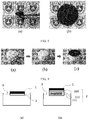
- FIG. 8 includes optical images showing the process of the folding test.
- the image (a) in FIG. 8 is an optical image of multilayer body-1 in a folded state.
- the image (b) in FIG. 8 is an optical image of multilayer body-1, which had been folded 50 times, in an unfolded state.
- 50 times of folding/unfolding brought no notable damage to multilayer body-1.
- the transporting and deploying of multilayer body-1 by folding them during transportation and unfolding them after reaching the destination is convenient. Therefore, multilayer body-1 is suitable for large-scale application. For example, large amounts of multilayer body-Is in a folded state can be transported to the seaside and then be disposed on the surface of the seawater after being unfolded, being used for the evaporation and desalination of seawater.
- FIG. 2 depicts a schematic of multilayer body-2 of example 2.
- Multilayer body-2 comprised a base body 2 and a graphene oxide layer 1 disposed on the base body 2.
- the base body 2 comprised a porous mixed cellulose membrane 210 and a polystyrene foam plate wrapped by a hydrophilic cellulose membrane 220.
- the porous mixed cellulose membrane 210 was disposed between the graphene oxide layer 1 and the polystyrene foam plate 220 wrapped by a hydrophilic cellulose membrane.
- FIG. 3 depicts a schematic of a polystyrene foam plate wrapped by a hydrophilic cellulose membrane 220.
- the polystyrene foam plate 221 wrapped by a hydrophilic cellulose membrane 220 comprised a polystyrene foam plate 221 and a hydrophilic cellulose film 222 wrapping the polystyrene foam plate 221.
- the method for preparing multilayer body-2 included the following steps:
- a polystyrene foam plate (0.04 W/mK thermal conductivity, Nanjing Shengnuoda Novel Material Co., Ltd.) having a thickness of approximately 1.6 cm and a diameter of approximately 3 cm was provided, and the foam plate was wrapped by a hydrophilic cellulose membrane (lignin contained) having a thickness of approximately 50 ⁇ m. Then, the porous mixed cellulose membrane deposited with the graphene oxide layer was laminated to the polystyrene foam plate wrapped by a hydrophilic cellulose membrane, wherein the porous mixed cellulose membrane was disposed between the graphene oxide layer and the polystyrene foam plate wrapped by a hydrophilic cellulose membrane, thereby multilayer body-2 of Example 2 was obtained.
- a hydrophilic cellulose membrane lignin contained
- FIG. 9 depicts optical images showing the assembly process of multilayer body-2.
- Image (a) in FIG. 9 shows a polystyrene foam plate.
- Image (b) in FIG. 9 shows a polystyrene foam plate wrapped by a hydrophilic cellulose membrane.
- Image (c) in FIG. 9 shows the polystyrene foam plate wrapped by a hydrophilic cellulose membrane, upon which a graphene oxide layer was deposited, and constituted multilayer body-2.
- Multilayer body-2 had a base body comprising a polystyrene foam plastic wrapped by a hydrophilic cellulose membrane and further comprised a porous mixed cellulose membrane. Since the hydrophilic cellulose membrane and the porous mixed cellulose membrane were both hydrophilic, water permeable and had a porous capillary structure, the base body of multilayer body-2 was hydrophilic, water permeable and had a porous capillary structure. The base body was capable of transferring water to the graphene oxide layer via capillary force.
- the polystyrene foam had a relatively low thermal conductivity (e.g., approximately 0.04 W/(m ⁇ °C)). Since the base body of multilayer body-2 was formed by a composition of a material with a low thermal conductivity (polystyrene foam) and a material with a capillary porous structure (hydrophilic cellulose membrane), it possessed properties including both thermal insulation and capillary water absorptivity. When multilayer body-2 was floating on the surface of the water, the thermally insulating base body was capable of confining heat to the graphene oxide layer, restraining heat from dissipating into the water body.
- the first flask was provided multilayer body-1
- the second flask was provided multilayer body-2
- the third flask was provided with no multilayer body.
- the multilayer body was floating on the surface of the water, being parallel to the surface of the water.
- the side of the base body of the multilayer body was in contact with the surface of the water (facing downwards), and the side of the graphene oxide layer faced away from the surface of the water (facing upwards).
- water could penetrate through the base body of multilayer body-1 and multilayer body-2, come in contact with the graphene oxide layer and then wet the graphene oxide layer.
- the three Dewar flasks were irradiated by simulated solar radiation.
- the simulated solar irradiation was obtained by the following method: the light generated by a sunlight simulator (Newport 94043A) was filtered by an optical filter to obtain simulated solar radiation conforming to the AM1.5G spectrum standard.
- the optical power (P in ) of the simulated solar radiation was adjusted to 1 kW ⁇ m -2 .
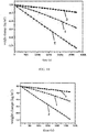
- FIG. 11 is a graph of plots depicting the cumulative mass change of the three Dewar flasks as a function of time, in which plots 1, 2 and 3, respectively, denote the cumulative mass change of the Dewar flask with multilayer body-1, the Dewar flask with multilayer body-2 and the Dewar flask with no multilayer body.
- the weight loss rate of water namely, the water vapor generation rate measured in kg/(m 2 h)
- the water vapor generation rate was determined according to the plots in FIG. 11 .
- the water vapor generation rate was determined according to the data retrieved from the water vapor generation experiments from 1800 to 2700 s.
- the water vapor generation rate measured under simulated solar irradiation (Solar) is denoted by m S .
- the water vapor generation rate in dark was measured and is denoted by m D .
- thermocouples were placed on the upper surface of the multilayer body and the surface of the water to measure the temperature of the generated water vapor, which is denoted by T S (°C.), and the surface temperature of the water, which is denoted by T W (°C.), respectively.
- T S the initial temperature of the surface of the water
- T W the initial temperature of the generated water vapor
- T S45 the surface temperature of the water
- T S45 the temperature of the generated water vapor
- FIG. 13 is a graph depicting plots illustrating the surface temperature of the water and the temperature of the water vapor in the Dewar flask provided with multilayer body-2 as a function of time, wherein plot 1 illustrates the surface temperature of the water as a function of time, and plot 2 illustrates the temperature of the water vapor as a function of time.
- Plot 1 in FIG. 15 illustrates the surface temperature of the water in the Dewar flask provided with multilayer body-1 as a function of time.
- a formula is introduced herein to calculate the solar energy utilization efficiency ( ⁇ ), e.g., the energy utilization efficiency from solar energy to water vapor.
- m denotes the net water vapor generation rate.
- the net water vapor net generation rate (m) the water vapor generation rate under light (M S ) - the water vapor generation rate in the dark (M D ).
- h LV denotes the total liquid-vapor phase-change enthalpy (latent heat enthalpy + sensible heat enthalpy).
- the latent heat enthalpy of water is 2260 J/g
- the sensible heat enthalpy of water is 4.2 J/gK.
- P in denotes the optical power density of the simulated solar radiation.
- the water vapor generation rates and the solar energy utilization efficiencies are shown in table 2
- the surface temperatures of the water and the temperatures of the water vapor are shown in table 3.
- Water vapor generation experiment 2 was the same as water vapor generation experiment 1 except that the Dewar flasks were replaced with beakers.
- FIG. 12 is a graph depicting plots illustrating the cumulative weight changes of three water-filled beakers as a function of time under simulated solar irradiation during 0 ⁇ 2700s, wherein plots 1, 2 and 3, respectively, denote the cumulative weight changes of the water-filled beaker provided with multilayer body-1, the water-filled beaker provided with multilayer body-2 and the water-filled beaker provided no multilayer body as a function of time.
- FIG. 14 is a graph depicting plots illustrating the surface temperature of the water in the water-filled beaker provided with multilayer body-2 as a function of time under light irradiation, wherein plot 1 denotes the surface temperature of the water as a function of time, and plot 2 denotes the temperature of the water vapor as a function of time.
- Plot 2 in FIG. 15 illustrates the surface temperature of the water in the water-filled beaker that was provided with multilayer body-1 under light irradiation.
- the water vapor generation rates and the solar energy utilization efficiencies are shown in Table 2, and the surface temperature of the water and the temperature of the water vapor are shown in Table 3.
- multilayer body-1 and multilayer body-2 are further interpreted according to the data in Table 2 and Table 3.
- Images (a) and (b) in FIG. 10 depict multilayer body-1 and multilayer body-2 floating on the surface of the water 3.
- the base body 2 of multilayer body-1 was a porous cellulose filter membrane; the base body 2 of multilayer body-2 comprised a porous cellulose membrane filter 210 and a polystyrene foam plate 221 wrapped by a hydrophilic cellulose film 222.
- the graphene oxide layer 1 of multilayer body-2 was in liquid connection with the surface of the water 3, instead of being in direct contact with the surface of the water 3.
- This structure was advantageous for confining heat to the graphene oxide layer and restraining heat from dissipating to the surface of the water 3. Therefore, the efficient evaporation of water and efficient utilization of energy are facilitated.
- the base body 2 may further contain a material with a low thermal conductivity (such as a polystyrene foam plate 221), which was further beneficial for heat localization.
- the graphene oxide film showed the following advantages as a light absorber: first, the graphene oxide film had a relatively high optical absorbance for light with a wide wavelength range; second, the porous structure of the graphene oxide membrane provided convenient channels for the inflow of water and outflow of water vapor; third, the graphene oxide film membrane had a low thermal conductivity in a direction that perpendicular to a surface of the membrane face so that it was favorable for keeping heat from dissipating into water; fourth, the graphene oxide film was hydrophilic, water permeable and had a porous capillary structure, so that it was easy for the graphene oxide film to absorb water and discharge water vapor when used as a light absorber; fifth, the hydrophilicity of the graphene oxide enabled the graphene oxide to be easily dispersed in an aqueous solution during the preparation of multilayer bodies, which is advantageous for the large-scale production of multilayer bodies.
- the highest water vapor generation rate was achieved in experiments in which multilayer body-2 was provided, no matter whether in a Dewar flask or in a beaker.
- a water vapor generation rate of approximately 1.45 kg/(m 2 h) was achieved in a Dewar flask provided with multilayer body-2 under light irradiation, which was approximately twice that obtained with a Dewar flask provided with multilayer body-1 under identical conditions and was 6 times that obtained with a Dewar flask provided with no multilayer body.
- multilayer body-2 has a structure that is advantageous for achieving a higher water vapor generation rate and higher solar energy utilization efficiency.
- the heat generated by the graphene oxide layer was confined to the multilayer body instead of dissipating into the surface of the water.
- multilayer body-2 When floating on the surface of the water as a light absorber, multilayer body-2 was capable of generating water vapor (39 ⁇ 40 °C), meanwhile, the surface temperature of the water remained almost unchanged.
- the temperature difference between the upper surface and the lower surface of the multilayer body, the thickness of the multilayer body and the heat transmitted through the multilayer body in unit time was known.
- the thermal conductivity of the whole multilayer body-2 was calculated to be approximately 0.03 W/mK based on the Fourier law. This illustrates that multilayer body-2, including its base body, had a relatively low thermal conductivity in the wet state.
- the temperature of multilayer body-2 rose from 12.9 °C to 32.1 °C within 1 minute into the light irradiation experiment. At 45 min into the experiment, the temperature rapidly rose to 38.8 °C. The temperature of multilayer body-1 rose from 14.4 °C to 19.9 °C within 1 minute into the light irradiation experiment. At 45 min into the experiment, the temperature of multilayer body-1 rose to 30.7 °C. This illustrates that the graphene oxide layer was capable of reaching a relatively high temperature when irradiated by light having a power density of 1 kW • m -2 . It can be concluded that multilayer body-2 can be heated up fast and can stably retain a relatively high temperature, which is advantageous for the rapid generation and volatilization of water vapor.
- multilayer body-1 and multilayer body-2 both exhibited relatively high water vapor generation rates and high optical absorbances. This illustrates that the graphene oxide layer is suitable as a light absorber. Furthermore, the base body of multilayer body-2 had a better performance of thermal insulation, which resulted in (1) a higher water vapor generation rate, (2) a higher solar energy utilization efficiency, (3) a higher temperature of water vapor, (4) a higher heat-up speed and a higher stable temperature, and (5) a minor temperature change at the surface of the water.
- Multilayer body-2 was used to evaporate three types of simulated seawater according to the steps in water vapor generation experiment 4 (wherein the container was a beaker). The evaporated water vapor was condensed and collected to obtain desalted seawater.
- the three types of simulated seawater were North Sea seawater (with a NaCl content of 1.4 wt%), Red Sea seawater (with a NaCl content of 4.1 wt%) and global seawater whose salt content equaled the global average value (with a NaCl content of 3.5 wt%).
- multilayer body-2 can be used for seawater desalination.
- the simulated seawater had a salt content after desalination.
- multilayer body-2 had good cycling stability.
- the water vapor generation rate remained stable even after a longtime light irradiation cycling experiment with multiple cycles.
- FIG. 16 contains optical images of multilayer bodies 810, 820 and 830 in water-filled beakers.
- multilayer body 810 included a carbon material layer 1 and a base body.
- the carbon material layer 1 was a planar graphene oxide layer prepared according to the method described in Example 1.
- the base body was a porous mixed cellulose membrane, which was laminated with the carbon material layer 1.
- the diameter of multilayer body 810 was approximately 4.5 cm.
- multilayer body 820 included a carbon material layer 1 and a base body, in which the carbon material layer 1 was a planar graphene oxide layer prepared according to the method described in example 1.
- the base body comprised a porous mixed cellulose membrane, which was laminated with the carbon material layer.
- the base body was further composed of a polystyrene foam 823 (with a thermal conductivity of 0.03 W/mK) having a thickness of 5 cm and a diameter of 4.5 cm.
- the polystyrene foam 823 was penetrated by a cylindrical cotton wick 822 having a diameter of approximately 7 mm. One end of the cotton wick 822 was in contact with the porous mixed cellulose membrane.
- a multilayer body 830 comprised a carbon material layer 831 and a base body.
- the carbon material layer was a graphene oxide layer prepared according to the method described in example 1, with the graphene oxide layer having a convex shape.
- the base body comprised a porous mixed cellulose membrane, which was laminated with the carbon material layer 1.
- the convex surface of the carbon material layer 831 was a conical surface with a vertex angle of approximately 90 degrees, and the diameter of the bottom of the conical surface of the carbon material layer was approximately 4.5 cm.
- the base body was further composed of a polystyrene foam 833 having a thickness of 1 cm and a diameter of 4.5 cm (with a thermal conductivity of 0.03 W/mK).
- the polystyrene foam was penetrated by a cylindrical cotton wick 822 having a diameter of 7 mm and a height of approximately 6 mm. One end of the cotton wick 822 was in contact with the porous mixed cellulose membrane.
- the environment temperature was 16 °C; the humidity was 60%.
- Beakers were provided as containers. Three water-filled beakers having an inner diameter of approximately 4.5 cm and a height of approximately 5 cm were provided, each of them containing the same amount of water (approximately 60 mL).
- Multilayer bodies 810, 820 and 830 were floating on the surface of the water in the beakers, with the side of the graphene oxide layer facing away from the surface of the water (facing upwards), and the side of the base body being in contact with the surface of the water (facing downwards). When the multilayer body was placed on the surface of the water, the graphene oxide layer could be wetted by the water permeating through the base body.
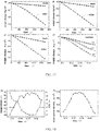
- Graphs (a), (b) and (c) in FIG. 17 illustrate the cumulative weight change of the beakers provided with multilayer bodies 810, 820 and 830 as a function of time under light irradiation or in the dark.
- the weight loss rate of water the amount of the generated water vapor by mass measured in kg/(m 2 h) can be obtained.
- the water vapor generation rate was calculated according to the measured data of the water vapor generation amount.
- M S denotes the water vapor generation rate under light irradiation (Solar)
- M D denotes the water vapor generation rate in the dark (Dark).
- Table 7 The results are shown in table 7:
- multilayer body 830 exhibited a higher water vapor generation rate than did multilayer bodies 810 and 820, no matter whether under light irradiation or in the dark.
- the base body of multilayer body 820 comprised a polystyrene foam layer, which imparted upon multilayer body 820 a good thermal insulating performance. Therefore, multilayer body 820 exhibited a higher water vapor generation rate than did multilayer body 810.
- FIG. 18 contains graph (a) illustrating the temperature and humidity of the day of this experiment as a function of time, and graph (b) illustrating the solar power density of that day as a function of time.
- Graph (d) of FIG. 17 illustrates the water vapor generation rates of the water-filled beakers provided with multilayer bodies 810, 820, and 830 under irradiation of outdoor sunlight. These water vapor generation rates were 0.8 Kg/m 2 h, 1.4 Kg/m 2 h and 2.0 Kg/m 2 h, respectively.
- multilayer body 830 compared to those of multilayer bodies 810 or 820, whose carbon material layer had a planar shape, multilayer body 830, whose carbon material layer had a convex shape, had a larger area for receiving light under the same occupied area, which was beneficial for absorbing more light. Therefore, multilayer body 830 had the virtue of exhibiting a higher solar energy utilization efficiency.
- the carbon material layer having a convex surface especially a conical surface was sufficiently capable of utilizing sunlight radiated at different angles so that it had a low dependency on the angle of sunlight.
- multilayer bodies 830 and 810 were capable of absorbing approximately 25% more light than could multilayer body 810 outdoors.
- Multilayer body-3 was provided in example 11 and comprised a base body and a black-colored layer deposited on the base body.
- the black-colored layer was a nonwoven textile layer whose surface was coated with carbon black.
- the size and the preparation method of the nonwoven textile layer were as follows:
- the nonwoven textile (purchased from Guangdong Jiaxinda Co., Ltd., 120 g/m 2 of fabric weight): a melt-blown nonwoven textile mainly made of polyester fiber in the shape of a circle with a diameter of 4.5 cm and having a thickness of 0.8 mm.
- the surface of one side of the nonwoven textile was spray painted with carbon black powder (Degussa Germany, Printex U) with a painting thickness of approximately 0.8 mm.
- carbon black powder (Degussa Germany, Printex U) with a painting thickness of approximately 0.8 mm.
- the mixture was subjected to ultrasonication for two hours in an ultrasonic dispersion machine, followed by being heated for half an hour with stirring to obtain a spraying liquid. Before use, the spraying liquid was subjected to ultrasonication for half an hour followed by being evenly shaken.
- the spraying liquid was poured into a spraying machine to carry out the spray painting.
- the spraying parameters of the spray gun such as the spraying speed, the spraying distance to the object and the like, were controlled manually. Two liters spraying liquid was spray painted per square meter.
- the sodium alginate was a hydrophilic binder, which could improve the adhesion of the carbon black particles; thus, the service life of the material was prolonged, and the hydrophilicity of the material was improved.
- the base body was polystyrene foam that had a thickness of 2 cm and a diameter of 4.5 cm (0.03 W/mK of thermal conductivity), and the polystyrene foam was penetrated by a cylindrical cotton wick, having a diameter of approximately 7 mm and a height of approximately 3 cm. One end of the cotton wick was in contact with the porous mixed cellulose membrane.
- the parameters of the carbon black powder include: carbon black grade: regular color channel (RCC); blackness value Myr %: 244; tint strength (%, IRB3): 108; volatiles %: 6; oil absorption, g/100 g: 420; PH value: 4; sieve residue, 0.044 mm mesh size, ppm: ⁇ 300; ash content, %: 0.04; toluene extract, %: 0.15; compacted density, g/1: 130; BET surface area, m 2 /g: 100; primary particle size, nm: 25.
- a multilayer body (“multilayer body-4") was provided in example 12, which comprised a base body and a black-colored layer deposited on the base body.
- the black-colored layer was a nonwoven textile layer dyed black by black dye.
- the size and the preparation method of the nonwoven textile layer were as follows:
- the nonwoven textile (purchased from Guangdong Jiaxinda Co., Ltd., 100 g/m 2 of fabric weight) was a melt-blown nonwoven textile mainly made of polyester fiber.
- the nonwoven textile was in the shape of a circle with a diameter of 4.5 cm and a thickness of 0.6 mm.
- the base body was a polystyrene foam that had a thickness of 2 cm and a diameter of 4.5 cm (0.03 W/mK of thermal conductivity), and the polystyrene foam was penetrated by a cylindrical cotton wick, having a diameter of approximately 7 mm and a height of approximately 3 cm. One end of the cotton wick was in contact with the porous mixed cellulose membrane.
- Example 13 (water vapor generation experiment 5)
- Multilayer body-3 and multilayer body-4 were placed on the surface of the water in the beakers in a floating manner, with the side of the nonwoven textile layer facing away from the surface of the water (facing upwards) and the side of the base body of the multilayer body being in contact with the surface of the water (facing downwards). When the multilayer body was placed on the surface of the water, the nonwoven textile layer could be wetted by the water that penetrated through the base body.
- the distilling experiment was carried out in the two beakers under simulated solar irradiation and in the dark.
- the simulated solar radiation had the same parameters as that of Example 3.
- the cumulative weight change of the water in the beakers was measured by an analytical scale in real time during 0 ⁇ 1800s.
- the water vapor generation rate by mass was obtained according to the weight loss rate of the water.
- the water vapor generation rate was calculated according to the weight of the generated water vapor.
- the water vapor generation rate under simulated solar irradiation (Solar) and in the dark (Dark) are denoted by m S and m D , respectively.
- the results are shown in table 8:
- the multilayer bodies comprising textiles were capable of producing a large amount of water vapor and had a high solar energy utilization efficiency.
- multilayer body-3 and multilayer body-4 produced larger amounts of water vapor and exhibited higher solar energy utilization efficiencies.
- the nonwoven textile was more suitable as a light absorber to evaporate liquid by absorbing light energy.
Landscapes
- Engineering & Computer Science (AREA)
- Life Sciences & Earth Sciences (AREA)
- Chemical & Material Sciences (AREA)
- Sustainable Development (AREA)
- Sustainable Energy (AREA)
- Organic Chemistry (AREA)
- Water Supply & Treatment (AREA)
- Environmental & Geological Engineering (AREA)
- Hydrology & Water Resources (AREA)
- Combustion & Propulsion (AREA)
- Thermal Sciences (AREA)
- Mechanical Engineering (AREA)
- General Engineering & Computer Science (AREA)
- Physics & Mathematics (AREA)
- Chemical Kinetics & Catalysis (AREA)
- Toxicology (AREA)
- Health & Medical Sciences (AREA)
- Dispersion Chemistry (AREA)
- Laminated Bodies (AREA)
- Carbon And Carbon Compounds (AREA)
Applications Claiming Priority (2)
| Application Number | Priority Date | Filing Date | Title |
|---|---|---|---|
| CN201610222559.8A CN106256768B (zh) | 2016-04-11 | 2016-04-11 | 一种多层体及其制备方法和用途 |
| PCT/CN2017/080055 WO2017177891A1 (fr) | 2016-04-11 | 2017-04-11 | Corps multicouche, procédé de préparation associé et utilisation associée |
Publications (3)
| Publication Number | Publication Date |
|---|---|
| EP3444228A1 true EP3444228A1 (fr) | 2019-02-20 |
| EP3444228A4 EP3444228A4 (fr) | 2019-11-06 |
| EP3444228B1 EP3444228B1 (fr) | 2021-09-01 |
Family
ID=57713883
Family Applications (1)
| Application Number | Title | Priority Date | Filing Date |
|---|---|---|---|
| EP17781867.1A Active EP3444228B1 (fr) | 2016-04-11 | 2017-04-11 | Corps multicouche, procédé de préparation associé et utilisation associée |
Country Status (4)
| Country | Link |
|---|---|
| US (1) | US10829390B2 (fr) |
| EP (1) | EP3444228B1 (fr) |
| CN (1) | CN106256768B (fr) |
| WO (1) | WO2017177891A1 (fr) |
Cited By (1)
| Publication number | Priority date | Publication date | Assignee | Title |
|---|---|---|---|---|
| US10829390B2 (en) | 2016-04-11 | 2020-11-10 | Nanjing University | Multilayer body, preparation method therefor and use thereof |
Families Citing this family (33)
| Publication number | Priority date | Publication date | Assignee | Title |
|---|---|---|---|---|
| CN108399350A (zh) * | 2017-02-04 | 2018-08-14 | 上海箩箕技术有限公司 | 指纹成像模组和电子设备 |
| CN107158967B (zh) * | 2017-06-16 | 2020-04-14 | 上海海事大学 | 一种用于光蒸发水的含碳复合半透膜、其制备方法及用途 |
| CN107311255B (zh) * | 2017-07-19 | 2020-10-02 | 清华大学 | 一种基于碳纳米管薄膜的太阳能海水淡化或污水处理方法 |
| CN107443823B (zh) * | 2017-08-11 | 2020-06-09 | 中国林业科学研究院林产化学工业研究所 | 一种用于水处理的农林剩余物基光热转化材料、制备方法及其应用 |
| CN107572626B (zh) * | 2017-10-19 | 2020-08-11 | 青岛大学 | 一种兼具亲水性和自漂浮性能的黑色复合材料及制备方法和应用 |
| CN107794750B (zh) * | 2017-11-22 | 2020-12-01 | 东南大学 | 一种毛细管作用诱导的有序纳米纤维基柔性石墨烯薄膜的制备方法 |
| CN108085823B (zh) * | 2018-01-12 | 2022-10-11 | 东华大学 | 线圈结构集热蒸发填充织物及其制备、使用方法和用途 |
| CN108275737B (zh) * | 2018-01-25 | 2020-10-30 | 浙江大学 | 一种基于气液界面加热淡化海水的方法 |
| CN108862444A (zh) * | 2018-06-01 | 2018-11-23 | 斌源材料科技(上海)有限公司 | 光热蒸发复合材料及其制备方法和用途 |
| CN108793298A (zh) * | 2018-06-13 | 2018-11-13 | 苏州大学 | 一种基于蜡烛灰的太阳能海水淡化装置 |
| CN109292874B (zh) * | 2018-10-31 | 2020-08-04 | 华中科技大学 | 一种基于毛细作用收集冷凝水的太阳能蒸馏器 |
| CN110284323B (zh) * | 2019-07-30 | 2021-05-25 | 清华大学 | 柔性光热转换材料及其制备方法、在海水淡化中的用途 |
| CN110451986B (zh) * | 2019-09-09 | 2021-12-10 | 中国人民解放军国防科技大学 | 光固化3D打印SiCN陶瓷先驱体材料及其应用 |
| CN110655068B (zh) * | 2019-10-29 | 2021-03-23 | 景德镇陶瓷大学 | 一种超亲水还原-氧化石墨烯涂层的制备方法及其产品 |
| CN110873473A (zh) * | 2019-11-25 | 2020-03-10 | 云南大学 | 一种光热转换材料及其制备方法及太阳能光热转换装置 |
| CN111443572B (zh) * | 2020-04-21 | 2023-11-03 | 武汉华星光电技术有限公司 | 光阻材料、显示面板及其制备方法 |
| CN111637579B (zh) * | 2020-04-28 | 2021-12-21 | 宁波奥克斯电气股份有限公司 | 一种加湿装置、加湿控制方法及空调器 |
| WO2021242705A1 (fr) * | 2020-05-24 | 2021-12-02 | Matregenix, Inc. | Système et procédé de dessalement et de purification d'eau à l'énergie solaire |
| CN111777252B (zh) * | 2020-07-10 | 2022-07-15 | 陕西理工大学 | 一种基于石墨烯过滤的防堵海水淡化装置 |
| CN112408377B (zh) * | 2020-12-01 | 2021-12-28 | 江苏星途新材料科技有限公司 | 一种多孔的改性氧化石墨烯膜及其制备方法 |
| CN114623605B (zh) * | 2020-12-14 | 2023-08-22 | 清华大学 | 太阳能集热器及太阳能热水器 |
| CN112830536A (zh) * | 2021-01-05 | 2021-05-25 | 南京大学 | 一种耐盐的氧化石墨烯包裹的水处理吸收体 |
| CN112897618B (zh) * | 2021-01-25 | 2022-04-12 | 浙江大学 | 能高效处理盐水和废水的三维光热转换材料及装置和方法 |
| IL305797A (en) * | 2021-03-10 | 2023-11-01 | Change Water Labs Inc | Special layers and devices for passive drying, dehumidification, water separation, water evaporation and water and/or waste treatment |
| CN113803892B (zh) * | 2021-09-17 | 2024-07-16 | 曲阜师范大学 | 一种碳包覆高硅氧玻璃纤维光热转换材料及其制备方法、蒸汽生成器与应用 |
| CN114457584A (zh) * | 2022-01-18 | 2022-05-10 | 苏州大学 | 界面光热水蒸发用碳材料单面涂层织物的制备和应用 |
| CN116730421A (zh) * | 2022-03-02 | 2023-09-12 | 哈尔滨工业大学(深圳) | 一种高浓盐水强制蒸发方法 |
| CN114759358B (zh) * | 2022-04-06 | 2024-11-22 | 西安电子科技大学 | 基于水-石墨烯-vo2叠层的多频可重构吸波体 |
| CN114891266B (zh) * | 2022-07-13 | 2022-09-27 | 广东海洋大学 | 一种复合水凝胶海绵及其制备方法和应用、太阳能海水淡化装置 |
| WO2024112662A1 (fr) * | 2022-11-21 | 2024-05-30 | Massachusetts Institute Of Technology | Dessalement par évaporation solaire hautement efficace, sans mèche |
| CN115845411A (zh) * | 2022-12-19 | 2023-03-28 | 重庆石墨烯研究院有限公司 | 一种石墨烯蒸发结构及其制备方法 |
| CN118783136B (zh) * | 2024-09-09 | 2025-01-10 | 成都飞机工业(集团)有限责任公司 | 一种石墨烯宽频吸波构件及其制备方法 |
| CN119217491A (zh) * | 2024-11-20 | 2024-12-31 | 北华大学 | 一种激光雕刻木基光热蒸发器的制备方法 |
Family Cites Families (10)
| Publication number | Priority date | Publication date | Assignee | Title |
|---|---|---|---|---|
| US4182308A (en) * | 1977-11-07 | 1980-01-08 | Hazen Research, Inc. | Solar energy collector |
| US4243021A (en) * | 1978-01-09 | 1981-01-06 | Vitek, Inc. | Solar heat conversion panel and method of assembly |
| CN2389148Y (zh) * | 1999-08-17 | 2000-07-26 | 吴刚 | 太阳能纯净水发生器 |
| US9816729B2 (en) * | 2009-11-20 | 2017-11-14 | Mark W Miles | Solar flux conversion module with supported fluid transport |
| KR101813170B1 (ko) * | 2011-04-11 | 2017-12-28 | 삼성전자주식회사 | 그래핀 함유 분리막 |
| CN103030140B (zh) * | 2012-12-21 | 2014-07-30 | 郑州大学 | 透明质酸修饰的氧化石墨烯及其药物组合物的制备方法与应用 |
| TWI527756B (zh) * | 2013-08-26 | 2016-04-01 | 中原大學 | 石墨烯衍生物複合薄膜及其製造方法 |
| US10234172B2 (en) * | 2013-09-06 | 2019-03-19 | Massachusetts Institute Of Technology | Localized solar collectors |
| US9459024B2 (en) | 2013-09-06 | 2016-10-04 | Massachusetts Institute Of Technology | Localized solar collectors |
| CN106256768B (zh) | 2016-04-11 | 2018-10-26 | 南京大学 | 一种多层体及其制备方法和用途 |
-
2016
- 2016-04-11 CN CN201610222559.8A patent/CN106256768B/zh active Active
-
2017
- 2017-04-11 US US16/092,432 patent/US10829390B2/en active Active
- 2017-04-11 WO PCT/CN2017/080055 patent/WO2017177891A1/fr not_active Ceased
- 2017-04-11 EP EP17781867.1A patent/EP3444228B1/fr active Active
Cited By (1)
| Publication number | Priority date | Publication date | Assignee | Title |
|---|---|---|---|---|
| US10829390B2 (en) | 2016-04-11 | 2020-11-10 | Nanjing University | Multilayer body, preparation method therefor and use thereof |
Also Published As
| Publication number | Publication date |
|---|---|
| EP3444228A4 (fr) | 2019-11-06 |
| CN106256768A (zh) | 2016-12-28 |
| WO2017177891A1 (fr) | 2017-10-19 |
| US20190106335A1 (en) | 2019-04-11 |
| US10829390B2 (en) | 2020-11-10 |
| EP3444228B1 (fr) | 2021-09-01 |
| CN106256768B (zh) | 2018-10-26 |
Similar Documents
| Publication | Publication Date | Title |
|---|---|---|
| EP3444228B1 (fr) | Corps multicouche, procédé de préparation associé et utilisation associée | |
| Li et al. | Engineered Biomass‐Based Solar Evaporators for Diversified and Sustainable Water Management | |
| Shi et al. | Large-scale production of spent coffee ground-based photothermal materials for high-efficiency solar-driven interfacial evaporation | |
| Peng et al. | Artificial transpiration with asymmetric photothermal textile for continuous solar-driven evaporation, spatial salt harvesting and electrokinetic power generation | |
| Zhang et al. | Superwetting and mechanically robust MnO 2 nanowire–reduced graphene oxide monolithic aerogels for efficient solar vapor generation | |
| Chen et al. | A 3D opened hollow photothermal evaporator for highly efficient solar steam generation | |
| Kospa et al. | High efficiency solar desalination and dye retention of plasmonic/reduced graphene oxide based copper oxide nanocomposites | |
| Chen et al. | A cake making strategy to prepare reduced graphene oxide wrapped plant fiber sponges for high-efficiency solar steam generation | |
| Zhao et al. | All-weather photothermal-electrothermal integrated system for efficient solar steam generation | |
| Zhao et al. | Cobalt nanoparticle–carbon nanoplate as the solar absorber of a wood aerogel evaporator for continuously efficient desalination | |
| Xia et al. | Architecting of all-cellulose-based wicking fabric for a large-scale, low-cost, and highly efficient solar desalination evaporator | |
| Arunkumar et al. | Peanut shell-derived photothermal absorber for solar desalination | |
| Zhao et al. | Narrow-bandgap light-absorbing conjugated polybenzobisthiazole: Massive interfacial synthesis, robust solar-thermal evaporation and thermoelectric power generation | |
| Liu et al. | Ti3C2TX/carbon aerogels derived from winter melon for high-efficiency photothermal conversion | |
| Guo et al. | Carbonized loofah and MOF‐801 of synergistic effect for efficient solar steam generation | |
| Ma et al. | Repurposing facial tissue waste to construct flexible hierarchical MOF-based photothermal material with lower evaporation enthalpy for high efficient solar-driven seawater desalination and wastewater purification | |
| Ma et al. | Recent progress on emerging porous materials for solar‐driven interfacial water evaporation | |
| KR20200020380A (ko) | 태양광 담수화를 위한 복합 구조체, 담수화 장치 및 방법 | |
| Heshmati et al. | Highly efficient solar water desalination systems based on plasmonic Ni nanoparticles embedded in mesoporous TiO2 scaffold as the photothermal material | |
| Zhang et al. | An ecofriendly and efficient wood-based polyoxovanadate solar evaporation generator | |
| Ma et al. | Cone/plate structured photothermal evaporator with obviously improved evaporation properties by suppressing thermal conduction-caused heat loss | |
| Wu et al. | Multifunctional solar-driven interfacial evaporation system for simultaneous clean water production and high-value-added ion extraction | |
| Lal et al. | Solar driven interfacial evaporator using waste tissue papers charred with sulfuric acid for water production | |
| Liu et al. | Efficient solar-driven freshwater generation through an inner hierarchical porous metal–carbon layer bridging synergistic photothermal evaporation and adsorption photodegradation | |
| Liu et al. | Enhanced photothermal interface evaporation via coupling of Ag-GO aerogel with thermal insulation substrate |
Legal Events
| Date | Code | Title | Description |
|---|---|---|---|
| STAA | Information on the status of an ep patent application or granted ep patent |
Free format text: STATUS: THE INTERNATIONAL PUBLICATION HAS BEEN MADE |
|
| PUAI | Public reference made under article 153(3) epc to a published international application that has entered the european phase |
Free format text: ORIGINAL CODE: 0009012 |
|
| STAA | Information on the status of an ep patent application or granted ep patent |
Free format text: STATUS: REQUEST FOR EXAMINATION WAS MADE |
|
| 17P | Request for examination filed |
Effective date: 20181109 |
|
| AK | Designated contracting states |
Kind code of ref document: A1 Designated state(s): AL AT BE BG CH CY CZ DE DK EE ES FI FR GB GR HR HU IE IS IT LI LT LU LV MC MK MT NL NO PL PT RO RS SE SI SK SM TR |
|
| AX | Request for extension of the european patent |
Extension state: BA ME |
|
| DAV | Request for validation of the european patent (deleted) | ||
| DAX | Request for extension of the european patent (deleted) | ||
| A4 | Supplementary search report drawn up and despatched |
Effective date: 20191008 |
|
| RIC1 | Information provided on ipc code assigned before grant |
Ipc: F24S 80/00 20180101ALN20191001BHEP Ipc: C02F 103/08 20060101ALI20191001BHEP Ipc: C02F 1/14 20060101AFI20191001BHEP |
|
| STAA | Information on the status of an ep patent application or granted ep patent |
Free format text: STATUS: EXAMINATION IS IN PROGRESS |
|
| 17Q | First examination report despatched |
Effective date: 20201106 |
|
| GRAP | Despatch of communication of intention to grant a patent |
Free format text: ORIGINAL CODE: EPIDOSNIGR1 |
|
| RIC1 | Information provided on ipc code assigned before grant |
Ipc: C02F 1/14 20060101AFI20210205BHEP Ipc: C02F 103/08 20060101ALI20210205BHEP Ipc: F24S 10/80 20180101ALN20210205BHEP |
|
| STAA | Information on the status of an ep patent application or granted ep patent |
Free format text: STATUS: GRANT OF PATENT IS INTENDED |
|
| INTG | Intention to grant announced |
Effective date: 20210318 |
|
| GRAS | Grant fee paid |
Free format text: ORIGINAL CODE: EPIDOSNIGR3 |
|
| GRAA | (expected) grant |
Free format text: ORIGINAL CODE: 0009210 |
|
| STAA | Information on the status of an ep patent application or granted ep patent |
Free format text: STATUS: THE PATENT HAS BEEN GRANTED |
|
| AK | Designated contracting states |
Kind code of ref document: B1 Designated state(s): AL AT BE BG CH CY CZ DE DK EE ES FI FR GB GR HR HU IE IS IT LI LT LU LV MC MK MT NL NO PL PT RO RS SE SI SK SM TR |
|
| REG | Reference to a national code |
Ref country code: GB Ref legal event code: FG4D |
|
| REG | Reference to a national code |
Ref country code: CH Ref legal event code: EP Ref country code: AT Ref legal event code: REF Ref document number: 1426075 Country of ref document: AT Kind code of ref document: T Effective date: 20210915 |
|
| REG | Reference to a national code |
Ref country code: DE Ref legal event code: R096 Ref document number: 602017045257 Country of ref document: DE |
|
| REG | Reference to a national code |
Ref country code: IE Ref legal event code: FG4D |
|
| REG | Reference to a national code |
Ref country code: LT Ref legal event code: MG9D |
|
| REG | Reference to a national code |
Ref country code: NL Ref legal event code: MP Effective date: 20210901 |
|
| PG25 | Lapsed in a contracting state [announced via postgrant information from national office to epo] |
Ref country code: LT Free format text: LAPSE BECAUSE OF FAILURE TO SUBMIT A TRANSLATION OF THE DESCRIPTION OR TO PAY THE FEE WITHIN THE PRESCRIBED TIME-LIMIT Effective date: 20210901 Ref country code: BG Free format text: LAPSE BECAUSE OF FAILURE TO SUBMIT A TRANSLATION OF THE DESCRIPTION OR TO PAY THE FEE WITHIN THE PRESCRIBED TIME-LIMIT Effective date: 20211201 Ref country code: NO Free format text: LAPSE BECAUSE OF FAILURE TO SUBMIT A TRANSLATION OF THE DESCRIPTION OR TO PAY THE FEE WITHIN THE PRESCRIBED TIME-LIMIT Effective date: 20211201 Ref country code: FI Free format text: LAPSE BECAUSE OF FAILURE TO SUBMIT A TRANSLATION OF THE DESCRIPTION OR TO PAY THE FEE WITHIN THE PRESCRIBED TIME-LIMIT Effective date: 20210901 Ref country code: ES Free format text: LAPSE BECAUSE OF FAILURE TO SUBMIT A TRANSLATION OF THE DESCRIPTION OR TO PAY THE FEE WITHIN THE PRESCRIBED TIME-LIMIT Effective date: 20210901 Ref country code: RS Free format text: LAPSE BECAUSE OF FAILURE TO SUBMIT A TRANSLATION OF THE DESCRIPTION OR TO PAY THE FEE WITHIN THE PRESCRIBED TIME-LIMIT Effective date: 20210901 Ref country code: SE Free format text: LAPSE BECAUSE OF FAILURE TO SUBMIT A TRANSLATION OF THE DESCRIPTION OR TO PAY THE FEE WITHIN THE PRESCRIBED TIME-LIMIT Effective date: 20210901 Ref country code: HR Free format text: LAPSE BECAUSE OF FAILURE TO SUBMIT A TRANSLATION OF THE DESCRIPTION OR TO PAY THE FEE WITHIN THE PRESCRIBED TIME-LIMIT Effective date: 20210901 |
|
| REG | Reference to a national code |
Ref country code: AT Ref legal event code: MK05 Ref document number: 1426075 Country of ref document: AT Kind code of ref document: T Effective date: 20210901 |
|
| PG25 | Lapsed in a contracting state [announced via postgrant information from national office to epo] |
Ref country code: PL Free format text: LAPSE BECAUSE OF FAILURE TO SUBMIT A TRANSLATION OF THE DESCRIPTION OR TO PAY THE FEE WITHIN THE PRESCRIBED TIME-LIMIT Effective date: 20210901 Ref country code: LV Free format text: LAPSE BECAUSE OF FAILURE TO SUBMIT A TRANSLATION OF THE DESCRIPTION OR TO PAY THE FEE WITHIN THE PRESCRIBED TIME-LIMIT Effective date: 20210901 Ref country code: GR Free format text: LAPSE BECAUSE OF FAILURE TO SUBMIT A TRANSLATION OF THE DESCRIPTION OR TO PAY THE FEE WITHIN THE PRESCRIBED TIME-LIMIT Effective date: 20211202 |
|
| PG25 | Lapsed in a contracting state [announced via postgrant information from national office to epo] |
Ref country code: AT Free format text: LAPSE BECAUSE OF FAILURE TO SUBMIT A TRANSLATION OF THE DESCRIPTION OR TO PAY THE FEE WITHIN THE PRESCRIBED TIME-LIMIT Effective date: 20210901 |
|
| PG25 | Lapsed in a contracting state [announced via postgrant information from national office to epo] |
Ref country code: IS Free format text: LAPSE BECAUSE OF FAILURE TO SUBMIT A TRANSLATION OF THE DESCRIPTION OR TO PAY THE FEE WITHIN THE PRESCRIBED TIME-LIMIT Effective date: 20220101 Ref country code: SM Free format text: LAPSE BECAUSE OF FAILURE TO SUBMIT A TRANSLATION OF THE DESCRIPTION OR TO PAY THE FEE WITHIN THE PRESCRIBED TIME-LIMIT Effective date: 20210901 Ref country code: SK Free format text: LAPSE BECAUSE OF FAILURE TO SUBMIT A TRANSLATION OF THE DESCRIPTION OR TO PAY THE FEE WITHIN THE PRESCRIBED TIME-LIMIT Effective date: 20210901 Ref country code: RO Free format text: LAPSE BECAUSE OF FAILURE TO SUBMIT A TRANSLATION OF THE DESCRIPTION OR TO PAY THE FEE WITHIN THE PRESCRIBED TIME-LIMIT Effective date: 20210901 Ref country code: PT Free format text: LAPSE BECAUSE OF FAILURE TO SUBMIT A TRANSLATION OF THE DESCRIPTION OR TO PAY THE FEE WITHIN THE PRESCRIBED TIME-LIMIT Effective date: 20220103 Ref country code: NL Free format text: LAPSE BECAUSE OF FAILURE TO SUBMIT A TRANSLATION OF THE DESCRIPTION OR TO PAY THE FEE WITHIN THE PRESCRIBED TIME-LIMIT Effective date: 20210901 Ref country code: EE Free format text: LAPSE BECAUSE OF FAILURE TO SUBMIT A TRANSLATION OF THE DESCRIPTION OR TO PAY THE FEE WITHIN THE PRESCRIBED TIME-LIMIT Effective date: 20210901 Ref country code: CZ Free format text: LAPSE BECAUSE OF FAILURE TO SUBMIT A TRANSLATION OF THE DESCRIPTION OR TO PAY THE FEE WITHIN THE PRESCRIBED TIME-LIMIT Effective date: 20210901 Ref country code: AL Free format text: LAPSE BECAUSE OF FAILURE TO SUBMIT A TRANSLATION OF THE DESCRIPTION OR TO PAY THE FEE WITHIN THE PRESCRIBED TIME-LIMIT Effective date: 20210901 |
|
| REG | Reference to a national code |
Ref country code: DE Ref legal event code: R097 Ref document number: 602017045257 Country of ref document: DE |
|
| PLBE | No opposition filed within time limit |
Free format text: ORIGINAL CODE: 0009261 |
|
| STAA | Information on the status of an ep patent application or granted ep patent |
Free format text: STATUS: NO OPPOSITION FILED WITHIN TIME LIMIT |
|
| PG25 | Lapsed in a contracting state [announced via postgrant information from national office to epo] |
Ref country code: IT Free format text: LAPSE BECAUSE OF FAILURE TO SUBMIT A TRANSLATION OF THE DESCRIPTION OR TO PAY THE FEE WITHIN THE PRESCRIBED TIME-LIMIT Effective date: 20210901 Ref country code: DK Free format text: LAPSE BECAUSE OF FAILURE TO SUBMIT A TRANSLATION OF THE DESCRIPTION OR TO PAY THE FEE WITHIN THE PRESCRIBED TIME-LIMIT Effective date: 20210901 |
|
| 26N | No opposition filed |
Effective date: 20220602 |
|
| PG25 | Lapsed in a contracting state [announced via postgrant information from national office to epo] |
Ref country code: SI Free format text: LAPSE BECAUSE OF FAILURE TO SUBMIT A TRANSLATION OF THE DESCRIPTION OR TO PAY THE FEE WITHIN THE PRESCRIBED TIME-LIMIT Effective date: 20210901 |
|
| REG | Reference to a national code |
Ref country code: CH Ref legal event code: PL |
|
| REG | Reference to a national code |
Ref country code: BE Ref legal event code: MM Effective date: 20220430 |
|
| PG25 | Lapsed in a contracting state [announced via postgrant information from national office to epo] |
Ref country code: MC Free format text: LAPSE BECAUSE OF FAILURE TO SUBMIT A TRANSLATION OF THE DESCRIPTION OR TO PAY THE FEE WITHIN THE PRESCRIBED TIME-LIMIT Effective date: 20210901 Ref country code: LU Free format text: LAPSE BECAUSE OF NON-PAYMENT OF DUE FEES Effective date: 20220411 Ref country code: LI Free format text: LAPSE BECAUSE OF NON-PAYMENT OF DUE FEES Effective date: 20220430 Ref country code: CH Free format text: LAPSE BECAUSE OF NON-PAYMENT OF DUE FEES Effective date: 20220430 |
|
| PG25 | Lapsed in a contracting state [announced via postgrant information from national office to epo] |
Ref country code: BE Free format text: LAPSE BECAUSE OF NON-PAYMENT OF DUE FEES Effective date: 20220430 |
|
| PG25 | Lapsed in a contracting state [announced via postgrant information from national office to epo] |
Ref country code: IE Free format text: LAPSE BECAUSE OF NON-PAYMENT OF DUE FEES Effective date: 20220411 |
|
| PG25 | Lapsed in a contracting state [announced via postgrant information from national office to epo] |
Ref country code: HU Free format text: LAPSE BECAUSE OF FAILURE TO SUBMIT A TRANSLATION OF THE DESCRIPTION OR TO PAY THE FEE WITHIN THE PRESCRIBED TIME-LIMIT; INVALID AB INITIO Effective date: 20170411 |
|
| PG25 | Lapsed in a contracting state [announced via postgrant information from national office to epo] |
Ref country code: MK Free format text: LAPSE BECAUSE OF FAILURE TO SUBMIT A TRANSLATION OF THE DESCRIPTION OR TO PAY THE FEE WITHIN THE PRESCRIBED TIME-LIMIT Effective date: 20210901 Ref country code: CY Free format text: LAPSE BECAUSE OF FAILURE TO SUBMIT A TRANSLATION OF THE DESCRIPTION OR TO PAY THE FEE WITHIN THE PRESCRIBED TIME-LIMIT Effective date: 20210901 |
|
| PG25 | Lapsed in a contracting state [announced via postgrant information from national office to epo] |
Ref country code: TR Free format text: LAPSE BECAUSE OF FAILURE TO SUBMIT A TRANSLATION OF THE DESCRIPTION OR TO PAY THE FEE WITHIN THE PRESCRIBED TIME-LIMIT Effective date: 20210901 |
|
| PG25 | Lapsed in a contracting state [announced via postgrant information from national office to epo] |
Ref country code: MT Free format text: LAPSE BECAUSE OF FAILURE TO SUBMIT A TRANSLATION OF THE DESCRIPTION OR TO PAY THE FEE WITHIN THE PRESCRIBED TIME-LIMIT Effective date: 20210901 |
|
| PGFP | Annual fee paid to national office [announced via postgrant information from national office to epo] |
Ref country code: DE Payment date: 20250305 Year of fee payment: 9 |
|
| PGFP | Annual fee paid to national office [announced via postgrant information from national office to epo] |
Ref country code: GB Payment date: 20260323 Year of fee payment: 10 |
|
| PGFP | Annual fee paid to national office [announced via postgrant information from national office to epo] |
Ref country code: FR Payment date: 20260323 Year of fee payment: 10 |