EP3444231A1 - Nanocomposite et procédé de production de nanocomposite - Google Patents
Nanocomposite et procédé de production de nanocomposite Download PDFInfo
- Publication number
- EP3444231A1 EP3444231A1 EP17782422.4A EP17782422A EP3444231A1 EP 3444231 A1 EP3444231 A1 EP 3444231A1 EP 17782422 A EP17782422 A EP 17782422A EP 3444231 A1 EP3444231 A1 EP 3444231A1
- Authority
- EP
- European Patent Office
- Prior art keywords
- nanocomposite
- phosphor
- matrix phase
- fluorescent
- silica
- Prior art date
- Legal status (The legal status is an assumption and is not a legal conclusion. Google has not performed a legal analysis and makes no representation as to the accuracy of the status listed.)
- Withdrawn
Links
- 0 C*C(*=*=C)N Chemical compound C*C(*=*=C)N 0.000 description 1
Images








Classifications
-
- C—CHEMISTRY; METALLURGY
- C03—GLASS; MINERAL OR SLAG WOOL
- C03C—CHEMICAL COMPOSITION OF GLASSES, GLAZES OR VITREOUS ENAMELS; SURFACE TREATMENT OF GLASS; SURFACE TREATMENT OF FIBRES OR FILAMENTS MADE FROM GLASS, MINERALS OR SLAGS; JOINING GLASS TO GLASS OR OTHER MATERIALS
- C03C4/00—Compositions for glass with special properties
- C03C4/12—Compositions for glass with special properties for luminescent glass; for fluorescent glass
-
- C—CHEMISTRY; METALLURGY
- C03—GLASS; MINERAL OR SLAG WOOL
- C03C—CHEMICAL COMPOSITION OF GLASSES, GLAZES OR VITREOUS ENAMELS; SURFACE TREATMENT OF GLASS; SURFACE TREATMENT OF FIBRES OR FILAMENTS MADE FROM GLASS, MINERALS OR SLAGS; JOINING GLASS TO GLASS OR OTHER MATERIALS
- C03C10/00—Devitrified glass ceramics, i.e. glass ceramics having a crystalline phase dispersed in a glassy phase and constituting at least 50% by weight of the total composition
- C03C10/0009—Devitrified glass ceramics, i.e. glass ceramics having a crystalline phase dispersed in a glassy phase and constituting at least 50% by weight of the total composition containing silica as main constituent
-
- C—CHEMISTRY; METALLURGY
- C03—GLASS; MINERAL OR SLAG WOOL
- C03C—CHEMICAL COMPOSITION OF GLASSES, GLAZES OR VITREOUS ENAMELS; SURFACE TREATMENT OF GLASS; SURFACE TREATMENT OF FIBRES OR FILAMENTS MADE FROM GLASS, MINERALS OR SLAGS; JOINING GLASS TO GLASS OR OTHER MATERIALS
- C03C14/00—Glass compositions containing a non-glass component, e.g. compositions containing fibres, filaments, whiskers, platelets, or the like, dispersed in a glass matrix
- C03C14/006—Glass compositions containing a non-glass component, e.g. compositions containing fibres, filaments, whiskers, platelets, or the like, dispersed in a glass matrix the non-glass component being in the form of microcrystallites, e.g. of optically or electrically active material
-
- C—CHEMISTRY; METALLURGY
- C03—GLASS; MINERAL OR SLAG WOOL
- C03C—CHEMICAL COMPOSITION OF GLASSES, GLAZES OR VITREOUS ENAMELS; SURFACE TREATMENT OF GLASS; SURFACE TREATMENT OF FIBRES OR FILAMENTS MADE FROM GLASS, MINERALS OR SLAGS; JOINING GLASS TO GLASS OR OTHER MATERIALS
- C03C21/00—Treatment of glass, not in the form of fibres or filaments, by diffusing ions or metals in the surface
- C03C21/008—Treatment of glass, not in the form of fibres or filaments, by diffusing ions or metals in the surface in solid phase, e.g. using pastes, powders
-
- C—CHEMISTRY; METALLURGY
- C03—GLASS; MINERAL OR SLAG WOOL
- C03C—CHEMICAL COMPOSITION OF GLASSES, GLAZES OR VITREOUS ENAMELS; SURFACE TREATMENT OF GLASS; SURFACE TREATMENT OF FIBRES OR FILAMENTS MADE FROM GLASS, MINERALS OR SLAGS; JOINING GLASS TO GLASS OR OTHER MATERIALS
- C03C3/00—Glass compositions
- C03C3/04—Glass compositions containing silica
- C03C3/06—Glass compositions containing silica with more than 90% silica by weight, e.g. quartz
-
- C—CHEMISTRY; METALLURGY
- C09—DYES; PAINTS; POLISHES; NATURAL RESINS; ADHESIVES; COMPOSITIONS NOT OTHERWISE PROVIDED FOR; APPLICATIONS OF MATERIALS NOT OTHERWISE PROVIDED FOR
- C09K—MATERIALS FOR MISCELLANEOUS APPLICATIONS, NOT PROVIDED FOR ELSEWHERE
- C09K11/00—Luminescent materials, e.g. electroluminescent or chemiluminescent
- C09K11/02—Use of particular materials as binders, particle coatings or suspension media therefor
-
- C—CHEMISTRY; METALLURGY
- C09—DYES; PAINTS; POLISHES; NATURAL RESINS; ADHESIVES; COMPOSITIONS NOT OTHERWISE PROVIDED FOR; APPLICATIONS OF MATERIALS NOT OTHERWISE PROVIDED FOR
- C09K—MATERIALS FOR MISCELLANEOUS APPLICATIONS, NOT PROVIDED FOR ELSEWHERE
- C09K11/00—Luminescent materials, e.g. electroluminescent or chemiluminescent
- C09K11/08—Luminescent materials, e.g. electroluminescent or chemiluminescent containing inorganic luminescent materials
- C09K11/56—Luminescent materials, e.g. electroluminescent or chemiluminescent containing inorganic luminescent materials containing sulfur
- C09K11/562—Chalcogenides
-
- C—CHEMISTRY; METALLURGY
- C09—DYES; PAINTS; POLISHES; NATURAL RESINS; ADHESIVES; COMPOSITIONS NOT OTHERWISE PROVIDED FOR; APPLICATIONS OF MATERIALS NOT OTHERWISE PROVIDED FOR
- C09K—MATERIALS FOR MISCELLANEOUS APPLICATIONS, NOT PROVIDED FOR ELSEWHERE
- C09K11/00—Luminescent materials, e.g. electroluminescent or chemiluminescent
- C09K11/08—Luminescent materials, e.g. electroluminescent or chemiluminescent containing inorganic luminescent materials
- C09K11/61—Luminescent materials, e.g. electroluminescent or chemiluminescent containing inorganic luminescent materials containing fluorine, chlorine, bromine, iodine or unspecified halogen elements
- C09K11/611—Chalcogenides
-
- C—CHEMISTRY; METALLURGY
- C09—DYES; PAINTS; POLISHES; NATURAL RESINS; ADHESIVES; COMPOSITIONS NOT OTHERWISE PROVIDED FOR; APPLICATIONS OF MATERIALS NOT OTHERWISE PROVIDED FOR
- C09K—MATERIALS FOR MISCELLANEOUS APPLICATIONS, NOT PROVIDED FOR ELSEWHERE
- C09K11/00—Luminescent materials, e.g. electroluminescent or chemiluminescent
- C09K11/08—Luminescent materials, e.g. electroluminescent or chemiluminescent containing inorganic luminescent materials
- C09K11/77—Luminescent materials, e.g. electroluminescent or chemiluminescent containing inorganic luminescent materials containing rare earth metals
- C09K11/7728—Luminescent materials, e.g. electroluminescent or chemiluminescent containing inorganic luminescent materials containing rare earth metals containing europium
- C09K11/7729—Chalcogenides
- C09K11/7731—Chalcogenides with alkaline earth metals
-
- C—CHEMISTRY; METALLURGY
- C09—DYES; PAINTS; POLISHES; NATURAL RESINS; ADHESIVES; COMPOSITIONS NOT OTHERWISE PROVIDED FOR; APPLICATIONS OF MATERIALS NOT OTHERWISE PROVIDED FOR
- C09K—MATERIALS FOR MISCELLANEOUS APPLICATIONS, NOT PROVIDED FOR ELSEWHERE
- C09K11/00—Luminescent materials, e.g. electroluminescent or chemiluminescent
- C09K11/08—Luminescent materials, e.g. electroluminescent or chemiluminescent containing inorganic luminescent materials
- C09K11/77—Luminescent materials, e.g. electroluminescent or chemiluminescent containing inorganic luminescent materials containing rare earth metals
- C09K11/7728—Luminescent materials, e.g. electroluminescent or chemiluminescent containing inorganic luminescent materials containing rare earth metals containing europium
- C09K11/7732—Halogenides
- C09K11/7733—Halogenides with alkali or alkaline earth metals
-
- C—CHEMISTRY; METALLURGY
- C09—DYES; PAINTS; POLISHES; NATURAL RESINS; ADHESIVES; COMPOSITIONS NOT OTHERWISE PROVIDED FOR; APPLICATIONS OF MATERIALS NOT OTHERWISE PROVIDED FOR
- C09K—MATERIALS FOR MISCELLANEOUS APPLICATIONS, NOT PROVIDED FOR ELSEWHERE
- C09K11/00—Luminescent materials, e.g. electroluminescent or chemiluminescent
- C09K11/08—Luminescent materials, e.g. electroluminescent or chemiluminescent containing inorganic luminescent materials
- C09K11/77—Luminescent materials, e.g. electroluminescent or chemiluminescent containing inorganic luminescent materials containing rare earth metals
- C09K11/7783—Luminescent materials, e.g. electroluminescent or chemiluminescent containing inorganic luminescent materials containing rare earth metals containing two or more rare earth metals one of which being europium
- C09K11/779—Halogenides
-
- C—CHEMISTRY; METALLURGY
- C09—DYES; PAINTS; POLISHES; NATURAL RESINS; ADHESIVES; COMPOSITIONS NOT OTHERWISE PROVIDED FOR; APPLICATIONS OF MATERIALS NOT OTHERWISE PROVIDED FOR
- C09K—MATERIALS FOR MISCELLANEOUS APPLICATIONS, NOT PROVIDED FOR ELSEWHERE
- C09K11/00—Luminescent materials, e.g. electroluminescent or chemiluminescent
- C09K11/08—Luminescent materials, e.g. electroluminescent or chemiluminescent containing inorganic luminescent materials
- C09K11/77—Luminescent materials, e.g. electroluminescent or chemiluminescent containing inorganic luminescent materials containing rare earth metals
- C09K11/7783—Luminescent materials, e.g. electroluminescent or chemiluminescent containing inorganic luminescent materials containing rare earth metals containing two or more rare earth metals one of which being europium
- C09K11/7795—Phosphates
-
- C—CHEMISTRY; METALLURGY
- C09—DYES; PAINTS; POLISHES; NATURAL RESINS; ADHESIVES; COMPOSITIONS NOT OTHERWISE PROVIDED FOR; APPLICATIONS OF MATERIALS NOT OTHERWISE PROVIDED FOR
- C09K—MATERIALS FOR MISCELLANEOUS APPLICATIONS, NOT PROVIDED FOR ELSEWHERE
- C09K11/00—Luminescent materials, e.g. electroluminescent or chemiluminescent
- C09K11/08—Luminescent materials, e.g. electroluminescent or chemiluminescent containing inorganic luminescent materials
- C09K11/88—Luminescent materials, e.g. electroluminescent or chemiluminescent containing inorganic luminescent materials containing selenium, tellurium or unspecified chalcogen elements
- C09K11/881—Chalcogenides
-
- C—CHEMISTRY; METALLURGY
- C09—DYES; PAINTS; POLISHES; NATURAL RESINS; ADHESIVES; COMPOSITIONS NOT OTHERWISE PROVIDED FOR; APPLICATIONS OF MATERIALS NOT OTHERWISE PROVIDED FOR
- C09K—MATERIALS FOR MISCELLANEOUS APPLICATIONS, NOT PROVIDED FOR ELSEWHERE
- C09K11/00—Luminescent materials, e.g. electroluminescent or chemiluminescent
- C09K11/08—Luminescent materials, e.g. electroluminescent or chemiluminescent containing inorganic luminescent materials
- C09K11/88—Luminescent materials, e.g. electroluminescent or chemiluminescent containing inorganic luminescent materials containing selenium, tellurium or unspecified chalcogen elements
- C09K11/881—Chalcogenides
- C09K11/883—Chalcogenides with zinc or cadmium
-
- H—ELECTRICITY
- H01—ELECTRIC ELEMENTS
- H01B—CABLES; CONDUCTORS; INSULATORS; SELECTION OF MATERIALS FOR THEIR CONDUCTIVE, INSULATING OR DIELECTRIC PROPERTIES
- H01B1/00—Conductors or conductive bodies characterised by the conductive materials; Selection of materials as conductors
- H01B1/06—Conductors or conductive bodies characterised by the conductive materials; Selection of materials as conductors mainly consisting of other non-metallic substances
-
- C—CHEMISTRY; METALLURGY
- C03—GLASS; MINERAL OR SLAG WOOL
- C03C—CHEMICAL COMPOSITION OF GLASSES, GLAZES OR VITREOUS ENAMELS; SURFACE TREATMENT OF GLASS; SURFACE TREATMENT OF FIBRES OR FILAMENTS MADE FROM GLASS, MINERALS OR SLAGS; JOINING GLASS TO GLASS OR OTHER MATERIALS
- C03C2214/00—Nature of the non-vitreous component
- C03C2214/16—Microcrystallites, e.g. of optically or electrically active material
Definitions
- the present invention relates to nanocomposites and, for example, to functional members such as a luminant and a magnetic body.
- Light emitting modules that allow obtaining a desired emission color by combining a semiconductor light emitting device such as a light emitting diode (LED) and a laser diode (LD) with a phosphor excited by the light emitted by the semiconductor light emitting device and emitting a light subjected to wavelength conversion have been devised.
- a semiconductor light emitting device such as a light emitting diode (LED) and a laser diode (LD)
- LED light emitting diode
- LD laser diode
- emission color converters or color converter members in which a desired shape is realized by dispersing the phosphor in a transparent matrix of glass, resin, etc., have been devised.
- polycrystals include a collection of very fine crystallites sized about 10 ⁇ 100 nm, the light is scattered heavily in the particles and so it has been difficult for the light to pass through polycrystal particles.
- the present invention addresses the above-described issue, and an illustrative purpose thereof is to provide a luminant in which scattering of incident light is inhibited. Another illustrative purpose is to provide a nanocomposite in which the function and durability are considered.
- a nanocomposite according to an embodiment of the present includes: a matrix phase; and a functional area disposed in the matrix phase.
- the functional area contains monocrystal fine particles.
- the functional area containing monocrystal fine particles is dispersed in the matrix phase so that the impact from the environment is reduced.
- the functional area may be localized in a crystal area in which a portion of the matrix phase is crystallized. In this way, the functional area can be formed inside the matrix phase relatively easily.
- the matrix phase may be made of silica, and the crystal area may have a cristobalite structure in which a portion of the silica is crystallized. In this way, silica, which is relatively stable, can be used as a base material.
- the monocrystal fine particles may be particles of a deliquescent compound.
- monocrystal fine particles of a deliquescent compound have an extremely short life during which they exhibit a function. According to the present invention, however, a variety of compounds having a low resistance to humidity that could not have have been used in the related art can be used so long as they meet the initial performance required of the functional area.
- the compound may be a phosphor represented by M II X 2 :Re (M II is one or more elements selected from the group consisting of Mg, Ca, Sr, Ba, Cd, Zn, and Mn, X is one or more elements selected from the group consisting of F, Cl, and I, and Re is one or more elements selected from the group consisting of the rare-earth elements).
- M II is one or more elements selected from the group consisting of Mg, Ca, Sr, Ba, Cd, Zn, and Mn
- X is one or more elements selected from the group consisting of F, Cl, and I
- Re is one or more elements selected from the group consisting of the rare-earth elements).
- the compound may be a phosphor represented by M' II E (M' II is one or more elements selected from the group consisting of Zn and Cd, and E is one or more elements selected from the group consisting of S, Se, and Te).
- the compound may be a phosphor represented by M II S:Re (M II is one or more elements selected from the group consisting of Mg, Ca, Sr, Ba, Cd, Zn, and Mn, and Re is one or more elements selected from the group consisting of the rare-earth elements).
- M II is one or more elements selected from the group consisting of Mg, Ca, Sr, Ba, Cd, Zn, and Mn
- Re is one or more elements selected from the group consisting of the rare-earth elements
- the compound may be a phosphor represented by M I S:M 2+ or MIIs:M 2+ (M I is Ag or Cu, M II is one or more elements selected from the group consisting of Sn, Zn, and Cd, and M 2+ is one or more elements selected from the group consisting of Fe, Co, and Mn).
- the fine particles may have an average particle diameter of 1 ⁇ 100 nm. In this way, the desired function can be implemented by a smaller amount of fine particles than in the related art.
- Another embodiment of the present invention relates to a method of manufacturing a nanocomposite.
- the method includes: placing one or more compounds as base materials for a phosphor on a surface of a member used as a matrix phase; and heating a composite while the compounds are placed on the surface of the member.
- This embodiment allows the compound embodying the phosphor to enter the matrix phase by a simple method. It also allows the compound embodying a magnetic body to enter the matrix phase.
- An arithmetic mean roughness Ra of the surface of the member may be 5 ⁇ 20 ⁇ m. This makes it easy for the phosphor to enter the matrix phase.
- Fig. 1A is a schematic diagram of a plate-shaped luminant
- Fig. 1B is a schematic diagram of a fiber-shaped luminant
- Fig. 1C is schematic diagram of a luminant in a particle form.
- the luminant 10 shown in Fig. 1A includes a plate-shaped matrix phase 12 and fluorescent areas 14 dispersed in the matrix phase 12.
- Each fluorescent area 14 includes a phosphor comprised of monocrystal fine particles.
- the phosphor 16 shown in Fig. 1B includes a fiber-shaped matrix phase 18 and fluorescent areas 14 dispersed in the matrix phase 18.
- the phosphor 20 shown in Fig. 1C includes a matrix phase 22 in a particle form and fluorescent areas 14 dispersed in the matrix phase 22.
- fluorescent areas each containing a phosphor comprised of monocrystal fine particles are dispersed in a matrix phase. Therefore, scattering of light in the fluorescent area is inhibited as compared with a case where polycrystal phosphors are dispersed.
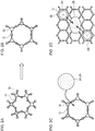
- Figs. 2A-2D are schematic diagrams illustrating a mechanism of formation of a phosphor of nanocomposite type.
- Silica has an amorphous structure having a basic skeleton in which SiO 4 tetrahedrons are joined by Si-O-Si bonds.
- the coupling angle of Si-O-Si is 145° ⁇ 10° ( Fig. 2A ).
- Silica exhibits a small coefficient of thermal expansion when heated to about 1000°C, but the coefficient of thermal expansion increases gradually beyond about 1000°C. This is because active hydrogen is produced from OH groups on the silica surface and severance and rearrangement of Si-O-Si bonds occur in selected portions of the silica.
- the coupling angle of Si-O-Si grows to 180° and a large gap is created in a network of SiO 4 joined together.
- the gap defines a pocket for positive ions 24 such as Ca 2+ and Eu 2+ , and negative ions 26 such as halogen, causing these ions to be incorporated into a network of SiO 4 joined together.
- ion crystal cores 28 ( Fig. 2D ).
- Production of ion crystal cores 28 is considered to set off crystallization of the silica in the matrix phase to produce cristobalites. It is inferred that the phosphor of nanocomposite type is produced in this way.
- the phosphor area according to the embodiment has a cristobalite structure produced by crystallization of portions of the silica embodying the matrix phase at least at the interface with the matrix phase. Accordingly, the phosphor contained in the fluorescent areas is stabilized.
- silica which is relatively stable, can be used as a base material of the matrix phase.
- a luminant 1 according to Example 1 is embodied by a quartz glass plate that contains CaI 2 :Eu 2+ as a fluorescent component.
- the glass surface was then cleaned with pure water to produce a matrix phase of a substrate shape.
- the fluorescent component is then prepared.
- base materials including CaI 2 , EuCl 3 , NH 4 I, and NH 4 F are mixed in a globe box of an N 2 atmosphere (molar ratio of 1:0.08:0.3:0.05) to produce a base mixture.
- the roughened surface of quartz glass described above is paved by 0.5 g of this base mixed powder.
- the substrate was then cleaned with hot pure water to wash away excess base materials and obtain a fluorescent plate (plate-shaped luminant 1).
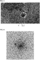
- Fig. 3 is a transmission electron microscope (TEM) image of the fluorescent plate according to Example 1.
- Fig. 4 shows an electron beam diffraction pattern in an area R of Fig. 3 .
- the results shown in Figs. 3 and 4 and other analysis revealed that portions of the quartz glass are crystallized and cristobalites are produced in the fluorescent plate according to Example 1.
- the CaI 2 :Eu monocrystal fluorescent component of ⁇ 60 nm is dispersed in the fluorescent plate. That the fluorescent component is comprised of monocrystals is clear from the electron beam diffraction pattern shown in Fig. 4 .
- the depth to which the CaI 2 :Eu monocrystals are dispersed is about 250 ⁇ m and the monocrystal fine particles are dispersed such that the particles are completely covered by the matrix phase.
- Fig. 5 shows an excitation spectrum and an emission spectrum of the fluorescent plate according to Example 1.
- the fluorescent plate according to Example 1 absorbs a near ultraviolet light of a wavelength around 400 nm.
- the fluorescent plate according to Example 1 emits a blue light having a peak wavelength around 465 nm by being excited by a near ultraviolet light having a peak wavelength of 400 nm.
- the luminant 2 according to Example 2 is embodied by alkaline-earth borosilicate glass that contains CdSe as a fluorescent component.
- the fluorescent component is then prepared.
- base materials including B 2 Se 3 , CdO, and NH 4 F are mixed in a globe box of an N 2 atmosphere (molar ratio of 1:3:0.1) to produce a base mixture.
- the etched surface of alkaline-earth borosilicate glass described above is paved by 0.5 g of this base mixed powder.
- a sapphire substrate is placed on the paved surface.
- the composite is heated at 550° for 10 minutes, and then the temperature is rapidly increased to 1000°C.
- the substrate was then cleaned with hot pure water to wash away excess base materials and obtain a fluorescent plate (plate-shaped luminant 2).
- the fluorescent plate according to Example 2 was revealed to be a luminant in which CdSe quantum dots of ⁇ 3 ⁇ 8 nm are dispersed inside a glass matrix phase.
- Fig. 6 shows an emission spectrum of the fluorescent plate according to Example 2.
- the fluorescent plate according to Example 2 is excited by a near ultraviolet light having a peak wavelength of 400 nm or smaller, and, as can be seen in the emission spectrum S3 shown in Fig. 6 , emits an orange light having a peak wavelength around 520 nm.
- a luminant 3 according to Example 3 is embodied by a quartz fiber that contains CaCl 2 :Eu 2+ as a fluorescent component.
- fiber-shaped quartz glass of ⁇ 200 ⁇ m and a length of 20 mm is first immersed in a 2N aqueous solution of NaOH and is subject to an ultrasonic treatment for 1 minute. The glass was then filtered and cleaned by pure water and was dried to produce a fiber-shaped matrix phase.
- the fluorescent component is then prepared.
- base materials including CaCl 2 , EuCl 3 , and NH 4 Cl are mixed in a globe box of an N 2 atmosphere (molar ratio of 1:0.10:0.4) to produce a base mixture.
- 1.0 g of this base mixed powder and 1 g of the quartz fiber described above are placed in a polypropylene pot and mixed by a rotary blender for 10 minutes.
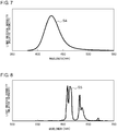
- Fig. 7 shows an emission spectrum of the fluorescent fiber according to Example 3.
- the fluorescent fiber according to Example 3 is excited by a near ultraviolet light having a peak wavelength of 380 nm or smaller, and, as can be seen in the emission spectrum S4 shown in Fig. 7 , emits a blue light having a peak wavelength around 425 nm.
- a luminant 4 according to Example 4 is embodied by glass fluoride that contains YF 3 :Eu 3+ as a fluorescent component.
- the fluorescent plate according to Example 4 is a luminant in which the YF 3 :Eu 3+ monocrystal fluorescent component of about ⁇ 20 nm is dispersed inside the glass matrix phase.
- Fig. 8 shows an emission spectrum of the fluorescent plate according to Example 4.
- the fluorescent plate according to Example 4 is excited by an ultraviolet light having a peak wavelength of 254 nm, and, as can be seen in the emission spectrum S5 shown in Fig. 8 , emits a red light having a peak wavelength around 609 nm.
- the luminant 5 according to Example 5 is embodied by phosphate glass that contains (Y,Ce,Tb)PO 4 as a fluorescent component.
- the fluorescent plate according to Example 5 is a luminant in which the (Y,Ce,Tb)PO 4 monocrystal fluorescent component of about ⁇ 30 nm is dispersed inside a glass matrix phase.
- Fig. 9 shows an emission spectrum of the fluorescent plate according to Example 5.
- the fluorescent plate according to Example 5 is excited by a near ultraviolet light having a peak wavelength of 350 nm or smaller, and, as can be seen in the emission spectrum S6 shown in Fig. 9 , emits a green light having a peak wavelength around 543 nm.
- a luminant 6 according to Example 6 is embodied by silica glass that contains CaS:Eu 2+ as a fluorescent component.
- the fluorescent component is then prepared.
- base materials including CaS:Eu(NO 3 ) 3 :NH 4 F are mixed in a globe box of an N 2 atmosphere (molar ratio of 10:0.5:0.1) to produce a base mixture.
- 0.5 g of this base mixed powder is mixed with 4.5 g of silica glass processed as described above in a globe box of a nitrogen atmosphere.
- the mixed powder is then put into an alumina crucible, and the temperature is increased to 1400°C.
- the resultant powder was then cleaned with dilute hydrochloric acid to wash away excess base materials and obtain a fluorescent plate (plate-shaped luminant 6).
- the fluorescent plate according to Example 6 is a luminant in which CaS:Eu 2+ of ⁇ 50 mm is dispersed inside a silica matrix phase.
- Fig. 10 shows an emission spectrum of the fluorescent plate according to Example 6.
- the fluorescent plate according to Example 6 is excited by a blue light having a peak wavelength of 450 nm, and, as can be seen in the emission spectrum S7 shown in Fig. 10 , emits a red light having a peak wavelength around 625 nm.
- a luminant 7 according to Example 7 is embodied by silica particles that contain CaI 2 :Eu 2+ as a fluorescent component.
- amorphous silica (SiO 2 ) particles of ⁇ 50 ⁇ m is first prepared.
- the fluorescent component is then prepared.
- base materials including CaI 2 , EuCl 3 , NH 4 I, and SiO 2 are mixed in a globe box of an N 2 atmosphere (molar ratio of 1:0.08:0.3:8) to produce a base mixture.
- the particles were then cleaned with hot pure water to wash away excess base materials and obtain fluorescent particles (the luminant 7 in a particle form).
- the fluorescent particles according to Example 7 emit a blue light having a peak wavelength around 465 nm by being excited by a near ultraviolet light having a peak wavelength of 400 nm.
- the fine particles may have an average particle diameter of about 1 ⁇ 100 nm, and, more preferably, about 2 ⁇ 80 nm, and, still more preferably, about 3 ⁇ 60 nm. In this way, desired light emission characteristics can be realized by a phosphor comprised of a smaller number of fine particles.
- the manufacturing method according to the embodiment includes a step of placing one or more compounds as base materials for the phosphor on the surface of a member embodying a matrix phase, and a step of heating the composite while the compounds are placed on the surface of the member. This can allow the compound embodying the phosphor to enter the matrix phase by a simple method.
- Nanocomposite production according to the invention solves the problem and is particularly useful for fluorescent components (Examples 1, 2, 3, 6, 7) that are excellent in fluorescence characteristics but poor in humidity resistance.
- Table 1 shows a result of a shelf test in which the phosphors are left for 24 hours at 85°C and 85%. In Table 1, it is defined the initial fluorescence intensity of each phosphor excited by an excitation wavelength of 365 nm to emit light is 100%.
- the sustention ratio listed in the table represents the percentage of fluorescence intensity of the phosphor excited by the same wavelength after the shelf test.
- the phosphors (luminants) according to Examples 1, 2, 3, 6, and 7 exhibited the sustention ratio of 98% or higher and showed no degradation.
- Table 1 Fluorescent component Sustention ratio Sustention rate of phosphor of same composition
- Example 1 CaI 2 :Eu 2+ 99% 0%
- Example 3 CaCl 2 :Eu 2+ 98% 0%
- Example 6 CaS:Eu 2+ 100% 8%
- the luminants according to the embodiment can be manufactured by using a variety of compounds of low humidity resistance that could not have been used in the related art, so long as they meet the initial performance required of the phosphor.
- Compounds that can be used in the phosphors according to the embodiment are exemplified by (1) ⁇ (5) listed below.
- Nanocomposite production allows the fluorescent component to be dispersed in the substrate of the matrix phase that is worked into a desired size and shape so that the flexibility of the shape is dramatically improved as compared with the related-art powder phosphor.
- Nanocomposite production significantly reduces the content rare-earth element embodying the light emission center necessary to obtain a desired fluorescence intensity.
- Table 2 compares the content of rare-earth elements in the luminants according to Examples 4 and 5 containing 4% of the fluorescent component with the content of rare-earth elements in the powder phosphor of the same composition. As shown in Table 2, inclusion of the monocrystal fine particle phosphor in the fluorescent area as in the case of the luminants according to the embodiment significantly reduces the rare-earth elements used.
- halides compound of a halogen (fluorine (F), chlorine (Cl), bromine (Br), iodine (I), etc.) and an element having a lower electronegativity
- chalcogenides compound of a Group-XVI element (oxygen (O), sulfur (S), selenium (Se), tellurium (Te), polonium (Po), etc.) and an element having a lower electronegativity
- chalcogenides compound of a Group-XVI element (oxygen (O), sulfur (S), selenium (Se), tellurium (Te), polonium (Po), etc.
- transition elements Group-III elements ⁇ Group-XII elements
- rare-earth elements or in compounds produced by doping transition elements with rare earths.
- these compounds can be turned into functional materials having a desired function at a room temperature, such as luminant materials, magnetic materials, thermoelectric materials, electromagnetic materials, and superconductive materials.
- These functional materials are available in a certain variety, leaving aside the consideration of use conditions and durability. Meanwhile, materials that can be put into actual use are limited, considering the resistance to external factors such as temperature, humidity, and light. For this reason, there is much room for improvement in the function and performance realized by materials that can be selected.
- the functional area exhibiting a desired function may not necessarily have resistance to an external environment and that a number of compounds that could not have been employed in respect of durability in the related art can be used in the functional area by ensuring that the functional area is not directly in contact with the environment.
- the nanocomposite according to an embodiment is produced by dispersing luminescent CaI 2 :Eu 2+ single nanocrystals in a semitransparent silica (SiO 2 ) matrix.
- the method of manufacturing a nanocomposite includes forming single nanocrystals in a crystalline silica matrix through a self-organizing process initiated by a simple solid-phase reaction.
- the nanocomposite phosphor according to an embodiment emits a strong cold blue light only from single nanocrystals and, regardless of the small Eu content, emits light with a high internal quantum efficiency (IQE) of 98%, which is higher than that of the related-art phosphors.
- IQE internal quantum efficiency
- the ratio of absorption is about 85%.
- the nanocomposite phosphor according to an embodiment has sufficiently practical durability because the CaI 2 :Eu emission site is embedded in the crystalline silica and the emission site is protected from the outside humidity by the crystalline silica.
- Figs. 11A-11D are schematic diagrams illustrating an exemplary mechanism of formation of a nanocomposite phosphor.
- base materials including amorphous SiO 2 particles 30, CaI 2 particles 32, EU 2 O 3 particles, and NH 4 I particles 36 are mixed.
- the base mixture is then heated to 1000°C (1273 K). During the heating, the base mixture undergoes the following two changes.
- Fig. 12 shows an absorption spectrum of the silica before and after the calcination, measured by a Fourier transform infrared spectrophotometer (FTIR). As show in Fig.
- the melted CaI 2 becomes fluid on the surfaces of the activated SiO 2 particles 30 ( Fig. 11C ).
- the SiO 2 particles 30 are crystallized due to the flux effect, beginning at the particle surface. During the crystallization, some SiO 2 particles 30 are bonded to form a single SiO 2 grain aggregate 40 ( Fig. 11D ).
- the particle diameter of (CaI 2 /SiO 2 ) :Eu 2+ particles becomes larger than the particle diameter of the SiO 2 particles 30 in the starting base materials.
- Fig. 13 shows a particle diameter distribution of SiO 2 particles occurring before the mixture (line L4), after the mixture (line L5), and after the calcination (line L6). As shown in Fig. 13 , the average particle diameter of SiO 2 particles become smaller when the materials are ground and mixed than before the mixture but, after the calcination, become larger than before the mixture.
- Fig. 14A is a schematic view showing CaI 2 :Eu 2+ single nanocrystals produced inside the calcinated SiO 2 grain aggregate
- Fig. 14B shows an electron beam diffraction pattern of the crystal area outward of the grain aggregate
- Fig. 14C shows an electron beam diffraction pattern of the amorphous area toward the center of the grain aggregate.
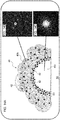
- the melted CaI 2 is localized between an amorphous area 40a and a crystal area 40b in the bonded SiO 2 grain aggregate 40.
- the melted CaI 2 is solidified in the SiO 2 particles in a subsequent temperature lowering step of calcination, thereby producing CaI 2 :Eu 2+ single nanocrystals 42.
- a nanocomposite phosphor 50 is formed.
- the practical durability of the nanocomposite phosphor comprised of (CaI 2 /SiO 2 ) :Eu 2+ is secured because CaI 2 :Eu 2+ , which has a poor resistance to humidity, is protected from the ambient air by the crystalline silica.
- the electron beam diffraction pattern shown in Fig. 14C reveals that the inside of the ring-shaped area R1, i.e., the homogeneous core, is amorphous.
- the electron beam diffraction pattern shown in Fig. 14B reveals that the outside of the ring-shaped area R1, i.e., the outer matrix portion is a tetragonal SiO 2 crystal layer.
- the majority of the single nanocrystals 42 comprised of CaI 2 :Eu 2+ is formed at the boundary between the amorphous area 40a of SiO 2 particles and the crystal area 40b.
- amorphous SiO 2 used as the starting base material, the temperature of 1350°C or higher is necessary. In other words, crystallization of amorphous SiO 2 should not occur at the calcination temperature 1000°C. As shown in Fig 14B , however, SiO 2 is crystallized in the outward portion of the SiO 2 grain aggregated 40. In other words, this shows that only the area impregnated by CaI 2 is crystallized at the calcination temperature 1000°C.
- Example 1 Self-organization of single nanocrystals was also confirmed by another method (Example 1).
- an amorphous SiO 2 glass plate having a roughened surface is used as a base material instead of amorphous SiO 2 powder.
- a base material including CaI 2 was placed on the roughened surface.
- the composite was calcinated to produce a nanocomposite fluorescent plate.
- the nanocomposite fluorescent plate thus manufactured emits a blue light by being excited by ultraviolet light of 405 nm. It was also confirmed that, by impregnating the silica glass whose surface is roughened with the melted CaI 2 flux, the top surface (roughened surface) of the silica glass becomes semitransparent and emits a blue light. Meanwhile, the bottom surface maintains transparency. As described above, it is reasoned that impregnation with the CaI 2 flux is linked to the formation of the nanocomposite phosphor.
- a nanocomposite phosphor comprised of (CaI 2 /SiO 2 ) :Eu 2+ can be synthesized through a solid-phase reaction at a calcination temperature of 1000°C, which is remarkably lower than the crystallization temperature of SiO 2 . Further, the nanocomposite phosphor is structured such that CaI 2 :Eu 2+ single nanocrystals are embedded in the crystalline silica.
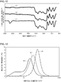
- Fig. 15 shows an excitation spectrum and an emission spectrum of the nanocomposite phosphor.
- the excitation spectrum S8 and the emission spectrum S9 shown in Fig. 15 are those of the nanocomposite phosphor comprised of (CaI 2 /SiO 2 ) :Eu 2+ .
- the emission spectrum of the nanocomposite phosphor according an embodiment has a peak wavelength of 471 nm and a half width 32. 4 nm.
- the excitation spectrum S10 and the emission spectrum S11 shown in Fig. 15 are those of a BaMgAl 10 O 17 :Eu 2+ (BAM:E u 2+ ) phosphor that is widely used as a blue light phosphor.
- BAM:E u 2+ BaMgAl 10 O 17 :Eu 2+
- the nanocomposite phosphor excited by 400 nm exhibits a peak light emission intensity about 2.7 times that of the BAM:Eu 2+ phosphor.
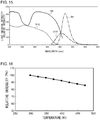
- Fig. 16 shows the temperature characteristics of the nanocomposite phosphor.
- the intensity is normalized by defining the luminescence intensity at a room temperature (30°C) to be 100%.
- the nanocomposite phosphor maintains 90% or higher luminescence intensity from the room temperature to 150°C.
- Fig. 17 shows a result of a life test of the nanocomposite phosphor.
- the life test was conducted at a temperature 85°C and a humidity 85%.
- the luminescence intensity was measured on an hourly basis as the nanocomposite phosphor was allowed to emit light continuously for 2000 hours.
- the result shows that variation in the luminescence intensity after 2000 hours is 2% or less, showing that the phosphor exhibits very stable light emission characteristics in a high temperature and high humidity environment.
- the (CaI 2 /SiO 2 ) :Eu 2+ emission site is formed by an iodide which has a poor resistance to humidity
- the light emission performance and the practical level of reliability (durability) can be secured by embedding the emission site in the SiO 2 semitransparent matrix. Therefore, nanocomposite production is expected to expand the applications of substances with a low resistance to humidity such as halides and chalcogenides beyond the phosphor.
- Calcination is performed at a temperature that melts the functional material comprised of a halide/chalcogenide compound and does not crystallize amorphous silica that embodies the matrix member.
- the halide/chalcogenide compound functions as a flux to crystallize the amorphous silica at a temperature lower than the crystallization temperature.
- the halide/chalcogenide compound will be localized near the boundary between the crystalline substance and the amorphous substance.
- the halide/chalcogenide compound turned into a liquid phase is cooled and solidified in the silica crystal and is precipitated as 10 nm ⁇ 100 ⁇ m crystals, thereby forming a nanocomposite.
- the suitable range of calcination temperature is 1000 ⁇ 1250°C, which is lower than the amorphous silica crystallization temperature of 1300 ⁇ 1350°C.
- the calcination atmosphere and the deoxidation atmosphere are filled with a gas such as nitrogen, argon, and hydrogen-containing nitrogen.
- the halide/chalcogenide compound having a melting point of 1200°C or lower is suitable. Generally, no reactions are induced between a halide/chalcogenide compound and silica. A specific description will be given with reference to examples.
- the nanocomposite according to Example 8 is embodied by a crystalline silica matrix that contains CaI 2 :Eu 2+ as a fluorescent component.
- amorphous silica (average particle diameter 30 ⁇ m) having a crystallization temperature 1350°C, CaI 2 (melting point 779°C), and EuI 3 were precisely weighted such that molar ratio thereof is 6/0.8/0.1 and were put into an alumina mortar in an Ar gas atmosphere to ground and mix the materials.
- Fig. 18 shows an X-ray diffraction pattern of the nanocomposite according to Example 8.
- An analysis of the peaks shown in Fig. 18 revealed that the nanocomposite according to Example 8 is a powder in which ⁇ -cristobalites, which form a high-temperature crystal phase of silica, represent the main phase. Irradiation of the nanocomposite with an ultraviolet light having a peak wavelength of 400 nm resulted in observation of a blue light having a peak wavelength of 461 nm.
- Fig. 19 shows a cross-sectional SEM image of the nanocomposite according to Example 8.
- the nanocomposite was comprised of a matrix portion and white dot portions.
- a composition analysis of the respective portions by means of an energy dispersive X-ray (EDX) spectrometer attached to an SEM showed that the matrix portion is comprised of SiO 2 , and the content of Ca and I in the white dot portions is relatively large.
- EDX energy dispersive X-ray
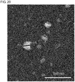
- Fig. 20 shows a cross-sectional STEM image of the nanocomposite according to Example 8.
- Fig. 21 shows a result of STEM-EDX composition analysis along a line A-A of Fig. 20 .
- the diameter of the white dot portions is about 50 nm.
- the STEM-EDX line analysis showed that the content of Ca, I, and Eu in the white dot portions is larger than in surrounding areas.
- Fig. 22 shows an electron beam diffraction pattern of the white dot portions shown in Fig. 20 .
- Indexing shown in Fig. 22 is consistent in the case that the white dot portions are CaI 2 monocrystals so that it can be estimated that the white dot portions are CaI 2 single nanocrystals. It was thus found that the particles shown in Fig. 19 represent a nanocomposite member in which heterogenous crystals form a sea-island structure.
- the nanocomposite according to Example 9 is embodied by a crystalline silica matrix that contains SrCl 2 :Eu 2+ as a fluorescent component.
- amorphous silica (average particle diameter 30 ⁇ m) having a crystallization temperature 1350°C, SrCl 2 (melting point 874°C), and EuCl 3 were precisely weighted such that molar ratio thereof is 6/0.8/0.1 and were put into an alumina mortar in an Ar gas atmosphere to ground and mix the materials.
- Fig. 23 shows an X-ray diffraction pattern of the nanocomposite according to Example 9.
- An analysis of the peaks shown in Fig. 23 revealed that the nanocomposite according to Example 9 is a powder in which ⁇ -cristobalites and tridymites, which form a high-temperature crystal phase of silica, represent the main phase. Irradiation of the nanocomposite with an ultraviolet light having a peak wavelength of 365 nm resulted in observation of an ultraviolet light having a peak wavelength of 405 nm.
- Fig. 24 shows an excitation spectrum and an emission spectrum of the nanocomposite phosphor according to Example 9.
- the nanocomposite according to Example 10 is embodied by a crystalline silica matrix that contains SrI 2 :Eu 2+ as a fluorescent component.
- amorphous silica (average particle diameter 30 ⁇ m) having a crystallization temperature 1350°C, SrI 2 (melting point 402°C), and EuI 3 were first precisely weighted such that molar ratio thereof is 6/0.8/0.1 and were put into an alumina mortar in an Ar gas atmosphere to ground and mix the materials.
- Fig. 25 shows an X-ray diffraction pattern of the nanocomposite according to Example 10.
- An analysis of the peaks shown in Fig. 25 revealed that the nanocomposite according to Example 10 is a powder in which ⁇ -cristobalites, which form a high-temperature crystal phase of silica, represent the main phase. Irradiation of the nanocomposite with an ultraviolet light having a peak wavelength of 365 nm resulted in observation of a blue light having a peak wavelength of 430 nm.
- Fig. 26 shows an excitation spectrum and an emission spectrum of the nanocomposite according to Example 10.
- the nanocomposite according to Example 11 is embodied by a crystalline silica matrix that contains SrBr 2 :Eu 2+ as a fluorescent component.
- amorphous silica (average particle diameter 30 ⁇ m) having a crystallization temperature 1350°C, SrBr 2 (melting point 643°C), and EuBr 3 were precisely weighted such that molar ratio thereof is 6/0.8/0.1 and were put into an alumina mortar in an Ar gas atmosphere to ground and mix the materials.
- Fig. 27 shows an X-ray diffraction pattern of the nanocomposite according to Example 11.
- An analysis of the peaks shown in Fig. 27 revealed that the nanocomposite according to Example 11 is a powder in which ⁇ -cristobalites and tridymites, which form a high-temperature crystal phase of silica, represent the main phase.
- Irradiation of the nanocomposite with an ultraviolet light having a peak wavelength of 335 nm resulted in observation of a bluish-purple light having a peak wavelength of 410 nm.
- Fig. 28 shows an excitation spectrum and an emission spectrum of the nanocomposite according to Example 11.
- the nanocomposite according to Example 12 is embodied by a crystalline silica matrix that contains MgCl 2 :Eu 2+ as a fluorescent component.
- amorphous silica (average particle diameter 30 ⁇ m) having a crystallization temperature 1350°C, MgCl 2 (melting point 714°C), and EuCl 3 are first precisely weighted such that molar ratio thereof is 6/0.8/0.1 and are put into an alumina mortar in an Ar gas atmosphere to ground and mix the materials.
- Fig. 29 shows an X-ray diffraction pattern of the nanocomposite according to Example 12.
- An analysis of the peaks shown in Fig. 29 revealed that the nanocomposite according to Example 12 is a powder in which ⁇ -cristobalites, which form a high-temperature crystal phase of silica, represent the main phase.
- Irradiation of the nanocomposite with an ultraviolet light having a peak wavelength of 340 nm resulted in observation of a blue light having a peak wavelength at 410 nm and 440 nm.
- Fig. 30 shows an excitation spectrum and an emission spectrum of the nanocomposite according to Example 12.
- the nanocomposite according to Example 13 is embodied by a crystalline silica matrix that contains monocrystal fine particles as a magnetic component.
- amorphous silica (average particle diameter 30 ⁇ m) having a crystallization temperature 1350°C, SnS (melting point 880°C), and CoS (melting point 1100°C) were first precisely weighted such that molar ratio thereof is 6/0.8/0.2 and were put into an alumina mortar in an Ar gas atmosphere to ground and mix the materials.
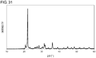
- Fig. 31 shows an X-ray diffraction pattern of the nanocomposite according to Example 13.
- An analysis of the peaks shown in Fig. 31 revealed that the nanocomposite according to Example 13 is a powder in which ⁇ -cristobalites, which form a high-temperature crystal phase of silica, represent the main phase. Further, the nanocomposite particles thus obtained were magnetic and attracted by a magnet. In other words, it was demonstrated that single nanocrystals dispersed in the nanocomposite according to the embodiment function as a magnetic body or another functional area as well as a phosphor.
- Nanopolycrystals may be dispersed in the matrix phase instead of single nanocrystals so long as the compound can exhibit the function.
- the present invention relates to a nanocomposite, which can be used as a functional member such as a luminant and a magnetic body.
Landscapes
- Chemical & Material Sciences (AREA)
- Engineering & Computer Science (AREA)
- Materials Engineering (AREA)
- Organic Chemistry (AREA)
- Inorganic Chemistry (AREA)
- Chemical Kinetics & Catalysis (AREA)
- Life Sciences & Earth Sciences (AREA)
- General Chemical & Material Sciences (AREA)
- Geochemistry & Mineralogy (AREA)
- Ceramic Engineering (AREA)
- Dispersion Chemistry (AREA)
- Crystallography & Structural Chemistry (AREA)
- Luminescent Compositions (AREA)
- Glass Compositions (AREA)
Applications Claiming Priority (3)
| Application Number | Priority Date | Filing Date | Title |
|---|---|---|---|
| JP2016081918 | 2016-04-15 | ||
| JP2017062297 | 2017-03-28 | ||
| PCT/JP2017/014939 WO2017179609A1 (fr) | 2016-04-15 | 2017-04-12 | Nanocomposite et procédé de production de nanocomposite |
Publications (2)
| Publication Number | Publication Date |
|---|---|
| EP3444231A1 true EP3444231A1 (fr) | 2019-02-20 |
| EP3444231A4 EP3444231A4 (fr) | 2019-11-13 |
Family
ID=60042175
Family Applications (1)
| Application Number | Title | Priority Date | Filing Date |
|---|---|---|---|
| EP17782422.4A Withdrawn EP3444231A4 (fr) | 2016-04-15 | 2017-04-12 | Nanocomposite et procédé de production de nanocomposite |
Country Status (5)
| Country | Link |
|---|---|
| US (1) | US10807903B2 (fr) |
| EP (1) | EP3444231A4 (fr) |
| JP (1) | JP6941600B2 (fr) |
| CN (1) | CN109071324A (fr) |
| WO (1) | WO2017179609A1 (fr) |
Families Citing this family (5)
| Publication number | Priority date | Publication date | Assignee | Title |
|---|---|---|---|---|
| JP6985882B2 (ja) | 2017-10-13 | 2021-12-22 | 株式会社小糸製作所 | シンチレータ材料および放射線検出器 |
| JP6942687B2 (ja) * | 2018-11-07 | 2021-09-29 | 古河電気工業株式会社 | 医療器具及び医療器具確認システム |
| CN110459670B (zh) * | 2019-08-06 | 2021-08-10 | 武汉理工大学 | 基于非晶材料原位制备磁性纳米复合热电材料的方法 |
| CN112859447B (zh) * | 2021-03-10 | 2023-04-11 | 京东方科技集团股份有限公司 | 光学玻璃及其制备方法、背光模组和显示模组 |
| US12466997B2 (en) | 2021-03-11 | 2025-11-11 | Koito Manufacturing Co., Ltd. | Scintillator material, radiation detector, and method for producing scintillator material |
Family Cites Families (25)
| Publication number | Priority date | Publication date | Assignee | Title |
|---|---|---|---|---|
| US3527711A (en) * | 1963-04-16 | 1970-09-08 | Owens Illinois Inc | Process for preparing rare earth doped luminescent silica glass |
| US3522189A (en) * | 1966-10-17 | 1970-07-28 | Owens Illinois Inc | Luminescent material of terbium doped cristobalite |
| JP3729047B2 (ja) | 1996-12-27 | 2005-12-21 | 日亜化学工業株式会社 | 発光ダイオード |
| JP4433631B2 (ja) * | 2000-04-05 | 2010-03-17 | 松本油脂製薬株式会社 | 希土類鉄ガーネットナノクリスタルを分散させたガラス媒体を作成する方法 |
| US6774560B1 (en) * | 2000-09-19 | 2004-08-10 | The Regents Of The University Of California | Material system for tailorable white light emission and method for making thereof |
| US7078071B2 (en) * | 2000-10-05 | 2006-07-18 | Matsumoto Yushi-Seiyaku Co., Ltd. | Glass composite including dispersed rare earth iron garnet nanoparticles |
| JP4191937B2 (ja) * | 2002-02-15 | 2008-12-03 | 株式会社日立製作所 | 白色光源及びそれを用いた画像表示装置 |
| EP1566367B1 (fr) * | 2002-11-29 | 2015-01-07 | Japan Science and Technology Agency | Verre luminescent |
| US7999455B2 (en) * | 2006-11-13 | 2011-08-16 | Research Triangle Institute | Luminescent device including nanofibers and light stimulable particles disposed on a surface of or at least partially within the nanofibers |
| JP2006103991A (ja) * | 2004-10-01 | 2006-04-20 | Okamoto Glass Co Ltd | 半導体微粒子分散ガラス蛍光体及びこれを用いた光学機器 |
| JP2006229134A (ja) * | 2005-02-21 | 2006-08-31 | Toyota Gakuen | 光増幅媒体とその製造方法および光増幅器 |
| DE102006013055A1 (de) * | 2006-03-22 | 2007-09-27 | Merck Patent Gmbh | Gasphasen-Infiltrierung von Leuchtstoffen in das Porensystem von inversen Opalen |
| KR101278768B1 (ko) * | 2006-04-13 | 2013-06-25 | 삼성전자주식회사 | 전계 발광소자 및 이를 포함하는 전자장치 |
| JP5371359B2 (ja) * | 2007-12-27 | 2013-12-18 | 豊田合成株式会社 | 蛍光体含有ガラス板及び発光装置の製造方法 |
| JP2008208380A (ja) | 2008-05-26 | 2008-09-11 | Nippon Electric Glass Co Ltd | 発光色変換部材 |
| US8426871B2 (en) * | 2009-06-19 | 2013-04-23 | Honeywell International Inc. | Phosphor converting IR LEDs |
| JP6010051B2 (ja) * | 2011-02-03 | 2016-10-19 | コーニンクレッカ フィリップス エヌ ヴェKoninklijke Philips N.V. | シングル又はマルチエネルギー縦型感放射線検出器アレイおよび放射線検出方法 |
| DE102011078663A1 (de) * | 2011-07-05 | 2013-01-10 | Osram Ag | Verfahren zur Herstellung eines Konversionselements und Konversionselement |
| WO2014119783A1 (fr) * | 2013-02-04 | 2014-08-07 | ウシオ電機株式会社 | Dispositif de source de lumière fluorescente |
| CN105916962B (zh) * | 2013-11-19 | 2019-02-05 | 三星电子株式会社 | 发光颗粒、包含其的材料和产品、以及方法 |
| JP6489543B2 (ja) * | 2014-05-28 | 2019-03-27 | シャープ株式会社 | 波長変換部材、発光装置、および波長変換部材の製造方法 |
| JP2016143742A (ja) * | 2015-01-30 | 2016-08-08 | シャープ株式会社 | 波長変換部材、発光装置、および波長変換部材の製造方法 |
| KR20180075434A (ko) * | 2015-10-27 | 2018-07-04 | 니폰 덴키 가라스 가부시키가이샤 | 파장 변환 부재의 제조 방법 |
| CN105481254B (zh) * | 2015-11-27 | 2018-03-06 | 南京邮电大学 | 具有转光和光温传感双功能的透明玻璃陶瓷及其制备方法 |
| JP6985882B2 (ja) * | 2017-10-13 | 2021-12-22 | 株式会社小糸製作所 | シンチレータ材料および放射線検出器 |
-
2017
- 2017-04-12 EP EP17782422.4A patent/EP3444231A4/fr not_active Withdrawn
- 2017-04-12 CN CN201780023761.0A patent/CN109071324A/zh active Pending
- 2017-04-12 WO PCT/JP2017/014939 patent/WO2017179609A1/fr not_active Ceased
- 2017-04-12 JP JP2018512040A patent/JP6941600B2/ja active Active
-
2018
- 2018-10-14 US US16/159,683 patent/US10807903B2/en not_active Expired - Fee Related
Also Published As
| Publication number | Publication date |
|---|---|
| JP6941600B2 (ja) | 2021-09-29 |
| JPWO2017179609A1 (ja) | 2019-02-21 |
| US10807903B2 (en) | 2020-10-20 |
| US20190047903A1 (en) | 2019-02-14 |
| CN109071324A (zh) | 2018-12-21 |
| EP3444231A4 (fr) | 2019-11-13 |
| WO2017179609A1 (fr) | 2017-10-19 |
Similar Documents
| Publication | Publication Date | Title |
|---|---|---|
| US10807903B2 (en) | Nanocomposites and method of manufacturing nanocomposites | |
| DE112014004638B4 (de) | Leuchtstoff und Verfahren zum Herstellen eines Leuchtstoffs | |
| JP5545665B2 (ja) | 蛍光体の製造方法 | |
| Wang et al. | Structural and luminescent properties of red-emitting Eu 3+-doped ternary rare earth antimonates R 3 SbO 7 (R= La, Gd, Y) | |
| US8048338B2 (en) | Phosphor, phosphor sheet, and manufacturing method therefore, and light emission device using the phosphor | |
| US10233388B2 (en) | Lighting device with a first phosphor and filter particles | |
| Kim et al. | Luminescent properties of rare earth fully activated apatites, LiRE9 (SiO4) 6O2 (RE= Ce, Eu, and Tb): site selective crystal field effect | |
| JP5041191B2 (ja) | 蛍光体粒子の製造方法 | |
| Mahalingam et al. | Facile hydrothermal synthesis and pulsed laser deposition of Ca 0.5 Y 1− x (WO 4) 2: x Eu 3+ phosphors: investigations on the luminescence, Judd–Ofelt analysis and charge compensation mechanism | |
| TW200831642A (en) | Phosphor element comprising ruby for white or colour-on-demand LEDs | |
| KR20160132959A (ko) | 고체-상태 조명을 위한 슈퍼사면체 인광체 | |
| Lei et al. | Morphology-controlled synthesis, physical characterization, and photoluminescence of novel self-assembled pomponlike white light phosphor: Eu3+-doped sodium gadolinium tungstate | |
| Cui et al. | Highly modified spontaneous emission in NaY (MoO 4) 2: Yb 3+/Er 3+ inverse opal photonic crystals | |
| CN118165723A (zh) | 一种钙钛矿纳米晶荧光材料及其制备方法和应用 | |
| Sheoran et al. | Novel synthesis and Optical investigation of trivalent Europium doped MGd2Si3O10 (M= Mg2+, Ca2+, Sr2+ and Ba2+) nanophosphors for full-color displays | |
| Fang et al. | Hydrothermal synthesis of uniform CdWO4: Eu3+ microrods as single component for UV-based WLEDs | |
| Liu et al. | ZnWO 4/ZnWO 4: Eu 3+ inverse opal photonic crystal scintillator: efficient phosphors in radiation detection | |
| Kumari et al. | Defects in rare-earth-doped inorganic materials | |
| US10174245B2 (en) | Method for producing a luminescent material, luminescent material and optoelectronic component | |
| Bawanthade et al. | Synthesis and study of optical properties of Dy3+ doped yellow emitting fluoroapatite for white-LED applications | |
| Ovalle et al. | Concentration and crystallite size dependence of the photoluminescence in YAG: Ce3+ nanophosphor | |
| CN121986148A (en) | Method for treating luminescent nanoparticles | |
| KR101505431B1 (ko) | 시드를 이용한 옥시오소실리케이트 형광체 제조방법 | |
| CN101253252A (zh) | 蓄光材料及其制造方法以及蓄光显示元件 | |
| Hasabeldaim | Luminescence properties of ZnO and ZnO: Eu³⁺ nanostructures and thin films |
Legal Events
| Date | Code | Title | Description |
|---|---|---|---|
| STAA | Information on the status of an ep patent application or granted ep patent |
Free format text: STATUS: THE INTERNATIONAL PUBLICATION HAS BEEN MADE |
|
| PUAI | Public reference made under article 153(3) epc to a published international application that has entered the european phase |
Free format text: ORIGINAL CODE: 0009012 |
|
| STAA | Information on the status of an ep patent application or granted ep patent |
Free format text: STATUS: REQUEST FOR EXAMINATION WAS MADE |
|
| 17P | Request for examination filed |
Effective date: 20181012 |
|
| AK | Designated contracting states |
Kind code of ref document: A1 Designated state(s): AL AT BE BG CH CY CZ DE DK EE ES FI FR GB GR HR HU IE IS IT LI LT LU LV MC MK MT NL NO PL PT RO RS SE SI SK SM TR |
|
| AX | Request for extension of the european patent |
Extension state: BA ME |
|
| DAV | Request for validation of the european patent (deleted) | ||
| DAX | Request for extension of the european patent (deleted) | ||
| A4 | Supplementary search report drawn up and despatched |
Effective date: 20191016 |
|
| RIC1 | Information provided on ipc code assigned before grant |
Ipc: C09K 11/77 20060101ALI20191009BHEP Ipc: C03C 21/00 20060101ALI20191009BHEP Ipc: C09K 11/56 20060101ALI20191009BHEP Ipc: C09K 11/02 20060101AFI20191009BHEP Ipc: C03C 14/00 20060101ALI20191009BHEP Ipc: C09K 11/88 20060101ALI20191009BHEP Ipc: C03C 10/00 20060101ALI20191009BHEP |
|
| STAA | Information on the status of an ep patent application or granted ep patent |
Free format text: STATUS: EXAMINATION IS IN PROGRESS |
|
| 17Q | First examination report despatched |
Effective date: 20200715 |
|
| STAA | Information on the status of an ep patent application or granted ep patent |
Free format text: STATUS: THE APPLICATION IS DEEMED TO BE WITHDRAWN |
|
| 18D | Application deemed to be withdrawn |
Effective date: 20211103 |