EP3444433A1 - Procédé de détermination de l'usure d'une tige d'un dispositif de forage de puits - Google Patents
Procédé de détermination de l'usure d'une tige d'un dispositif de forage de puits Download PDFInfo
- Publication number
- EP3444433A1 EP3444433A1 EP18179478.5A EP18179478A EP3444433A1 EP 3444433 A1 EP3444433 A1 EP 3444433A1 EP 18179478 A EP18179478 A EP 18179478A EP 3444433 A1 EP3444433 A1 EP 3444433A1
- Authority
- EP
- European Patent Office
- Prior art keywords
- linkage
- rod
- section
- load
- erdbohrvorrichtung
- Prior art date
- Legal status (The legal status is an assumption and is not a legal conclusion. Google has not performed a legal analysis and makes no representation as to the accuracy of the status listed.)
- Granted
Links
Images

Classifications
-
- E—FIXED CONSTRUCTIONS
- E21—EARTH OR ROCK DRILLING; MINING
- E21B—EARTH OR ROCK DRILLING; OBTAINING OIL, GAS, WATER, SOLUBLE OR MELTABLE MATERIALS OR A SLURRY OF MINERALS FROM WELLS
- E21B47/00—Survey of boreholes or wells
- E21B47/007—Measuring stresses in a pipe string or casing
-
- E—FIXED CONSTRUCTIONS
- E21—EARTH OR ROCK DRILLING; MINING
- E21B—EARTH OR ROCK DRILLING; OBTAINING OIL, GAS, WATER, SOLUBLE OR MELTABLE MATERIALS OR A SLURRY OF MINERALS FROM WELLS
- E21B47/00—Survey of boreholes or wells
- E21B47/01—Devices for supporting measuring instruments on drill bits, pipes, rods or wirelines; Protecting measuring instruments in boreholes against heat, shock, pressure or the like
-
- E—FIXED CONSTRUCTIONS
- E21—EARTH OR ROCK DRILLING; MINING
- E21B—EARTH OR ROCK DRILLING; OBTAINING OIL, GAS, WATER, SOLUBLE OR MELTABLE MATERIALS OR A SLURRY OF MINERALS FROM WELLS
- E21B47/00—Survey of boreholes or wells
- E21B47/01—Devices for supporting measuring instruments on drill bits, pipes, rods or wirelines; Protecting measuring instruments in boreholes against heat, shock, pressure or the like
- E21B47/017—Protecting measuring instruments
Definitions
- the invention relates to a method for determining a wear of a linkage of a Erdbohrvortechnik and a Erdbohrvortechnik with a linkage section. Furthermore, the invention relates to a use in a Erdbohrvortechnik for determining a wear of a linkage of the Erdbohrvorraum.
- Ground boring devices usually comprise a drive device and a linkage connected thereto, on which a drill head, which can be designed as a tool, can be attached.
- the drill head may be a widening head or tube retracting adapter.
- the driving forces of the drive device are transmitted to the drill head, whereby this is driven in the soil.
- compressive forces are applied to the drill head, so that it is pushed by the soil moving.
- boring by means of the auger also includes transmission of tensile forces to the linkage and the bit.
- the linkage of a Erdbohrvorraum regularly consists of a plurality of interconnected rod sections, which are successively interconnected (in the sliding operation) or separated from each other (in the pulling operation) according to the propulsion of the drill head in the ground.
- a connection between the rod sections can be done for example via screw or via plug-in couplings. Mixed connections of screw connections and plug-in couplings are possible.
- linear drives When transferring drive forces to the drill head by means of the linkage, almost exclusively linear drives are used, which transfer the drive forces or drive movements step by step to the linkage, ie with a load stroke in which the linkage is connected to the linear drive, and one idle stroke, in which the connection between the linear drive and the linkage is released.
- Conventional linear drives for Erdbohrvorraumen work with hydraulic cylinders as a drive source, by means of which high forces can be applied at relatively compact dimensions.
- linear drives with rack drives are known.
- the present invention seeks to increase the reliability of a Erdbohrvortechnische and / or to improve lifetime calculations of a linkage Erdbohrvortechnisch.
- the essence of the invention provides to detect bending loads of the linkage in order to improve a service life calculation and / or increase the reliability of a Erdbohrvorraum, the load is not determined in particular on the drive device, but in the well bore itself, by a course of the well bore , In particular, a curved portion of the bore, can be detected.
- a method for determining a wear of a linkage of an earth boring device therefore provides that a bending load of the linkage is detected in order to perform a service life calculation.
- a load is also determined essentially in addition to the drive device and a load in the well bore itself is detected.
- the load can be recorded within the borehole and taken into account for the service life calculation.
- the prevailing view that the rod sections are exposed exclusively to the load by the drive device or alone the load on the drive device is determined, has been supplemented according to the invention.
- linkage in the sense of the description includes not only rigid, individual with each other directly or indirectly connected rod sections having linkage, but in particular all the power transmission elements that can be used in a Erdbohrvorraum.
- linkage should not be understood to mean only the power transmission element which is disposed between the drive device of the earth boring device and the drill head, but basically all components of a drill string, i. all moving in the ground components, such a Erdbohrvortechnisch that are exposed to a load applied by the drive device forces and / or moments.
- linkage and the drill head can be understood as part of the drill string.
- the term "drive device” in the sense of the description comprises a drive by means of which the drive forces or drive movements are transmitted to the linkage or the drill string.
- the drive device can be designed as a linear drive.
- the drive device can also be configured as a rack drive.
- the drive device may comprise hydraulic cylinders as a drive source.
- the bending load of the linkage is measured by means of a linkage section, on which at least one strain sensor is present. It has been recognized that load detection is required independent of the auger drive mechanism, but this loading need not necessarily be performed by a metering operation on each linkage or linkage, but rather on one or more linkage sections in the drillstring or Linkage are arranged, and which can be assigned to the rod sections.
- machine data of the drive device can be used, from which at least one further information can be derived from the following machine data in order to carry out the service life calculation: torsion, tensile load, thrust load and rotational speed. From the machine data of the drive device then the torsional load, tensile / compressive load and / or speed of the individual rod sections can be determined.
- the bending load is detected by means of a strain gauge, a fiber Bragg grating sensor or the like. This makes it possible to use robust and proven sensors or detection elements that can be used even under the harsh conditions in the ground.
- the service life calculation is assigned to individual rod sections of the linkage. This makes it possible that not only a general statement about the rod sections of the boom in the ground is possible, but the load can be specified for each individual boom. It can be taken into account how long and at which position the linkage is located in the linkage. With regard to the bending load, it can thus be taken into account which rod section was subjected to a bending load or whether, for example, a rod section did not (yet) pass through a curved area of the bore hole. Depending on the position of the linkage in the linkage, the bending load can be taken into account.
- the method described is thus particularly suitable for determining the wear of a linkage comprising a plurality of interconnected rod sections.
- the individual loads of each or all of the rod sections are measured and, for this purpose, individual service life calculations are carried out. This in turn can significantly increase the accuracy of the lifetime calculations performed.
- the individual rod sections differ depending on the time at which they are incorporated into the linkage be charged for a long time.
- the individual rod sections are also used in a variety of operations, which usually can not be tracked, which linkage used in which work and how long he was burdened.
- the values for the individual rod sections are preferably stored separately, wherein this can be particularly preferably carried out in a memory element which is connected to the respective rod section itself.
- a complex data management is eliminated if the different rod sections for different work projects are mixed and used at different construction sites.
- the term "memory element" in the sense of the invention relates to any data memory or a storage medium which can be described and / or read in particular electronically.
- the memory element may store information based on electronic semiconductor devices or other devices.
- the memory element may in particular be a non-volatile memory. Contactless reading and / or writing of data to the memory element is preferred.
- a memory element may preferably be an RFID chip, which usually has an antenna, an analog circuit and a digital circuit and a non-volatile memory.
- the RFID chip may be a passive, active or semi-active RFID chip.
- the transmission of the measured load or of the individual service life calculations of a load case may preferably be performed by the drive device (a device integrated in the drive device) or by a device adjacent to the drive device (an additional device which, for example, at least (part) tasks of the service life calculation or carry out (part) tasks that can be performed in this context, for example, as a module to be purchased) are transmitted to the individual memory elements.
- a transmission device can preferably be provided on the device side (integrated with or into the drive device or separately therefrom) which serves to transmit the measured loads and / or the results of the service life calculations to the storage elements of the rod sections.
- the transmission device is preferably arranged on the drive device or integrated in or on it.
- the transmission device can also be added separately to the drive device, for example, the drive device can be supplemented or upgraded to the possibility of a lifetime calculation.
- the transmission of the measured load or the individual life calculations of a load case in a loaded on train linkage comprising a plurality of interconnected rod sections, take place when the linkage is gradually pulled by the drive device through a hole in the ground, said individual rod sections are successively pulled out of the earth hole and released from the remainder of the linkage by carrying out the loads or the results of the life calculations on the storage element of the rod to be dissolved shortly before, during the release of this linkage or shortly after, in particular, as long as this is still in the range of the drive device.
- the loads stored on the storage elements of the individual rod sections or the results of the service life calculation can first be provided to the drive device or external device (module), then in the drive device or the external device (module) with the loads (for example, the number of drive shaft with the respective force values and / or the bending load) or Lifetime calculation of the last load case to update and the updated To save values back to the memory elements.
- the loads for example, the number of drive shaft with the respective force values and / or the bending load
- the invention also provides an earth boring device with a linkage section.
- the linkage section is configured to measure bends, and a data link can be established between the linkage section and a receiving device of the earth boring device.
- a bending load acting on the linkage or the individual rod sections can be determined.
- the linkage section follows the course of the linkage to create the wellbore and thus can indicate which bend the individual linkage sections are subjected to as they move through the borehole.
- the measurement of the bending takes place in reality by means of the linkage section arranged in the linkage.
- the linkage section in the front region of the linkage, behind the drill head, ie, immediately following the drill head, be arranged.
- the "receiving device” in the sense of the description is a device that can receive a signal for a bending or stretching of the linkage section, which can be a measure of the bending load.
- the receiving device can be arranged on the linkage section and / or in the region of the drive device.
- the receiving device, the signal can be transmitted as a raw signal or at least partially already evaluated signal.
- the linkage section may be present as part of the linkage or drill string therein.
- the linkage section may comprise connecting elements by means of which the linkage section can be connected to further sections of the linkage or drill string.
- the linkage section can in particular be connected to the drill head, a sensor section which can serve for locating and / or a rod section. Plug and screw connections are possible and adapted to the other sections.
- a detachable connection offers the advantage of a simple and quick exchange.
- a read / write device (transmission device) can be provided with which the data stored on the memory elements can be read out regarding previous loads or earlier results of the service life calculation.
- the read / write device can be designed to be active for this purpose, that is, it reads out the data stored in a passive memory element.
- the read / write device may also interact with active memory elements that send the desired values to the read / write device.
- the read / write device may be part of the receiving device or vice versa.
- Write / read device and / or receiving device can be controlled by the control of Erdbohrvoriques and can be functionally coupled to the controller.
- a separate from the Erdbohrvortechnik read / write device that upgrades, for example, the Erdbohrvortechnisch to carry out the life calculation is possible.
- the data connection between the linkage section and the receiving device can be wireless, for example by means of any data transmission technologies (for example, radio and / or infrared data transmission, etc.).
- a wireless Transmission includes any at least partially contactless transmission of data, signals and / or energy.
- the data connection can also be designed wired, which allows a simple design and can reduce the influence of interference.
- At least one strain sensor is present on the boom section, the signal of which can be transmitted as a measure of the bending load by means of the data connection to the receiving device.
- a "strain sensor” in the sense of the description is an element which in particular can provide signals that are correlated with a stretch or bend.
- a strain sensor may be a passive device that may generate signals, but possibly only using excitation or in response to a signal, energy, pulse, or the like applied to the strain sensor.
- Strain sensors can be measuring devices with which straining and compressive deformations can be detected. For example, these strain sensors, if designed as strain gauges, change their electrical resistance at low deformations.
- a strain sensor can in particular be adhesively bonded to the linkage section, in particular the rod-shaped section of the linkage section, which can deform minimally under load, using an adhesive, cement or similar substance.
- strain sensor may include various types of sensors, such as force transducers, pressure transducers or torque transducers.
- An expansion sensor can be designed as a strain gauge.
- the strain gauges in turn, can be used as film, wire, and semiconductor strain gauges, as well as multiple strain gauges in various configurations, such as strain gauges with transverse strains, full-bridge strain gauges, and rosette strain gauges.
- An embodiment as a fiber Bragg grating is also alternatively or additionally possible.
- an optical waveguide can be used, in which an optical interference filter is inscribed and in which an elongation due to a changing, coupled-in and reflected wavelength is detected.
- the signal of a strain sensor is correlated with a compressive or distending deformation.
- the signal magnitude can provide an indication of the magnitude of the deformation.
- the signal can be evaluated by an evaluation unit and a corresponding load can be calculated.
- the evaluation unit can be arranged before or after the receiving device in the signal flow.
- the evaluation unit can also be part of the receiving device and / or a strain sensor.
- the evaluation unit can convert the signal detected by the strain sensor into a bending, strain and / or calculate curvature load or calculate and / or specify a value correlated therewith.
- the linkage section has a rod-shaped section, on which at least one strain sensor is arranged.
- a strain sensor on the linkage section may be sufficient.
- Multiple strain sensors i.e., two, three or even more strain sensors, can provide redundancy and / or increased accuracy.
- Several strain sensors can be distributed on the linkage section in the longitudinal direction and / or arranged distributed in the circumferential direction.
- expansion sensors may be provided on a region of the rod section which essentially corresponds to the central region of the rod section with respect to the longitudinal extension of the rod section. In this central area, the largest bending loads can act on the boom section and the arrangement of the strain sensor in this area is therefore particularly sensitive.
- the term "to" in the sense of the description relates to a spatial arrangement of a strain sensor on the rod section such that the strain sensor or at least a portion of the strain sensor is connected to the rod section or attached to the rod section.
- the strain sensor or the strain sensors may be attached to the outside of the boom section.
- An attachment in recesses of the rod section outside is possible.
- An arrangement on an inner side is also possible.
- Several strain sensors can be arranged on the linkage section in different ways, for example at least one on the inside, at least one on the outside and / or at least one on a recess on the outside.
- the arrangement of a strain sensor in a recess offers the possibility of improved protection of the strain sensor, since this is not directly on the surface, but this is offset.
- the strain sensor can also be arranged on a sensitive section of the linkage section, which, for example, is structurally different from the rest of the linkage section or made of a different material; the strain sensor can be arranged, for example, on a thin-walled section of the linkage section.
- the linkage section on which the strain sensor is arranged can in particular be made of steel.
- the material or the linkage section, on which the at least one strain sensor is present is made of an isotropically behaving material in order not to allow a preferential direction in the bending load.
- the linkage section has a protective cover, in which the rod-shaped section is arranged.
- the protective cover can protect a strain sensor mounted outside on the rod-shaped section from the ground. The strain sensor is not exposed to soil by the use of a protective cover.
- the protective cover may have a diameter substantially similar to that in the drill string of adjacent rod sections.
- the protective cover may be made of metal or a plastic.
- the protective cover can be releasably fixed by means of a detachable fixation on the rod-shaped section, wherein by releasing the fixation in particular a displacement of the protective sleeve relative to the rod-shaped portion is possible to replace, for example, the strain sensor, the protective cover and / or the rod-shaped portion.
- the rod-shaped portion is hollow, whereby a particularly sensitive and particularly sensitive to bending stresses geometry can be created.
- the invention also provides a use in determining wear of a linkage of an earth boring device, wherein a linkage section is configured to measure a bend used to detect a bending load on the linkage.
- the bending load which is obtained by the use of the linkage section for measuring a bend, can be used for the life calculation of a linkage, in particular of individual linkage sections of the linkage.
- Embodiments relating to the various aspects relating to the method, the augering device and the use are to be understood as complementary to each other, embodiments relating to one aspect also apply to embodiments of another of the three aspects and thus also disclosed for another of the aspects.
- method steps can be carried out, wherein the method steps described for the method for carrying out a physical training in the form of physical devices and / or devices and components can cause.
- Fig. 1 shows a schematic representation of an earth boring device.
- the Erdbohrvoriques comprises a drive device 1 with two parallel operated hydraulic cylinders 2, the piston rods 3 via a pressure bridge 4 and an associated coupling element 5 transmit a linear motion to a linkage 6 of Erdbohrvorides.
- the transmission takes place step by step, in that the hydraulic cylinders 2 of the drive device 1 cyclically execute a working and a free-running stroke.
- the Erdbohrvortechnisch is suitable with the drive device 1 for both a sliding and a pulling operation.
- the linkage 6 has a plurality of mutually connected via couplings 7 rod sections 8.
- the Erdbohrvortechnisch has a detecting device for detecting a moment load of the linkage, the pressure sensor 9 and in the FIGS. 2 and 3 illustrated linkage section 15, in connection with the FIGS. 2 and 3 is described in more detail includes.
- Fig. 1 shown Erdbohrvortechnisch an evaluation device 13 for performing a life calculation for the linkage.
- the hydraulic pressure in one or both of the hydraulic cylinders 2 can be measured.
- the hydraulic pressure is proportional to the pressure or tensile forces exerted on the linkage 6.
- the hydraulic pressure is transmitted to a computer unit of the evaluation device 13.
- the Erdbohrvortechnisch also includes a transmission device 16, which includes a writing unit 10 and a reading unit 11 in the illustrated embodiment.
- a transmission device 16 By means of the transmission device 16, data can be wirelessly written to memory elements 12, one of which is attached to each of the rod sections 8, or read from these. Both the writing 10 and the reading unit 11 are connected to the evaluation device 13.
- the earth boring device makes it possible to determine the individual loads to which the individual rod sections 8 are subjected and to carry out individual life-time calculations. For this purpose, the data stored on the corresponding memory element 12 (for possibly already done prior use of this rod section 8) read by means of the reading unit 11 at each of the rod sections 8 shortly before uncoupling. Due to the operation in which the rod assembly 8 has been used, the load applied to the linkage 8 is determined by the evaluation device 13, the data of the pressure sensor 9 and the data recorded on the linkage section 15 being evaluated for determination. Based on these specific values, an individual service life calculation can be carried out for each of the rod sections 8 of the linkage 6 in the evaluation unit 13.
- the first linkage 8 of the boom 6, which is directly connected to the drill head the longest loaded because it is coupled as a first linkage and finally decoupled (for example, when creating a pilot hole and a retraction of the linkage with a widening head).
- Fig. 1 illustrated embodiment of a Erdbohrvorraum this has a screen 14 on which the result of the service life calculation, as it is stored when uncoupling each rod assembly 8 on the corresponding RFID chip is displayed.
- rod sections 8, whose expected life is no longer high enough for subsequent use can be sorted out directly.
- the individual rod sections 8 can be sorted according to their expected life after uncoupling and stored accordingly.
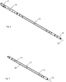
- Fig. 2 is schematically shown in a view obliquely from behind a front portion of the drill string with rod sections 8 and a drill head 17.
- a transmitter section 18 is arranged with a transmitter, to which the linkage section 15 is connected.
- the transmitter in the transmitter section 18 is used to locate the drill head 17 or locations of the drill string.
- the drill head 17 with subsequent transmitter section 18 and linkage section 15 and the rod sections 8 follows the earth bore, which is created in the ground.
- the linkage section 15 With the linkage section 15, the curvature of the Erdbohrlochsverlaufs can be detected.
- the linkage section 15 detects a bending load.
- the linkage section 15 is in the Fig. 3 shown enlarged.
- the linkage section 15 has a rod-shaped section 19 whose diameter is smaller than the diameter of the rod sections 8.
- the rod-shaped portion 19 is surrounded by a protective sheath 20, which has an outer dimension substantially corresponding to the dimensions of drill head 17 and transmitter section 18.
- the protective cover 20 protects the rod-shaped portion, which is hollow.
- the protective cover 20 protects strain sensors 21 arranged on the rod-shaped section 19, which essentially are mounted centrally with respect to the longitudinal extent of the rod-shaped portion 19 at this.
- a cable 22 is transmitted for connection to a receiving device 23, which transmits the data to a control of the Erdbohrvortechnisch or the evaluation device 13.
- a wireless transmission of the values of the strain sensors 21 to the receiving device 23 can take place.
- the receiving device 23 is wired or wirelessly connected to the evaluation device 13.
- the receiving device 23 transmits to the evaluation device 13 the signals of the strain sensor 21 in evaluated form and / or raw version, so that the evaluation device 13, taking into account the data of the pressure sensor 9, can make a lifetime calculation for the linkage or the individual linkage 8.
Landscapes
- Physics & Mathematics (AREA)
- Life Sciences & Earth Sciences (AREA)
- Engineering & Computer Science (AREA)
- Geology (AREA)
- Mining & Mineral Resources (AREA)
- Geophysics (AREA)
- Environmental & Geological Engineering (AREA)
- Fluid Mechanics (AREA)
- General Life Sciences & Earth Sciences (AREA)
- Geochemistry & Mineralogy (AREA)
- Force Measurement Appropriate To Specific Purposes (AREA)
- Earth Drilling (AREA)
Priority Applications (1)
| Application Number | Priority Date | Filing Date | Title |
|---|---|---|---|
| EP20165948.9A EP3690185B1 (fr) | 2017-08-18 | 2018-06-25 | Procédé de détermination de l'usure d'une tige d'un dispositif de forage du sol |
Applications Claiming Priority (1)
| Application Number | Priority Date | Filing Date | Title |
|---|---|---|---|
| DE102017118853.3A DE102017118853A1 (de) | 2017-08-18 | 2017-08-18 | Verfahren zum Bestimmen eines Verschleißes eines Gestänges einer Erdbohrvorrichtung |
Related Child Applications (2)
| Application Number | Title | Priority Date | Filing Date |
|---|---|---|---|
| EP20165948.9A Division-Into EP3690185B1 (fr) | 2017-08-18 | 2018-06-25 | Procédé de détermination de l'usure d'une tige d'un dispositif de forage du sol |
| EP20165948.9A Division EP3690185B1 (fr) | 2017-08-18 | 2018-06-25 | Procédé de détermination de l'usure d'une tige d'un dispositif de forage du sol |
Publications (2)
| Publication Number | Publication Date |
|---|---|
| EP3444433A1 true EP3444433A1 (fr) | 2019-02-20 |
| EP3444433B1 EP3444433B1 (fr) | 2020-06-17 |
Family
ID=62778746
Family Applications (2)
| Application Number | Title | Priority Date | Filing Date |
|---|---|---|---|
| EP18179478.5A Active EP3444433B1 (fr) | 2017-08-18 | 2018-06-25 | Procédé de détermination de l'usure d'une tige d'un dispositif de forage de puits |
| EP20165948.9A Not-in-force EP3690185B1 (fr) | 2017-08-18 | 2018-06-25 | Procédé de détermination de l'usure d'une tige d'un dispositif de forage du sol |
Family Applications After (1)
| Application Number | Title | Priority Date | Filing Date |
|---|---|---|---|
| EP20165948.9A Not-in-force EP3690185B1 (fr) | 2017-08-18 | 2018-06-25 | Procédé de détermination de l'usure d'une tige d'un dispositif de forage du sol |
Country Status (4)
| Country | Link |
|---|---|
| US (1) | US11566512B2 (fr) |
| EP (2) | EP3444433B1 (fr) |
| AU (1) | AU2018217302B2 (fr) |
| DE (1) | DE102017118853A1 (fr) |
Cited By (1)
| Publication number | Priority date | Publication date | Assignee | Title |
|---|---|---|---|---|
| DE102019002549A1 (de) * | 2019-04-08 | 2020-10-08 | TRACTO-TECHNlK GmbH & Co. KG | Erdbohrvorrichtung, Transfervorrichtung einer Erdbohrvorrichtung, Steuerung einer Transfervorrichtung einer Erdbohrvorrichtung und Verfahren zur Steuerung einer Erdbohrvorrichtung |
Citations (4)
| Publication number | Priority date | Publication date | Assignee | Title |
|---|---|---|---|---|
| US4715451A (en) * | 1986-09-17 | 1987-12-29 | Atlantic Richfield Company | Measuring drillstem loading and behavior |
| US6021377A (en) * | 1995-10-23 | 2000-02-01 | Baker Hughes Incorporated | Drilling system utilizing downhole dysfunctions for determining corrective actions and simulating drilling conditions |
| WO2010046099A1 (fr) * | 2008-10-21 | 2010-04-29 | Tractor-Technik Gmbh & Co. Kg | Procédé pour déterminer l'usure d'une tige, soumise à des forces, d'un équipement de terrassement |
| DE112013007353T5 (de) * | 2013-08-20 | 2016-04-28 | Halliburton Energy Services, Inc. | Bohrlochbohroptimierungskragen mit Glasfasern |
Family Cites Families (3)
| Publication number | Priority date | Publication date | Assignee | Title |
|---|---|---|---|---|
| US4547833A (en) * | 1983-12-23 | 1985-10-15 | Schlumberger Technology Corporation | High density electronics packaging system for hostile environment |
| US9945223B2 (en) * | 2014-08-14 | 2018-04-17 | Schlumberger Technology Corporation | Fatigue calculator generation system |
| CN106795754A (zh) * | 2014-11-10 | 2017-05-31 | 哈利伯顿能源服务公司 | 用于监测井筒弯曲度的方法和设备 |
-
2017
- 2017-08-18 DE DE102017118853.3A patent/DE102017118853A1/de not_active Withdrawn
-
2018
- 2018-06-25 EP EP18179478.5A patent/EP3444433B1/fr active Active
- 2018-06-25 EP EP20165948.9A patent/EP3690185B1/fr not_active Not-in-force
- 2018-08-14 US US16/103,216 patent/US11566512B2/en active Active
- 2018-08-17 AU AU2018217302A patent/AU2018217302B2/en active Active
Patent Citations (5)
| Publication number | Priority date | Publication date | Assignee | Title |
|---|---|---|---|---|
| US4715451A (en) * | 1986-09-17 | 1987-12-29 | Atlantic Richfield Company | Measuring drillstem loading and behavior |
| US6021377A (en) * | 1995-10-23 | 2000-02-01 | Baker Hughes Incorporated | Drilling system utilizing downhole dysfunctions for determining corrective actions and simulating drilling conditions |
| WO2010046099A1 (fr) * | 2008-10-21 | 2010-04-29 | Tractor-Technik Gmbh & Co. Kg | Procédé pour déterminer l'usure d'une tige, soumise à des forces, d'un équipement de terrassement |
| DE102008052510B3 (de) | 2008-10-21 | 2010-07-22 | Tracto-Technik Gmbh & Co. Kg | Verfahren zum Bestimmen des Verschleißes eines mit Kräften belasteten Gestänges einer Erdarbeitsvorrichtung |
| DE112013007353T5 (de) * | 2013-08-20 | 2016-04-28 | Halliburton Energy Services, Inc. | Bohrlochbohroptimierungskragen mit Glasfasern |
Non-Patent Citations (1)
| Title |
|---|
| WU J: "MODEL PREDICTS DRILL PIPE FATIGUE IN HORIZONTAL WELLS", OIL AND GAS JOURNAL, PENNWELL, HOUSTON, TX, US, vol. 95, no. 5, 3 February 1997 (1997-02-03), pages 47/48,51 - 53, XP000690298, ISSN: 0030-1388 * |
Cited By (3)
| Publication number | Priority date | Publication date | Assignee | Title |
|---|---|---|---|---|
| DE102019002549A1 (de) * | 2019-04-08 | 2020-10-08 | TRACTO-TECHNlK GmbH & Co. KG | Erdbohrvorrichtung, Transfervorrichtung einer Erdbohrvorrichtung, Steuerung einer Transfervorrichtung einer Erdbohrvorrichtung und Verfahren zur Steuerung einer Erdbohrvorrichtung |
| EP3722552A2 (fr) | 2019-04-08 | 2020-10-14 | TRACTO-TECHNIK GmbH & Co. KG | Dispositif de forage du sol, dispositif de transfert d'un dispositif de forage du sol, commande d'un dispositif de transfert d'un dispositif de forage du sol et procédé de commande d'un dispositif de forage du sol |
| US11401755B2 (en) | 2019-04-08 | 2022-08-02 | Tracto-Technik Gmbh & Co. Kg | Ground drilling device, transfer device of a ground drilling device, control of a transfer device of a ground drilling device and method for control of a ground drilling device |
Also Published As
| Publication number | Publication date |
|---|---|
| EP3444433B1 (fr) | 2020-06-17 |
| US20190055831A1 (en) | 2019-02-21 |
| EP3690185A1 (fr) | 2020-08-05 |
| EP3690185B1 (fr) | 2021-12-22 |
| DE102017118853A1 (de) | 2019-02-21 |
| AU2018217302B2 (en) | 2020-05-14 |
| US11566512B2 (en) | 2023-01-31 |
| AU2018217302A1 (en) | 2019-03-07 |
Similar Documents
| Publication | Publication Date | Title |
|---|---|---|
| DE102015105908B4 (de) | Bohrgerät zum Erstellen einer verrohrten Bohrung und Verfahren zum Betreiben eines Bohrgerätes | |
| DE69923907T2 (de) | Druckmessung von Erdformationen mit einer durchdringbaren Probe | |
| EP2543770B1 (fr) | Dispositif et procédé de mesure de colonnes de sortie de tuyères en sous-sol | |
| EP2035767B1 (fr) | Procédé et dispositif pour déterminer des déplacement et/ou des déformations dans une construction souterraine | |
| DE102008052510B3 (de) | Verfahren zum Bestimmen des Verschleißes eines mit Kräften belasteten Gestänges einer Erdarbeitsvorrichtung | |
| DE112010005996T5 (de) | Antriebseinheit für ein kraftbetriebenes Werkzeug | |
| DE112013007353T5 (de) | Bohrlochbohroptimierungskragen mit Glasfasern | |
| DE60123545T2 (de) | Erzeugen eines pfahles durch schneckenbohren | |
| DE69010627T2 (de) | Verfahren und Gerät zur Messung von Bodenschwankungen. | |
| EP3124740B1 (fr) | Dispositif de forage et procédé d'établissement d'un forage depuis une plateforme flottante | |
| EP3690185B1 (fr) | Procédé de détermination de l'usure d'une tige d'un dispositif de forage du sol | |
| EP4183974B1 (fr) | Système de tige creuse assisté par capteur | |
| DE2535794A1 (de) | Messvorrichtung fuer ein penetrometer | |
| AT399000B (de) | Erfassung der neigung von grabungen | |
| DE102005038313B4 (de) | Verfahren zur Messung der geologischen Lagerungsdichte und zur Detektion von Hohlräumen im Bereich eines Vortriebstunnels | |
| EP4141211A1 (fr) | Sondeur de détection du matériel militaire | |
| EP4015766A1 (fr) | Outil de génie civil et procédé de génie civil | |
| AT394449B (de) | Vorrichtung zur bestimmung von zug- und/oder druckspannungen sowie verfahren zum setzen derselben | |
| DE102005011968B4 (de) | Vorrichtung zur Herstellung von Bohrungen im Erdreich | |
| DE4438166C2 (de) | Vorrichtung zur Ermittlung des Kolbenhubs eines druckmittelbetätigten Arbeitszylinders | |
| DE2312078C3 (de) | Verfahren und Vorrichtung zur Überwachung der Vortriebsrichtung unterirdisch vorpressbarer Rohr- oder Tunnelschilde | |
| DE202021106176U1 (de) | Bohrer zur Kampfmitteldetektion | |
| EP2539531A2 (fr) | Procédé et dispositif de forage | |
| DE4430074C2 (de) | Verfahren und Vorrichtung zum Messen von Spannungen in Fels- oder Mauerwerk | |
| DD251198A1 (de) | Sonde zur messung der gebirgsaufblaetterung um bergmaennische hohlraeume |
Legal Events
| Date | Code | Title | Description |
|---|---|---|---|
| PUAI | Public reference made under article 153(3) epc to a published international application that has entered the european phase |
Free format text: ORIGINAL CODE: 0009012 |
|
| STAA | Information on the status of an ep patent application or granted ep patent |
Free format text: STATUS: THE APPLICATION HAS BEEN PUBLISHED |
|
| AK | Designated contracting states |
Kind code of ref document: A1 Designated state(s): AL AT BE BG CH CY CZ DE DK EE ES FI FR GB GR HR HU IE IS IT LI LT LU LV MC MK MT NL NO PL PT RO RS SE SI SK SM TR |
|
| AX | Request for extension of the european patent |
Extension state: BA ME |
|
| STAA | Information on the status of an ep patent application or granted ep patent |
Free format text: STATUS: REQUEST FOR EXAMINATION WAS MADE |
|
| 17P | Request for examination filed |
Effective date: 20190808 |
|
| RBV | Designated contracting states (corrected) |
Designated state(s): AL AT BE BG CH CY CZ DE DK EE ES FI FR GB GR HR HU IE IS IT LI LT LU LV MC MK MT NL NO PL PT RO RS SE SI SK SM TR |
|
| GRAP | Despatch of communication of intention to grant a patent |
Free format text: ORIGINAL CODE: EPIDOSNIGR1 |
|
| STAA | Information on the status of an ep patent application or granted ep patent |
Free format text: STATUS: GRANT OF PATENT IS INTENDED |
|
| RIC1 | Information provided on ipc code assigned before grant |
Ipc: E21B 47/00 20120101AFI20191210BHEP Ipc: E21B 47/01 20120101ALI20191210BHEP |
|
| INTG | Intention to grant announced |
Effective date: 20200109 |
|
| GRAS | Grant fee paid |
Free format text: ORIGINAL CODE: EPIDOSNIGR3 |
|
| GRAA | (expected) grant |
Free format text: ORIGINAL CODE: 0009210 |
|
| STAA | Information on the status of an ep patent application or granted ep patent |
Free format text: STATUS: THE PATENT HAS BEEN GRANTED |
|
| AK | Designated contracting states |
Kind code of ref document: B1 Designated state(s): AL AT BE BG CH CY CZ DE DK EE ES FI FR GB GR HR HU IE IS IT LI LT LU LV MC MK MT NL NO PL PT RO RS SE SI SK SM TR |
|
| REG | Reference to a national code |
Ref country code: GB Ref legal event code: FG4D Free format text: NOT ENGLISH |
|
| REG | Reference to a national code |
Ref country code: CH Ref legal event code: EP |
|
| REG | Reference to a national code |
Ref country code: DE Ref legal event code: R096 Ref document number: 502018001668 Country of ref document: DE |
|
| REG | Reference to a national code |
Ref country code: IE Ref legal event code: FG4D Free format text: LANGUAGE OF EP DOCUMENT: GERMAN |
|
| REG | Reference to a national code |
Ref country code: AT Ref legal event code: REF Ref document number: 1281516 Country of ref document: AT Kind code of ref document: T Effective date: 20200715 |
|
| PG25 | Lapsed in a contracting state [announced via postgrant information from national office to epo] |
Ref country code: NO Free format text: LAPSE BECAUSE OF FAILURE TO SUBMIT A TRANSLATION OF THE DESCRIPTION OR TO PAY THE FEE WITHIN THE PRESCRIBED TIME-LIMIT Effective date: 20200917 Ref country code: GR Free format text: LAPSE BECAUSE OF FAILURE TO SUBMIT A TRANSLATION OF THE DESCRIPTION OR TO PAY THE FEE WITHIN THE PRESCRIBED TIME-LIMIT Effective date: 20200918 Ref country code: LT Free format text: LAPSE BECAUSE OF FAILURE TO SUBMIT A TRANSLATION OF THE DESCRIPTION OR TO PAY THE FEE WITHIN THE PRESCRIBED TIME-LIMIT Effective date: 20200617 Ref country code: SE Free format text: LAPSE BECAUSE OF FAILURE TO SUBMIT A TRANSLATION OF THE DESCRIPTION OR TO PAY THE FEE WITHIN THE PRESCRIBED TIME-LIMIT Effective date: 20200617 Ref country code: FI Free format text: LAPSE BECAUSE OF FAILURE TO SUBMIT A TRANSLATION OF THE DESCRIPTION OR TO PAY THE FEE WITHIN THE PRESCRIBED TIME-LIMIT Effective date: 20200617 |
|
| REG | Reference to a national code |
Ref country code: LT Ref legal event code: MG4D |
|
| REG | Reference to a national code |
Ref country code: NL Ref legal event code: MP Effective date: 20200617 |
|
| PG25 | Lapsed in a contracting state [announced via postgrant information from national office to epo] |
Ref country code: BG Free format text: LAPSE BECAUSE OF FAILURE TO SUBMIT A TRANSLATION OF THE DESCRIPTION OR TO PAY THE FEE WITHIN THE PRESCRIBED TIME-LIMIT Effective date: 20200917 Ref country code: HR Free format text: LAPSE BECAUSE OF FAILURE TO SUBMIT A TRANSLATION OF THE DESCRIPTION OR TO PAY THE FEE WITHIN THE PRESCRIBED TIME-LIMIT Effective date: 20200617 Ref country code: LV Free format text: LAPSE BECAUSE OF FAILURE TO SUBMIT A TRANSLATION OF THE DESCRIPTION OR TO PAY THE FEE WITHIN THE PRESCRIBED TIME-LIMIT Effective date: 20200617 Ref country code: RS Free format text: LAPSE BECAUSE OF FAILURE TO SUBMIT A TRANSLATION OF THE DESCRIPTION OR TO PAY THE FEE WITHIN THE PRESCRIBED TIME-LIMIT Effective date: 20200617 |
|
| PG25 | Lapsed in a contracting state [announced via postgrant information from national office to epo] |
Ref country code: AL Free format text: LAPSE BECAUSE OF FAILURE TO SUBMIT A TRANSLATION OF THE DESCRIPTION OR TO PAY THE FEE WITHIN THE PRESCRIBED TIME-LIMIT Effective date: 20200617 Ref country code: NL Free format text: LAPSE BECAUSE OF FAILURE TO SUBMIT A TRANSLATION OF THE DESCRIPTION OR TO PAY THE FEE WITHIN THE PRESCRIBED TIME-LIMIT Effective date: 20200617 |
|
| PG25 | Lapsed in a contracting state [announced via postgrant information from national office to epo] |
Ref country code: PT Free format text: LAPSE BECAUSE OF FAILURE TO SUBMIT A TRANSLATION OF THE DESCRIPTION OR TO PAY THE FEE WITHIN THE PRESCRIBED TIME-LIMIT Effective date: 20201019 Ref country code: ES Free format text: LAPSE BECAUSE OF FAILURE TO SUBMIT A TRANSLATION OF THE DESCRIPTION OR TO PAY THE FEE WITHIN THE PRESCRIBED TIME-LIMIT Effective date: 20200617 Ref country code: IT Free format text: LAPSE BECAUSE OF FAILURE TO SUBMIT A TRANSLATION OF THE DESCRIPTION OR TO PAY THE FEE WITHIN THE PRESCRIBED TIME-LIMIT Effective date: 20200617 Ref country code: RO Free format text: LAPSE BECAUSE OF FAILURE TO SUBMIT A TRANSLATION OF THE DESCRIPTION OR TO PAY THE FEE WITHIN THE PRESCRIBED TIME-LIMIT Effective date: 20200617 Ref country code: CZ Free format text: LAPSE BECAUSE OF FAILURE TO SUBMIT A TRANSLATION OF THE DESCRIPTION OR TO PAY THE FEE WITHIN THE PRESCRIBED TIME-LIMIT Effective date: 20200617 Ref country code: SM Free format text: LAPSE BECAUSE OF FAILURE TO SUBMIT A TRANSLATION OF THE DESCRIPTION OR TO PAY THE FEE WITHIN THE PRESCRIBED TIME-LIMIT Effective date: 20200617 Ref country code: EE Free format text: LAPSE BECAUSE OF FAILURE TO SUBMIT A TRANSLATION OF THE DESCRIPTION OR TO PAY THE FEE WITHIN THE PRESCRIBED TIME-LIMIT Effective date: 20200617 |
|
| PG25 | Lapsed in a contracting state [announced via postgrant information from national office to epo] |
Ref country code: SK Free format text: LAPSE BECAUSE OF FAILURE TO SUBMIT A TRANSLATION OF THE DESCRIPTION OR TO PAY THE FEE WITHIN THE PRESCRIBED TIME-LIMIT Effective date: 20200617 Ref country code: PL Free format text: LAPSE BECAUSE OF FAILURE TO SUBMIT A TRANSLATION OF THE DESCRIPTION OR TO PAY THE FEE WITHIN THE PRESCRIBED TIME-LIMIT Effective date: 20200617 Ref country code: IS Free format text: LAPSE BECAUSE OF FAILURE TO SUBMIT A TRANSLATION OF THE DESCRIPTION OR TO PAY THE FEE WITHIN THE PRESCRIBED TIME-LIMIT Effective date: 20201017 |
|
| REG | Reference to a national code |
Ref country code: DE Ref legal event code: R097 Ref document number: 502018001668 Country of ref document: DE |
|
| PG25 | Lapsed in a contracting state [announced via postgrant information from national office to epo] |
Ref country code: LU Free format text: LAPSE BECAUSE OF NON-PAYMENT OF DUE FEES Effective date: 20200625 Ref country code: MC Free format text: LAPSE BECAUSE OF FAILURE TO SUBMIT A TRANSLATION OF THE DESCRIPTION OR TO PAY THE FEE WITHIN THE PRESCRIBED TIME-LIMIT Effective date: 20200617 |
|
| REG | Reference to a national code |
Ref country code: BE Ref legal event code: MM Effective date: 20200630 |
|
| PLBE | No opposition filed within time limit |
Free format text: ORIGINAL CODE: 0009261 |
|
| STAA | Information on the status of an ep patent application or granted ep patent |
Free format text: STATUS: NO OPPOSITION FILED WITHIN TIME LIMIT |
|
| PG25 | Lapsed in a contracting state [announced via postgrant information from national office to epo] |
Ref country code: DK Free format text: LAPSE BECAUSE OF FAILURE TO SUBMIT A TRANSLATION OF THE DESCRIPTION OR TO PAY THE FEE WITHIN THE PRESCRIBED TIME-LIMIT Effective date: 20200617 Ref country code: IE Free format text: LAPSE BECAUSE OF NON-PAYMENT OF DUE FEES Effective date: 20200625 |
|
| 26N | No opposition filed |
Effective date: 20210318 |
|
| PG25 | Lapsed in a contracting state [announced via postgrant information from national office to epo] |
Ref country code: SI Free format text: LAPSE BECAUSE OF FAILURE TO SUBMIT A TRANSLATION OF THE DESCRIPTION OR TO PAY THE FEE WITHIN THE PRESCRIBED TIME-LIMIT Effective date: 20200617 Ref country code: BE Free format text: LAPSE BECAUSE OF NON-PAYMENT OF DUE FEES Effective date: 20200630 |
|
| REG | Reference to a national code |
Ref country code: CH Ref legal event code: PL |
|
| PG25 | Lapsed in a contracting state [announced via postgrant information from national office to epo] |
Ref country code: LI Free format text: LAPSE BECAUSE OF NON-PAYMENT OF DUE FEES Effective date: 20210630 Ref country code: CH Free format text: LAPSE BECAUSE OF NON-PAYMENT OF DUE FEES Effective date: 20210630 |
|
| PG25 | Lapsed in a contracting state [announced via postgrant information from national office to epo] |
Ref country code: TR Free format text: LAPSE BECAUSE OF FAILURE TO SUBMIT A TRANSLATION OF THE DESCRIPTION OR TO PAY THE FEE WITHIN THE PRESCRIBED TIME-LIMIT Effective date: 20200617 Ref country code: MT Free format text: LAPSE BECAUSE OF FAILURE TO SUBMIT A TRANSLATION OF THE DESCRIPTION OR TO PAY THE FEE WITHIN THE PRESCRIBED TIME-LIMIT Effective date: 20200617 Ref country code: CY Free format text: LAPSE BECAUSE OF FAILURE TO SUBMIT A TRANSLATION OF THE DESCRIPTION OR TO PAY THE FEE WITHIN THE PRESCRIBED TIME-LIMIT Effective date: 20200617 |
|
| PG25 | Lapsed in a contracting state [announced via postgrant information from national office to epo] |
Ref country code: MK Free format text: LAPSE BECAUSE OF FAILURE TO SUBMIT A TRANSLATION OF THE DESCRIPTION OR TO PAY THE FEE WITHIN THE PRESCRIBED TIME-LIMIT Effective date: 20200617 |
|
| PGFP | Annual fee paid to national office [announced via postgrant information from national office to epo] |
Ref country code: FR Payment date: 20230622 Year of fee payment: 6 |
|
| PGFP | Annual fee paid to national office [announced via postgrant information from national office to epo] |
Ref country code: GB Payment date: 20230622 Year of fee payment: 6 |
|
| PGFP | Annual fee paid to national office [announced via postgrant information from national office to epo] |
Ref country code: DE Payment date: 20230720 Year of fee payment: 6 |
|
| REG | Reference to a national code |
Ref country code: AT Ref legal event code: MM01 Ref document number: 1281516 Country of ref document: AT Kind code of ref document: T Effective date: 20230625 |
|
| PG25 | Lapsed in a contracting state [announced via postgrant information from national office to epo] |
Ref country code: AT Free format text: LAPSE BECAUSE OF NON-PAYMENT OF DUE FEES Effective date: 20230625 |
|
| PG25 | Lapsed in a contracting state [announced via postgrant information from national office to epo] |
Ref country code: AT Free format text: LAPSE BECAUSE OF NON-PAYMENT OF DUE FEES Effective date: 20230625 |
|
| REG | Reference to a national code |
Ref country code: DE Ref legal event code: R119 Ref document number: 502018001668 Country of ref document: DE |
|
| GBPC | Gb: european patent ceased through non-payment of renewal fee |
Effective date: 20240625 |
|
| PG25 | Lapsed in a contracting state [announced via postgrant information from national office to epo] |
Ref country code: DE Free format text: LAPSE BECAUSE OF NON-PAYMENT OF DUE FEES Effective date: 20250101 |
|
| PG25 | Lapsed in a contracting state [announced via postgrant information from national office to epo] |
Ref country code: FR Free format text: LAPSE BECAUSE OF NON-PAYMENT OF DUE FEES Effective date: 20240630 |
|
| PG25 | Lapsed in a contracting state [announced via postgrant information from national office to epo] |
Ref country code: GB Free format text: LAPSE BECAUSE OF NON-PAYMENT OF DUE FEES Effective date: 20240625 |
|
| PGFP | Annual fee paid to national office [announced via postgrant information from national office to epo] |
Ref country code: AT Payment date: 20260410 Year of fee payment: 5 |