EP3444435B1 - Expansionsdichtun für schaufelblatt eines gasturbinentriebwerks - Google Patents
Expansionsdichtun für schaufelblatt eines gasturbinentriebwerks Download PDFInfo
- Publication number
- EP3444435B1 EP3444435B1 EP18189024.5A EP18189024A EP3444435B1 EP 3444435 B1 EP3444435 B1 EP 3444435B1 EP 18189024 A EP18189024 A EP 18189024A EP 3444435 B1 EP3444435 B1 EP 3444435B1
- Authority
- EP
- European Patent Office
- Prior art keywords
- airfoil
- expansion seal
- cavity
- expansion
- seal
- Prior art date
- Legal status (The legal status is an assumption and is not a legal conclusion. Google has not performed a legal analysis and makes no representation as to the accuracy of the status listed.)
- Active
Links
Images


Classifications
-
- F—MECHANICAL ENGINEERING; LIGHTING; HEATING; WEAPONS; BLASTING
- F01—MACHINES OR ENGINES IN GENERAL; ENGINE PLANTS IN GENERAL; STEAM ENGINES
- F01D—NON-POSITIVE DISPLACEMENT MACHINES OR ENGINES, e.g. STEAM TURBINES
- F01D5/00—Blades; Blade-carrying members; Heating, heat-insulating, cooling or antivibration means on the blades or the members
- F01D5/12—Blades
- F01D5/14—Form or construction
- F01D5/147—Construction, i.e. structural features, e.g. of weight-saving hollow blades
-
- F—MECHANICAL ENGINEERING; LIGHTING; HEATING; WEAPONS; BLASTING
- F01—MACHINES OR ENGINES IN GENERAL; ENGINE PLANTS IN GENERAL; STEAM ENGINES
- F01D—NON-POSITIVE DISPLACEMENT MACHINES OR ENGINES, e.g. STEAM TURBINES
- F01D25/00—Component parts, details, or accessories, not provided for in, or of interest apart from, other groups
- F01D25/005—Selecting particular materials
-
- F—MECHANICAL ENGINEERING; LIGHTING; HEATING; WEAPONS; BLASTING
- F01—MACHINES OR ENGINES IN GENERAL; ENGINE PLANTS IN GENERAL; STEAM ENGINES
- F01D—NON-POSITIVE DISPLACEMENT MACHINES OR ENGINES, e.g. STEAM TURBINES
- F01D25/00—Component parts, details, or accessories, not provided for in, or of interest apart from, other groups
- F01D25/08—Cooling; Heating; Heat-insulation
- F01D25/12—Cooling
-
- F—MECHANICAL ENGINEERING; LIGHTING; HEATING; WEAPONS; BLASTING
- F01—MACHINES OR ENGINES IN GENERAL; ENGINE PLANTS IN GENERAL; STEAM ENGINES
- F01D—NON-POSITIVE DISPLACEMENT MACHINES OR ENGINES, e.g. STEAM TURBINES
- F01D5/00—Blades; Blade-carrying members; Heating, heat-insulating, cooling or antivibration means on the blades or the members
- F01D5/12—Blades
- F01D5/14—Form or construction
- F01D5/18—Hollow blades, i.e. blades with cooling or heating channels or cavities; Heating, heat-insulating or cooling means on blades
- F01D5/187—Convection cooling
- F01D5/188—Convection cooling with an insert in the blade cavity to guide the cooling fluid, e.g. forming a separation wall
-
- F—MECHANICAL ENGINEERING; LIGHTING; HEATING; WEAPONS; BLASTING
- F01—MACHINES OR ENGINES IN GENERAL; ENGINE PLANTS IN GENERAL; STEAM ENGINES
- F01D—NON-POSITIVE DISPLACEMENT MACHINES OR ENGINES, e.g. STEAM TURBINES
- F01D5/00—Blades; Blade-carrying members; Heating, heat-insulating, cooling or antivibration means on the blades or the members
- F01D5/12—Blades
- F01D5/28—Selecting particular materials; Particular measures relating thereto; Measures against erosion or corrosion
- F01D5/282—Selecting composite materials, e.g. blades with reinforcing filaments
-
- F—MECHANICAL ENGINEERING; LIGHTING; HEATING; WEAPONS; BLASTING
- F01—MACHINES OR ENGINES IN GENERAL; ENGINE PLANTS IN GENERAL; STEAM ENGINES
- F01D—NON-POSITIVE DISPLACEMENT MACHINES OR ENGINES, e.g. STEAM TURBINES
- F01D5/00—Blades; Blade-carrying members; Heating, heat-insulating, cooling or antivibration means on the blades or the members
- F01D5/12—Blades
- F01D5/28—Selecting particular materials; Particular measures relating thereto; Measures against erosion or corrosion
- F01D5/284—Selection of ceramic materials
-
- F—MECHANICAL ENGINEERING; LIGHTING; HEATING; WEAPONS; BLASTING
- F01—MACHINES OR ENGINES IN GENERAL; ENGINE PLANTS IN GENERAL; STEAM ENGINES
- F01D—NON-POSITIVE DISPLACEMENT MACHINES OR ENGINES, e.g. STEAM TURBINES
- F01D9/00—Stators
- F01D9/02—Nozzles; Nozzle boxes; Stator blades; Guide conduits, e.g. individual nozzles
- F01D9/04—Nozzles; Nozzle boxes; Stator blades; Guide conduits, e.g. individual nozzles forming ring or sector
- F01D9/041—Nozzles; Nozzle boxes; Stator blades; Guide conduits, e.g. individual nozzles forming ring or sector using blades
-
- F—MECHANICAL ENGINEERING; LIGHTING; HEATING; WEAPONS; BLASTING
- F01—MACHINES OR ENGINES IN GENERAL; ENGINE PLANTS IN GENERAL; STEAM ENGINES
- F01D—NON-POSITIVE DISPLACEMENT MACHINES OR ENGINES, e.g. STEAM TURBINES
- F01D9/00—Stators
- F01D9/06—Fluid supply conduits to nozzles or the like
- F01D9/065—Fluid supply or removal conduits traversing the working fluid flow, e.g. for lubrication-, cooling-, or sealing fluids
-
- F—MECHANICAL ENGINEERING; LIGHTING; HEATING; WEAPONS; BLASTING
- F05—INDEXING SCHEMES RELATING TO ENGINES OR PUMPS IN VARIOUS SUBCLASSES OF CLASSES F01-F04
- F05D—INDEXING SCHEME FOR ASPECTS RELATING TO NON-POSITIVE-DISPLACEMENT MACHINES OR ENGINES, GAS-TURBINES OR JET-PROPULSION PLANTS
- F05D2220/00—Application
- F05D2220/30—Application in turbines
- F05D2220/32—Application in turbines in gas turbines
-
- F—MECHANICAL ENGINEERING; LIGHTING; HEATING; WEAPONS; BLASTING
- F05—INDEXING SCHEMES RELATING TO ENGINES OR PUMPS IN VARIOUS SUBCLASSES OF CLASSES F01-F04
- F05D—INDEXING SCHEME FOR ASPECTS RELATING TO NON-POSITIVE-DISPLACEMENT MACHINES OR ENGINES, GAS-TURBINES OR JET-PROPULSION PLANTS
- F05D2230/00—Manufacture
- F05D2230/20—Manufacture essentially without removing material
- F05D2230/23—Manufacture essentially without removing material by permanently joining parts together
- F05D2230/232—Manufacture essentially without removing material by permanently joining parts together by welding
-
- F—MECHANICAL ENGINEERING; LIGHTING; HEATING; WEAPONS; BLASTING
- F05—INDEXING SCHEMES RELATING TO ENGINES OR PUMPS IN VARIOUS SUBCLASSES OF CLASSES F01-F04
- F05D—INDEXING SCHEME FOR ASPECTS RELATING TO NON-POSITIVE-DISPLACEMENT MACHINES OR ENGINES, GAS-TURBINES OR JET-PROPULSION PLANTS
- F05D2230/00—Manufacture
- F05D2230/60—Assembly methods
-
- F—MECHANICAL ENGINEERING; LIGHTING; HEATING; WEAPONS; BLASTING
- F05—INDEXING SCHEMES RELATING TO ENGINES OR PUMPS IN VARIOUS SUBCLASSES OF CLASSES F01-F04
- F05D—INDEXING SCHEME FOR ASPECTS RELATING TO NON-POSITIVE-DISPLACEMENT MACHINES OR ENGINES, GAS-TURBINES OR JET-PROPULSION PLANTS
- F05D2240/00—Components
- F05D2240/55—Seals
-
- F—MECHANICAL ENGINEERING; LIGHTING; HEATING; WEAPONS; BLASTING
- F05—INDEXING SCHEMES RELATING TO ENGINES OR PUMPS IN VARIOUS SUBCLASSES OF CLASSES F01-F04
- F05D—INDEXING SCHEME FOR ASPECTS RELATING TO NON-POSITIVE-DISPLACEMENT MACHINES OR ENGINES, GAS-TURBINES OR JET-PROPULSION PLANTS
- F05D2250/00—Geometry
- F05D2250/10—Two-dimensional
- F05D2250/18—Two-dimensional patterned
- F05D2250/183—Two-dimensional patterned zigzag
-
- F—MECHANICAL ENGINEERING; LIGHTING; HEATING; WEAPONS; BLASTING
- F05—INDEXING SCHEMES RELATING TO ENGINES OR PUMPS IN VARIOUS SUBCLASSES OF CLASSES F01-F04
- F05D—INDEXING SCHEME FOR ASPECTS RELATING TO NON-POSITIVE-DISPLACEMENT MACHINES OR ENGINES, GAS-TURBINES OR JET-PROPULSION PLANTS
- F05D2250/00—Geometry
- F05D2250/10—Two-dimensional
- F05D2250/18—Two-dimensional patterned
- F05D2250/184—Two-dimensional patterned sinusoidal
-
- F—MECHANICAL ENGINEERING; LIGHTING; HEATING; WEAPONS; BLASTING
- F05—INDEXING SCHEMES RELATING TO ENGINES OR PUMPS IN VARIOUS SUBCLASSES OF CLASSES F01-F04
- F05D—INDEXING SCHEME FOR ASPECTS RELATING TO NON-POSITIVE-DISPLACEMENT MACHINES OR ENGINES, GAS-TURBINES OR JET-PROPULSION PLANTS
- F05D2250/00—Geometry
- F05D2250/10—Two-dimensional
- F05D2250/18—Two-dimensional patterned
- F05D2250/185—Two-dimensional patterned serpentine-like
-
- F—MECHANICAL ENGINEERING; LIGHTING; HEATING; WEAPONS; BLASTING
- F05—INDEXING SCHEMES RELATING TO ENGINES OR PUMPS IN VARIOUS SUBCLASSES OF CLASSES F01-F04
- F05D—INDEXING SCHEME FOR ASPECTS RELATING TO NON-POSITIVE-DISPLACEMENT MACHINES OR ENGINES, GAS-TURBINES OR JET-PROPULSION PLANTS
- F05D2250/00—Geometry
- F05D2250/70—Shape
- F05D2250/75—Shape given by its similarity to a letter, e.g. T-shaped
-
- F—MECHANICAL ENGINEERING; LIGHTING; HEATING; WEAPONS; BLASTING
- F05—INDEXING SCHEMES RELATING TO ENGINES OR PUMPS IN VARIOUS SUBCLASSES OF CLASSES F01-F04
- F05D—INDEXING SCHEME FOR ASPECTS RELATING TO NON-POSITIVE-DISPLACEMENT MACHINES OR ENGINES, GAS-TURBINES OR JET-PROPULSION PLANTS
- F05D2260/00—Function
- F05D2260/20—Heat transfer, e.g. cooling
- F05D2260/221—Improvement of heat transfer
- F05D2260/2214—Improvement of heat transfer by increasing the heat transfer surface
- F05D2260/22141—Improvement of heat transfer by increasing the heat transfer surface using fins or ribs
-
- F—MECHANICAL ENGINEERING; LIGHTING; HEATING; WEAPONS; BLASTING
- F05—INDEXING SCHEMES RELATING TO ENGINES OR PUMPS IN VARIOUS SUBCLASSES OF CLASSES F01-F04
- F05D—INDEXING SCHEME FOR ASPECTS RELATING TO NON-POSITIVE-DISPLACEMENT MACHINES OR ENGINES, GAS-TURBINES OR JET-PROPULSION PLANTS
- F05D2300/00—Materials; Properties thereof
- F05D2300/10—Metals, alloys or intermetallic compounds
- F05D2300/17—Alloys
- F05D2300/175—Superalloys
-
- F—MECHANICAL ENGINEERING; LIGHTING; HEATING; WEAPONS; BLASTING
- F05—INDEXING SCHEMES RELATING TO ENGINES OR PUMPS IN VARIOUS SUBCLASSES OF CLASSES F01-F04
- F05D—INDEXING SCHEME FOR ASPECTS RELATING TO NON-POSITIVE-DISPLACEMENT MACHINES OR ENGINES, GAS-TURBINES OR JET-PROPULSION PLANTS
- F05D2300/00—Materials; Properties thereof
- F05D2300/50—Intrinsic material properties or characteristics
- F05D2300/501—Elasticity
-
- F—MECHANICAL ENGINEERING; LIGHTING; HEATING; WEAPONS; BLASTING
- F05—INDEXING SCHEMES RELATING TO ENGINES OR PUMPS IN VARIOUS SUBCLASSES OF CLASSES F01-F04
- F05D—INDEXING SCHEME FOR ASPECTS RELATING TO NON-POSITIVE-DISPLACEMENT MACHINES OR ENGINES, GAS-TURBINES OR JET-PROPULSION PLANTS
- F05D2300/00—Materials; Properties thereof
- F05D2300/60—Properties or characteristics given to material by treatment or manufacturing
- F05D2300/603—Composites; e.g. fibre-reinforced
- F05D2300/6033—Ceramic matrix composites [CMC]
-
- Y—GENERAL TAGGING OF NEW TECHNOLOGICAL DEVELOPMENTS; GENERAL TAGGING OF CROSS-SECTIONAL TECHNOLOGIES SPANNING OVER SEVERAL SECTIONS OF THE IPC; TECHNICAL SUBJECTS COVERED BY FORMER USPC CROSS-REFERENCE ART COLLECTIONS [XRACs] AND DIGESTS
- Y02—TECHNOLOGIES OR APPLICATIONS FOR MITIGATION OR ADAPTATION AGAINST CLIMATE CHANGE
- Y02T—CLIMATE CHANGE MITIGATION TECHNOLOGIES RELATED TO TRANSPORTATION
- Y02T50/00—Aeronautics or air transport
- Y02T50/60—Efficient propulsion technologies, e.g. for aircraft
Definitions
- Illustrative embodiments pertain to the art of turbomachinery, and specifically to turbine rotor components.
- Gas turbine engines are rotary-type combustion turbine engines built around a power core made up of a compressor, combustor and turbine, arranged in flow series with an upstream inlet and downstream exhaust.
- the compressor compresses air from the inlet, which is mixed with fuel in the combustor and ignited to generate hot combustion gas.
- the turbine extracts energy from the expanding combustion gas, and drives the compressor via a common shaft. Energy is delivered in the form of rotational energy in the shaft, reactive thrust from the exhaust, or both.
- each spool is subdivided into a number of stages, which are formed of alternating rows of rotor blade and stator vane airfoils.
- the airfoils are shaped to turn, accelerate and compress the working fluid flow, or to generate lift for conversion to rotational energy in the turbine.
- Airfoils may incorporate various cooling cavities located adjacent external side walls. To provide necessary cooling, ribs or other internal structures may be formed within the airfoils during the casting or other manufacturing process. Such structures may increase the weight of the airfoil. Reducing the weight of airfoils may be advantageous.
- the present invention provides an airfoil for a gas turbine engine according to claim 1.
- the airfoils may include that the ends of the at least one expansion seal are welded to the smooth portion of the cavity wall.
- the airfoils may include that the at least one expansion seal is formed from an austenitic nickel-chromium-based superalloy, an austenitic nickel-based superalloy, or a nickel-molybdenum alloy.
- the airfoils may include that the at least one expansion seal comprises at least one undulation.
- the airfoils may include that the at least one expansion seal comprises a first expansion seal and a second expansion seal, wherein each of the first and second expansion seals may comprise at least one undulation.
- the airfoils may include that the first expansion seal comprises more undulations than the second expansion seal.
- the airfoils may include that the first expansion seal is positioned closer to the leading edge of the airfoil body than the second expansion seal, and the second expansion seal may be positioned closer to the trailing edge of the airfoil body than the first expansion seal.
- the airfoils may include that the smooth portion extends over the entire cavity wall.
- the airfoils may include that the airfoil body is made of ceramic matrix composite.
- the present invention provides a method of manufacturing airfoils for gas turbine engines according to claim 10.
- the methods may include fixing ends of the at least one expansion seal to the smooth cavity wall.
- the methods may include that the fixing comprises welding or tacking.
- the methods may include that the at least one expansion seal is formed from an austenitic nickel-chromium-based superalloy, an austenitic nickel-based superalloy, or a nickel-molybdenum alloy.
- the methods may include that the at least one expansion seal comprises a first expansion seal and a second expansion seal, wherein each of the first and second expansion seals comprises at least one undulation, the first expansion seal comprising more undulations than the second expansion seal, the method further comprising positioning the first expansion seal closer to the leading edge of the airfoil body than the second expansion seal, and positioning the second expansion seal closer to the trailing edge of the airfoil body than the first expansion seal.
- the methods may include manufacturing the airfoil body from ceramic matrix composite.
- FIG. 1 schematically illustrates a gas turbine engine 20.
- the gas turbine engine 20 is disclosed herein as a two-spool turbofan that generally incorporates a fan section 22, a compressor section 24, a combustor section 26 and a turbine section 28.
- Alternative engines might include an augmentor section (not shown) among other systems or features.
- the fan section 22 drives air along a bypass flow path B in a bypass duct, while the compressor section 24 drives air along a core flow path C for compression and communication into the combustor section 26 then expansion through the turbine section 28.
- the exemplary engine 20 generally includes a low speed spool 30 and a high speed spool 32 mounted for rotation about an engine central longitudinal axis A relative to an engine static structure 36 via several bearing systems 38. It should be understood that various bearing systems 38 at various locations may alternatively or additionally be provided, and the location of bearing systems 38 may be varied as appropriate to the application.
- the low speed spool 30 generally includes an inner shaft 40 that interconnects a fan 42, a low pressure compressor 44 and a low pressure turbine 46.
- the inner shaft 40 is connected to the fan 42 through a speed change mechanism, which in exemplary gas turbine engine 20 is illustrated as a geared architecture 48 to drive the fan 42 at a lower speed than the low speed spool 30.
- the high speed spool 32 includes an outer shaft 50 that interconnects a high pressure compressor 52 and high pressure turbine 54.
- a combustor 56 is arranged in exemplary gas turbine 20 between the high pressure compressor 52 and the high pressure turbine 54.
- An engine static structure 36 is arranged generally between the high pressure turbine 54 and the low pressure turbine 46.
- the engine static structure 36 further supports bearing systems 38 in the turbine section 28.
- the inner shaft 40 and the outer shaft 50 are concentric and rotate via bearing systems 38 about the engine central longitudinal axis A which is collinear with their longitudinal axes.
- each of the positions of the fan section 22, compressor section 24, combustor section 26, turbine section 28, and fan drive gear system 48 may be varied.
- gear system 48 may be located aft of combustor section 26 or even aft of turbine section 28, and fan section 22 may be positioned forward or aft of the location of gear system 48.
- the engine 20 in one example is a high-bypass geared aircraft engine.
- the engine 20 bypass ratio is greater than about six (6), with an example embodiment being greater than about ten (10)
- the geared architecture 48 is an epicyclic gear train, such as a planetary gear system or other gear system, with a gear reduction ratio of greater than about 2.3
- the low pressure turbine 46 has a pressure ratio that is greater than about five.
- the engine 20 bypass ratio is greater than about ten (10:1)
- the fan diameter is significantly larger than that of the low pressure compressor 44
- the low pressure turbine 46 has a pressure ratio that is greater than about five 5:1.
- Low pressure turbine 46 pressure ratio is pressure measured prior to inlet of low pressure turbine 46 as related to the pressure at the outlet of the low pressure turbine 46 prior to an exhaust nozzle.
- the geared architecture 48 may be an epicycle gear train, such as a planetary gear system or other gear system, with a gear reduction ratio of greater than about 2.3:1. It should be understood, however, that the above parameters are only exemplary of one embodiment of a geared architecture engine and that the present disclosure is applicable to other gas turbine engines including direct drive turbofans.
- the fan section 22 of the engine 20 is designed for a particular flight condition--typically cruise at about 0.8 Mach and about 10,668 meters (35,000 feet).
- "Low fan pressure ratio” is the pressure ratio across the fan blade alone, without a Fan Exit Guide Vane (“FEGV”) system.
- the low fan pressure ratio as disclosed herein according to one non-limiting embodiment is less than about 1.45.
- Low corrected fan tip speed is the actual fan tip speed in ft/sec divided by an industry standard temperature correction of [(Tram °R)/(514.7 °R)] 0.5 .
- the "Low corrected fan tip speed” as disclosed herein according to one non-limiting embodiment is less than about 350.5 m/sec (1150 ft/second).
- gas turbine engine 20 is depicted as a turbofan, it should be understood that the concepts described herein are not limited to use with the described configuration, as the teachings may be applied to other types of engines such as, but not limited to, turbojets, turboshafts, and three-spool (plus fan) turbofans wherein an intermediate spool includes an intermediate pressure compressor (“IPC") between a low pressure compressor (“LPC”) and a high pressure compressor (“HPC”), and an intermediate pressure turbine (“IPT”) between the high pressure turbine (“HPT”) and the low pressure turbine (“LPT”).
- IPC intermediate pressure compressor
- LPC low pressure compressor
- HPC high pressure compressor
- IPT intermediate pressure turbine
- FIG. 2 is a schematic view of a portion of the turbine section 28 that may employ various embodiments disclosed herein.
- Turbine section 28 includes a plurality of airfoils 60, 62 including, for example, one or more blades and vanes.
- the airfoils 60, 62 may be hollow bodies with internal cavities defining a number of channels or cores, hereinafter airfoil cores, formed therein and extending from an inner diameter 66 to an outer diameter 68, or vice-versa.
- the airfoil cores may be separated by partitions within the airfoils 60, 62 that may extend either from the inner diameter 66 or the outer diameter 68 of the airfoil 60, 62.
- the partitions may extend for a portion of the length of the airfoil 60, 62, but may stop or end prior to forming a complete wall within the airfoil 60, 62.
- each of the airfoil cores may be fluidly connected and form a fluid path within the respective airfoil 60, 62.
- the airfoils 60, 62 may include platforms 70 located proximal to the inner diameter 66 thereof. Located below the platforms 70 (e.g., radially inward with respect to the engine axis) may be airflow ports and/or bleed orifices that enable air to bleed from the internal cavities of the airfoils 60, 62. A root or first end of the airfoil may connect to or be part of the platform 70.
- the turbine section 28 is housed within a case 80, which may have multiple parts (e.g., turbine case, diffuser case, etc.). In various locations, components, such as seals, may be positioned between airfoils 60, 62 and the case 80.
- components such as seals
- FIG. 2 blade outer air seals 82 (hereafter "BOAS") are located radially outward from the blade 60.
- the BOAS 82 may include BOAS supports that are configured to fixedly connect or attach the BOAS 82 to the case 80 (e.g., the BOAS supports may be located between the BOAS 82 and the case 80).
- the case 80 includes a plurality of case hooks 84 that engage with BOAS hooks 86 to secure the BOAS 82 between the case 80 and a tip or second end of the airfoil 60.
- the airfoil 300 may be a blade or vane, such as that shown in FIG. 2 (blades 60, vanes 62).
- the airfoil 300 is a partially hollow, aerodynamic body including a pressure side 302, a suction side 304, a first end (e.g., root region, inner diameter, proximate a platform 70 as shown in FIG. 2 , etc.), a second end (e.g., tip region, outer diameter, proximate a BOAS 82 as shown in FIG. 2 , etc.), a leading edge 306, and a trailing edge 308.
- the airfoil 300 extends radially (into and out of the page of FIG. 3 ) from the first end to the second end. Further, the airfoil 300 extends in an axial direction from the leading edge 306 to the trailing edge 308.
- the directions and/or orientations described herein are made with respect to an engine axis when the airfoil 300 is installed in said engine (e.g., engine central longitudinal axis A shown in FIG. 1 ). Accordingly, as used herein, the term "radial" refers to radial with respect to an engine axis.
- the pressure side 302 is disposed opposite the suction side 304.
- the pressure side 302 and the suction side 304 each extend radially from the first end to the second end of the airfoil.
- the pressure side 302 and the suction side 304 each extend generally axially (e.g., with respect to the engine axis) between the leading edge 306 and the trailing edge 308.
- Each of the first end and the second end of the airfoil extend from the leading edge 306 to the trailing edge 308 opposite each other at ends of the airfoil body in the radial direction.
- the first end defines an inner radial end of the airfoil body and the second end defines an outer radial end of the airfoil body (relative to an engine axis).
- the airfoil 300 may be a blade or vane, and have various other features associated with such configurations, e.g., platforms, tip surfaces, etc.
- the airfoil 300 defines or includes a plurality of internal cavities to enable cooling of the airfoil 300.
- the airfoil 60 includes a plurality of cooling cavities 310, 312, 314.
- the cooling cavities 310, 312, 314 define a serpentine flow cavity as will be appreciated by those of skill in the art.
- a first cooling cavity 310 is located proximate the leading edge 306, a second cooling cavity 312 is located axially toward the trailing edge from the first cooling cavity 310 (i.e., "aftward") and is separated by a first rib 316.
- the third cooling cavity 314 is located aftward of the second cooling cavity 312 and is separated from the second cooling cavity 312 by a second rib 318.
- the ribs 316, 318 are cast ribs that are integrally formed with the body of the airfoil 300 and extend circumferentially between the pressure side 302 and the suction side 304, and separate the cooling cavities 310, 312, 314. Although described as separating the cooling cavities 310, 312, 314, those of skill in the art will appreciate that the ribs 316, 318 may not extend completely from a first end to a second end, and thus the various cooling cavities 310, 312, 314 may be fluidly connected to form a serpentine flow path through the airfoil 300.
- Air flowing through the cooling cavities 310, 312, 314 may exit the trailing edge 308 of the airfoil 300 through a trailing edge slot 320.
- the most aftward (aftflowing) cooling cavity 314 defines a serpentine trailing edge cavity that fluidly connects to the trailing edge slot 320 that is formed at the trailing edge 308.
- the first cooling cavity 310 is arranged for flow in a first direction (e.g., an up pass cooling flow), the second cooling cavity 312 is arranged for flow in a second direction (e.g., a down pass cooling flow), and the third cooling cavity 314 is arranged for flow in the first direction and/or a third direction (e.g., an up pass cooling flow that exits the airfoil 300 through the trailing edge slot 320).
- a first direction e.g., an up pass cooling flow
- the second cooling cavity 312 is arranged for flow in a second direction (e.g., a down pass cooling flow)
- the third cooling cavity 314 is arranged for flow in the first direction and/or a third direction (e.g., an up pass cooling flow that exits the airfoil 300 through the trailing edge slot 320).
- airfoils in accordance with the present disclosure may include additional and/or alternative cavities, flow paths, channels, etc. as will be appreciated by those of skill in the art, including, but
- the ribs are cast in with the body of the airfoil. Such casting of the ribs to separate the airfoil cooling cavities may increase the weight of the airfoil. Typical thickness of cast ribs is approximately 0.76 mm (0.030 inches).
- engine weight requirements are trending downward and thus reductions in weight of any components within an engine are advantageous.
- life requirements are trending upward, meaning that life cycle of components of the engines is increasing and thus part-life increases are advantageous.
- embodiments of the present disclosure are directed to airfoils having reduced weight, increased part-life, and reduced production costs and/or production times.
- embodiments of the present invention are directed to hollow body airfoils with smooth or uninterrupted interior areas and/or surfaces and expansion seals that are installed to operate as ribs within the airfoil (e.g., divide a central cavity into multiple sub-cavities, such as a serpentine flow path).
- the expansion seals can be compressed and inserted into airfoil cavities to serve as ribs.
- the biasing nature of the expansion seals allows the expansion seals to be compressed and inserted into the airfoil, resulting in a tight fit against a smooth, interior area of an airfoil wall during assembly.
- the inner-diameter (e.g., proximate the first end) and/or the outer-diameter (e.g., proximate the second end) ends of the expansion seals can be tack welded into place.
- the biasing nature of the expansion seals also allows the expansion seals to expand as the airfoil expands during engine operation, resulting in a tight fit throughout engine operation. Further, in some embodiments, depending on the cooling scheme, pressure differentials between two sub-cavities and the wedge shape of the airfoil can help keep the expansion seals in place and tight against the airfoil wall during engine operation.
- the expansion seals are biased or spring-loaded to enable engagement between a portion of the expansion seal and a surface of the airfoil.
- a “smooth" surface on the interior of the airfoil is a surface that does not include structures or features arranged to engage with inserts/rib structures. Such smooth surfaces further do not include flow or thermal transfer augmentation features (e.g., trip strips, etc.), but rather are smooth to enable a secure, sealing engagement with an end of an expansion seal. That is, a smooth, uninterrupted surface area of the interior cavity walls of the airfoil allows for unimpeded movement and placement of an expansion seal within an airfoil, as discussed herein.
- having a "smooth" portion of the surface area of the interior cavity walls of the airfoil does not exclude heat transfer augmentation features from being present on other portions of the interior surfaces of the airfoil cavity walls, such as trip strips within flow channels/cavities/sub-cavities that are defined by the inserted expansion seals.
- FIGS. 4A-4C schematic illustrations of an airfoil 400 in accordance with an embodiment of the present disclosure are shown.
- FIG. 4A is a side elevation view of the airfoil 400
- FIG. 4B is a cross-sectional illustration as viewed along the line A-A shown in FIG. 4A showing a hollow, single-cavity structure of the airfoil 400
- FIG. 4C is a cross-sectional illustration as viewed along the line A-A shown in FIG. 4A with an expansion seal 402 installed within an airfoil cavity 404.
- the airfoil 400 extends radially from a first end 406 (or inner diameter) to a second end 408 (or outer diameter), as shown and described above.
- the airfoil 400 further extends in a substantially axially direction from a leading edge 410 to a trailing edge 412.
- the airfoil 400 is positioned between a platform 414 at the first end 406 and an air seal 416 at the second end 408.
- the airfoil 400 includes a pressure side 418 and a suction side 420, with the airfoil cavity 404 therebetween and extending, in this embodiment, from the leading edge 410 to the trailing edge 412.
- the airfoil 400 is a hollow body airfoil with a single, unitary cavity formed therein.
- the airfoil cavity 404 is defined by a cavity wall 422.
- the airfoil cavity 404 extends radially from the first end 406 to the second end 408 of the airfoil 400, and in other embodiments, the airfoil cavity 404 may only extend partway between the first end 406 and the second end 408 of the airfoil 400.
- the airfoil cavity 404 can be divided into multiple sub-cavities 424, 426, as shown.
- the expansion seal 402 can be positioned within the airfoil 400 to divide the airfoil cavity 404 into a first sub-cavity 424 and a second sub-cavity 426.
- the expansion seal 402 substantially fluidly separates the first sub-cavity 424 from the second sub-cavity 426 along a radial length of the expansion seal 402.
- the expansion seal 402 extends substantially along the entire radial extent of the airfoil 400 (i.e., from first end 406 to second end 408), and thus divides the airfoil cavity 404 into two substantially independent cavities.
- the expansion seal 402 is an insert that is placed within the airfoil cavity 404 and then expands to engage with the cavity wall 422.
- the expansion seal 402 may be spring-loaded or biased such that the expansion seal 402 is at least partially compressed and positioned at a specific location within the airfoil cavity 404. The compression force is released, and the expansion seal 402 expands outward such that the expansion seal 402 engages with the cavity wall 422 and fixes the expansion seal 402 in place within the airfoil 400.
- the expansion seal 402 is shown in a compressed state in FIG. 4B and an expanded state in FIG. 4C .
- the expansion seal 402 may be compressed by a compression force F C .
- the compressed expansion seal 402 can then be moved or positioned at a desired location within the airfoil cavity 404.
- the natural tendency of the expansion seal 402 will be to expand with an expansion force F E , thus applying an engaging force with the cavity wall 422.
- the expansion seals of the present invention is made from 0.25 mm (0.010 inch) to 0.51 mm (0.020 inch) sheet metal, which is thinner and lighter than the typical 0.76 mm (0.030 inch) cast ribs.
- the expansion seals may be formed from sheet metal materials such as austenitic nickel-chromium-based superalloys, austenitic nickel-based superalloys, nickel-molybdenum alloys, and/or other metals, alloys, superalloys, etc. as will be appreciated by those of skill in the art. Such materials may have lower densities than cast, single crystal materials (e.g., typical airfoil manufacturing techniques that include a formed/integral rib).
- the expansion seals are separate pieces, the casting process for an airfoil is simplified, resulting in cheaper castings. Further, because the expansion seals are separate components from the airfoil itself, this enables quick changes to the cooling scheme by utilizing existing casting processes and adding or moving expansion seals within the airfoil cavity. Moreover, because the expansion seal is not attached to or part of the airfoil wall, stresses are reduced by eliminating thermal differences (e.g., expansion/contractions) between cold ribs and hot exterior walls of the airfoil.
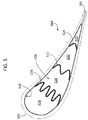
- FIG. 5 a schematic illustration of an airfoil 500 in accordance with an embodiment of the present disclosure is shown.
- the airfoil 500 is similar to that shown above, having a leading edge 502 and a trailing edge 504.
- the airfoil 500 defines an airfoil cavity 506 therein which is defined by a cavity wall 508.
- Installed within the airfoil cavity 506 are a plurality of expansion seals 510, 512, 514.
- the expansion seals 510, 512, 514 divide the airfoil cavity 506 into four sub-cavities (e.g., a first sub-cavity 516, a second sub-cavity 518, a third sub-cavity 520, and a fourth sub-cavity 522).
- sub-cavities e.g., a first sub-cavity 516, a second sub-cavity 518, a third sub-cavity 520, and a fourth sub-cavity 522).
- the expansion seals 510, 512, 514 each have different configurations, which is based, in part, on the location within the airfoil cavity 506 that the respective expansion seal 510, 512, 514 is placed.
- a first expansion seal 510 has four undulations which allows for extending across a wide portion of the airfoil cavity 506.
- a second expansion seal 512 has two undulations and expands across a narrower portion of the airfoil cavity 506.
- a third expansion seal 514 has a single undulation and spans an even narrower portion of the airfoil cavity 506.
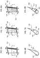
- FIGS. 6A-6B schematic illustrations of an airfoil 600 in accordance with an embodiment of the present disclosure is shown.
- FIG. 6A is a side, elevation illustration of the airfoil 600 having a single airfoil cavity 602 defined therein and
- FIG. 6B is a cross-sectional illustration as viewed along the line B-B.
- the airfoil 600 includes a cavity wall 604 having smooth portions that do not include any features that may obstruct flow through the airfoil cavity 602 or divide the airfoil cavity 602 into multiple cavities.
- a smooth cavity wall 604 enables placement and engagement of one or more expansion seals at any locations within the airfoil cavity 602. That is, because the walls are smooth, there will be no obstructions to defining and arranging sub-cavities within the airfoil 600.
- the smooth-walled cavity wall 604 may be in contrast to alternative arrangements of insertable ribs that may include grooves, channels, or other features to enable positioning an insertable rib within an airfoil.
- the smooth walled arrangement allows for ease of tacking, welding, or other fastening of one or more expansion seals to be installed within an airfoil. For example, as discussed below with respect to FIGS. 7A-8B , different arrangements (numbers, configurations, sizes, etc.) of expansion seals can be positioned within an airfoil cavity.
- FIGS. 7A-7B schematic illustrations of an airfoil 700 in accordance with an embodiment of the present disclosure is shown.
- FIG. 7A is a side, elevation illustration of the airfoil 700 having a single airfoil cavity defined therein and
- FIG. 7B is a cross-sectional illustration as viewed along the line B-B.
- the airfoil 700 includes a smooth cavity wall 704 that does not include any features that may obstruct flow through the airfoil cavity or divide the airfoil cavity into multiple cavities.
- a single expansion seal 706 has been inserted into the airfoil cavity to divide the interior of the airfoil 700 into a first sub-cavity 708 and a second sub-cavity 710.
- the expansion seal 706 is shown engaging with the smooth cavity wall 704.
- the location of the expansion seal 706 within the airfoil cavity may be based, in part, on a length of the expansion seal 706 and/or the amount of compression and/or expansion of the expansion seal 706 that is desired for a particular application.
- FIGS. 8A-8B schematic illustrations of an airfoil 800 described for explanatory purposes are shown.
- FIG. 8A is a side, elevation illustration of the airfoil 800 having a single airfoil cavity defined therein and
- FIG. 8B is a cross-sectional illustration as viewed along the line B-B.
- the airfoil 800 includes a smooth cavity wall 804 that does not include any features that may obstruct flow through the airfoil cavity or divide the airfoil cavity into multiple cavities.
- two expansion seals 812, 814 are shown inserted into the airfoil cavity to divide the interior of the airfoil 800 into a serpentine flow cavity 816.
- the expansion seals 812, 814 do not extend the full radial length of the airfoil 800, but rather stop short of a full radial extension. As such, the serpentine flow cavity 816 is formed within the airfoil 800.
- the expansion seals 812, 814 are shown engaging with the smooth cavity wall 804. The location of the expansion seals 812, 814 within the airfoil cavity may be based, in part, on a length of the expansion seals 812, 814 and/or the amount of compression and/or expansion of the expansion seals 812, 814 that is desired for a particular application.
- FIGS. 7A-7B illustrate the use of a single expansion seal and FIGS. 8A-8B illustrate the use of two expansion seals
- any number of expansion seals may be installed within an airfoil cavity.
- the single-seal arrangement of FIGS. 7A-7B illustrates a full, radial extension of the expansion seal within the airfoil
- the dual-seal arrangement of FIGS. 8A-8B illustrates partial radial extension of the expansion seals within the airfoil
- various other arrangements and/or combinations of arrangements may be employed without departing from the scope of the present disclosure.
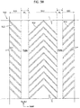
- FIG. 9A a schematic illustration of an installation process in accordance with an embodiment of the present disclosure is shown.
- an airfoil 900 having an airfoil cavity 902 is divided into having multiple sub-cavities by the installation of a first expansion seal 904 and a second expansion seal 906.
- the airfoil 900 extends in a generally aftward (axial) direction from a leading edge 908 to a trailing edge 910.
- the airfoil cavity 902 is defined by a cavity wall 912 having smooth portions 918a, 918b.
- FIG. 9B illustrates an elevation illustration of the interior, cavity wall 912 of the airfoil, illustrating the smooth portions 918a, 918b and augmentation portions 920 having augmentation features 922 (e.g., flow or thermal transfer augmentation features).
- the first expansion seal 904 is in a first or compressed state (shown in dashed lines) and is positioned within the airfoil cavity 902.
- the first expansion seal 904 is compressed by a compression force F C to reduce a length or size of the first expansion seal 904 and to enable installation within the airfoil cavity 902.
- the first expansion seal 904 is then moved aftward to the location of the first smooth portion 918a for installation.
- the compression force F C is then released and the first expansion seal 904 will expand outward by a natural expansion force F E of the first expansion seal 904.
- ends 914a, 914b of the first expansion seal 904 Upon expansion, ends 914a, 914b of the first expansion seal 904 will contact the smooth portions of the cavity wall 912 (e.g., a first smooth portion 918a shown in FIG. 9B ) and engage therewith.
- the expansion of the first expansion seal 904 may cause an interference fit or pressed engagement between the ends 914a, 914b of the first expansion seal 904 and the cavity wall 912 at the smooth portion 918a.
- welding, tacking, or other attachment and/or fixing operation can be employed to fixedly attach the first expansion seal 904 to the cavity wall 912.
- adhesives or other chemical and/or mechanical mechanism can be used to fix the first expansion seal 904 in place.
- the first expansion seal 904 has four undulations, which may be used to enable installation at a specific location within the airfoil cavity 902 (e.g., the number of undulations may dictate the length of the expansion seal and thus where it may fit within the airfoil).
- the second expansion seal 906 is in a first or compressed state (shown in dashed lines) and is positioned within the airfoil cavity 902.
- the second expansion seal 906 is compressed by a compression force F C to reduce a length or size of the second expansion seal 906 and to enable installation within the airfoil cavity 902.
- the second expansion seal 906 is then moved aftward to a desired location for installation.
- the compression force F C is then released and the second expansion seal 906 will expand outward by a natural expansion force F E of the second expansion seal 906.
- ends 916a, 916b of the second expansion seal 906 Upon expansion, ends 916a, 916b of the second expansion seal 906 will contact second smooth portions 918b of the cavity wall 912 and engage therewith.
- the expansion of the second expansion seal 906 may cause an interference fit or pressed engagement between the ends 916a, 916b of the second expansion seal 906 and the smooth portion 918b of the cavity wall 912. Subsequently, welding, tacking, or other attachment and/or fixing operation can be employed to fixedly attach the second expansion seal 906 to the smooth cavity wall 912. In some embodiments, adhesives or other chemical and/or mechanical mechanism can be used to fix the second expansion seal 906 in place. As shown, the second expansion seal 906 has two undulations, which may be used to enable installation at a specific location within the airfoil cavity 902 (e.g., the number of undulations may dictate the length of the expansion seal and thus where it may fit within the airfoil).
- the smooth portions 918a, 918b of the cavity wall 912 do not extend over the entire surface of the cavity wall 912, but rather are located at discrete or predetermined locations.
- the smooth portions 918a, 918b of the cavity wall 912 can have thicknesses W 1 , W 2 , respectively.
- the thicknesses W 1 , W 2 can be defined to allow for installation of the expansion seals 904, 906 at locations within the airfoil 900.
- the thicknesses W 1 , W 2 can be set to have a predetermined thickness to enable variable placement of the expansion seals 904, 906 along the cavity wall 912.
- the cavity 912 may include augmentation portions 920 located along the cavity wall 912 at locations not occupied by the smooth portions 918a, 918b.
- the augmentation portions 920 can include trip strips 922, as shown, or may include other flow augmentation and/or thermal transfer augmentation features, including, but not limited to, film holes, ribs, etc.
- the smooth portions 918a, 918b will extend in generally radial directions from the first end to the second end of the airfoil.
- the augmentation portions 920 may thus occupy the rest of the cavity wall 912 in a predetermined pattern to achieved desired cooling flow and/or thermal transfer within the airfoil 900.
- the entire cavity wall may be smooth and thus lack any features that may interfere with installation of one or more expansion seals.
- the expansion seal(s) may be installed at any desired location within the airfoil to form any desirable sub-cavity configuration.
- the augmentation portions may be arranged such that installation of the expansion seals thereon is not possible or not effective (e.g., the expansion seals may not be able to sealingly engage with the cavity wall at the location of the augmentation portions).
- embodiments provided herein are directed to expansion seals that can be installed within an airfoil cavity to divide the airfoil cavity into multiple sub-cavities.
- the sub-cavities may be fluidly isolated from each other.
- the expansion seals of the present disclosure operate to replace traditional cast ribs within airfoils.
- the expansion seals of the present invention can be used to reduce part-weight of the airfoil by eliminating traditional cast ribs.
- the expansion seals of the present disclosure are made from 0.25 mm (0.010 inch) to 0.51 mm (0.020 inch) sheet metal, which is thinner and lighter than the typical 0.76 mm (0.030 inch) cast ribs.
- the material of the expansion seals of the present disclosure can be different from the material of the airfoil itself, enabling further weight reductions.
- the sheet metal materials such as austenitic nickel-chromium-based superalloys, austenitic nickel-based superalloys, nickel-molybdenum alloys, and/or other metals, alloys, superalloys, etc. that have lower densities than cast single crystal materials that are used in typical airfoils/airfoil ribs.
- the expansion seals are separate pieces that are installed into an airfoil at desired locations, the casting of the airfoil becomes much simpler, resulting in cheaper castings. This also enables quick changes to the cooling scheme by utilizing the existing casting (with a specific uniform internal cavity structure) and adding, removing, or moving expansion seals to achieve a desired cooling scheme. Further, because the expansion is not attached to the airfoil wall, in all embodiments, stresses are reduced by eliminating the thermal fight between traditional cold ribs and hot exterior airfoil walls.
- embodiments provided herein may be implemented with ceramic matrix composite airfoils.
- Such manufacturing techniques for airfoils may benefit from embodiments disclosed herein because internal walls/ribs may not be required to be formed during a lay-up process. That is, advantageously, a relatively simple airfoil body may be formed using ceramic matrix composites with a hollow interior cavity that can be divided into sub-cavities after formation using expansion seals as shown and described herein.
- the term "about” is intended to include the degree of error associated with measurement of the particular quantity based upon the equipment available at the time of filing the application. For example, “about” may include a range of ⁇ 8%, or 5%, or 2% of a given value or other percentage change as will be appreciated by those of skill in the art for the particular measurement and/or dimensions referred to herein.
Landscapes
- Engineering & Computer Science (AREA)
- Mechanical Engineering (AREA)
- General Engineering & Computer Science (AREA)
- Chemical & Material Sciences (AREA)
- Materials Engineering (AREA)
- Physics & Mathematics (AREA)
- Fluid Mechanics (AREA)
- Composite Materials (AREA)
- Architecture (AREA)
- Ceramic Engineering (AREA)
- Turbine Rotor Nozzle Sealing (AREA)
- Structures Of Non-Positive Displacement Pumps (AREA)
Claims (14)
- Schaufelprofil (400; 500; 600; 700; 900) für ein Gasturbinentriebwerk, wobei das Schaufelprofil Folgendes umfasst:einen Schaufelprofilkörper, der sich radial von einem ersten Ende (406) zu einem zweiten Ende (408) erstreckt und sich axial von einer Vorderkante (410; 502; 908) zu einer Hinterkante (412; 504; 910) erstreckt, wobei der Schaufelprofilkörper einen einzelnen einheitlichen Schaufelprofilhohlraum (404; 506; 602; 708, 710; 902) darin definiert, wobei der Schaufelprofilhohlraum durch eine Hohlraumwand (422; 508; 604; 704; 912) definiert ist, die mindestens einen ebenen Abschnitt (918a, 918b) aufweist; undmindestens eine Expansionsdichtung (402; 510, 512, 514; 706; 904, 906), die innerhalb des Schaufelprofilhohlraums eingebaut ist, wobei die mindestens eine Expansionsdichtung den Schaufelprofilhohlraum in mindestens einen ersten Unterhohlraum (424; 516; 708) und einen zweiten Unterhohlraum (426; 518; 710) aufteilt,wobei die mindestens eine Expansionsdichtung (402; 510, 512, 514; 706; 904, 906) in den ebenen Abschnitt (918a, 918b) der Hohlraumwand (422; 508; 604; 704; 912) mit einer Expansionskraft (FE) eingreift, die Enden (914a, 914b, 916a, 916b) der mindestens einen Expansionsdichtung in Kontakt mit dem ebenen Abschnitt der Hohlraumwand vorspannt,wobei der mindestens eine ebene Abschnitt (918a, 918b) der Hohlraumwand (422; 508; 604; 704; 912) ein Abschnitt einer inneren Hohlraumwand des Schaufelprofilkörpers ist, der nicht unterbrochen ist und keine Struktur oder Merkmale beinhaltet, die so ausgelegt sind, dass sie mit der mindestens einen Expansionsdichtung (402; 510, 512, 514; 706; 904, 906) in Eingriff gelangen, undwobei die mindestens eine Expansionsdichtung (402; 706; 904, 906) so ausgelegt ist, dass sie den Schaufelprofilhohlraum (404; 902), der sich von dem ersten Ende (406) zu dem zweiten Ende (408) erstreckt, so aufteilt, dass der erste Unterhohlraum (424; 708) fluidmäßig von dem zweiten Unterhohlraum (426; 710) getrennt ist,dadurch gekennzeichnet, dass die mindestens eine Expansionsdichtung (402; 510, 512, 514; 706; 904, 906) aus Metallblech ausgebildet ist, das eine Dicke von zwischen 0,25 mm (0,010 Zoll) und 0,51 mm (0,020 Zoll) aufweist.
- Schaufelprofil (400; 500; 600; 700; 900) nach Anspruch 1, wobei die Enden (914a, 914b; 916a, 916b) der mindestens einen Expansionsdichtung (402; 510, 512, 514; 706; 904, 906) an den ebenen Abschnitt (918a, 918b) der Hohlraumwand (422; 508; 604; 704; 912) geschweißt sind.
- Schaufelprofil (400; 500; 600; 700; 900) nach einem der vorstehenden Ansprüche, wobei der Schaufelprofilkörper aus Keramikmatrix-Verbundwerkstoff hergestellt ist.
- Schaufelprofil (400; 500; 600; 700; 900) nach einem der vorstehenden Ansprüche, wobei die mindestens eine Expansionsdichtung (402; 510, 512, 514; 706; 904, 906) aus einer austenitischen Superlegierung auf Nickel-Chrom-Basis, einer austenitischen Superlegierung auf Nickel-Basis oder einer Nickel-Molybdän-Legierung hergestellt ist.
- Schaufelprofil (400; 500; 600; 700; 900) nach einem der vorstehenden Ansprüche, wobei die mindestens eine Expansionsdichtung (402; 510, 512, 514; 706; 904, 906) mindestens eine Wellung umfasst.
- Schaufelprofil (400; 500; 600; 700; 900) nach einem der vorstehenden Ansprüche, wobei die mindestens eine Expansionsdichtung eine erste Expansionsdichtung (510; 904) und eine zweite Expansionsdichtung (512; 906) umfasst, und wobei jede aus der ersten und der zweiten Expansionsdichtung mindestens eine Wellung umfasst.
- Schaufelprofil (500; 900) nach Anspruch 6, wobei die erste Expansionsdichtung (510; 904) mehr Wellungen als die zweite Expansionsdichtung (512; 906) umfasst.
- Schaufelprofil (500; 900) nach Anspruch 7, wobei die erste Expansionsdichtung (510; 904) näher an der Vorderkante (502; 908) des Schaufelprofilkörpers als die zweite Expansionsdichtung (512; 906) angeordnet ist und die zweite Expansionsdichtung (512; 906) näher an der Hinterkante (504; 910) des Schaufelprofilkörpers als die erste Expansionsdichtung (510; 904) angeordnet ist.
- Schaufelprofil (400; 500; 600; 700) nach einem der vorstehenden Ansprüche, wobei sich der ebene Abschnitt über die gesamte Hohlraumwand (422; 508; 604; 704) erstreckt.
- Verfahren zum Herstellen von Schaufelprofilen für Gasturbinentriebwerke, wobei das Verfahren Folgendes umfasst:Einbauen mindestens einer Expansionsdichtung (904, 906) innerhalb eines Schaufelprofilhohlraums (902) eines Schaufelprofilkörpers, wobei sich der Schaufelprofilkörper radial von einem ersten Ende zu einem zweiten Ende erstreckt undsich axial von einer Vorderkante (908) zu einer Hinterkante (910) erstreckt, wobei der Schaufelprofilkörper einen einzelnen einheitlichen Schaufelprofilhohlraum (902) darin definiert, wobei der Schaufelprofilhohlraum (902) durch eine Hohlraumwand (912) definiert ist, die mindestens einen ebenen Abschnitt aufweist,wobei der Einbau der mindestens einen Expansionsdichtung (904, 906) Folgendes umfasst:Ausüben einer Kompressionskraft (FC) auf die mindestens eine Expansionsdichtung (904, 906);Einsetzen der mindestens einen Expansionsdichtung (904, 906) innerhalb des Schaufelprofilhohlraums (902); undLösen der Kompressionskraft, um es der mindestens einen Expansionsdichtung (904, 906) zu ermöglichen, sich in den Eingriff mit der ebenen Hohlraumwand (912) des Schaufelprofilkörpers auszudehnen, dadurch Aufteilen des Schaufelprofilhohlraums (902) in mindestens einen ersten Unterhohlraum und einen zweiten Unterhohlraum, wobei die mindestens eine Expansionsdichtung (904, 906) den Schaufelprofilhohlraum (902), der sich von dem ersten Ende zu dem zweiten Ende erstreckt, so aufteilt, dass der erste Unterhohlraum fluidmäßig von dem zweiten Unterhohlraum getrennt ist, undwobei der mindestens eine ebene Abschnitt der Hohlraumwand (912) eine Fläche definiert, die nicht unterbrochen ist und die keine Struktur oder Merkmale beinhaltet, die so ausgelegt sind, dass sie mit der mindestens einen Expansionsdichtung (904, 906) in Eingriff gelangen,wobei die mindestens eine Expansionsdichtung (402; 510, 512, 514; 706; 904, 906) aus Metallblech hergestellt istdadurch gekennzeichnet, dass die mindestens eine Expansionsdichtung (402; 510; 512; 514; 706; 904; 906) eine Dicke von zwischen 0,25 mm (0,010 Zoll) und 0,51 mm (0,020 Zoll) aufweist.
- Verfahren nach Anspruch 10, ferner das Befestigen von Enden (914a, 914b, 916a, 916b) der mindestens einen Expansionsdichtung (904, 906) an der ebenen Hohlraumwand (912) umfassend.
- Verfahren nach Anspruch 10 oder 11, wobei die mindestens eine Expansionsdichtung (904, 906) aus einer austenitischen Superlegierung auf Nickel-Chrom-Basis, einer austenitischen Superlegierung auf Nickel-Basis oder einer Nickel-Molybdän-Legierung hergestellt ist.
- Verfahren nach einem der Ansprüche 10, 11 oder 12, wobei das Verfahren ferner das Herstellen des Schaufelprofilkörpers aus Keramikmatrix-Verbundwerkstoff umfasst.
- Verfahren nach einem der Ansprüche 10 bis 13, wobei die mindestens eine Expansionsdichtung eine erste Expansionsdichtung (904) und eine zweite Expansionsdichtung (906) umfasst, wobei jede aus der ersten und der zweiten Expansionsdichtung (904, 906) mindestens eine Wellung umfasst, wobei die erste Expansionsdichtung (904) mehr Wellungen als die zweite Expansionsdichtung (906) umfasst, wobei das Verfahren ferner das Anordnen der ersten Expansionsdichtung (904) näher an der Vorderkante (908) des Schaufelprofilkörpers als die zweite Expansionsdichtung (906) und das Anordnen der zweiten Expansionsdichtung (906) näher an der Hinterkante (910) des Schaufelprofilkörpers als die erste Expansionsdichtung (904) umfasst.
Applications Claiming Priority (1)
| Application Number | Priority Date | Filing Date | Title |
|---|---|---|---|
| US15/675,899 US10544682B2 (en) | 2017-08-14 | 2017-08-14 | Expansion seals for airfoils |
Publications (2)
| Publication Number | Publication Date |
|---|---|
| EP3444435A1 EP3444435A1 (de) | 2019-02-20 |
| EP3444435B1 true EP3444435B1 (de) | 2021-10-06 |
Family
ID=63254632
Family Applications (1)
| Application Number | Title | Priority Date | Filing Date |
|---|---|---|---|
| EP18189024.5A Active EP3444435B1 (de) | 2017-08-14 | 2018-08-14 | Expansionsdichtun für schaufelblatt eines gasturbinentriebwerks |
Country Status (2)
| Country | Link |
|---|---|
| US (1) | US10544682B2 (de) |
| EP (1) | EP3444435B1 (de) |
Families Citing this family (4)
| Publication number | Priority date | Publication date | Assignee | Title |
|---|---|---|---|---|
| US11149560B2 (en) * | 2019-08-20 | 2021-10-19 | Rolls-Royce Plc | Airfoil assembly with ceramic matrix composite parts and load-transfer features |
| US11085374B2 (en) * | 2019-12-03 | 2021-08-10 | General Electric Company | Impingement insert with spring element for hot gas path component |
| US11365636B2 (en) * | 2020-05-25 | 2022-06-21 | General Electric Company | Fan blade with intrinsic damping characteristics |
| US20220090505A1 (en) * | 2020-09-22 | 2022-03-24 | General Electric Company | Airfoil having cavity insert to separate flow |
Family Cites Families (23)
| Publication number | Priority date | Publication date | Assignee | Title |
|---|---|---|---|---|
| US3095180A (en) | 1959-03-05 | 1963-06-25 | Stalker Corp | Blades for compressors, turbines and the like |
| GB1078116A (en) | 1963-07-18 | 1967-08-02 | Bristol Siddeley Engines Ltd | Stator blades for combustion turbines |
| US3369792A (en) | 1966-04-07 | 1968-02-20 | Gen Electric | Airfoil vane |
| US4153386A (en) * | 1974-12-11 | 1979-05-08 | United Technologies Corporation | Air cooled turbine vanes |
| US4026659A (en) * | 1975-10-16 | 1977-05-31 | Avco Corporation | Cooled composite vanes for turbine nozzles |
| GB2119028B (en) * | 1982-04-27 | 1985-02-27 | Rolls Royce | Aerofoil for a gas turbine engine |
| JPH0792002B2 (ja) | 1991-12-26 | 1995-10-09 | ゼネラル・エレクトリック・カンパニイ | ガスタービンエンジン支柱用のダンパアセンブリ |
| US5516260A (en) * | 1994-10-07 | 1996-05-14 | General Electric Company | Bonded turbine airfuel with floating wall cooling insert |
| GB2343486B (en) | 1998-06-19 | 2000-09-20 | Rolls Royce Plc | Improvemnts in or relating to cooling systems for gas turbine engine airfoil |
| DE19963716A1 (de) | 1999-12-29 | 2001-07-05 | Alstom Power Schweiz Ag Baden | Gekühlte Strömungsumlenkvorrichtung für eine bei hohen Temperaturen arbeitende Strömungsmaschine |
| GB2452327B (en) * | 2007-09-01 | 2010-02-03 | Rolls Royce Plc | A cooled component |
| WO2009057532A1 (ja) | 2007-10-31 | 2009-05-07 | Mitsubishi Heavy Industries, Ltd. | 静翼及び蒸気タービン |
| US9611745B1 (en) * | 2012-11-13 | 2017-04-04 | Florida Turbine Technologies, Inc. | Sequential cooling insert for turbine stator vane |
| US20100054915A1 (en) * | 2008-08-28 | 2010-03-04 | United Technologies Corporation | Airfoil insert |
| US8585368B2 (en) * | 2009-04-16 | 2013-11-19 | United Technologies Corporation | Hybrid structure airfoil |
| JP5660883B2 (ja) | 2010-12-22 | 2015-01-28 | 三菱日立パワーシステムズ株式会社 | 蒸気タービンの静翼、蒸気タービン |
| GB201103317D0 (de) * | 2011-02-28 | 2011-04-13 | Rolls Royce Plc | |
| JP2012246786A (ja) | 2011-05-25 | 2012-12-13 | Mitsubishi Heavy Ind Ltd | ガスタービン静翼 |
| US9404369B2 (en) * | 2012-04-24 | 2016-08-02 | United Technologies Corporation | Airfoil having minimum distance ribs |
| US20140093392A1 (en) * | 2012-10-03 | 2014-04-03 | Rolls-Royce Plc | Gas turbine engine component |
| US9611755B2 (en) * | 2013-11-20 | 2017-04-04 | Florida Turbine Technologies, Inc. | Turbine stator vane with insert and flexible seal |
| JP6167043B2 (ja) | 2014-01-09 | 2017-07-19 | 三菱重工業株式会社 | 翼及びタービン |
| US10731495B2 (en) | 2016-11-17 | 2020-08-04 | Raytheon Technologies Corporation | Airfoil with panel having perimeter seal |
-
2017
- 2017-08-14 US US15/675,899 patent/US10544682B2/en active Active
-
2018
- 2018-08-14 EP EP18189024.5A patent/EP3444435B1/de active Active
Non-Patent Citations (1)
| Title |
|---|
| None * |
Also Published As
| Publication number | Publication date |
|---|---|
| US10544682B2 (en) | 2020-01-28 |
| EP3444435A1 (de) | 2019-02-20 |
| US20190048726A1 (en) | 2019-02-14 |
Similar Documents
| Publication | Publication Date | Title |
|---|---|---|
| US10808546B2 (en) | Gas turbine engine airfoil trailing edge suction side cooling | |
| EP3453832B1 (de) | Heissbereichsmotorkomponenten mit segmentlückenaustrittslöchern | |
| US10465542B2 (en) | Gas turbine engine turbine vane baffle and serpentine cooling passage | |
| EP3444435B1 (de) | Expansionsdichtun für schaufelblatt eines gasturbinentriebwerks | |
| EP3078807B2 (de) | Kühlkanäle für eine gasturbinenmotorkomponente | |
| EP3557002B1 (de) | Plattform für ein schaufelblatt eines gasturbinenmotors | |
| EP3112596A1 (de) | Gasturbinenmotorschaufel mit biaxialem wandkühlkanal und zugehöriger gasturbinenmotor | |
| EP3564485B1 (de) | Schaufeln, kerne und verfahren zur herstellung zur formung von schaufeln mit fluidisch verbundenen plattformkühlkreisläufen | |
| EP3567219B1 (de) | Schaufelblatt eines gasturbinentriebwerks | |
| EP3039247B1 (de) | Kühlanordnung mit einer übergangs- und sockelrippe für eine gasturbinenmotorschaufel | |
| EP3567218A1 (de) | Schaufelblatt mit verbessertem vorderkantenkühlschema und beschädigungswiderstand | |
| EP3693546B1 (de) | Schaufelblatt mit abgeschlossenem spitzenhohlraum und zugerhörige gusskernanordnung | |
| EP3663517B1 (de) | Bauteil für ein gasturbinentriebwerk und zugehöriges gasturbinentriebwerk | |
| EP3564486B1 (de) | Schaufel mit verbessertem kühlschema | |
| EP3708776A1 (de) | Gasturbinen schaufelprofile mit verjüngendem spitzenhohlraum und kerne zu deren herstellung | |
| EP3613949B1 (de) | Schaufelblatt mit verbessertem durchflusskühlungsschema und beschädigungswiderstand | |
| EP3550110B1 (de) | Schaufelblatt mit vorderkantenkühlungsschema mit rückschlagkompensation | |
| EP3431711A1 (de) | Schaufel mit serpentinenförmiger kernrückflusssteuerung |
Legal Events
| Date | Code | Title | Description |
|---|---|---|---|
| PUAI | Public reference made under article 153(3) epc to a published international application that has entered the european phase |
Free format text: ORIGINAL CODE: 0009012 |
|
| STAA | Information on the status of an ep patent application or granted ep patent |
Free format text: STATUS: THE APPLICATION HAS BEEN PUBLISHED |
|
| AK | Designated contracting states |
Kind code of ref document: A1 Designated state(s): AL AT BE BG CH CY CZ DE DK EE ES FI FR GB GR HR HU IE IS IT LI LT LU LV MC MK MT NL NO PL PT RO RS SE SI SK SM TR |
|
| AX | Request for extension of the european patent |
Extension state: BA ME |
|
| STAA | Information on the status of an ep patent application or granted ep patent |
Free format text: STATUS: REQUEST FOR EXAMINATION WAS MADE |
|
| 17P | Request for examination filed |
Effective date: 20190820 |
|
| RBV | Designated contracting states (corrected) |
Designated state(s): AL AT BE BG CH CY CZ DE DK EE ES FI FR GB GR HR HU IE IS IT LI LT LU LV MC MK MT NL NO PL PT RO RS SE SI SK SM TR |
|
| STAA | Information on the status of an ep patent application or granted ep patent |
Free format text: STATUS: EXAMINATION IS IN PROGRESS |
|
| 17Q | First examination report despatched |
Effective date: 20200430 |
|
| GRAP | Despatch of communication of intention to grant a patent |
Free format text: ORIGINAL CODE: EPIDOSNIGR1 |
|
| STAA | Information on the status of an ep patent application or granted ep patent |
Free format text: STATUS: GRANT OF PATENT IS INTENDED |
|
| RAP1 | Party data changed (applicant data changed or rights of an application transferred) |
Owner name: RAYTHEON TECHNOLOGIES CORPORATION |
|
| INTG | Intention to grant announced |
Effective date: 20210322 |
|
| GRAS | Grant fee paid |
Free format text: ORIGINAL CODE: EPIDOSNIGR3 |
|
| GRAA | (expected) grant |
Free format text: ORIGINAL CODE: 0009210 |
|
| STAA | Information on the status of an ep patent application or granted ep patent |
Free format text: STATUS: THE PATENT HAS BEEN GRANTED |
|
| AK | Designated contracting states |
Kind code of ref document: B1 Designated state(s): AL AT BE BG CH CY CZ DE DK EE ES FI FR GB GR HR HU IE IS IT LI LT LU LV MC MK MT NL NO PL PT RO RS SE SI SK SM TR |
|
| REG | Reference to a national code |
Ref country code: GB Ref legal event code: FG4D |
|
| REG | Reference to a national code |
Ref country code: CH Ref legal event code: EP Ref country code: AT Ref legal event code: REF Ref document number: 1436404 Country of ref document: AT Kind code of ref document: T Effective date: 20211015 |
|
| REG | Reference to a national code |
Ref country code: IE Ref legal event code: FG4D |
|
| REG | Reference to a national code |
Ref country code: DE Ref legal event code: R096 Ref document number: 602018024531 Country of ref document: DE |
|
| REG | Reference to a national code |
Ref country code: LT Ref legal event code: MG9D |
|
| REG | Reference to a national code |
Ref country code: NL Ref legal event code: MP Effective date: 20211006 |
|
| REG | Reference to a national code |
Ref country code: AT Ref legal event code: MK05 Ref document number: 1436404 Country of ref document: AT Kind code of ref document: T Effective date: 20211006 |
|
| PG25 | Lapsed in a contracting state [announced via postgrant information from national office to epo] |
Ref country code: RS Free format text: LAPSE BECAUSE OF FAILURE TO SUBMIT A TRANSLATION OF THE DESCRIPTION OR TO PAY THE FEE WITHIN THE PRESCRIBED TIME-LIMIT Effective date: 20211006 Ref country code: LT Free format text: LAPSE BECAUSE OF FAILURE TO SUBMIT A TRANSLATION OF THE DESCRIPTION OR TO PAY THE FEE WITHIN THE PRESCRIBED TIME-LIMIT Effective date: 20211006 Ref country code: FI Free format text: LAPSE BECAUSE OF FAILURE TO SUBMIT A TRANSLATION OF THE DESCRIPTION OR TO PAY THE FEE WITHIN THE PRESCRIBED TIME-LIMIT Effective date: 20211006 Ref country code: BG Free format text: LAPSE BECAUSE OF FAILURE TO SUBMIT A TRANSLATION OF THE DESCRIPTION OR TO PAY THE FEE WITHIN THE PRESCRIBED TIME-LIMIT Effective date: 20220106 Ref country code: AT Free format text: LAPSE BECAUSE OF FAILURE TO SUBMIT A TRANSLATION OF THE DESCRIPTION OR TO PAY THE FEE WITHIN THE PRESCRIBED TIME-LIMIT Effective date: 20211006 |
|
| PG25 | Lapsed in a contracting state [announced via postgrant information from national office to epo] |
Ref country code: IS Free format text: LAPSE BECAUSE OF FAILURE TO SUBMIT A TRANSLATION OF THE DESCRIPTION OR TO PAY THE FEE WITHIN THE PRESCRIBED TIME-LIMIT Effective date: 20220206 Ref country code: SE Free format text: LAPSE BECAUSE OF FAILURE TO SUBMIT A TRANSLATION OF THE DESCRIPTION OR TO PAY THE FEE WITHIN THE PRESCRIBED TIME-LIMIT Effective date: 20211006 Ref country code: PT Free format text: LAPSE BECAUSE OF FAILURE TO SUBMIT A TRANSLATION OF THE DESCRIPTION OR TO PAY THE FEE WITHIN THE PRESCRIBED TIME-LIMIT Effective date: 20220207 Ref country code: PL Free format text: LAPSE BECAUSE OF FAILURE TO SUBMIT A TRANSLATION OF THE DESCRIPTION OR TO PAY THE FEE WITHIN THE PRESCRIBED TIME-LIMIT Effective date: 20211006 Ref country code: NO Free format text: LAPSE BECAUSE OF FAILURE TO SUBMIT A TRANSLATION OF THE DESCRIPTION OR TO PAY THE FEE WITHIN THE PRESCRIBED TIME-LIMIT Effective date: 20220106 Ref country code: NL Free format text: LAPSE BECAUSE OF FAILURE TO SUBMIT A TRANSLATION OF THE DESCRIPTION OR TO PAY THE FEE WITHIN THE PRESCRIBED TIME-LIMIT Effective date: 20211006 Ref country code: LV Free format text: LAPSE BECAUSE OF FAILURE TO SUBMIT A TRANSLATION OF THE DESCRIPTION OR TO PAY THE FEE WITHIN THE PRESCRIBED TIME-LIMIT Effective date: 20211006 Ref country code: HR Free format text: LAPSE BECAUSE OF FAILURE TO SUBMIT A TRANSLATION OF THE DESCRIPTION OR TO PAY THE FEE WITHIN THE PRESCRIBED TIME-LIMIT Effective date: 20211006 Ref country code: GR Free format text: LAPSE BECAUSE OF FAILURE TO SUBMIT A TRANSLATION OF THE DESCRIPTION OR TO PAY THE FEE WITHIN THE PRESCRIBED TIME-LIMIT Effective date: 20220107 Ref country code: ES Free format text: LAPSE BECAUSE OF FAILURE TO SUBMIT A TRANSLATION OF THE DESCRIPTION OR TO PAY THE FEE WITHIN THE PRESCRIBED TIME-LIMIT Effective date: 20211006 |
|
| REG | Reference to a national code |
Ref country code: DE Ref legal event code: R097 Ref document number: 602018024531 Country of ref document: DE |
|
| PG25 | Lapsed in a contracting state [announced via postgrant information from national office to epo] |
Ref country code: SM Free format text: LAPSE BECAUSE OF FAILURE TO SUBMIT A TRANSLATION OF THE DESCRIPTION OR TO PAY THE FEE WITHIN THE PRESCRIBED TIME-LIMIT Effective date: 20211006 Ref country code: SK Free format text: LAPSE BECAUSE OF FAILURE TO SUBMIT A TRANSLATION OF THE DESCRIPTION OR TO PAY THE FEE WITHIN THE PRESCRIBED TIME-LIMIT Effective date: 20211006 Ref country code: RO Free format text: LAPSE BECAUSE OF FAILURE TO SUBMIT A TRANSLATION OF THE DESCRIPTION OR TO PAY THE FEE WITHIN THE PRESCRIBED TIME-LIMIT Effective date: 20211006 Ref country code: EE Free format text: LAPSE BECAUSE OF FAILURE TO SUBMIT A TRANSLATION OF THE DESCRIPTION OR TO PAY THE FEE WITHIN THE PRESCRIBED TIME-LIMIT Effective date: 20211006 Ref country code: DK Free format text: LAPSE BECAUSE OF FAILURE TO SUBMIT A TRANSLATION OF THE DESCRIPTION OR TO PAY THE FEE WITHIN THE PRESCRIBED TIME-LIMIT Effective date: 20211006 Ref country code: CZ Free format text: LAPSE BECAUSE OF FAILURE TO SUBMIT A TRANSLATION OF THE DESCRIPTION OR TO PAY THE FEE WITHIN THE PRESCRIBED TIME-LIMIT Effective date: 20211006 |
|
| PLBE | No opposition filed within time limit |
Free format text: ORIGINAL CODE: 0009261 |
|
| STAA | Information on the status of an ep patent application or granted ep patent |
Free format text: STATUS: NO OPPOSITION FILED WITHIN TIME LIMIT |
|
| 26N | No opposition filed |
Effective date: 20220707 |
|
| PG25 | Lapsed in a contracting state [announced via postgrant information from national office to epo] |
Ref country code: AL Free format text: LAPSE BECAUSE OF FAILURE TO SUBMIT A TRANSLATION OF THE DESCRIPTION OR TO PAY THE FEE WITHIN THE PRESCRIBED TIME-LIMIT Effective date: 20211006 |
|
| PG25 | Lapsed in a contracting state [announced via postgrant information from national office to epo] |
Ref country code: SI Free format text: LAPSE BECAUSE OF FAILURE TO SUBMIT A TRANSLATION OF THE DESCRIPTION OR TO PAY THE FEE WITHIN THE PRESCRIBED TIME-LIMIT Effective date: 20211006 |
|
| PG25 | Lapsed in a contracting state [announced via postgrant information from national office to epo] |
Ref country code: MC Free format text: LAPSE BECAUSE OF FAILURE TO SUBMIT A TRANSLATION OF THE DESCRIPTION OR TO PAY THE FEE WITHIN THE PRESCRIBED TIME-LIMIT Effective date: 20211006 |
|
| REG | Reference to a national code |
Ref country code: CH Ref legal event code: PL |
|
| PG25 | Lapsed in a contracting state [announced via postgrant information from national office to epo] |
Ref country code: LU Free format text: LAPSE BECAUSE OF NON-PAYMENT OF DUE FEES Effective date: 20220814 Ref country code: LI Free format text: LAPSE BECAUSE OF NON-PAYMENT OF DUE FEES Effective date: 20220831 Ref country code: CH Free format text: LAPSE BECAUSE OF NON-PAYMENT OF DUE FEES Effective date: 20220831 |
|
| REG | Reference to a national code |
Ref country code: BE Ref legal event code: MM Effective date: 20220831 |
|
| PG25 | Lapsed in a contracting state [announced via postgrant information from national office to epo] |
Ref country code: IT Free format text: LAPSE BECAUSE OF FAILURE TO SUBMIT A TRANSLATION OF THE DESCRIPTION OR TO PAY THE FEE WITHIN THE PRESCRIBED TIME-LIMIT Effective date: 20211006 |
|
| P01 | Opt-out of the competence of the unified patent court (upc) registered |
Effective date: 20230521 |
|
| PG25 | Lapsed in a contracting state [announced via postgrant information from national office to epo] |
Ref country code: IE Free format text: LAPSE BECAUSE OF NON-PAYMENT OF DUE FEES Effective date: 20220814 |
|
| PG25 | Lapsed in a contracting state [announced via postgrant information from national office to epo] |
Ref country code: BE Free format text: LAPSE BECAUSE OF NON-PAYMENT OF DUE FEES Effective date: 20220831 |
|
| PG25 | Lapsed in a contracting state [announced via postgrant information from national office to epo] |
Ref country code: HU Free format text: LAPSE BECAUSE OF FAILURE TO SUBMIT A TRANSLATION OF THE DESCRIPTION OR TO PAY THE FEE WITHIN THE PRESCRIBED TIME-LIMIT; INVALID AB INITIO Effective date: 20180814 |
|
| PG25 | Lapsed in a contracting state [announced via postgrant information from national office to epo] |
Ref country code: CY Free format text: LAPSE BECAUSE OF FAILURE TO SUBMIT A TRANSLATION OF THE DESCRIPTION OR TO PAY THE FEE WITHIN THE PRESCRIBED TIME-LIMIT Effective date: 20211006 |
|
| PG25 | Lapsed in a contracting state [announced via postgrant information from national office to epo] |
Ref country code: MK Free format text: LAPSE BECAUSE OF FAILURE TO SUBMIT A TRANSLATION OF THE DESCRIPTION OR TO PAY THE FEE WITHIN THE PRESCRIBED TIME-LIMIT Effective date: 20211006 |
|
| PG25 | Lapsed in a contracting state [announced via postgrant information from national office to epo] |
Ref country code: MT Free format text: LAPSE BECAUSE OF FAILURE TO SUBMIT A TRANSLATION OF THE DESCRIPTION OR TO PAY THE FEE WITHIN THE PRESCRIBED TIME-LIMIT Effective date: 20211006 |
|
| REG | Reference to a national code |
Ref country code: DE Ref legal event code: R081 Ref document number: 602018024531 Country of ref document: DE Owner name: RTX CORPORATION (N.D.GES.D. STAATES DELAWARE),, US Free format text: FORMER OWNER: RAYTHEON TECHNOLOGIES CORPORATION, FARMINGTON, CT, US |
|
| PGFP | Annual fee paid to national office [announced via postgrant information from national office to epo] |
Ref country code: DE Payment date: 20250724 Year of fee payment: 8 |
|
| PGFP | Annual fee paid to national office [announced via postgrant information from national office to epo] |
Ref country code: GB Payment date: 20250724 Year of fee payment: 8 |
|
| PGFP | Annual fee paid to national office [announced via postgrant information from national office to epo] |
Ref country code: FR Payment date: 20250725 Year of fee payment: 8 |
|
| PG25 | Lapsed in a contracting state [announced via postgrant information from national office to epo] |
Ref country code: TR Free format text: LAPSE BECAUSE OF FAILURE TO SUBMIT A TRANSLATION OF THE DESCRIPTION OR TO PAY THE FEE WITHIN THE PRESCRIBED TIME-LIMIT Effective date: 20211006 |