EP3444443A1 - Zusammensetzung einer anstreifdichtung für den kompressor einer turbomaschine - Google Patents
Zusammensetzung einer anstreifdichtung für den kompressor einer turbomaschine Download PDFInfo
- Publication number
- EP3444443A1 EP3444443A1 EP18186069.3A EP18186069A EP3444443A1 EP 3444443 A1 EP3444443 A1 EP 3444443A1 EP 18186069 A EP18186069 A EP 18186069A EP 3444443 A1 EP3444443 A1 EP 3444443A1
- Authority
- EP
- European Patent Office
- Prior art keywords
- composition
- abradable
- phase
- turbomachine
- compressor
- Prior art date
- Legal status (The legal status is an assumption and is not a legal conclusion. Google has not performed a legal analysis and makes no representation as to the accuracy of the status listed.)
- Granted
Links
Images

Classifications
-
- C—CHEMISTRY; METALLURGY
- C23—COATING METALLIC MATERIAL; COATING MATERIAL WITH METALLIC MATERIAL; CHEMICAL SURFACE TREATMENT; DIFFUSION TREATMENT OF METALLIC MATERIAL; COATING BY VACUUM EVAPORATION, BY SPUTTERING, BY ION IMPLANTATION OR BY CHEMICAL VAPOUR DEPOSITION, IN GENERAL; INHIBITING CORROSION OF METALLIC MATERIAL OR INCRUSTATION IN GENERAL
- C23C—COATING METALLIC MATERIAL; COATING MATERIAL WITH METALLIC MATERIAL; SURFACE TREATMENT OF METALLIC MATERIAL BY DIFFUSION INTO THE SURFACE, BY CHEMICAL CONVERSION OR SUBSTITUTION; COATING BY VACUUM EVAPORATION, BY SPUTTERING, BY ION IMPLANTATION OR BY CHEMICAL VAPOUR DEPOSITION, IN GENERAL
- C23C4/00—Coating by spraying the coating material in the molten state, e.g. by flame, plasma or electric discharge
- C23C4/04—Coating by spraying the coating material in the molten state, e.g. by flame, plasma or electric discharge characterised by the coating material
- C23C4/06—Metallic material
-
- F—MECHANICAL ENGINEERING; LIGHTING; HEATING; WEAPONS; BLASTING
- F01—MACHINES OR ENGINES IN GENERAL; ENGINE PLANTS IN GENERAL; STEAM ENGINES
- F01D—NON-POSITIVE DISPLACEMENT MACHINES OR ENGINES, e.g. STEAM TURBINES
- F01D11/00—Preventing or minimising internal leakage of working-fluid, e.g. between stages
- F01D11/08—Preventing or minimising internal leakage of working-fluid, e.g. between stages for sealing space between rotor blade tips and stator
- F01D11/12—Preventing or minimising internal leakage of working-fluid, e.g. between stages for sealing space between rotor blade tips and stator using a rubstrip, e.g. erodible. deformable or resiliently-biased part
- F01D11/122—Preventing or minimising internal leakage of working-fluid, e.g. between stages for sealing space between rotor blade tips and stator using a rubstrip, e.g. erodible. deformable or resiliently-biased part with erodable or abradable material
- F01D11/125—Preventing or minimising internal leakage of working-fluid, e.g. between stages for sealing space between rotor blade tips and stator using a rubstrip, e.g. erodible. deformable or resiliently-biased part with erodable or abradable material with a reinforcing structure
-
- C—CHEMISTRY; METALLURGY
- C23—COATING METALLIC MATERIAL; COATING MATERIAL WITH METALLIC MATERIAL; CHEMICAL SURFACE TREATMENT; DIFFUSION TREATMENT OF METALLIC MATERIAL; COATING BY VACUUM EVAPORATION, BY SPUTTERING, BY ION IMPLANTATION OR BY CHEMICAL VAPOUR DEPOSITION, IN GENERAL; INHIBITING CORROSION OF METALLIC MATERIAL OR INCRUSTATION IN GENERAL
- C23C—COATING METALLIC MATERIAL; COATING MATERIAL WITH METALLIC MATERIAL; SURFACE TREATMENT OF METALLIC MATERIAL BY DIFFUSION INTO THE SURFACE, BY CHEMICAL CONVERSION OR SUBSTITUTION; COATING BY VACUUM EVAPORATION, BY SPUTTERING, BY ION IMPLANTATION OR BY CHEMICAL VAPOUR DEPOSITION, IN GENERAL
- C23C4/00—Coating by spraying the coating material in the molten state, e.g. by flame, plasma or electric discharge
- C23C4/04—Coating by spraying the coating material in the molten state, e.g. by flame, plasma or electric discharge characterised by the coating material
-
- C—CHEMISTRY; METALLURGY
- C23—COATING METALLIC MATERIAL; COATING MATERIAL WITH METALLIC MATERIAL; CHEMICAL SURFACE TREATMENT; DIFFUSION TREATMENT OF METALLIC MATERIAL; COATING BY VACUUM EVAPORATION, BY SPUTTERING, BY ION IMPLANTATION OR BY CHEMICAL VAPOUR DEPOSITION, IN GENERAL; INHIBITING CORROSION OF METALLIC MATERIAL OR INCRUSTATION IN GENERAL
- C23C—COATING METALLIC MATERIAL; COATING MATERIAL WITH METALLIC MATERIAL; SURFACE TREATMENT OF METALLIC MATERIAL BY DIFFUSION INTO THE SURFACE, BY CHEMICAL CONVERSION OR SUBSTITUTION; COATING BY VACUUM EVAPORATION, BY SPUTTERING, BY ION IMPLANTATION OR BY CHEMICAL VAPOUR DEPOSITION, IN GENERAL
- C23C4/00—Coating by spraying the coating material in the molten state, e.g. by flame, plasma or electric discharge
- C23C4/12—Coating by spraying the coating material in the molten state, e.g. by flame, plasma or electric discharge characterised by the method of spraying
- C23C4/134—Plasma spraying
-
- F—MECHANICAL ENGINEERING; LIGHTING; HEATING; WEAPONS; BLASTING
- F01—MACHINES OR ENGINES IN GENERAL; ENGINE PLANTS IN GENERAL; STEAM ENGINES
- F01D—NON-POSITIVE DISPLACEMENT MACHINES OR ENGINES, e.g. STEAM TURBINES
- F01D11/00—Preventing or minimising internal leakage of working-fluid, e.g. between stages
- F01D11/08—Preventing or minimising internal leakage of working-fluid, e.g. between stages for sealing space between rotor blade tips and stator
- F01D11/12—Preventing or minimising internal leakage of working-fluid, e.g. between stages for sealing space between rotor blade tips and stator using a rubstrip, e.g. erodible. deformable or resiliently-biased part
- F01D11/122—Preventing or minimising internal leakage of working-fluid, e.g. between stages for sealing space between rotor blade tips and stator using a rubstrip, e.g. erodible. deformable or resiliently-biased part with erodable or abradable material
-
- F—MECHANICAL ENGINEERING; LIGHTING; HEATING; WEAPONS; BLASTING
- F01—MACHINES OR ENGINES IN GENERAL; ENGINE PLANTS IN GENERAL; STEAM ENGINES
- F01D—NON-POSITIVE DISPLACEMENT MACHINES OR ENGINES, e.g. STEAM TURBINES
- F01D25/00—Component parts, details, or accessories, not provided for in, or of interest apart from, other groups
- F01D25/005—Selecting particular materials
-
- F—MECHANICAL ENGINEERING; LIGHTING; HEATING; WEAPONS; BLASTING
- F05—INDEXING SCHEMES RELATING TO ENGINES OR PUMPS IN VARIOUS SUBCLASSES OF CLASSES F01-F04
- F05D—INDEXING SCHEME FOR ASPECTS RELATING TO NON-POSITIVE-DISPLACEMENT MACHINES OR ENGINES, GAS-TURBINES OR JET-PROPULSION PLANTS
- F05D2220/00—Application
- F05D2220/30—Application in turbines
- F05D2220/32—Application in turbines in gas turbines
- F05D2220/323—Application in turbines in gas turbines for aircraft propulsion, e.g. jet engines
-
- F—MECHANICAL ENGINEERING; LIGHTING; HEATING; WEAPONS; BLASTING
- F05—INDEXING SCHEMES RELATING TO ENGINES OR PUMPS IN VARIOUS SUBCLASSES OF CLASSES F01-F04
- F05D—INDEXING SCHEME FOR ASPECTS RELATING TO NON-POSITIVE-DISPLACEMENT MACHINES OR ENGINES, GAS-TURBINES OR JET-PROPULSION PLANTS
- F05D2230/00—Manufacture
- F05D2230/30—Manufacture with deposition of material
- F05D2230/31—Layer deposition
- F05D2230/312—Layer deposition by plasma spraying
-
- F—MECHANICAL ENGINEERING; LIGHTING; HEATING; WEAPONS; BLASTING
- F05—INDEXING SCHEMES RELATING TO ENGINES OR PUMPS IN VARIOUS SUBCLASSES OF CLASSES F01-F04
- F05D—INDEXING SCHEME FOR ASPECTS RELATING TO NON-POSITIVE-DISPLACEMENT MACHINES OR ENGINES, GAS-TURBINES OR JET-PROPULSION PLANTS
- F05D2240/00—Components
- F05D2240/10—Stators
- F05D2240/11—Shroud seal segments
-
- F—MECHANICAL ENGINEERING; LIGHTING; HEATING; WEAPONS; BLASTING
- F05—INDEXING SCHEMES RELATING TO ENGINES OR PUMPS IN VARIOUS SUBCLASSES OF CLASSES F01-F04
- F05D—INDEXING SCHEME FOR ASPECTS RELATING TO NON-POSITIVE-DISPLACEMENT MACHINES OR ENGINES, GAS-TURBINES OR JET-PROPULSION PLANTS
- F05D2240/00—Components
- F05D2240/55—Seals
-
- F—MECHANICAL ENGINEERING; LIGHTING; HEATING; WEAPONS; BLASTING
- F05—INDEXING SCHEMES RELATING TO ENGINES OR PUMPS IN VARIOUS SUBCLASSES OF CLASSES F01-F04
- F05D—INDEXING SCHEME FOR ASPECTS RELATING TO NON-POSITIVE-DISPLACEMENT MACHINES OR ENGINES, GAS-TURBINES OR JET-PROPULSION PLANTS
- F05D2300/00—Materials; Properties thereof
- F05D2300/10—Metals, alloys or intermetallic compounds
- F05D2300/13—Refractory metals, i.e. Ti, V, Cr, Zr, Nb, Mo, Hf, Ta, W
- F05D2300/132—Chromium
-
- F—MECHANICAL ENGINEERING; LIGHTING; HEATING; WEAPONS; BLASTING
- F05—INDEXING SCHEMES RELATING TO ENGINES OR PUMPS IN VARIOUS SUBCLASSES OF CLASSES F01-F04
- F05D—INDEXING SCHEME FOR ASPECTS RELATING TO NON-POSITIVE-DISPLACEMENT MACHINES OR ENGINES, GAS-TURBINES OR JET-PROPULSION PLANTS
- F05D2300/00—Materials; Properties thereof
- F05D2300/10—Metals, alloys or intermetallic compounds
- F05D2300/17—Alloys
- F05D2300/173—Aluminium alloys, e.g. AlCuMgPb
-
- F—MECHANICAL ENGINEERING; LIGHTING; HEATING; WEAPONS; BLASTING
- F05—INDEXING SCHEMES RELATING TO ENGINES OR PUMPS IN VARIOUS SUBCLASSES OF CLASSES F01-F04
- F05D—INDEXING SCHEME FOR ASPECTS RELATING TO NON-POSITIVE-DISPLACEMENT MACHINES OR ENGINES, GAS-TURBINES OR JET-PROPULSION PLANTS
- F05D2300/00—Materials; Properties thereof
- F05D2300/20—Oxide or non-oxide ceramics
- F05D2300/22—Non-oxide ceramics
- F05D2300/228—Nitrides
- F05D2300/2282—Nitrides of boron
-
- F—MECHANICAL ENGINEERING; LIGHTING; HEATING; WEAPONS; BLASTING
- F05—INDEXING SCHEMES RELATING TO ENGINES OR PUMPS IN VARIOUS SUBCLASSES OF CLASSES F01-F04
- F05D—INDEXING SCHEME FOR ASPECTS RELATING TO NON-POSITIVE-DISPLACEMENT MACHINES OR ENGINES, GAS-TURBINES OR JET-PROPULSION PLANTS
- F05D2300/00—Materials; Properties thereof
- F05D2300/60—Properties or characteristics given to material by treatment or manufacturing
- F05D2300/603—Composites; e.g. fibre-reinforced
- F05D2300/6032—Metal matrix composites [MMC]
Definitions
- the invention relates to the field of turbomachine sealing by two-phase abradable seal.
- the invention also proposes a method for producing an abradable seal.
- the invention also relates to a compressor and an axial turbomachine, in particular an aircraft turbojet engine or an aircraft turboprop engine.
- the document EP3023511A1 discloses a composition for an abradable turbine engine seal, the composition comprising an aluminum base, nickel powder, polyester powder. It also teaches an external compressor casing of low-pressure axial turbomachine with an abradable seal surrounding an annular row of rotor blades.
- the seal comprises a rounded support covered with a layer of abradable material comprising a metal phase mainly aluminum, and with nickel in less proportion.
- the abradable further comprises 25% and 55% of additive, such as polyester, methyl methacrylate, hexagonal boron nitride, calcium fluoride.
- the support is segmented, and forms an outer casing organic matrix composite of the compressor. However, the characteristics of such a seal are perfectible. Moreover, the application of the joint remains complex.
- the document EP 1 428 600 discloses an abradable with an organic / inorganic phase and a metal phase of aluminum. The particular mechanical characteristics of such a seal are perfectible.
- the object of the invention is to solve at least one of the problems posed by the prior art. More specifically, the invention aims to optimize the friable character of the seal. The invention also aims to provide a simple solution, resistant, lightweight, economical, reliable, easy to produce, convenient maintenance, easy inspection, and improving performance.
- the subject of the invention is a composition according to claim 1.
- the subject of the invention is a composition for an abradable gasket of a turbomachine, in particular a powder, said gasket being capable of crumbling in the event of contact with a rotor of said turbomachine, the composition comprising a metal phase with a mass majority of aluminum, a second phase comprising a mineral material and / or an organic material; remarkable in that the metal phase represents between 80% and 90% of the mass of the composition, and / or represents at least 81%, or 82% or 83% of the mass of the composition.
- the subject of the invention is a composition for an abradable gasket of a turbomachine, in particular a powder, said gasket being capable of crumbling in the event of contact with a rotor of said turbomachine, the composition comprising a metal phase with a mass majority of aluminum, a second phase comprising a mineral material and / or an organic material; remarkable in that the mineral material represents: from 10% up to 45%, or from 10% up to 25% of the mass of the composition.
- the subject of the invention is also a composition for an abradable gasket of a turbomachine, in particular a powder, said gasket being capable of crumbling in the event of contact with a rotor of said turbomachine, the composition comprising: a metal phase with a mass majority of aluminum, a second phase comprising a mineral material and / or an organic material; remarkable in that the organic material represents: from 10% up to 45%, or from 10% up to 25% of the mass of the composition.
- the subject of the invention is also a composition for an abradable gasket of a turbomachine, in particular a powder, said gasket being capable of crumbling in the event of contact with a rotor of said turbomachine, the composition comprising: a metal phase with a mass majority of aluminum, a second phase; remarkable in that the second phase comprises at least one of the following materials: polyimide, polyamide-imide, polyether-imide, bismaleimide, fluoroplast, a ketone-based resin, liquid crystals of polymers, disulfide of molybdenum, graphite, talc, bentonite, mica; or any feasible combination.
- the subject of the invention is also a compressor, a turbomachine, in particular a low-pressure turbomachine compressor, comprising a rotor with rotor blades and an abradable seal cooperating in a sealed manner with said rotor blades, remarkable in that the abradable seal comprises a composition according to the invention.
- the subject of the invention is also a turbomachine, in particular a turbojet engine, comprising an abradable seal, remarkable in that the composition of the abradable seal is in accordance with the invention, the turbomachine optionally comprising a compressor according to the invention.
- the subject of the invention is also a method for producing an abradable gasket of a turbomachine, in particular a turbojet engine, the gasket having an arcuate wall and an abradable composition applied against the arcuate wall, the method comprising the steps of: (a) providing or providing an arcuate wall; (f) thermally spraying an abradable seal composition against the arcuate wall, said composition comprising a majority of aluminum in a metal phase, and a second phase; remarkable in that in step (f) application, the metal phase further comprises nickel, optionally at the beginning and / or at the end of step (f) application the composition is in accordance with the invention.
- the composition is applied by plasma spraying.
- each object of the invention is also applicable to the other objects of the invention.
- Each object of the invention is combinable with the other objects, and the objects of the invention are also combinable with the embodiments of the description, which in addition are combinable with each other, according to all possible technical combinations, unless otherwise not explicitly mentioned.
- the presence of chromium in the abradable composition provides a better anchoring on a support.
- the cohesion with the metal strip is improved, especially bonded to a composite organic matrix casing.
- the friable behavior of the abradable resulting from the plasma projection increases. This is in particular due to a better mixture of the metal portion and the second portion.
- Each of them forms grains of reduced size compared to the state of the art.
- the geometry and surfaces of the grains may show better interpenetration.
- the terms “internal” and “external” refer to a positioning relative to the axis of rotation of an axial turbomachine.
- the axial direction corresponds to the direction along the axis of rotation of the turbomachine.
- the radial direction is perpendicular to the axis of rotation. Upstream and downstream are in reference to the main flow direction of the flow in the turbomachine.
- abradable material is meant a material capable of crumbling in contact with a rotorcraft rotor element. This material can be adapted to concentrate wear and deformation while preserving the integrity of the rotor.
- the figure 1 represents in simplified manner an axial turbomachine. It is in this case a double-flow turbojet engine.
- the turbojet engine 2 comprises a first compression level, called a low-pressure compressor 4, a second compression level, called a high-pressure compressor 6, a combustion chamber 8 and one or more levels of turbines 10.
- the mechanical power the turbine 10 transmitted via the central shaft to the rotor 12 sets in motion the two compressors 4 and 6.
- the latter comprise several rows of rotor blades associated with rows of stator vanes. The rotation of the rotor about its axis of rotation 14 thus makes it possible to generate an air flow and to compress it progressively until it reaches the combustion chamber 8.
- a commonly designated fan or fan input fan 16 is coupled to the rotor 12 and generates a flow of air which splits into a primary flow 18 passing through the various aforementioned levels of the turbomachine, and into a secondary flow 20 passing through an annular duct. (partially shown) along the machine to then join the primary flow at the turbine outlet.
- the secondary flow can be accelerated so as to generate a thrust reaction necessary for the flight of an aircraft.
- the primary 18 and secondary 20 streams are coaxial annular flows and fitted into one another. They are channeled by the casing of the turbomachine and / or ferrules.
- the housing has cylindrical walls 21 which can be internal and external.
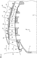
- the figure 2 is a sectional view of a compressor of an axial turbomachine such as that of the figure 1 .
- the compressor can be a low pressure compressor 4.
- the rotor 12 comprises several rows of rotor blades 24, in this case three.
- the low-pressure compressor 4 comprises a plurality of rectifiers, in this case four, which each contain a row of stator vanes 26. Some stator vanes may be adjustable in orientation, also called variable-pitch vanes.
- the rectifiers are associated with the fan 16 or a row of rotor blades to straighten the air flow, so as to convert the speed of the flow pressure, including static pressure.
- the compressor 4 may comprise an outer casing 28.
- the latter may comprise an arcuate wall 30.
- This wall 30 may describe a closed one-piece loop around the axis of rotation 14, or be formed of half-shells, or half -cercles.
- the housing 28, and in particular its wall 30 may be made of an organic matrix composite material.
- the matrix may be reinforced with fibers, possibly in the form of a preform.
- the reinforcement may comprise fibrous folds, for example carbon fiber or glass fiber.
- the stator vanes 26 extend essentially radially from the wall 30, and can be fixed thereto and immobilized by means of pins 32.
- the stator vanes 26 comprise attachment platforms 34, which optionally receive the axes of 32.
- the blades as the platforms may be titanium.
- the stator via its housing 28, receives at least one annular seal 36, possibly an annular seal 36 around each annular row of rotor blades 24. At least one or more or each annular seal 36 may be an abradable seal with an annular layer of abradable material 38.
- the seals are abradable seals 36, they participate in the reduction of leakage by allowing a connection between the vanes 24 and the casing 28. .
- internal ferrules 40 are connected to the inner ends of the stator vanes 26. These ferrules 40 may also receive an abradable seal as described in the present invention, and cooperating with the rotor 12 sealingly.
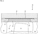
- the figure 3 represents an abradable gasket 36 of a compressor such as that of the figure 2 .
- a wall 34 of casing 28, or support 28 an abradable layer 38 of gasket 36 applied thereto, and a rotor blade end 24 between two stator vanes 26.
- the abradable layer 38 extends from one blade platform 26 to the other, which belongs to a neighboring row disposed upstream or downstream. At least one or each abradable seal may be in contact with the material of the blade platforms, possibly in electrical contact.
- the abradable layer 38 may be applied directly to the wall 30 of the casing 28.
- the seal 36 may comprise an intermediate layer between the support and the abradable layer 38.
- the intermediate layer may be a strip 42, such as a metal sheet. steel, or nickel sheet.
- the strip 42 may be perforated and / or cut. It can be of constant thickness.
- the abradable layer 38 may be thicker than the strip 42.
- the strip 42 can be glued to the wall 30, and / or be maintained thanks to the platforms 34 of the blades 26.
- the upstream and / or downstream edges of the strip 42 are clamped between the platforms 34 and the wall 30.
- the abradable layer 38 has an inner surface 44 in contact with the primary stream 18. Its surface 44 guides and defines the primary stream 18 during its compression. It can be flush with the internal surfaces of the platforms 34.
- the composition of the material forming the abradable layer 38 and therefore the seal 36 may comprise at least two mixed phases, namely a metallic phase and a second phase.
- the second phase can be mineral and / or organic.
- the abradable can be composite; and / or granular; and / or with spaces filled by some of its constituents.
- the second phase can form a lubricant.
- the metal phase mainly comprises aluminum.
- the metal phase of the composition is aluminum-based. That is to say that among the metals of the abradable, the one whose mass is the most important is aluminum.
- the preponderance of aluminum optimizes the mass of the seal 36.
- the metallic phase may also comprise chromium, in a lower weight proportion than aluminum.
- the metal phase may comprise between 20% and 45% of chromium; and between 55% and 80% aluminum.
- Aluminum and chromium may be the only two metals in which each of the masses represents at least 0.10%, or at least 1% of the mass of the composition.
- the metal phase may consist of aluminum and chromium.
- the metal phase may also comprise nickel, especially in lower mass proportion to that of chromium, for example two times lower.
- the metal phase may comprise, by weight, 10% of chromium and / or 5% of nickel; or else, by weight, 30% of chromium and 10% of nickel.
- the metal phase may optionally include iron, copper, zinc, manganese, magnesium, impurities; these components each representing or in all between 1% and 0.1% of the mass of the metal phase.
- the organic material of the second phase of the composition may comprise polymer, such as polyester, polyimide, polyamide-imide, polyether-imide, bismaleimide, fluoroplast, a ketone-based resin, liquid crystal of polymers; or all their possible combinations.
- polymer such as polyester, polyimide, polyamide-imide, polyether-imide, bismaleimide, fluoroplast, a ketone-based resin, liquid crystal of polymers; or all their possible combinations.
- the second phase may also include hexagonal boron nitride, calcium fluoride, molybdenum disulfide, graphite, talc, bentonite, mica; or all their possible combinations. These materials can be considered as mineral materials.
- the second phase may comprise a mixture of at least one mineral material with at least one organic material.
- the mass of the second phase can represent: from 5% up to 50%, or from 15% up to 25%, optionally 20% of the mass of the composition.
- the metal phase can represent the majority of the volume of the abradable layer, thus, the metal phase can form there a matrix receiving the second phase.
- the abradable layer may be formed of grains of metal powders whose inter-grain spaces are filled by the second phase.
- the empty space in the abradable layer is less than 1%, preferably less than 0.1%.
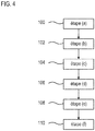
- the figure 4 represents a diagram of a process for producing an abradable axial turbomachine seal as presented in FIG. figures 2 and / or 3.
- the seal can be used on a compressor, particularly low-pressure, as detailed in connection with the figures 1 and / or 2.
- the composition has a metal phase with mainly aluminum, for example in powder form.
- the aluminum can be pure, or in the form of an alloy. The same applies to chrome.
- the composition may also include chromium and optionally a second metal; both in powders.
- the chromium mass is at least 20%, or 21%, or 22%, or 23% of the metal phase.
- the composition of the powder may correspond to the chemical composition of the abradable layer presented above.
- step (f) application 110 At the end of step (f) application 110, at least one or each compound of the composition remains in powder form, or at least one of the compounds has melted, or each compound has melted.
- each type of powder kernel is essentially full.
- Each grain can form a homogeneous material.
- one type of grain is hollow, for example aluminum or chromium grains.
- the composition can be applied to the casing, thus against the arcuate wall, by plasma spraying.
- plasma spraying Such a thermal technique is well known to those skilled in the art, it can be carried out in a manner similar to that disclosed in the document EP 1 010 861 A2 .
- the powder of the second phase can be introduced into the plasma jet downstream of the metal powders.
- Other techniques are possible.
- the composition can be applied to the support by sintering, optionally with prolonged heating. In this alternative, some grains may retain their original forms.
- step (b) supplying 102 stator vanes; (c) providing or manufacturing a strip; (d) placing the strip against the housing, especially against the inner surface of the arcuate wall; (e) fastening 108 of the blades; are entirely optional according to the invention.
- the abradable composition can be applied to a free blade support and / or strip free.
- step (f) application 110 can be performed in a groove formed in the thickness of the arcuate wall; and / or directly on the inner surface of the arcuate wall.
- composition The characteristics defined in relation to the composition can be applied to the joint, and vice versa.
Landscapes
- Engineering & Computer Science (AREA)
- Chemical & Material Sciences (AREA)
- Mechanical Engineering (AREA)
- Plasma & Fusion (AREA)
- Physics & Mathematics (AREA)
- Materials Engineering (AREA)
- Chemical Kinetics & Catalysis (AREA)
- Metallurgy (AREA)
- Organic Chemistry (AREA)
- General Engineering & Computer Science (AREA)
- Structures Of Non-Positive Displacement Pumps (AREA)
- Turbine Rotor Nozzle Sealing (AREA)
- Coating By Spraying Or Casting (AREA)
Applications Claiming Priority (1)
| Application Number | Priority Date | Filing Date | Title |
|---|---|---|---|
| BE2017/5556A BE1025469B1 (fr) | 2017-08-14 | 2017-08-14 | Composition de joint abradable pour compresseur de turbomachine |
Publications (2)
| Publication Number | Publication Date |
|---|---|
| EP3444443A1 true EP3444443A1 (de) | 2019-02-20 |
| EP3444443B1 EP3444443B1 (de) | 2020-07-01 |
Family
ID=59772320
Family Applications (1)
| Application Number | Title | Priority Date | Filing Date |
|---|---|---|---|
| EP18186069.3A Active EP3444443B1 (de) | 2017-08-14 | 2018-07-27 | Zusammensetzung einer anstreifdichtung für den kompressor einer turbomaschine |
Country Status (5)
| Country | Link |
|---|---|
| US (1) | US20190048454A1 (de) |
| EP (1) | EP3444443B1 (de) |
| JP (1) | JP7349778B2 (de) |
| CN (1) | CN109386315B (de) |
| BE (1) | BE1025469B1 (de) |
Cited By (2)
| Publication number | Priority date | Publication date | Assignee | Title |
|---|---|---|---|---|
| WO2024099721A1 (fr) | 2022-11-09 | 2024-05-16 | Safran Aero Boosters | Composition pour joint abradable de turbomachine |
| BE1032648B1 (fr) * | 2024-05-31 | 2026-01-12 | Safran Aero Boosters | Carter de compresseur basse pression d'une turbomachine d'aéronef |
Families Citing this family (7)
| Publication number | Priority date | Publication date | Assignee | Title |
|---|---|---|---|---|
| BE1027280B1 (fr) * | 2019-05-16 | 2020-12-15 | Safran Aero Boosters Sa | Carter de compresseur pour turbomachine |
| CN111155120A (zh) * | 2019-12-31 | 2020-05-15 | 中山市皓祥模具五金有限公司 | 一种耐腐蚀合金件的表面处理方法 |
| FR3107524B1 (fr) * | 2020-02-25 | 2022-12-16 | Safran Aircraft Engines | Revêtement abradable |
| US11674210B2 (en) * | 2020-08-31 | 2023-06-13 | Metal Improvement Company, Llc | Method for making high lubricity abradable material and abradable coating |
| CN112210743A (zh) * | 2020-09-30 | 2021-01-12 | 美图(福建)铝业有限公司 | 一种铝合金型材及其制造方法 |
| US20220307388A1 (en) * | 2021-03-24 | 2022-09-29 | General Electric Company | Hybrid composite components |
| DE102023121106A1 (de) | 2023-08-08 | 2025-02-13 | MTU Aero Engines AG | Leitschaufelanordnung einer Strömungsmaschine und Verfahren zur Montage einer Leitschaufelanordnung |
Citations (3)
| Publication number | Priority date | Publication date | Assignee | Title |
|---|---|---|---|---|
| EP1010861A2 (de) | 1998-12-18 | 2000-06-21 | United Technologies Corporation | Abreibbare Dichtungsschicht und deren Herstellungsweise |
| EP1428600A1 (de) | 2002-12-13 | 2004-06-16 | Snecma Moteurs | Pulverartiges Material für abreibbare Dichtung |
| EP3023511A1 (de) | 2014-11-24 | 2016-05-25 | Techspace Aero S.A. | Zusammensetzung und Abriebdichtung eines Kompressorgehäuses einer axialen Turbomaschine |
Family Cites Families (10)
| Publication number | Priority date | Publication date | Assignee | Title |
|---|---|---|---|---|
| US5196471A (en) * | 1990-11-19 | 1993-03-23 | Sulzer Plasma Technik, Inc. | Thermal spray powders for abradable coatings, abradable coatings containing solid lubricants and methods of fabricating abradable coatings |
| US6102656A (en) * | 1995-09-26 | 2000-08-15 | United Technologies Corporation | Segmented abradable ceramic coating |
| US6254700B1 (en) * | 1999-03-16 | 2001-07-03 | Praxair S.T. Technology, Inc. | Abradable quasicrystalline coating |
| US6533285B2 (en) * | 2001-02-05 | 2003-03-18 | Caterpillar Inc | Abradable coating and method of production |
| US7165946B2 (en) * | 2004-06-21 | 2007-01-23 | Solar Turbine Incorporated | Low-mid turbine temperature abradable coating |
| GB2452515B (en) * | 2007-09-06 | 2009-08-05 | Siemens Ag | Seal coating between rotor blade and rotor disk slot in gas turbine engine |
| US20130177437A1 (en) * | 2012-01-05 | 2013-07-11 | General Electric Company | Processes for coating a turbine rotor and articles thereof |
| EP2623730A1 (de) * | 2012-02-02 | 2013-08-07 | Siemens Aktiengesellschaft | Strömungsmaschinenkomponente mit Teilfuge und Dampfturbine mit der Strömungsmaschinenkomponente |
| CN104087789B (zh) * | 2014-07-28 | 2016-09-28 | 苏州大学 | 用于钛合金表面的自润滑耐磨复合涂层及其制备方法 |
| CN107740094B (zh) * | 2017-09-18 | 2019-12-06 | 苏州大学 | 一种用于机闸上的高温封严涂层及其制备方法 |
-
2017
- 2017-08-14 BE BE2017/5556A patent/BE1025469B1/fr active IP Right Grant
-
2018
- 2018-07-27 EP EP18186069.3A patent/EP3444443B1/de active Active
- 2018-08-02 JP JP2018145687A patent/JP7349778B2/ja active Active
- 2018-08-13 US US16/102,106 patent/US20190048454A1/en not_active Abandoned
- 2018-08-13 CN CN201810914204.4A patent/CN109386315B/zh active Active
Patent Citations (3)
| Publication number | Priority date | Publication date | Assignee | Title |
|---|---|---|---|---|
| EP1010861A2 (de) | 1998-12-18 | 2000-06-21 | United Technologies Corporation | Abreibbare Dichtungsschicht und deren Herstellungsweise |
| EP1428600A1 (de) | 2002-12-13 | 2004-06-16 | Snecma Moteurs | Pulverartiges Material für abreibbare Dichtung |
| EP3023511A1 (de) | 2014-11-24 | 2016-05-25 | Techspace Aero S.A. | Zusammensetzung und Abriebdichtung eines Kompressorgehäuses einer axialen Turbomaschine |
Cited By (4)
| Publication number | Priority date | Publication date | Assignee | Title |
|---|---|---|---|---|
| WO2024099721A1 (fr) | 2022-11-09 | 2024-05-16 | Safran Aero Boosters | Composition pour joint abradable de turbomachine |
| BE1031024A1 (fr) | 2022-11-09 | 2024-06-06 | Safran Aero Boosters | Composition pour joint abradable de turmomachine |
| BE1031024B1 (fr) * | 2022-11-09 | 2024-06-10 | Safran Aero Boosters | Composition pour joint abradable de turmomachine |
| BE1032648B1 (fr) * | 2024-05-31 | 2026-01-12 | Safran Aero Boosters | Carter de compresseur basse pression d'une turbomachine d'aéronef |
Also Published As
| Publication number | Publication date |
|---|---|
| BE1025469A1 (fr) | 2019-03-11 |
| EP3444443B1 (de) | 2020-07-01 |
| BE1025469B1 (fr) | 2019-03-18 |
| JP7349778B2 (ja) | 2023-09-25 |
| CN109386315B (zh) | 2022-08-09 |
| CN109386315A (zh) | 2019-02-26 |
| US20190048454A1 (en) | 2019-02-14 |
| JP2019052637A (ja) | 2019-04-04 |
Similar Documents
| Publication | Publication Date | Title |
|---|---|---|
| EP3444443B1 (de) | Zusammensetzung einer anstreifdichtung für den kompressor einer turbomaschine | |
| EP3023511B1 (de) | Zusammensetzung und Abriebdichtung eines Kompressorgehäuses einer axialen Turbomaschine | |
| EP3064708B1 (de) | Verbundwerkstoffschaufel eines kompressors eines axialen turbotriebwerks mit einem verstäkungsblech und zugehörige turbomachine mit solch eine schaufel. | |
| BE1022481B1 (fr) | Aube a treillis de compresseur de turbomachine axiale | |
| EP3361055B1 (de) | Anordnung einer axialen turbomaschine und verfahren zur regelung von umfangsspalten | |
| EP2801702B1 (de) | Stator-innenring eines turbotriebwerks mit abriebmaterial | |
| EP2896796B1 (de) | Stator einer axialen Strömungsmaschine und zugehörige Strömungsmaschine | |
| EP3095963B1 (de) | Laufradschaufel und deckband eines kompressors eines axialen turbotriebwerks | |
| EP3698050B1 (de) | Turboverdichter-aussengehäuse mit integriertem ölbehälter | |
| EP2977559A1 (de) | Leitschaufel mit im Innenring eines Kompressors einer axialen Strömungsmaschine eingebettetem Drahtgewebe, und zugehörige Strömungsmaschine | |
| JP2009156263A (ja) | ターボ機械要素の製造方法およびその方法で得られる装置 | |
| EP2886804B1 (de) | Dichtungsanordnung für einen Verdicther eines Turbotriebwerks | |
| EP3409902A1 (de) | Abdichtungssystem für kompressor einer strömungsmaschine | |
| WO2021048473A1 (fr) | Fixation d'une virole acoustique a une enveloppé de carter pour une turbomachine d'aéronef | |
| EP3091201A1 (de) | Verbund-trennwandspitze eines kompressors einer axialen turbomaschine | |
| EP3918204A1 (de) | Lüftergehäuse für eine flugzeugturbomaschine | |
| EP3290133B1 (de) | Herstellungsverfahren einer abriebdichtung für strömungsmaschine | |
| EP3382155B1 (de) | Dichtungssystem für eine strömungsmaschine, und zugehörige strömungsmaschine | |
| FR2997470A1 (fr) | Dispositif de fixation par vissage d'un joint a brosse pour l'etancheite d'une enceinte de lubrification de turbomachine. | |
| BE1031024B9 (fr) | Composition pour joint abradable de turbomachine | |
| BE1022808B1 (fr) | Joint abradable de carter de compresseur de turbomachine axiale | |
| FR2978987A1 (fr) | Carter de compresseur haute-pression comportant une paroi interne resistante au feu de titane | |
| BE1023367A1 (fr) | Fixation de virole interne de compresseur de turbomachine axiale |
Legal Events
| Date | Code | Title | Description |
|---|---|---|---|
| PUAI | Public reference made under article 153(3) epc to a published international application that has entered the european phase |
Free format text: ORIGINAL CODE: 0009012 |
|
| STAA | Information on the status of an ep patent application or granted ep patent |
Free format text: STATUS: THE APPLICATION HAS BEEN PUBLISHED |
|
| AK | Designated contracting states |
Kind code of ref document: A1 Designated state(s): AL AT BE BG CH CY CZ DE DK EE ES FI FR GB GR HR HU IE IS IT LI LT LU LV MC MK MT NL NO PL PT RO RS SE SI SK SM TR |
|
| AX | Request for extension of the european patent |
Extension state: BA ME |
|
| STAA | Information on the status of an ep patent application or granted ep patent |
Free format text: STATUS: REQUEST FOR EXAMINATION WAS MADE |
|
| 17P | Request for examination filed |
Effective date: 20190723 |
|
| RBV | Designated contracting states (corrected) |
Designated state(s): AL AT BE BG CH CY CZ DE DK EE ES FI FR GB GR HR HU IE IS IT LI LT LU LV MC MK MT NL NO PL PT RO RS SE SI SK SM TR |
|
| GRAP | Despatch of communication of intention to grant a patent |
Free format text: ORIGINAL CODE: EPIDOSNIGR1 |
|
| STAA | Information on the status of an ep patent application or granted ep patent |
Free format text: STATUS: GRANT OF PATENT IS INTENDED |
|
| INTG | Intention to grant announced |
Effective date: 20200224 |
|
| GRAS | Grant fee paid |
Free format text: ORIGINAL CODE: EPIDOSNIGR3 |
|
| GRAA | (expected) grant |
Free format text: ORIGINAL CODE: 0009210 |
|
| STAA | Information on the status of an ep patent application or granted ep patent |
Free format text: STATUS: THE PATENT HAS BEEN GRANTED |
|
| AK | Designated contracting states |
Kind code of ref document: B1 Designated state(s): AL AT BE BG CH CY CZ DE DK EE ES FI FR GB GR HR HU IE IS IT LI LT LU LV MC MK MT NL NO PL PT RO RS SE SI SK SM TR |
|
| REG | Reference to a national code |
Ref country code: CH Ref legal event code: EP Ref country code: AT Ref legal event code: REF Ref document number: 1286367 Country of ref document: AT Kind code of ref document: T Effective date: 20200715 |
|
| REG | Reference to a national code |
Ref country code: IE Ref legal event code: FG4D Free format text: LANGUAGE OF EP DOCUMENT: FRENCH |
|
| REG | Reference to a national code |
Ref country code: DE Ref legal event code: R096 Ref document number: 602018005671 Country of ref document: DE |
|
| REG | Reference to a national code |
Ref country code: LT Ref legal event code: MG4D |
|
| PG25 | Lapsed in a contracting state [announced via postgrant information from national office to epo] |
Ref country code: BG Free format text: LAPSE BECAUSE OF FAILURE TO SUBMIT A TRANSLATION OF THE DESCRIPTION OR TO PAY THE FEE WITHIN THE PRESCRIBED TIME-LIMIT Effective date: 20201001 |
|
| REG | Reference to a national code |
Ref country code: NL Ref legal event code: MP Effective date: 20200701 |
|
| REG | Reference to a national code |
Ref country code: AT Ref legal event code: MK05 Ref document number: 1286367 Country of ref document: AT Kind code of ref document: T Effective date: 20200701 |
|
| PG25 | Lapsed in a contracting state [announced via postgrant information from national office to epo] |
Ref country code: AT Free format text: LAPSE BECAUSE OF FAILURE TO SUBMIT A TRANSLATION OF THE DESCRIPTION OR TO PAY THE FEE WITHIN THE PRESCRIBED TIME-LIMIT Effective date: 20200701 Ref country code: PT Free format text: LAPSE BECAUSE OF FAILURE TO SUBMIT A TRANSLATION OF THE DESCRIPTION OR TO PAY THE FEE WITHIN THE PRESCRIBED TIME-LIMIT Effective date: 20201102 Ref country code: SE Free format text: LAPSE BECAUSE OF FAILURE TO SUBMIT A TRANSLATION OF THE DESCRIPTION OR TO PAY THE FEE WITHIN THE PRESCRIBED TIME-LIMIT Effective date: 20200701 Ref country code: NO Free format text: LAPSE BECAUSE OF FAILURE TO SUBMIT A TRANSLATION OF THE DESCRIPTION OR TO PAY THE FEE WITHIN THE PRESCRIBED TIME-LIMIT Effective date: 20201001 Ref country code: LT Free format text: LAPSE BECAUSE OF FAILURE TO SUBMIT A TRANSLATION OF THE DESCRIPTION OR TO PAY THE FEE WITHIN THE PRESCRIBED TIME-LIMIT Effective date: 20200701 Ref country code: GR Free format text: LAPSE BECAUSE OF FAILURE TO SUBMIT A TRANSLATION OF THE DESCRIPTION OR TO PAY THE FEE WITHIN THE PRESCRIBED TIME-LIMIT Effective date: 20201002 Ref country code: ES Free format text: LAPSE BECAUSE OF FAILURE TO SUBMIT A TRANSLATION OF THE DESCRIPTION OR TO PAY THE FEE WITHIN THE PRESCRIBED TIME-LIMIT Effective date: 20200701 Ref country code: CZ Free format text: LAPSE BECAUSE OF FAILURE TO SUBMIT A TRANSLATION OF THE DESCRIPTION OR TO PAY THE FEE WITHIN THE PRESCRIBED TIME-LIMIT Effective date: 20200701 Ref country code: FI Free format text: LAPSE BECAUSE OF FAILURE TO SUBMIT A TRANSLATION OF THE DESCRIPTION OR TO PAY THE FEE WITHIN THE PRESCRIBED TIME-LIMIT Effective date: 20200701 Ref country code: HR Free format text: LAPSE BECAUSE OF FAILURE TO SUBMIT A TRANSLATION OF THE DESCRIPTION OR TO PAY THE FEE WITHIN THE PRESCRIBED TIME-LIMIT Effective date: 20200701 |
|
| PG25 | Lapsed in a contracting state [announced via postgrant information from national office to epo] |
Ref country code: LV Free format text: LAPSE BECAUSE OF FAILURE TO SUBMIT A TRANSLATION OF THE DESCRIPTION OR TO PAY THE FEE WITHIN THE PRESCRIBED TIME-LIMIT Effective date: 20200701 Ref country code: RS Free format text: LAPSE BECAUSE OF FAILURE TO SUBMIT A TRANSLATION OF THE DESCRIPTION OR TO PAY THE FEE WITHIN THE PRESCRIBED TIME-LIMIT Effective date: 20200701 Ref country code: PL Free format text: LAPSE BECAUSE OF FAILURE TO SUBMIT A TRANSLATION OF THE DESCRIPTION OR TO PAY THE FEE WITHIN THE PRESCRIBED TIME-LIMIT Effective date: 20200701 Ref country code: IS Free format text: LAPSE BECAUSE OF FAILURE TO SUBMIT A TRANSLATION OF THE DESCRIPTION OR TO PAY THE FEE WITHIN THE PRESCRIBED TIME-LIMIT Effective date: 20201101 |
|
| PG25 | Lapsed in a contracting state [announced via postgrant information from national office to epo] |
Ref country code: NL Free format text: LAPSE BECAUSE OF FAILURE TO SUBMIT A TRANSLATION OF THE DESCRIPTION OR TO PAY THE FEE WITHIN THE PRESCRIBED TIME-LIMIT Effective date: 20200701 Ref country code: MC Free format text: LAPSE BECAUSE OF FAILURE TO SUBMIT A TRANSLATION OF THE DESCRIPTION OR TO PAY THE FEE WITHIN THE PRESCRIBED TIME-LIMIT Effective date: 20200701 |
|
| REG | Reference to a national code |
Ref country code: DE Ref legal event code: R097 Ref document number: 602018005671 Country of ref document: DE |
|
| PG25 | Lapsed in a contracting state [announced via postgrant information from national office to epo] |
Ref country code: LU Free format text: LAPSE BECAUSE OF NON-PAYMENT OF DUE FEES Effective date: 20200727 Ref country code: SM Free format text: LAPSE BECAUSE OF FAILURE TO SUBMIT A TRANSLATION OF THE DESCRIPTION OR TO PAY THE FEE WITHIN THE PRESCRIBED TIME-LIMIT Effective date: 20200701 Ref country code: IT Free format text: LAPSE BECAUSE OF FAILURE TO SUBMIT A TRANSLATION OF THE DESCRIPTION OR TO PAY THE FEE WITHIN THE PRESCRIBED TIME-LIMIT Effective date: 20200701 Ref country code: EE Free format text: LAPSE BECAUSE OF FAILURE TO SUBMIT A TRANSLATION OF THE DESCRIPTION OR TO PAY THE FEE WITHIN THE PRESCRIBED TIME-LIMIT Effective date: 20200701 Ref country code: RO Free format text: LAPSE BECAUSE OF FAILURE TO SUBMIT A TRANSLATION OF THE DESCRIPTION OR TO PAY THE FEE WITHIN THE PRESCRIBED TIME-LIMIT Effective date: 20200701 Ref country code: DK Free format text: LAPSE BECAUSE OF FAILURE TO SUBMIT A TRANSLATION OF THE DESCRIPTION OR TO PAY THE FEE WITHIN THE PRESCRIBED TIME-LIMIT Effective date: 20200701 |
|
| PLBE | No opposition filed within time limit |
Free format text: ORIGINAL CODE: 0009261 |
|
| STAA | Information on the status of an ep patent application or granted ep patent |
Free format text: STATUS: NO OPPOSITION FILED WITHIN TIME LIMIT |
|
| PG25 | Lapsed in a contracting state [announced via postgrant information from national office to epo] |
Ref country code: AL Free format text: LAPSE BECAUSE OF FAILURE TO SUBMIT A TRANSLATION OF THE DESCRIPTION OR TO PAY THE FEE WITHIN THE PRESCRIBED TIME-LIMIT Effective date: 20200701 |
|
| 26N | No opposition filed |
Effective date: 20210406 |
|
| PG25 | Lapsed in a contracting state [announced via postgrant information from national office to epo] |
Ref country code: SK Free format text: LAPSE BECAUSE OF FAILURE TO SUBMIT A TRANSLATION OF THE DESCRIPTION OR TO PAY THE FEE WITHIN THE PRESCRIBED TIME-LIMIT Effective date: 20200701 |
|
| PG25 | Lapsed in a contracting state [announced via postgrant information from national office to epo] |
Ref country code: SI Free format text: LAPSE BECAUSE OF FAILURE TO SUBMIT A TRANSLATION OF THE DESCRIPTION OR TO PAY THE FEE WITHIN THE PRESCRIBED TIME-LIMIT Effective date: 20200701 Ref country code: IE Free format text: LAPSE BECAUSE OF NON-PAYMENT OF DUE FEES Effective date: 20200727 |
|
| REG | Reference to a national code |
Ref country code: CH Ref legal event code: PL |
|
| PG25 | Lapsed in a contracting state [announced via postgrant information from national office to epo] |
Ref country code: LI Free format text: LAPSE BECAUSE OF NON-PAYMENT OF DUE FEES Effective date: 20210731 Ref country code: CH Free format text: LAPSE BECAUSE OF NON-PAYMENT OF DUE FEES Effective date: 20210731 |
|
| PG25 | Lapsed in a contracting state [announced via postgrant information from national office to epo] |
Ref country code: TR Free format text: LAPSE BECAUSE OF FAILURE TO SUBMIT A TRANSLATION OF THE DESCRIPTION OR TO PAY THE FEE WITHIN THE PRESCRIBED TIME-LIMIT Effective date: 20200701 Ref country code: MT Free format text: LAPSE BECAUSE OF FAILURE TO SUBMIT A TRANSLATION OF THE DESCRIPTION OR TO PAY THE FEE WITHIN THE PRESCRIBED TIME-LIMIT Effective date: 20200701 Ref country code: CY Free format text: LAPSE BECAUSE OF FAILURE TO SUBMIT A TRANSLATION OF THE DESCRIPTION OR TO PAY THE FEE WITHIN THE PRESCRIBED TIME-LIMIT Effective date: 20200701 |
|
| PG25 | Lapsed in a contracting state [announced via postgrant information from national office to epo] |
Ref country code: MK Free format text: LAPSE BECAUSE OF FAILURE TO SUBMIT A TRANSLATION OF THE DESCRIPTION OR TO PAY THE FEE WITHIN THE PRESCRIBED TIME-LIMIT Effective date: 20200701 |
|
| PGFP | Annual fee paid to national office [announced via postgrant information from national office to epo] |
Ref country code: DE Payment date: 20250722 Year of fee payment: 8 |
|
| PGFP | Annual fee paid to national office [announced via postgrant information from national office to epo] |
Ref country code: BE Payment date: 20250722 Year of fee payment: 8 Ref country code: GB Payment date: 20250724 Year of fee payment: 8 |
|
| PGFP | Annual fee paid to national office [announced via postgrant information from national office to epo] |
Ref country code: FR Payment date: 20250722 Year of fee payment: 8 |