EP3444443B1 - Composition de joint abradable pour compresseur de turbomachine - Google Patents
Composition de joint abradable pour compresseur de turbomachine Download PDFInfo
- Publication number
- EP3444443B1 EP3444443B1 EP18186069.3A EP18186069A EP3444443B1 EP 3444443 B1 EP3444443 B1 EP 3444443B1 EP 18186069 A EP18186069 A EP 18186069A EP 3444443 B1 EP3444443 B1 EP 3444443B1
- Authority
- EP
- European Patent Office
- Prior art keywords
- composition
- phase
- abradable
- turbomachine
- compressor
- Prior art date
- Legal status (The legal status is an assumption and is not a legal conclusion. Google has not performed a legal analysis and makes no representation as to the accuracy of the status listed.)
- Active
Links
Images


Classifications
-
- C—CHEMISTRY; METALLURGY
- C23—COATING METALLIC MATERIAL; COATING MATERIAL WITH METALLIC MATERIAL; CHEMICAL SURFACE TREATMENT; DIFFUSION TREATMENT OF METALLIC MATERIAL; COATING BY VACUUM EVAPORATION, BY SPUTTERING, BY ION IMPLANTATION OR BY CHEMICAL VAPOUR DEPOSITION, IN GENERAL; INHIBITING CORROSION OF METALLIC MATERIAL OR INCRUSTATION IN GENERAL
- C23C—COATING METALLIC MATERIAL; COATING MATERIAL WITH METALLIC MATERIAL; SURFACE TREATMENT OF METALLIC MATERIAL BY DIFFUSION INTO THE SURFACE, BY CHEMICAL CONVERSION OR SUBSTITUTION; COATING BY VACUUM EVAPORATION, BY SPUTTERING, BY ION IMPLANTATION OR BY CHEMICAL VAPOUR DEPOSITION, IN GENERAL
- C23C4/00—Coating by spraying the coating material in the molten state, e.g. by flame, plasma or electric discharge
- C23C4/04—Coating by spraying the coating material in the molten state, e.g. by flame, plasma or electric discharge characterised by the coating material
- C23C4/06—Metallic material
-
- F—MECHANICAL ENGINEERING; LIGHTING; HEATING; WEAPONS; BLASTING
- F01—MACHINES OR ENGINES IN GENERAL; ENGINE PLANTS IN GENERAL; STEAM ENGINES
- F01D—NON-POSITIVE DISPLACEMENT MACHINES OR ENGINES, e.g. STEAM TURBINES
- F01D11/00—Preventing or minimising internal leakage of working-fluid, e.g. between stages
- F01D11/08—Preventing or minimising internal leakage of working-fluid, e.g. between stages for sealing space between rotor blade tips and stator
- F01D11/12—Preventing or minimising internal leakage of working-fluid, e.g. between stages for sealing space between rotor blade tips and stator using a rubstrip, e.g. erodible. deformable or resiliently-biased part
- F01D11/122—Preventing or minimising internal leakage of working-fluid, e.g. between stages for sealing space between rotor blade tips and stator using a rubstrip, e.g. erodible. deformable or resiliently-biased part with erodable or abradable material
- F01D11/125—Preventing or minimising internal leakage of working-fluid, e.g. between stages for sealing space between rotor blade tips and stator using a rubstrip, e.g. erodible. deformable or resiliently-biased part with erodable or abradable material with a reinforcing structure
-
- C—CHEMISTRY; METALLURGY
- C23—COATING METALLIC MATERIAL; COATING MATERIAL WITH METALLIC MATERIAL; CHEMICAL SURFACE TREATMENT; DIFFUSION TREATMENT OF METALLIC MATERIAL; COATING BY VACUUM EVAPORATION, BY SPUTTERING, BY ION IMPLANTATION OR BY CHEMICAL VAPOUR DEPOSITION, IN GENERAL; INHIBITING CORROSION OF METALLIC MATERIAL OR INCRUSTATION IN GENERAL
- C23C—COATING METALLIC MATERIAL; COATING MATERIAL WITH METALLIC MATERIAL; SURFACE TREATMENT OF METALLIC MATERIAL BY DIFFUSION INTO THE SURFACE, BY CHEMICAL CONVERSION OR SUBSTITUTION; COATING BY VACUUM EVAPORATION, BY SPUTTERING, BY ION IMPLANTATION OR BY CHEMICAL VAPOUR DEPOSITION, IN GENERAL
- C23C4/00—Coating by spraying the coating material in the molten state, e.g. by flame, plasma or electric discharge
- C23C4/04—Coating by spraying the coating material in the molten state, e.g. by flame, plasma or electric discharge characterised by the coating material
-
- C—CHEMISTRY; METALLURGY
- C23—COATING METALLIC MATERIAL; COATING MATERIAL WITH METALLIC MATERIAL; CHEMICAL SURFACE TREATMENT; DIFFUSION TREATMENT OF METALLIC MATERIAL; COATING BY VACUUM EVAPORATION, BY SPUTTERING, BY ION IMPLANTATION OR BY CHEMICAL VAPOUR DEPOSITION, IN GENERAL; INHIBITING CORROSION OF METALLIC MATERIAL OR INCRUSTATION IN GENERAL
- C23C—COATING METALLIC MATERIAL; COATING MATERIAL WITH METALLIC MATERIAL; SURFACE TREATMENT OF METALLIC MATERIAL BY DIFFUSION INTO THE SURFACE, BY CHEMICAL CONVERSION OR SUBSTITUTION; COATING BY VACUUM EVAPORATION, BY SPUTTERING, BY ION IMPLANTATION OR BY CHEMICAL VAPOUR DEPOSITION, IN GENERAL
- C23C4/00—Coating by spraying the coating material in the molten state, e.g. by flame, plasma or electric discharge
- C23C4/12—Coating by spraying the coating material in the molten state, e.g. by flame, plasma or electric discharge characterised by the method of spraying
- C23C4/134—Plasma spraying
-
- F—MECHANICAL ENGINEERING; LIGHTING; HEATING; WEAPONS; BLASTING
- F01—MACHINES OR ENGINES IN GENERAL; ENGINE PLANTS IN GENERAL; STEAM ENGINES
- F01D—NON-POSITIVE DISPLACEMENT MACHINES OR ENGINES, e.g. STEAM TURBINES
- F01D11/00—Preventing or minimising internal leakage of working-fluid, e.g. between stages
- F01D11/08—Preventing or minimising internal leakage of working-fluid, e.g. between stages for sealing space between rotor blade tips and stator
- F01D11/12—Preventing or minimising internal leakage of working-fluid, e.g. between stages for sealing space between rotor blade tips and stator using a rubstrip, e.g. erodible. deformable or resiliently-biased part
- F01D11/122—Preventing or minimising internal leakage of working-fluid, e.g. between stages for sealing space between rotor blade tips and stator using a rubstrip, e.g. erodible. deformable or resiliently-biased part with erodable or abradable material
-
- F—MECHANICAL ENGINEERING; LIGHTING; HEATING; WEAPONS; BLASTING
- F01—MACHINES OR ENGINES IN GENERAL; ENGINE PLANTS IN GENERAL; STEAM ENGINES
- F01D—NON-POSITIVE DISPLACEMENT MACHINES OR ENGINES, e.g. STEAM TURBINES
- F01D25/00—Component parts, details, or accessories, not provided for in, or of interest apart from, other groups
- F01D25/005—Selecting particular materials
-
- F—MECHANICAL ENGINEERING; LIGHTING; HEATING; WEAPONS; BLASTING
- F05—INDEXING SCHEMES RELATING TO ENGINES OR PUMPS IN VARIOUS SUBCLASSES OF CLASSES F01-F04
- F05D—INDEXING SCHEME FOR ASPECTS RELATING TO NON-POSITIVE-DISPLACEMENT MACHINES OR ENGINES, GAS-TURBINES OR JET-PROPULSION PLANTS
- F05D2220/00—Application
- F05D2220/30—Application in turbines
- F05D2220/32—Application in turbines in gas turbines
- F05D2220/323—Application in turbines in gas turbines for aircraft propulsion, e.g. jet engines
-
- F—MECHANICAL ENGINEERING; LIGHTING; HEATING; WEAPONS; BLASTING
- F05—INDEXING SCHEMES RELATING TO ENGINES OR PUMPS IN VARIOUS SUBCLASSES OF CLASSES F01-F04
- F05D—INDEXING SCHEME FOR ASPECTS RELATING TO NON-POSITIVE-DISPLACEMENT MACHINES OR ENGINES, GAS-TURBINES OR JET-PROPULSION PLANTS
- F05D2230/00—Manufacture
- F05D2230/30—Manufacture with deposition of material
- F05D2230/31—Layer deposition
- F05D2230/312—Layer deposition by plasma spraying
-
- F—MECHANICAL ENGINEERING; LIGHTING; HEATING; WEAPONS; BLASTING
- F05—INDEXING SCHEMES RELATING TO ENGINES OR PUMPS IN VARIOUS SUBCLASSES OF CLASSES F01-F04
- F05D—INDEXING SCHEME FOR ASPECTS RELATING TO NON-POSITIVE-DISPLACEMENT MACHINES OR ENGINES, GAS-TURBINES OR JET-PROPULSION PLANTS
- F05D2240/00—Components
- F05D2240/10—Stators
- F05D2240/11—Shroud seal segments
-
- F—MECHANICAL ENGINEERING; LIGHTING; HEATING; WEAPONS; BLASTING
- F05—INDEXING SCHEMES RELATING TO ENGINES OR PUMPS IN VARIOUS SUBCLASSES OF CLASSES F01-F04
- F05D—INDEXING SCHEME FOR ASPECTS RELATING TO NON-POSITIVE-DISPLACEMENT MACHINES OR ENGINES, GAS-TURBINES OR JET-PROPULSION PLANTS
- F05D2240/00—Components
- F05D2240/55—Seals
-
- F—MECHANICAL ENGINEERING; LIGHTING; HEATING; WEAPONS; BLASTING
- F05—INDEXING SCHEMES RELATING TO ENGINES OR PUMPS IN VARIOUS SUBCLASSES OF CLASSES F01-F04
- F05D—INDEXING SCHEME FOR ASPECTS RELATING TO NON-POSITIVE-DISPLACEMENT MACHINES OR ENGINES, GAS-TURBINES OR JET-PROPULSION PLANTS
- F05D2300/00—Materials; Properties thereof
- F05D2300/10—Metals, alloys or intermetallic compounds
- F05D2300/13—Refractory metals, i.e. Ti, V, Cr, Zr, Nb, Mo, Hf, Ta, W
- F05D2300/132—Chromium
-
- F—MECHANICAL ENGINEERING; LIGHTING; HEATING; WEAPONS; BLASTING
- F05—INDEXING SCHEMES RELATING TO ENGINES OR PUMPS IN VARIOUS SUBCLASSES OF CLASSES F01-F04
- F05D—INDEXING SCHEME FOR ASPECTS RELATING TO NON-POSITIVE-DISPLACEMENT MACHINES OR ENGINES, GAS-TURBINES OR JET-PROPULSION PLANTS
- F05D2300/00—Materials; Properties thereof
- F05D2300/10—Metals, alloys or intermetallic compounds
- F05D2300/17—Alloys
- F05D2300/173—Aluminium alloys, e.g. AlCuMgPb
-
- F—MECHANICAL ENGINEERING; LIGHTING; HEATING; WEAPONS; BLASTING
- F05—INDEXING SCHEMES RELATING TO ENGINES OR PUMPS IN VARIOUS SUBCLASSES OF CLASSES F01-F04
- F05D—INDEXING SCHEME FOR ASPECTS RELATING TO NON-POSITIVE-DISPLACEMENT MACHINES OR ENGINES, GAS-TURBINES OR JET-PROPULSION PLANTS
- F05D2300/00—Materials; Properties thereof
- F05D2300/20—Oxide or non-oxide ceramics
- F05D2300/22—Non-oxide ceramics
- F05D2300/228—Nitrides
- F05D2300/2282—Nitrides of boron
-
- F—MECHANICAL ENGINEERING; LIGHTING; HEATING; WEAPONS; BLASTING
- F05—INDEXING SCHEMES RELATING TO ENGINES OR PUMPS IN VARIOUS SUBCLASSES OF CLASSES F01-F04
- F05D—INDEXING SCHEME FOR ASPECTS RELATING TO NON-POSITIVE-DISPLACEMENT MACHINES OR ENGINES, GAS-TURBINES OR JET-PROPULSION PLANTS
- F05D2300/00—Materials; Properties thereof
- F05D2300/60—Properties or characteristics given to material by treatment or manufacturing
- F05D2300/603—Composites; e.g. fibre-reinforced
- F05D2300/6032—Metal matrix composites [MMC]
Definitions
- the invention relates to the field of turbomachine sealing by abradable two-phase seal.
- the invention also provides a method of producing an abradable seal.
- the invention also relates to a compressor and an axial turbomachine, in particular an aircraft turbojet or an aircraft turboprop.
- the document EP3023511A1 discloses a composition for abradable gasket of a turbomachine, the composition comprising an aluminum base, nickel powder, polyester powder. It also teaches an external low-pressure compressor housing for an axial turbomachine with an abradable seal surrounding an annular row of rotor blades.
- the joint comprises a rounded support covered with a layer of abradable material comprising a metallic phase mainly of aluminum, and with nickel in a lesser proportion.
- the abradable material further comprises 25% and 55% of additive, such as polyester, methyl methacrylate, hexagonal boron nitride, calcium fluoride.
- the support is segmented, and forms an external casing organic matrix composite of the compressor. However, the characteristics of such a seal can be improved. Furthermore, the application of the seal remains complex.
- EP 1,428,600 describes an abradable with an organic / mineral phase and a metallic aluminum phase. The particular mechanical characteristics of such a seal can be improved.
- the invention aims to solve at least one of the problems posed by the prior art. More specifically, the invention aims to optimize the friable nature of the joint. The invention also aims to provide a simple, resistant, light, economical, reliable, easy to produce, convenient maintenance, easy inspection, and performance improving solution.
- the subject of the invention is a composition according to claim 1.
- the subject of the invention is a composition for an abradable gasket for a turbomachine, in particular in powder form, said gasket being able to crumble in the event of contact with a rotor of said turbomachine, the composition comprising : a metallic phase with a majority by weight of aluminum, a second phase comprising an inorganic material and / or an organic material; remarkable in that the metallic phase represents between 80% and 90% of the mass of the composition, and / or represents at least: 81%, or 82% or 83% of the mass of the composition.
- the subject of the invention is a composition for an abradable gasket for a turbomachine, in particular in powder form, said gasket being able to crumble in the event of contact with a rotor of said turbomachine, the composition comprising : a metallic phase with a majority by weight of aluminum, a second phase comprising an inorganic material and / or an organic material; remarkable in that the mineral material represents: from 10% to 45%, or from 10% to 25% of the mass of the composition.
- the invention also relates to a composition for an abradable gasket for a turbomachine, in particular in powder form, said gasket being able to crumble in the event of contact with a rotor of said turbomachine, the composition comprising: a metallic phase with a majority by weight of aluminum, a second phase comprising an inorganic material and / or an organic material; remarkable in that the organic material represents: from 10% to 45%, or from 10% to 25% of the mass of the composition.
- the invention also relates to a composition for an abradable gasket for a turbomachine, in particular in powder form, said gasket being able to crumble in the event of contact with a rotor of said turbomachine, the composition comprising: a metallic phase with a majority of aluminum by mass, a second phase; remarkable in that the second phase comprises at least one of the following materials: polyimide, polyamide-imide, polyether-imide, bismaleimide, fluoroplastic, a ketone-based resin, polymer liquid crystals, disulfide of molybdenum, graphite, talc, bentonite, mica; or any workable combination.
- the invention also relates to a turbomachine compressor, in particular a low-pressure turbomachine compressor, comprising a rotor with rotor blades and an abradable seal cooperating in leaktight manner with said rotor blades, remarkable in that the abradable seal comprises a composition in accordance with the invention.
- the invention also relates to a turbomachine, in particular a turbojet engine, comprising an abradable seal, remarkable in that the composition of the abradable seal is in accordance with the invention, the turbomachine optionally comprises a compressor in accordance with the invention.
- the invention also relates to a method for producing an abradable gasket for a turbomachine, in particular a turbojet, the gasket having an arcuate wall and an abradable composition applied against the arcuate wall, the method comprising the following steps: (a) providing or making an arcuate wall; (f) application by thermal spraying of an abradable seal composition against the arcuate wall, said composition comprising a majority of aluminum in a metallic phase, and a second phase; remarkable in that in step (f) application, the metallic phase also comprises nickel, optionally at the start and / or at the end of step (f) application the composition is in accordance with the invention.
- the composition is applied by plasma spraying.
- each object of the invention is also applicable to the other objects of the invention.
- Each object of the invention can be combined with the other objects, and the objects of the invention can also be combined with the embodiments of the description, which in addition can be combined with one another, according to all possible technical combinations, unless the opposite is not explicitly mentioned.
- the presence of chromium in the abradable composition provides better anchoring on a support.
- cohesion with the metal strip is improved, in particular bonded to a composite casing with an organic matrix.
- the brittle behavior of the abradable which results from it after plasma spraying increases. This is notably due to a better mixing of the metal portion and the second portion.
- Each of them forms grains of reduced size compared to the state of the art. The geometry and the surfaces of the grains eventually show better interpenetration.
- the terms “internal” and “external” refer to a positioning relative to the axis of rotation of an axial turbomachine.
- the axial direction corresponds to the direction along the axis of rotation of the turbomachine.
- the radial direction is perpendicular to the axis of rotation. Upstream and downstream are in reference to the main flow direction of the flow in the turbomachine.
- abradable material is meant a material capable of crumbling in contact with a rotor element of a turbomachine. This material may be suitable for concentrating wear and deformation therein while preserving the integrity of the rotor.
- the figure 1 represents in a simplified manner an axial turbomachine.
- the turbojet engine 2 comprises a first level of compression, called a low-pressure compressor 4, a second level of compression, called a high-pressure compressor 6, a combustion chamber 8 and one or more levels of turbines 10.
- a first level of compression called a low-pressure compressor 4
- a second level of compression called a high-pressure compressor 6
- a combustion chamber 8 and one or more levels of turbines 10.
- the mechanical power from the turbine 10 transmitted via the central shaft to the rotor 12 sets in motion the two compressors 4 and 6.
- the latter comprise several rows of rotor blades associated with rows of stator blades.
- the rotation of the rotor around its axis of rotation 14 thus makes it possible to generate an air flow and to compress it progressively until the inlet of the combustion chamber 8.
- An inlet fan commonly designated as a fan or blower 16 is coupled to the rotor 12 and generates an air flow which is divided into a primary flow 18 passing through the various aforementioned levels of the turbomachine, and into a secondary flow 20 passing through an annular duct. (partially shown) along the machine to then join the primary flow at the turbine outlet.
- the secondary flow can be accelerated so as to generate a thrust reaction necessary for the flight of an aircraft.
- the primary 18 and secondary 20 flows are annular coaxial flows and fitted one inside the other. They are channeled through the casing of the turbomachine and / or of the ferrules.
- the casing has cylindrical walls 21 which can be internal and external.
- the figure 2 is a sectional view of a compressor of an axial turbomachine such as that of the figure 1 .
- the compressor can be a low pressure compressor 4.
- a portion of the fan 16 and the separation nozzle 22 for the primary flow 18 and the secondary flow 20 can be observed there.
- the rotor 12 comprises several rows of rotor blades 24, in this case three.
- the low-pressure compressor 4 comprises several rectifiers, in this case four, which each contain a row of stator vanes 26. Some stator vanes can have an adjustable orientation, also called variable pitch vanes.
- the rectifiers are associated with the fan 16 or with a row of rotor blades to straighten the air flow, so as to convert the speed of the flow into pressure, in particular into static pressure.
- the compressor 4 may comprise an external casing 28. This may include an arcuate wall 30. This wall 30 may describe a closed monobloc loop around the axis of rotation 14, or be formed of half-shells, or even of half - circles.
- the casing 28, and in particular its wall 30 can be made of a composite material with an organic matrix.
- the matrix can be reinforced with fibers, possibly in the form of a preform.
- the reinforcement may include fibrous plies, for example with carbon fibers or glass fibers.
- the stator vanes 26 extend essentially radially from the wall 30, and can be fixed and immobilized therein using pins 32.
- the stator vanes 26 comprise fixing platforms 34, which optionally receive the axes of fixing 32. Both the blades and the platforms can be made of titanium.
- the stator via its housing 28, receives at least one annular seal 36, optionally an annular seal 36 around each annular row of rotor blades 24.
- At least one or more or each annular seal 36 can be an abradable seal with an annular layer of abradable material 38.
- the seals are abradable seal 36, they participate in the reduction of leaks by allowing a bringing together between the blades 24 and the casing 28. .
- internal ferrules 40 are connected to the internal ends of the stator vanes 26. These ferrules 40 can also receive an abradable seal as described in the present invention, and cooperating with the rotor 12 in a sealed manner.
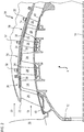
- the figure 3 shows an abradable compressor seal 36 such as that of the figure 2 .
- an abradable compressor seal 36 such as that of the figure 2 .
- a wall 34 of housing 28, or support 28 an abradable layer 38 of seal 36 which is applied thereto, and an end of rotor blade 24 between two stator blades 26.
- the abradable layer 38 extends from a platform 34 of blade 26 to the other, which belongs to a neighboring row arranged upstream or downstream. At least one or each abradable seal may be in contact with the material of the blade platforms, possibly in electrical contact.
- the abradable layer 38 can be applied to the same wall 30 of the casing 28.
- the seal 36 can comprise an intermediate layer between the support and the abradable layer 38.
- the intermediate layer can be a strip 42, such as a sheet of metal. steel, or a sheet of nickel.
- the strip 42 can be perforated and / or cut. It can be of constant thickness.
- the abradable layer 38 can be thicker than the strip 42.
- the strip 42 can be glued to the wall 30, and / or be maintained thanks to the platforms 34 of the blades 26.
- the upstream and / or downstream edges of the strip 42 are pinched between the platforms 34 and the wall 30.
- the abradable layer 38 has an internal surface 44 in contact with the primary flow 18. Its surface 44 guides and delimits the primary flow 18 during its compression. It can be flush with the internal surfaces of the platforms 34.
- the composition of the material forming the abradable layer 38 and therefore the seal 36 can comprise at least two mixed phases, namely a metallic phase and a second phase.
- the second phase can be mineral and / or organic.
- the abradable can be composite; and / or granular; and / or with spaces filled with some of its constituents.
- the second phase can form a lubricant.
- the metallic phase mainly comprises aluminum.
- the metallic phase of the composition is aluminum based. That is to say that among the metals of the abradable, the one whose mass is the most important is aluminum.
- the preponderance of aluminum optimizes the mass of the seal 36.
- the metallic phase may also include chromium, in a mass proportion lower than that of aluminum.
- the metallic phase can comprise between 20% and 45% of chromium; and between 55% and 80% aluminum.
- Aluminum and chromium can be the only two metals, each of whose masses represents at least 0.10%, or at least 1% of the mass of the composition.
- the metallic phase can consist of aluminum and chromium.
- the metallic phase can also comprise nickel, in particular in a mass proportion lower than that of chromium, for example twice lower.
- the metallic phase can comprise, by mass, 10% of chromium and / or 5% of nickel; or, by mass, 30% chromium and 10% nickel.
- the metallic phase may optionally include iron, copper, zinc, manganese, magnesium, impurities; these components representing each or in all between 1% and 0.1% of the mass of the metallic phase.
- the organic material of the second phase of the composition can comprise polymer, such as polyester, polyimide, polyamide-imide, polyether-imide, bismaleimide, fluoroplastic, a ketone-based resin, liquid crystals of polymers; or all of their possible combinations.
- polymer such as polyester, polyimide, polyamide-imide, polyether-imide, bismaleimide, fluoroplastic, a ketone-based resin, liquid crystals of polymers; or all of their possible combinations.
- the second phase can also include hexagonal boron nitride, calcium fluoride, molybdenum disulfide, graphite, talc, bentonite, mica; or all of their possible combinations. These materials can be considered as mineral materials.
- the second phase can comprise a mixture of at least one mineral material with at least one organic material.
- the mass of the second phase can represent: from 5% to 50%, or from 15% to 25%, possibly 20% of the mass of the composition.
- the metallic phase can represent the majority of the volume of the abradable layer, thus, the metallic phase can form there a matrix receiving the second phase.
- the abradable layer can be formed of grains of metal powders whose inter-grain spaces are filled by the second phase.
- the void space in the abradable layer is less than 1%, preferably less than 0.1%.
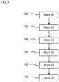
- the figure 4 represents a diagram of a process for producing an abradable seal for an axial turbomachine as presented in figures 2 and / or 3.
- the seal can be used on a compressor, in particular low-pressure, as detailed in relation to the figures 1 and / or 2.
- the composition has a metallic phase with mainly aluminum, for example in the form of a powder.
- Aluminum can be pure, or in the form of an alloy. The same applies to chromium.
- the composition can also comprise chromium and optionally a second metal; both in powders.
- the mass of chromium represents at least: 20%, or 21%, or 22%, or 23% of the metallic phase.
- the composition of the powder can correspond to the chemical composition of the abradable layer presented above.
- step (f) application 110 At the end of step (f) application 110, at least one or each compound of the composition remains in powder form, or at least one of the compounds has melted, or each compound has melted.
- each type of grain of powder is essentially full.
- Each grain can form a homogeneous material.
- one type of grain is hollow, for example aluminum or chromium grains.
- the composition can be applied to the casing, therefore against the arcuate wall, by plasma spraying.
- plasma spraying Such a thermal technique is well known to those skilled in the art, it can be carried out in a similar manner to that disclosed in the document EP 1 010 861 A2 .
- the powder of the second phase can be introduced into the plasma jet downstream of the metal powders.
- Other techniques are possible.
- the composition can be applied to the support by sintering, optionally with prolonged heating. In this alternative, some grains can keep their original shapes.
- the stages: (b) supply 102 of stator vanes; (c) supply or manufacture 104 of a strip; (d) placing the strip 106 against the casing, in particular against the internal surface of the arcuate wall; (e) fixing 108 of the blades; are entirely optional according to the invention.
- the abradable composition can be applied on a support free of blades and / or free of strip.
- step (f) application 110 can be carried out in a groove formed in the thickness of the arcuate wall; and / or directly on the internal surface of the arcuate wall.
- composition can apply to the joint, and vice versa.
Landscapes
- Engineering & Computer Science (AREA)
- Chemical & Material Sciences (AREA)
- Mechanical Engineering (AREA)
- Physics & Mathematics (AREA)
- Plasma & Fusion (AREA)
- Materials Engineering (AREA)
- Chemical Kinetics & Catalysis (AREA)
- Metallurgy (AREA)
- Organic Chemistry (AREA)
- General Engineering & Computer Science (AREA)
- Structures Of Non-Positive Displacement Pumps (AREA)
- Turbine Rotor Nozzle Sealing (AREA)
- Coating By Spraying Or Casting (AREA)
Description
- L'invention se rapporte au domaine de l'étanchéité de turbomachine par joint abradable à deux phases. L'invention propose également un procédé de réalisation d'un joint abradable. L'invention a également trait à un compresseur et à une turbomachine axiale, notamment un turboréacteur d'avion ou un turbopropulseur d'aéronef.
- Les jeux mécaniques entre les têtes d'aubes rotoriques et le carter les entourant impliquent des fuites limitant les performances d'un compresseur de turbomachine. Afin de réduire ces fuites, il est impératif de rapprocher les aubes du carter tout en conservant une marge de sécurité. En effet, en cas de contact les aubes comme le carter peuvent s'endommager, et mettre en péril la sécurité de fonctionnement de la turbomachine. Ces cas de figure restent monnaie courante en raison des vibrations, des ingestions, de la force centrifuge, de la dilatation, et des désaxages du rotor notamment. Dès lors, ajouter une couche de matériau abradable à l'interface entre le carter et les aubes permet de maîtriser l'endommagement en cas de contact puisque la dégradation est concentrée dans la matière du joint qui s'effrite.
- Le document
EP3023511A1 divulgue une composition pour joint abradable de turbomachine, la composition comprenant une base aluminium, de la poudre de nickel, de la poudre de polyester. Il enseigne par ailleurs un carter externe de compresseur-basse pression de turbomachine axiale avec un joint abradable entourant une rangée annulaire d'aubes rotoriques. Le joint comprend un support arrondi recouvert d'une couche de matériau abradable comportant une phase métallique principalement en l'aluminium, et avec du nickel en moindre proportion. L'abradable comporte en outre de 25% et 55% d'additif, tel du polyester, du méthacrylate de méthyle, du nitrure de bore hexagonal, du fluorure de calcium. Le support est segmenté, et forme un carter externe composite à matrice organique du compresseur. Or, les caractéristiques d'un tel joint sont perfectibles. Par ailleurs, l'application du joint reste complexe. - Le document
EP 1 428 600 décrit un abradable avec une phase organique/minérale et une phase métallique d'aluminium. Les caractéristiques notamment mécaniques d'un tel joint sont perfectibles. - L'invention a pour objectif de résoudre au moins un des problèmes posés par l'art antérieur. Plus précisément, l'invention a pour objectif d'optimiser le caractère friable du joint. L'invention a également pour objectif de proposer une solution simple, résistante, légère, économique, fiable, facile à produire, commode d'entretien, d'inspection aisée, et améliorant le rendement.
- L'invention a pour objet une composition selon la revendication 1.
- Selon des modes avantageux de l'invention, la composition peut comprendre une ou plusieurs des caractéristiques suivantes, prises isolément ou selon toutes les combinaisons techniques possibles :
- La phase métallique comprend en masse de 20% jusqu'à 45% de chrome.
- Le matériau polymère comprend du polyester et le matériau organique comprend nitrure de bore hexagonal.
- La phase métallique représente de 50% à 90% de la masse de la composition.
- La phase métallique représente de 82% à 90% de la masse de la composition.
- La deuxième phase représente de 10% à 50% de la masse de la composition.
- La deuxième phase représente de 10% à 25% de la masse de la composition.
- La deuxième phase comprend au moins un des matériaux suivant : le polyimide, le polyamide-imide, le polyéther-imide, le bismaléimide, du fluoroplastique, une résine à base de cétone, des cristaux liquides de polymères ; ou toutes leurs combinaisons.
- La deuxième phase comprend au moins un des matériaux suivant : le disulfure de molybdène, le graphite, le talc, la bentonite, le mica ; ou toutes leurs combinaisons.
- Selon un autre mode de réalisation, l'invention a pour objet une composition pour joint d'étanchéité abradable de turbomachine, notamment en poudre, ledit joint étant apte à s'effriter en cas de contact avec un rotor de ladite turbomachine, la composition comprenant : une phase métallique avec une majorité massique d'aluminium, une deuxième phase comprenant un matériau minéral et/ou un matériau organique; remarquable en ce que la phase métallique représente entre 80% et 90% de la masse de la composition, et/ou représente au moins : 81%, ou 82% ou 83% de la masse de la composition. Selon un autre mode de réalisation, l'invention a pour objet une composition pour joint d'étanchéité abradable de turbomachine, notamment en poudre, ledit joint étant apte à s'effriter en cas de contact avec un rotor de ladite turbomachine, la composition comprenant : une phase métallique avec une majorité massique d'aluminium, une deuxième phase comprenant un matériau minéral et/ou un matériau organique; remarquable en ce que le matériau minéral représente: de 10% jusqu'à 45%, ou de 10% jusqu'à 25% de la masse de la composition.
- Selon un autre mode de réalisation, l'invention a également pour objet une composition pour joint d'étanchéité abradable de turbomachine, notamment en poudre, ledit joint étant apte à s'effriter en cas de contact avec un rotor de ladite turbomachine, la composition comprenant : une phase métallique avec une majorité massique d'aluminium, une deuxième phase comprenant un matériau minéral et/ou un matériau organique; remarquable en ce que le matériau organique représente: de 10% jusqu'à 45%, ou de 10% jusqu'à 25% de la masse de la composition.
- Selon un autre mode de réalisation, l'invention a également pour objet une composition pour joint d'étanchéité abradable de turbomachine, notamment en poudre, ledit joint étant apte à s'effriter en cas de contact avec un rotor de ladite turbomachine, la composition comprenant : une phase métallique avec une majorité massique d'aluminium, une deuxième phase; remarquable en ce que la deuxième phase comprend au moins un des matériaux suivant : le polyimide, le polyamide-imide, le polyéther-imide, le bismaléimide, du fluoroplastique, une résine à base de cétone, des cristaux liquides de polymères, le disulfure de molybdène, le graphite, le talc, la bentonite, le mica ; ou toute combinaison réalisable.
- L'invention a également pour objet un compresseur, de turbomachine, notamment un compresseur-basse pression de turbomachine, comprenant un rotor avec des aubes rotoriques et un joint abradable coopérant de manière étanche avec lesdites aubes rotoriques, remarquable en ce que le joint abradable comprend une composition conforme à l'invention.
- Selon des modes avantageux de l'invention, le compresseur peut comprendre une ou plusieurs des caractéristiques suivantes, prises isolément ou selon toutes les combinaisons techniques possibles :
- Le compresseur comprend une paroi composite à matrice organique sur laquelle est disposé le joint abradable, et une interface entre la paroi et le joint abradable qui est formée par un feuillard métallique.
- Les aubes rotoriques coopérant de manière étanche avec le joint abradable sont réalisées en titane.
- Les aubes rotoriques sont configurées pour fonctionner à une vitesse transsonique.
- L'épaisseur radiale du joint abradable est supérieure ou égale à l'épaisseur moyenne des aubes rotoriques, et/ou supérieure ou égale à 3,00 mm.
- Le feuillard est ferreux, notamment en acier.
- La compacité du joint en matériau abradable est supérieure ou égale à : 90%, ou 95%, ou 98%, ou 99%.
- L'invention a également pour objet une turbomachine, notamment un turboréacteur, comprenant un joint abradable, remarquable en ce que la composition du joint abradable est conforme à l'invention, la turbomachine comprend éventuellement un compresseur conforme à l'invention.
- L'invention a également pour objet un procédé, de réalisation d'un joint d'étanchéité abradable de turbomachine, notamment de turboréacteur, le joint comportant une paroi arquée et une composition abradable appliquée contre la paroi arquée, le procédé comprenant les étapes suivantes : (a) fourniture ou réalisation d'une paroi arquée ; (f) application par projection thermique d'une composition de joint d'étanchéité abradable contre la paroi arquée, ladite composition comprenant une majorité d'aluminium dans une phase métallique, et une deuxième phase ; remarquable en ce qu'à l'étape (f) application, la phase métallique comprend en outre du nickel, éventuellement au début et/ou à la fin de l'étape (f) application la composition est conforme à l'invention.
- Selon un mode avantageux de l'invention, lors de l'étape (f) application, la composition est appliquée par projection plasma.
- De manière générale, les modes avantageux de chaque objet de l'invention sont également applicables aux autres objets de l'invention. Chaque objet de l'invention est combinable aux autres objets, et les objets de l'invention sont également combinables aux modes de réalisation de la description, qui en plus sont combinables entre eux, selon toutes les combinaisons techniques possibles, à moins que le contraire ne soit explicitement mentionné.
- La présence de chrome dans la composition abradable apporte un meilleur ancrage sur un support. Par exemple, la cohésion avec le feuillard métallique est améliorée, notamment collé sur un carter composite à matrice organique. En parallèle, le comportement friable de l'abradable qui en résulte suite à la projection plasma augmente. Ceci est notamment dû un meilleur mélange de la portion métallique et de la deuxième portion. Chacune d'elles forme des grains de taille réduite par rapport à l'état de l'art. La géométrie et les surfaces des grains montrent éventuellement une meilleure interpénétration.
-
- La
figure 1 représente une turbomachine axiale selon l'invention. - La
figure 2 est un schéma d'un compresseur de turbomachine selon l'invention. - La
figure 3 esquisse un joint abradable de turbomachine selon l'invention. - La
figure 4 illustre un diagramme d'un procédé de réalisation d'un joint d'étanchéité abradable de turbomachine selon l'invention. - Dans la description qui va suivre, les termes « interne » et « externe » renvoient à un positionnement par rapport à l'axe de rotation d'une turbomachine axiale. La direction axiale correspond à la direction le long de l'axe de rotation de la turbomachine. La direction radiale est perpendiculaire à l'axe de rotation. L'amont et l'aval sont en référence au sens d'écoulement principal du flux dans la turbomachine.
- Par phase métallique, on peut entendre la propriété physique du matériau.
- Par matériau abradable, on entend un matériau apte à s'effriter au contact d'un élément rotorique de turbomachine. Ce matériau peut être apte pour y concentrer l'usure et la déformation tout en préservant l'intégrité du rotor.
- La
figure 1 représente de manière simplifiée une turbomachine axiale. Il s'agit dans ce cas précis d'un turboréacteur double-flux. Le turboréacteur 2 comprend un premier niveau de compression, dit compresseur basse-pression 4, un deuxième niveau de compression, dit compresseur haute-pression 6, une chambre de combustion 8 et un ou plusieurs niveaux de turbines 10. En fonctionnement, la puissance mécanique de la turbine 10 transmise via l'arbre central jusqu'au rotor 12 met en mouvement les deux compresseurs 4 et 6. Ces derniers comportent plusieurs rangées d'aubes de rotor associées à des rangées d'aubes de stator. La rotation du rotor autour de son axe de rotation 14 permet ainsi de générer un débit d'air et de comprimer progressivement ce dernier jusqu'à l'entrée de la chambre de combustion 8. - Un ventilateur d'entrée communément désigné fan ou soufflante 16 est couplé au rotor 12 et génère un flux d'air qui se divise en un flux primaire 18 traversant les différents niveaux susmentionnés de la turbomachine, et en un flux secondaire 20 traversant un conduit annulaire (partiellement représenté) le long de la machine pour ensuite rejoindre le flux primaire en sortie de turbine.
- Le flux secondaire peut être accéléré de sorte à générer une réaction de poussée nécessaire au vol d'un avion. Les flux primaire 18 et secondaire 20 sont des flux annulaires coaxiaux et emmanchés l'un dans l'autre. Ils sont canalisés par le carter de la turbomachine et/ou des viroles. A cet effet, le carter présente des parois cylindriques 21 qui peuvent être internes et externes.
- La
figure 2 est une vue en coupe d'un compresseur d'une turbomachine axiale telle que celle de lafigure 1 . Le compresseur peut être un compresseur basse-pression 4. On peut y observer une partie de la soufflante 16 et le bec de séparation 22 du flux primaire 18 et du flux secondaire 20. Le rotor 12 comprend plusieurs rangées d'aubes rotoriques 24, en l'occurrence trois. - Le compresseur basse-pression 4 comprend plusieurs redresseurs, en l'occurrence quatre, qui contiennent chacun une rangée d'aubes statoriques 26. Certaines aubes statoriques peuvent être à orientation réglable, également appelé aubes à calage variable. Les redresseurs sont associés au fan 16 ou à une rangée d'aubes rotoriques pour redresser le flux d'air, de sorte à convertir la vitesse du flux en pression, notamment en pression statique.
- Le compresseur 4 peut comprendre un carter externe 28. Celui-ci peut comprendre une paroi arquée 30. Cette paroi 30 peut décrire une boucle fermée monobloc autour de l'axe de rotation 14, ou être formée de demi-coquilles, ou encore de demi-cercles.
- Le carter 28, et notamment sa paroi 30 peuvent être réalisé en un matériau composite à matrice organique. La matrice peut être renforcée par des fibres, éventuellement sous la forme d'une préforme. Le renfort peut comprendre des plis fibreux, par exemple à fibres de carbone ou à fibres de verre.
- Les aubes statoriques 26 s'étendent essentiellement radialement depuis la paroi 30, et peuvent y être fixées et immobilisées à l'aide d'axes 32. Optionnellement, les aubes statoriques 26 comprennent des plateformes de fixation 34, qui éventuellement, reçoivent les axes de fixation 32. Les aubes comme les plateformes peuvent être en titane.
- Le stator, via son carter 28, reçoit au moins un joint d'étanchéité annulaire 36, éventuellement un joint d'étanchéité annulaire 36 autour de chaque rangée annulaire d'aubes rotoriques 24. Au moins un ou plusieurs ou chaque joint annulaire 36 peut être un joint d'étanchéité abradable avec une couche annulaire de matériau d'abradable 38. Ainsi, les joints sont des joints abradable d'étanchéité 36, ils participent à la réduction des fuites en autorisant un rapprochement entre les aubes 24 et le carter 28..
- Optionnellement, des viroles internes 40 sont reliées aux extrémités internes des aubes statoriques 26. Ces viroles 40 peuvent également recevoir un joint abradable tel que décrit dans la présente invention, et coopérant avec le rotor 12 de manière étanche.
- La
figure 3 représente un joint d'étanchéité abradable 36 de compresseur tel que celui de lafigure 2 . Y est représentée une paroi 34 de carter 28, ou support 28, une couche abradable 38 de joint d'étanchéité 36 qui y est appliquée, et une extrémité d'aube rotorique 24 entre deux aubes statoriques 26. - La couche abradable 38 s'étend d'une plateforme 34 d'aube 26 à l'autre, qui appartient à une rangée voisine disposée en amont ou en aval. Au moins un ou chaque joint abradable peut être en contact du matériau des plateformes d'aubes, éventuellement en contact électrique.
- La couche abradable 38 peut être appliquée à même la paroi 30 du carter 28. Ou encore, le joint 36 peut comprendre une couche intercalaire entre le support et la couche abradable 38. La couche intercalaire peut être un feuillard 42, telle une tôle d'acier, ou une tôle de nickel. Le feuillard 42 peut être perforé et/ou découpé. Il peut être d'épaisseur constante. La couche abradable 38 peut être plus épaisse que le feuillard 42.
- Le feuillard 42 peut être collé à la paroi 30, et/ou être maintenu grâce aux plateformes 34 des aubes 26. Optionnellement, les bords amont et/ou aval du feuillard 42 sont pincés entre les plateformes 34 et la paroi 30.
- La couche abradable 38 présente une surface interne 44 en contact du flux primaire 18. Sa surface 44 guide et délimite le flux primaire 18 au cours de sa compression. Elle peut affleurer les surfaces internes des plateformes 34.
- La composition du matériau formant la couche abradable 38 et donc le joint d'étanchéité 36 peut comprendre au moins deux phases mélangées, à savoir une phase métallique et une deuxième phase. La deuxième phase peut être minérale et/ou organique. L'abradable peut être composite ; et/ou granuleux ; et/ou avec des espaces comblés par certains de ses constituants. La deuxième phase peut former un lubrifiant.
- La phase métallique comprend principalement de l'aluminium. La phase métallique de la composition est à base aluminium. C'est-à-dire que parmi les métaux de l'abradable, celui dont la masse est la plus importante est l'aluminium. La prépondérance de l'aluminium optimise la masse du joint 36. La phase métallique peut également comprendre du chrome, en proportion massique inférieure à celle de l'aluminium.
- La phase métallique peut comprendre entre 20% et 45% de chrome ; et entre 55% et 80% d'aluminium. L'aluminium et le chrome peuvent être les deux seuls métaux dont chacune des masses représente au moins 0,10%, ou au moins 1% de la masse de la composition. Eventuellement, la phase métallique peut être constituée d'aluminium et de chrome.
- Optionnellement, la phase métallique peut également comprendre du nickel, notamment en proportion massique inférieure à celle du chrome, par exemple deux fois inférieure.
- A titre d'exemple, la phase métallique peut comprendre, en masse, 10% de chrome et/ou 5% de nickel ; ou encore, en masse, 30% de chrome et 10% de nickel.
- En outre, la phase métallique peut éventuellement comprendre du fer, du cuivre, du zinc, du manganèse, du magnésium, des impuretés ; ces composants représentant chacun ou en tout entre 1% et 0,1% de la masse de la phase métallique.
- Le matériau organique de la deuxième phase de la composition peut comprendre du polymère, tel que du polyester, du polyimide, du polyamide-imide, du polyéther-imide, du bismaléimide, du fluoroplastique, une résine à base de cétone, des cristaux liquides de polymères ; ou toutes leurs éventuelles combinaisons possibles.
- La deuxième phase peut également comprendre du nitrure de bore hexagonal, du fluorure de calcium, du disulfure de molybdène, du graphite, du talc, de la bentonite, du mica ; ou toutes leur éventuelles combinaisons possibles. Ces matériaux peuvent être considérés comme des matériaux minéraux.
- La deuxième phase peut comprendre un mélange d'au moins un matériau minéral avec au moins un matériau organique.
- La masse de la deuxième phase peut représenter : de 5% jusqu'à 50%, ou de 15% jusqu'à 25%, éventuellement 20% de la masse de la composition. La phase métallique peut représenter la majorité du volume de la couche abradable, ainsi, la phase métallique peut y former une matrice recevant la deuxième phase.
- Eventuellement, la couche abradable peut être formée de grains de poudres métalliques dont les espaces inter-grains sont comblés par la deuxième phase. L'espace vide dans la couche abradable est inférieur à 1%, préférentiellement inférieur à 0,1%.
- La
figure 4 représente un diagramme d'un procédé de réalisation d'un joint d'étanchéité abradable de turbomachine axiale tel que présenté enfigures 2 et/ou 3. Le joint peut être employé sur un compresseur, notamment basse-pression, tel que détaillé en relation avec lesfigures 1 et/ou 2. - Le procédé comprend les étapes suivantes, éventuellement réalisées dans l'ordre suivant :
- (a)- fourniture ou fabrication 100 d'une paroi arquée, telle celle d'un carter externe de compresseur, ladite paroi matérialisant un support,
- (b)- fourniture ou fabrication 102 d'aubes statoriques avec des plateformes ;
- (c)- fourniture ou fabrication 104 d'un feuillard ;
- (d)- mise en place 106 du feuillard contre le carter, notamment contre la surface interne de la paroi arquée ;
- (e)- fixation 108 des aubes via leurs plateformes sur la paroi arquée en formant des rangées annulaires ;
- (f)- application 110 d'une composition d'abradable sur la paroi arquée entre les rangées annulaires de plateformes de sorte à recouvrir le feuillard.
- Au début de l'étape (f) application 110, la composition présente une phase métallique avec principalement de l'aluminium, par exemple sous forme de poudre. L'aluminium peut être pur, ou sous forme d'alliage. Le même s'applique au chrome.
- La composition peut également comprendre du chrome et éventuellement un deuxième métal ; tous deux en poudres. La masse de chrome représente au moins : 20%, ou 21%, ou 22%, ou 23% de la phase métallique. La composition de la poudre peut correspondre à la composition chimique de la couche abradable présenté ci-dessus.
- A l'issue de l'étape (f) application 110, au moins un ou chaque composé de la composition reste sous forme de poudre, ou au moins un des composés a fondu, ou chaque composé a fondu.
- Eventuellement, certains, ou au moins un, ou chaque type de grain de poudre est essentiellement plein. Chaque grain peut former un matériau homogène.
- Optionnellement, un type de grain est creux, par exemple les grains d'aluminium ou de chrome.
- Lors de l'étape (f) application 110, la composition peut être appliquée sur le carter, donc contre la paroi arquée, par projection plasma. Une telle technique thermique est bien connue de l'homme du métier, elle peut être effectuée de manière similaire à celle divulguée dans le document
EP 1 010 861 A2 . La poudre de la deuxième phase peut être introduite dans le jet du plasma en aval des poudres métalliques. D'autres techniques sont envisageables. Alternativement, la composition peut être appliquée sur le support par frittage, éventuellement avec un chauffage prolongé. Dans cette alternative, certains grains peuvent garder leurs formes initiales. - Les étapes : (b) fourniture 102 d'aubes statoriques ; (c) fourniture ou fabrication 104 d'un feuillard ; (d) mise en place 106 du feuillard contre le carter, notamment contre la surface interne de la paroi arquée ; (e) fixation 108 des aubes ; sont entièrement optionnelles selon l'invention. En effet, la composition d'abradable peut être appliquée sur un support libre d'aubes et/ou libre de feuillard. Par exemple, l'étape (f) application 110 peut s'effectuer dans une gorge formée dans l'épaisseur de la paroi arquée ; et/ou directement sur la surface interne de la paroi arquée.
- Les caractéristiques définies en relation avec la composition peuvent s'appliquer au joint, et inversement.
Claims (15)
- Composition pour joint d'étanchéité abradable (36) de turbomachine (2), notamment en poudre, ledit joint (36) étant apte à s'effriter en cas de contact avec un rotor (12) de ladite turbomachine (2), la composition comprenant :- une phase métallique avec une majorité massique d'aluminium,- une deuxième phase comprenant un matériau minéral et/ou un matériau organique;caractérisée en ce que
la phase métallique comprend en outre du chrome et du nickel, la phase métallique comprenant en masse plus de chrome que de nickel. - Composition selon la revendication 1, caractérisée en ce que la phase métallique comprend en masse de 20% jusqu'à 45% de chrome.
- Composition selon l'une des revendications 1 à 2, caractérisée en ce que le matériau organique comprend du polyester et le matériau minéral comprend nitrure de bore hexagonal.
- Composition selon l'une des revendications 1 à 3, caractérisée en ce que la phase métallique représente de 82% à 90% de la masse de la composition.
- Composition selon l'une des revendications 1 à 4, caractérisée en ce que la deuxième phase représente de 10% à 25% de la masse de la composition.
- Composition selon l'une des revendications 1 à 5, caractérisée en ce que la deuxième phase comprend au moins un des matériaux suivants : le polyimide, le polyamide-imide, le polyéther-imide, le bismaléimide, du fluoroplastique, une résine à base de cétone, des cristaux liquides de polymères ; ou toutes leurs combinaisons.
- Composition selon l'une des revendications 1 à 6, caractérisée en ce que la deuxième phase comprend au moins un des matériaux suivants : le disulfure de molybdène, le graphite, le talc, la bentonite, le mica ; ou toutes leurs combinaisons.
- Compresseur (4 ; 6) de turbomachine (2), notamment un compresseur basse-pression de turbomachine (2), comprenant un rotor (12) avec des aubes rotoriques (24) et un joint abradable (36) coopérant de manière étanche avec lesdites aubes rotoriques (24), caractérisé en ce que le joint abradable (36) comprend une composition conforme à l'une des revendications 1 à 7.
- Compresseur (4 ; 6) selon la revendication 8, caractérisé en ce que le compresseur comprend une paroi (30) composite à matrice organique sur laquelle est disposé le joint abradable (36), et une interface entre la paroi (30) et le joint abradable (36) qui est formée par un feuillard métallique (42).
- Compresseur (4 ; 6) selon l'une des revendications 8 à 9, caractérisé en ce que les aubes rotoriques (24) coopérant de manière étanche avec le joint abradable (36) sont réalisées en titane.
- Compresseur (4 ; 6) selon l'une des revendications 8 à 10, caractérisé en ce que les aubes rotoriques (24) sont configurées pour fonctionner à une vitesse transsonique.
- Compresseur (4 ; 6) selon l'une des revendications 8 à 11, caractérisé en ce que l'épaisseur radiale du joint abradable (36) est supérieure ou égale à l'épaisseur moyenne des aubes rotoriques (24), et/ou supérieure ou égale à 3,00 mm.
- Turbomachine (2), notamment un turboréacteur, comprenant un joint abradable (36), caractérisée en ce que la composition du joint abradable (36) est conforme à l'une des revendications 1 à 7, la turbomachine (2) comprend éventuellement un compresseur (4 ; 6) conforme à l'une des revendications 8 à 12.
- Procédé de réalisation d'un joint d'étanchéité abradable (36) de turbomachine (2), notamment de turboréacteur, le joint (36) comportant une paroi arquée (30) et une composition abradable appliquée contre la paroi arquée (30), le procédé comprenant les étapes suivantes :(a) fourniture ou réalisation (100) d'une paroi arquée (30);(f) application (110) par projection thermique d'une composition de joint d'étanchéité abradable (36) contre la paroi arquée (30), ladite composition comprenant une majorité d'aluminium dans une phase métallique, et une deuxième phase ;caractérisé en ce qu'à l'étape (f) application (110),
la phase métallique comprend en outre du nickel,
éventuellement au début et/ou à la fin de l'étape (f) application (110) la composition est conforme à l'une des revendications 1 à 7. - Procédé selon la revendication 14, caractérisé en ce que lors de l'étape (f) application (110), la composition est appliquée par projection plasma.
Applications Claiming Priority (1)
| Application Number | Priority Date | Filing Date | Title |
|---|---|---|---|
| BE2017/5556A BE1025469B1 (fr) | 2017-08-14 | 2017-08-14 | Composition de joint abradable pour compresseur de turbomachine |
Publications (2)
| Publication Number | Publication Date |
|---|---|
| EP3444443A1 EP3444443A1 (fr) | 2019-02-20 |
| EP3444443B1 true EP3444443B1 (fr) | 2020-07-01 |
Family
ID=59772320
Family Applications (1)
| Application Number | Title | Priority Date | Filing Date |
|---|---|---|---|
| EP18186069.3A Active EP3444443B1 (fr) | 2017-08-14 | 2018-07-27 | Composition de joint abradable pour compresseur de turbomachine |
Country Status (5)
| Country | Link |
|---|---|
| US (1) | US20190048454A1 (fr) |
| EP (1) | EP3444443B1 (fr) |
| JP (1) | JP7349778B2 (fr) |
| CN (1) | CN109386315B (fr) |
| BE (1) | BE1025469B1 (fr) |
Cited By (1)
| Publication number | Priority date | Publication date | Assignee | Title |
|---|---|---|---|---|
| US12618334B2 (en) | 2023-08-08 | 2026-05-05 | MTU Aero Engines AG | Stator vane assembly of a turbomachine and method for assembling a stator vane assembly |
Families Citing this family (8)
| Publication number | Priority date | Publication date | Assignee | Title |
|---|---|---|---|---|
| BE1027280B1 (fr) * | 2019-05-16 | 2020-12-15 | Safran Aero Boosters Sa | Carter de compresseur pour turbomachine |
| CN111155120A (zh) * | 2019-12-31 | 2020-05-15 | 中山市皓祥模具五金有限公司 | 一种耐腐蚀合金件的表面处理方法 |
| FR3107524B1 (fr) * | 2020-02-25 | 2022-12-16 | Safran Aircraft Engines | Revêtement abradable |
| US11674210B2 (en) | 2020-08-31 | 2023-06-13 | Metal Improvement Company, Llc | Method for making high lubricity abradable material and abradable coating |
| CN112210743A (zh) * | 2020-09-30 | 2021-01-12 | 美图(福建)铝业有限公司 | 一种铝合金型材及其制造方法 |
| US20220307388A1 (en) * | 2021-03-24 | 2022-09-29 | General Electric Company | Hybrid composite components |
| BE1031024B9 (fr) | 2022-11-09 | 2024-07-08 | Safran Aero Boosters | Composition pour joint abradable de turbomachine |
| BE1032648B1 (fr) * | 2024-05-31 | 2026-01-12 | Safran Aero Boosters | Carter de compresseur basse pression d'une turbomachine d'aéronef |
Family Cites Families (13)
| Publication number | Priority date | Publication date | Assignee | Title |
|---|---|---|---|---|
| US5196471A (en) * | 1990-11-19 | 1993-03-23 | Sulzer Plasma Technik, Inc. | Thermal spray powders for abradable coatings, abradable coatings containing solid lubricants and methods of fabricating abradable coatings |
| US6102656A (en) * | 1995-09-26 | 2000-08-15 | United Technologies Corporation | Segmented abradable ceramic coating |
| US6089825A (en) * | 1998-12-18 | 2000-07-18 | United Technologies Corporation | Abradable seal having improved properties and method of producing seal |
| US6254700B1 (en) * | 1999-03-16 | 2001-07-03 | Praxair S.T. Technology, Inc. | Abradable quasicrystalline coating |
| US6533285B2 (en) * | 2001-02-05 | 2003-03-18 | Caterpillar Inc | Abradable coating and method of production |
| FR2848575B1 (fr) * | 2002-12-13 | 2007-01-26 | Snecma Moteurs | Materiau pulverulent pour joint d'etancheite abradable |
| US7165946B2 (en) * | 2004-06-21 | 2007-01-23 | Solar Turbine Incorporated | Low-mid turbine temperature abradable coating |
| GB2452515B (en) * | 2007-09-06 | 2009-08-05 | Siemens Ag | Seal coating between rotor blade and rotor disk slot in gas turbine engine |
| US20130177437A1 (en) * | 2012-01-05 | 2013-07-11 | General Electric Company | Processes for coating a turbine rotor and articles thereof |
| EP2623730A1 (fr) * | 2012-02-02 | 2013-08-07 | Siemens Aktiengesellschaft | Composant de turbomachine doté d'un joint de séparation et turbine à vapeur dotée du composant de turbomachine |
| CN104087789B (zh) * | 2014-07-28 | 2016-09-28 | 苏州大学 | 用于钛合金表面的自润滑耐磨复合涂层及其制备方法 |
| PL3023511T3 (pl) * | 2014-11-24 | 2021-12-20 | Safran Aero Boosters Sa | Kompozycja i ścieralna uszczelka obudowy sprężarki osiowej maszyny wirowej |
| CN107740094B (zh) * | 2017-09-18 | 2019-12-06 | 苏州大学 | 一种用于机闸上的高温封严涂层及其制备方法 |
-
2017
- 2017-08-14 BE BE2017/5556A patent/BE1025469B1/fr active IP Right Grant
-
2018
- 2018-07-27 EP EP18186069.3A patent/EP3444443B1/fr active Active
- 2018-08-02 JP JP2018145687A patent/JP7349778B2/ja active Active
- 2018-08-13 CN CN201810914204.4A patent/CN109386315B/zh active Active
- 2018-08-13 US US16/102,106 patent/US20190048454A1/en not_active Abandoned
Non-Patent Citations (1)
| Title |
|---|
| None * |
Cited By (1)
| Publication number | Priority date | Publication date | Assignee | Title |
|---|---|---|---|---|
| US12618334B2 (en) | 2023-08-08 | 2026-05-05 | MTU Aero Engines AG | Stator vane assembly of a turbomachine and method for assembling a stator vane assembly |
Also Published As
| Publication number | Publication date |
|---|---|
| CN109386315A (zh) | 2019-02-26 |
| JP2019052637A (ja) | 2019-04-04 |
| BE1025469A1 (fr) | 2019-03-11 |
| CN109386315B (zh) | 2022-08-09 |
| JP7349778B2 (ja) | 2023-09-25 |
| EP3444443A1 (fr) | 2019-02-20 |
| BE1025469B1 (fr) | 2019-03-18 |
| US20190048454A1 (en) | 2019-02-14 |
Similar Documents
| Publication | Publication Date | Title |
|---|---|---|
| EP3444443B1 (fr) | Composition de joint abradable pour compresseur de turbomachine | |
| EP3023511B1 (fr) | Composition et joint abradable de carter de compresseur de turbomachine axiale | |
| BE1022809B1 (fr) | Aube composite de compresseur de turbomachine axiale | |
| BE1022481B1 (fr) | Aube a treillis de compresseur de turbomachine axiale | |
| EP2896796B1 (fr) | Stator de turbomachine axiale et turbomachine associée | |
| EP2811121B1 (fr) | Carter composite de compresseur de turbomachine axiale avec bride de fixation métallique | |
| EP3095963B1 (fr) | Aube et virole à fourreau de compresseur de turbomachine axiale | |
| BE1024935A1 (fr) | Compresseur avec virole interne segmentee pour turbomachine axiale | |
| BE1025628B1 (fr) | Procédé de fabrication de carter composite de compresseur pour turbomachine | |
| EP3698050B1 (fr) | Carter extérieur de turbo-compresseur avec réservoir d'huile intégré | |
| EP2977559A1 (fr) | Aube avec treillis scellé dans virole de compresseur de turbomachine axiale et turbomachine associée | |
| EP3109406A1 (fr) | Carter de compresseur de turbomachine axiale | |
| BE1025283B1 (fr) | Systeme d'etancheite pour compresseur de turbomachine | |
| BE1024735B1 (fr) | Virole antigivre de compresseur de turbomachine axiale | |
| EP3918204A1 (fr) | Carter de soufflante pour une turbomachine d'aeronef | |
| EP3290133B1 (fr) | Procede de realisation d'un joint abradable de turbomachine | |
| EP3382155B1 (fr) | Système d'étanchéité pour turbomachine et turbomachine associée | |
| BE1022808B1 (fr) | Joint abradable de carter de compresseur de turbomachine axiale | |
| WO2024099721A1 (fr) | Composition pour joint abradable de turbomachine | |
| FR2978987A1 (fr) | Carter de compresseur haute-pression comportant une paroi interne resistante au feu de titane | |
| BE1025984B1 (fr) | Veine de compresseur basse-pression pour turbomachine | |
| BE1023377B1 (fr) | Carter a bossages de compresseur de turbomachine axiale |
Legal Events
| Date | Code | Title | Description |
|---|---|---|---|
| PUAI | Public reference made under article 153(3) epc to a published international application that has entered the european phase |
Free format text: ORIGINAL CODE: 0009012 |
|
| STAA | Information on the status of an ep patent application or granted ep patent |
Free format text: STATUS: THE APPLICATION HAS BEEN PUBLISHED |
|
| AK | Designated contracting states |
Kind code of ref document: A1 Designated state(s): AL AT BE BG CH CY CZ DE DK EE ES FI FR GB GR HR HU IE IS IT LI LT LU LV MC MK MT NL NO PL PT RO RS SE SI SK SM TR |
|
| AX | Request for extension of the european patent |
Extension state: BA ME |
|
| STAA | Information on the status of an ep patent application or granted ep patent |
Free format text: STATUS: REQUEST FOR EXAMINATION WAS MADE |
|
| 17P | Request for examination filed |
Effective date: 20190723 |
|
| RBV | Designated contracting states (corrected) |
Designated state(s): AL AT BE BG CH CY CZ DE DK EE ES FI FR GB GR HR HU IE IS IT LI LT LU LV MC MK MT NL NO PL PT RO RS SE SI SK SM TR |
|
| GRAP | Despatch of communication of intention to grant a patent |
Free format text: ORIGINAL CODE: EPIDOSNIGR1 |
|
| STAA | Information on the status of an ep patent application or granted ep patent |
Free format text: STATUS: GRANT OF PATENT IS INTENDED |
|
| INTG | Intention to grant announced |
Effective date: 20200224 |
|
| GRAS | Grant fee paid |
Free format text: ORIGINAL CODE: EPIDOSNIGR3 |
|
| GRAA | (expected) grant |
Free format text: ORIGINAL CODE: 0009210 |
|
| STAA | Information on the status of an ep patent application or granted ep patent |
Free format text: STATUS: THE PATENT HAS BEEN GRANTED |
|
| AK | Designated contracting states |
Kind code of ref document: B1 Designated state(s): AL AT BE BG CH CY CZ DE DK EE ES FI FR GB GR HR HU IE IS IT LI LT LU LV MC MK MT NL NO PL PT RO RS SE SI SK SM TR |
|
| REG | Reference to a national code |
Ref country code: CH Ref legal event code: EP Ref country code: AT Ref legal event code: REF Ref document number: 1286367 Country of ref document: AT Kind code of ref document: T Effective date: 20200715 |
|
| REG | Reference to a national code |
Ref country code: IE Ref legal event code: FG4D Free format text: LANGUAGE OF EP DOCUMENT: FRENCH |
|
| REG | Reference to a national code |
Ref country code: DE Ref legal event code: R096 Ref document number: 602018005671 Country of ref document: DE |
|
| REG | Reference to a national code |
Ref country code: LT Ref legal event code: MG4D |
|
| PG25 | Lapsed in a contracting state [announced via postgrant information from national office to epo] |
Ref country code: BG Free format text: LAPSE BECAUSE OF FAILURE TO SUBMIT A TRANSLATION OF THE DESCRIPTION OR TO PAY THE FEE WITHIN THE PRESCRIBED TIME-LIMIT Effective date: 20201001 |
|
| REG | Reference to a national code |
Ref country code: NL Ref legal event code: MP Effective date: 20200701 |
|
| REG | Reference to a national code |
Ref country code: AT Ref legal event code: MK05 Ref document number: 1286367 Country of ref document: AT Kind code of ref document: T Effective date: 20200701 |
|
| PG25 | Lapsed in a contracting state [announced via postgrant information from national office to epo] |
Ref country code: AT Free format text: LAPSE BECAUSE OF FAILURE TO SUBMIT A TRANSLATION OF THE DESCRIPTION OR TO PAY THE FEE WITHIN THE PRESCRIBED TIME-LIMIT Effective date: 20200701 Ref country code: PT Free format text: LAPSE BECAUSE OF FAILURE TO SUBMIT A TRANSLATION OF THE DESCRIPTION OR TO PAY THE FEE WITHIN THE PRESCRIBED TIME-LIMIT Effective date: 20201102 Ref country code: SE Free format text: LAPSE BECAUSE OF FAILURE TO SUBMIT A TRANSLATION OF THE DESCRIPTION OR TO PAY THE FEE WITHIN THE PRESCRIBED TIME-LIMIT Effective date: 20200701 Ref country code: NO Free format text: LAPSE BECAUSE OF FAILURE TO SUBMIT A TRANSLATION OF THE DESCRIPTION OR TO PAY THE FEE WITHIN THE PRESCRIBED TIME-LIMIT Effective date: 20201001 Ref country code: LT Free format text: LAPSE BECAUSE OF FAILURE TO SUBMIT A TRANSLATION OF THE DESCRIPTION OR TO PAY THE FEE WITHIN THE PRESCRIBED TIME-LIMIT Effective date: 20200701 Ref country code: GR Free format text: LAPSE BECAUSE OF FAILURE TO SUBMIT A TRANSLATION OF THE DESCRIPTION OR TO PAY THE FEE WITHIN THE PRESCRIBED TIME-LIMIT Effective date: 20201002 Ref country code: ES Free format text: LAPSE BECAUSE OF FAILURE TO SUBMIT A TRANSLATION OF THE DESCRIPTION OR TO PAY THE FEE WITHIN THE PRESCRIBED TIME-LIMIT Effective date: 20200701 Ref country code: CZ Free format text: LAPSE BECAUSE OF FAILURE TO SUBMIT A TRANSLATION OF THE DESCRIPTION OR TO PAY THE FEE WITHIN THE PRESCRIBED TIME-LIMIT Effective date: 20200701 Ref country code: FI Free format text: LAPSE BECAUSE OF FAILURE TO SUBMIT A TRANSLATION OF THE DESCRIPTION OR TO PAY THE FEE WITHIN THE PRESCRIBED TIME-LIMIT Effective date: 20200701 Ref country code: HR Free format text: LAPSE BECAUSE OF FAILURE TO SUBMIT A TRANSLATION OF THE DESCRIPTION OR TO PAY THE FEE WITHIN THE PRESCRIBED TIME-LIMIT Effective date: 20200701 |
|
| PG25 | Lapsed in a contracting state [announced via postgrant information from national office to epo] |
Ref country code: LV Free format text: LAPSE BECAUSE OF FAILURE TO SUBMIT A TRANSLATION OF THE DESCRIPTION OR TO PAY THE FEE WITHIN THE PRESCRIBED TIME-LIMIT Effective date: 20200701 Ref country code: RS Free format text: LAPSE BECAUSE OF FAILURE TO SUBMIT A TRANSLATION OF THE DESCRIPTION OR TO PAY THE FEE WITHIN THE PRESCRIBED TIME-LIMIT Effective date: 20200701 Ref country code: PL Free format text: LAPSE BECAUSE OF FAILURE TO SUBMIT A TRANSLATION OF THE DESCRIPTION OR TO PAY THE FEE WITHIN THE PRESCRIBED TIME-LIMIT Effective date: 20200701 Ref country code: IS Free format text: LAPSE BECAUSE OF FAILURE TO SUBMIT A TRANSLATION OF THE DESCRIPTION OR TO PAY THE FEE WITHIN THE PRESCRIBED TIME-LIMIT Effective date: 20201101 |
|
| PG25 | Lapsed in a contracting state [announced via postgrant information from national office to epo] |
Ref country code: NL Free format text: LAPSE BECAUSE OF FAILURE TO SUBMIT A TRANSLATION OF THE DESCRIPTION OR TO PAY THE FEE WITHIN THE PRESCRIBED TIME-LIMIT Effective date: 20200701 Ref country code: MC Free format text: LAPSE BECAUSE OF FAILURE TO SUBMIT A TRANSLATION OF THE DESCRIPTION OR TO PAY THE FEE WITHIN THE PRESCRIBED TIME-LIMIT Effective date: 20200701 |
|
| REG | Reference to a national code |
Ref country code: DE Ref legal event code: R097 Ref document number: 602018005671 Country of ref document: DE |
|
| PG25 | Lapsed in a contracting state [announced via postgrant information from national office to epo] |
Ref country code: LU Free format text: LAPSE BECAUSE OF NON-PAYMENT OF DUE FEES Effective date: 20200727 Ref country code: SM Free format text: LAPSE BECAUSE OF FAILURE TO SUBMIT A TRANSLATION OF THE DESCRIPTION OR TO PAY THE FEE WITHIN THE PRESCRIBED TIME-LIMIT Effective date: 20200701 Ref country code: IT Free format text: LAPSE BECAUSE OF FAILURE TO SUBMIT A TRANSLATION OF THE DESCRIPTION OR TO PAY THE FEE WITHIN THE PRESCRIBED TIME-LIMIT Effective date: 20200701 Ref country code: EE Free format text: LAPSE BECAUSE OF FAILURE TO SUBMIT A TRANSLATION OF THE DESCRIPTION OR TO PAY THE FEE WITHIN THE PRESCRIBED TIME-LIMIT Effective date: 20200701 Ref country code: RO Free format text: LAPSE BECAUSE OF FAILURE TO SUBMIT A TRANSLATION OF THE DESCRIPTION OR TO PAY THE FEE WITHIN THE PRESCRIBED TIME-LIMIT Effective date: 20200701 Ref country code: DK Free format text: LAPSE BECAUSE OF FAILURE TO SUBMIT A TRANSLATION OF THE DESCRIPTION OR TO PAY THE FEE WITHIN THE PRESCRIBED TIME-LIMIT Effective date: 20200701 |
|
| PLBE | No opposition filed within time limit |
Free format text: ORIGINAL CODE: 0009261 |
|
| STAA | Information on the status of an ep patent application or granted ep patent |
Free format text: STATUS: NO OPPOSITION FILED WITHIN TIME LIMIT |
|
| PG25 | Lapsed in a contracting state [announced via postgrant information from national office to epo] |
Ref country code: AL Free format text: LAPSE BECAUSE OF FAILURE TO SUBMIT A TRANSLATION OF THE DESCRIPTION OR TO PAY THE FEE WITHIN THE PRESCRIBED TIME-LIMIT Effective date: 20200701 |
|
| 26N | No opposition filed |
Effective date: 20210406 |
|
| PG25 | Lapsed in a contracting state [announced via postgrant information from national office to epo] |
Ref country code: SK Free format text: LAPSE BECAUSE OF FAILURE TO SUBMIT A TRANSLATION OF THE DESCRIPTION OR TO PAY THE FEE WITHIN THE PRESCRIBED TIME-LIMIT Effective date: 20200701 |
|
| PG25 | Lapsed in a contracting state [announced via postgrant information from national office to epo] |
Ref country code: SI Free format text: LAPSE BECAUSE OF FAILURE TO SUBMIT A TRANSLATION OF THE DESCRIPTION OR TO PAY THE FEE WITHIN THE PRESCRIBED TIME-LIMIT Effective date: 20200701 Ref country code: IE Free format text: LAPSE BECAUSE OF NON-PAYMENT OF DUE FEES Effective date: 20200727 |
|
| REG | Reference to a national code |
Ref country code: CH Ref legal event code: PL |
|
| PG25 | Lapsed in a contracting state [announced via postgrant information from national office to epo] |
Ref country code: LI Free format text: LAPSE BECAUSE OF NON-PAYMENT OF DUE FEES Effective date: 20210731 Ref country code: CH Free format text: LAPSE BECAUSE OF NON-PAYMENT OF DUE FEES Effective date: 20210731 |
|
| PG25 | Lapsed in a contracting state [announced via postgrant information from national office to epo] |
Ref country code: TR Free format text: LAPSE BECAUSE OF FAILURE TO SUBMIT A TRANSLATION OF THE DESCRIPTION OR TO PAY THE FEE WITHIN THE PRESCRIBED TIME-LIMIT Effective date: 20200701 Ref country code: MT Free format text: LAPSE BECAUSE OF FAILURE TO SUBMIT A TRANSLATION OF THE DESCRIPTION OR TO PAY THE FEE WITHIN THE PRESCRIBED TIME-LIMIT Effective date: 20200701 Ref country code: CY Free format text: LAPSE BECAUSE OF FAILURE TO SUBMIT A TRANSLATION OF THE DESCRIPTION OR TO PAY THE FEE WITHIN THE PRESCRIBED TIME-LIMIT Effective date: 20200701 |
|
| PG25 | Lapsed in a contracting state [announced via postgrant information from national office to epo] |
Ref country code: MK Free format text: LAPSE BECAUSE OF FAILURE TO SUBMIT A TRANSLATION OF THE DESCRIPTION OR TO PAY THE FEE WITHIN THE PRESCRIBED TIME-LIMIT Effective date: 20200701 |
|
| PGFP | Annual fee paid to national office [announced via postgrant information from national office to epo] |
Ref country code: DE Payment date: 20250722 Year of fee payment: 8 |
|
| PGFP | Annual fee paid to national office [announced via postgrant information from national office to epo] |
Ref country code: BE Payment date: 20250722 Year of fee payment: 8 Ref country code: GB Payment date: 20250724 Year of fee payment: 8 |
|
| PGFP | Annual fee paid to national office [announced via postgrant information from national office to epo] |
Ref country code: FR Payment date: 20250722 Year of fee payment: 8 |