EP3444482A1 - Einrichtung zum steuern des ladezustandes mindestens eines druckspeichers - Google Patents
Einrichtung zum steuern des ladezustandes mindestens eines druckspeichers Download PDFInfo
- Publication number
- EP3444482A1 EP3444482A1 EP18189531.9A EP18189531A EP3444482A1 EP 3444482 A1 EP3444482 A1 EP 3444482A1 EP 18189531 A EP18189531 A EP 18189531A EP 3444482 A1 EP3444482 A1 EP 3444482A1
- Authority
- EP
- European Patent Office
- Prior art keywords
- pressure
- control
- line
- compensator
- piston
- Prior art date
- Legal status (The legal status is an assumption and is not a legal conclusion. Google has not performed a legal analysis and makes no representation as to the accuracy of the status listed.)
- Granted
Links
- 230000000903 blocking effect Effects 0.000 claims abstract description 3
- 238000011144 upstream manufacturing Methods 0.000 claims description 4
- 238000007599 discharging Methods 0.000 claims description 2
- 239000000725 suspension Substances 0.000 description 12
- 238000000034 method Methods 0.000 description 3
- 230000004913 activation Effects 0.000 description 2
- 230000006978 adaptation Effects 0.000 description 2
Images
Classifications
-
- B—PERFORMING OPERATIONS; TRANSPORTING
- B60—VEHICLES IN GENERAL
- B60G—VEHICLE SUSPENSION ARRANGEMENTS
- B60G17/00—Resilient suspensions having means for adjusting the spring or vibration-damper characteristics, for regulating the distance between a supporting surface and a sprung part of vehicle or for locking suspension during use to meet varying vehicular or surface conditions, e.g. due to speed or load
- B60G17/02—Spring characteristics, e.g. mechanical springs and mechanical adjusting means
- B60G17/04—Spring characteristics, e.g. mechanical springs and mechanical adjusting means fluid spring characteristics
- B60G17/056—Regulating distributors or valves for hydropneumatic systems
-
- B—PERFORMING OPERATIONS; TRANSPORTING
- B60—VEHICLES IN GENERAL
- B60G—VEHICLE SUSPENSION ARRANGEMENTS
- B60G17/00—Resilient suspensions having means for adjusting the spring or vibration-damper characteristics, for regulating the distance between a supporting surface and a sprung part of vehicle or for locking suspension during use to meet varying vehicular or surface conditions, e.g. due to speed or load
- B60G17/02—Spring characteristics, e.g. mechanical springs and mechanical adjusting means
- B60G17/04—Spring characteristics, e.g. mechanical springs and mechanical adjusting means fluid spring characteristics
- B60G17/052—Pneumatic spring characteristics
- B60G17/0523—Regulating distributors or valves for pneumatic springs
- B60G17/0528—Pressure regulating or air filling valves
-
- F—MECHANICAL ENGINEERING; LIGHTING; HEATING; WEAPONS; BLASTING
- F15—FLUID-PRESSURE ACTUATORS; HYDRAULICS OR PNEUMATICS IN GENERAL
- F15B—SYSTEMS ACTING BY MEANS OF FLUIDS IN GENERAL; FLUID-PRESSURE ACTUATORS, e.g. SERVOMOTORS; DETAILS OF FLUID-PRESSURE SYSTEMS, NOT OTHERWISE PROVIDED FOR
- F15B1/00—Installations or systems with accumulators; Supply reservoir or sump assemblies
- F15B1/02—Installations or systems with accumulators
- F15B1/027—Installations or systems with accumulators having accumulator charging devices
- F15B1/033—Installations or systems with accumulators having accumulator charging devices with electrical control means
-
- F—MECHANICAL ENGINEERING; LIGHTING; HEATING; WEAPONS; BLASTING
- F15—FLUID-PRESSURE ACTUATORS; HYDRAULICS OR PNEUMATICS IN GENERAL
- F15B—SYSTEMS ACTING BY MEANS OF FLUIDS IN GENERAL; FLUID-PRESSURE ACTUATORS, e.g. SERVOMOTORS; DETAILS OF FLUID-PRESSURE SYSTEMS, NOT OTHERWISE PROVIDED FOR
- F15B1/00—Installations or systems with accumulators; Supply reservoir or sump assemblies
- F15B1/02—Installations or systems with accumulators
- F15B1/021—Installations or systems with accumulators used for damping
-
- F—MECHANICAL ENGINEERING; LIGHTING; HEATING; WEAPONS; BLASTING
- F15—FLUID-PRESSURE ACTUATORS; HYDRAULICS OR PNEUMATICS IN GENERAL
- F15B—SYSTEMS ACTING BY MEANS OF FLUIDS IN GENERAL; FLUID-PRESSURE ACTUATORS, e.g. SERVOMOTORS; DETAILS OF FLUID-PRESSURE SYSTEMS, NOT OTHERWISE PROVIDED FOR
- F15B2211/00—Circuits for servomotor systems
- F15B2211/50—Pressure control
- F15B2211/505—Pressure control characterised by the type of pressure control means
- F15B2211/50563—Pressure control characterised by the type of pressure control means the pressure control means controlling a differential pressure
-
- F—MECHANICAL ENGINEERING; LIGHTING; HEATING; WEAPONS; BLASTING
- F15—FLUID-PRESSURE ACTUATORS; HYDRAULICS OR PNEUMATICS IN GENERAL
- F15B—SYSTEMS ACTING BY MEANS OF FLUIDS IN GENERAL; FLUID-PRESSURE ACTUATORS, e.g. SERVOMOTORS; DETAILS OF FLUID-PRESSURE SYSTEMS, NOT OTHERWISE PROVIDED FOR
- F15B2211/00—Circuits for servomotor systems
- F15B2211/50—Pressure control
- F15B2211/51—Pressure control characterised by the positions of the valve element
- F15B2211/513—Pressure control characterised by the positions of the valve element the positions being continuously variable, e.g. as realised by proportional valves
-
- F—MECHANICAL ENGINEERING; LIGHTING; HEATING; WEAPONS; BLASTING
- F15—FLUID-PRESSURE ACTUATORS; HYDRAULICS OR PNEUMATICS IN GENERAL
- F15B—SYSTEMS ACTING BY MEANS OF FLUIDS IN GENERAL; FLUID-PRESSURE ACTUATORS, e.g. SERVOMOTORS; DETAILS OF FLUID-PRESSURE SYSTEMS, NOT OTHERWISE PROVIDED FOR
- F15B2211/00—Circuits for servomotor systems
- F15B2211/50—Pressure control
- F15B2211/52—Pressure control characterised by the type of actuation
- F15B2211/528—Pressure control characterised by the type of actuation actuated by fluid pressure
-
- F—MECHANICAL ENGINEERING; LIGHTING; HEATING; WEAPONS; BLASTING
- F15—FLUID-PRESSURE ACTUATORS; HYDRAULICS OR PNEUMATICS IN GENERAL
- F15B—SYSTEMS ACTING BY MEANS OF FLUIDS IN GENERAL; FLUID-PRESSURE ACTUATORS, e.g. SERVOMOTORS; DETAILS OF FLUID-PRESSURE SYSTEMS, NOT OTHERWISE PROVIDED FOR
- F15B2211/00—Circuits for servomotor systems
- F15B2211/50—Pressure control
- F15B2211/57—Control of a differential pressure
-
- F—MECHANICAL ENGINEERING; LIGHTING; HEATING; WEAPONS; BLASTING
- F15—FLUID-PRESSURE ACTUATORS; HYDRAULICS OR PNEUMATICS IN GENERAL
- F15B—SYSTEMS ACTING BY MEANS OF FLUIDS IN GENERAL; FLUID-PRESSURE ACTUATORS, e.g. SERVOMOTORS; DETAILS OF FLUID-PRESSURE SYSTEMS, NOT OTHERWISE PROVIDED FOR
- F15B2211/00—Circuits for servomotor systems
- F15B2211/60—Circuit components or control therefor
- F15B2211/625—Accumulators
-
- F—MECHANICAL ENGINEERING; LIGHTING; HEATING; WEAPONS; BLASTING
- F15—FLUID-PRESSURE ACTUATORS; HYDRAULICS OR PNEUMATICS IN GENERAL
- F15B—SYSTEMS ACTING BY MEANS OF FLUIDS IN GENERAL; FLUID-PRESSURE ACTUATORS, e.g. SERVOMOTORS; DETAILS OF FLUID-PRESSURE SYSTEMS, NOT OTHERWISE PROVIDED FOR
- F15B2211/00—Circuits for servomotor systems
- F15B2211/60—Circuit components or control therefor
- F15B2211/63—Electronic controllers
- F15B2211/6303—Electronic controllers using input signals
- F15B2211/6306—Electronic controllers using input signals representing a pressure
- F15B2211/6316—Electronic controllers using input signals representing a pressure the pressure being a pilot pressure
Definitions
- the invention relates to a device for controlling the state of charge of at least one accumulator, which is part of a hydraulic system, which can be connected to the respective memory working line for supplying pressure to a consumer and a charge and discharge circuit for selectively connecting the respective memory with a pressure source for a charging or having a tank for a discharge operation.
- the invention has for its object to provide a device that allows a low-cost operationally reliable control of the state of charge of a relevant pressure accumulator in adaptation to the operational requirements of the associated hydraulic system.
- an essential feature of the invention is that the charge and discharge circuit has a pressure balance, the control piston from a central locking position into a respective memory connected to the pressure source charging position or in a connecting this with the tank drainage position can be deflected, wherein the piston of the pressure compensator on the one hand with a related to the accumulator pressure and on the other hand with a related to the pressure of the working line control pressure can be acted upon.
- a pressure compensator may be provided in the form of a 3/3-way proportional valve, which is biased by a spring arrangement in the central locking position.
- the arrangement can advantageously be made such that one side of the control piston of the pressure compensator is connected via a first control line with the respective pressure accumulator in connection and that the other side of the control piston via a second control line with the working line or with a connection for the supply of an externally generated control pressure is connectable.
- This makes it possible to have the respective load pressure of the working line to act directly on one side of the control piston of the pressure balance on the other side of the pressure accumulator, or alternatively instead of the load pressure of the working line an externally generated depending on the load pressure of the working line control pressure at the pressure compensator to let act.
- the arrangement can be made so that the working line via a lockable or releasable branch line to the second control line is connectable.
- one upstream of the control piston diaphragm is arranged in the first and second control line, for example in the form of effective as a dynamic damper member orifice.
- the charge and discharge circuit a first control valve, via which the pressure source to the pressure port of the pressure compensator is connectable, and a second control valve, via which the tank port of the pressure compensator is connectable to the tank, preferably first and second control valve are electrically operated.
- a first pressure sensor which detects the pressure prevailing on the control piston of the pressure balance of the first control line, as well as a pressure prevailing on the control piston pressure of the second control line recognizing second pressure sensor can be provided.
- first and second can be achieved Energize the control valve in the required correspondence to the state of the pressure compensator, so that at the Ablassschreib corresponding position of the pressure compensator whose tank connection is released to the tank or that at the loading position of the pressure balance whose pressure port is connected to the memory.
- the invention with reference to an embodiment shown in the drawing will be explained in detail.
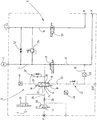
- the single figure shows a symbol representation of the circuit of a hydraulic system with an embodiment of the device according to the invention.
- a hydropneumatic pressure accumulator 2 via a storage line 4 with a working circuit 6 in connection, which is provided to supply pressure to a consumer via a connectable to the storage line 4 working line 8, which leads to a consumer port A.
- the second consumer port B is connected via a tank line 10 with a tank T.
- a charge and discharge circuit controlling the charge state of the memory 2 and the pressure of the storage line 4 is designated as a whole by 12.
- This has a power pressure compensator 14 in the form of a 3/3-way valve in the form of a proportional valve, the control piston 16 is centered by a spring assembly 18 in a locking center position from which the control piston 16 is deflected by means of control pressures, via a first control line 20 and a second control line 22 on the one piston side and the other piston side of the control piston 16 are effective.
- a pressure port 24 of the pressure compensator 14 is connectable via a supply line 26, which is secured by a check valve 28, and via a first control valve 30 to a pressure source P, which in the present case is a hydraulic pump.
- the first control valve 30 is a 3/2-way valve, which is electrically actuated.
- a tank port 32 of the pressure compensator 14 is via a second control valve 34 in the form of an electrically operated 2/2-way valve with tank T connectable.
- a storage port 36 is connected to the storage line 4 in connection.
- a control pressure is effective, which is related to the effective in the working line 8 of the working group 6 load pressure.
- a branch line 38 formed between working line 8 and control line 22 is provided for this purpose, in which a lockable connecting element 40 is located.
- the second control line 22 When released branch line 38, the second control line 22 performs the pressure of the working line 8, wherein the control piston 16 of the pressure compensator 14 in turn, in the same manner as in the first control line 20, a diaphragm 42 is connected upstream.
- a control pressure can be supplied to the second control line 22 from a control connection EXT, which control pressure is related to the load pressure in the working line 8, but is externally generated.
- the control pressures prevailing in the control lines 20 and 22 for deflections of the control piston 16 of the pressure compensator 14 are detected and signaled by a first pressure sensor 44 and a second pressure sensor 46.
- the working group 6 For the pressure supply of a particular consumer via the terminals A and B, the working group 6, a third control valve 48 and a fourth control valve 50 on. By actuating the third control valve 48, the storage line 4 can be connected to the working line 8. By actuating the fourth control valve 50, the consumer connection B can be connected to the tank line 10. Between the storage line 4 and tank line 10 are a check valve 52 and a pressure relief valve 54th
- the consumer to be supplied via the connections A, B may be a working cylinder of various types, as a preferred example of application, for example, a suspension cylinder of a hydropneumatic suspension.
- a suspension cylinder of a hydropneumatic suspension When released or activated suspension are by energizing electrically actuated third control valve 48 and electrically actuated fourth control valve 50, the two piston sides of the (not shown) suspension cylinder with the storage line 4 and with the tank line 10 in connection.
- third control valve 48 and fourth control valve 50 are in the locked state as shown in the drawing.
- a corresponding change in the control pressure in the second control line 22 results via the branch line 38.
- a pressure difference results compared to the first control line 20, which leads to the accumulator pressure for deflecting the pressure compensator 14 in one or the other sense of control, so that the storage connection 36 of the pressure compensator 14 comes into contact either with the pressure connection 24 or the tank connection 32 for a charging process or a discharge process.
- a pressure difference causing the deflection of the pressure compensator 14 in the control lines 20 and 22 is detected by the pressure sensor 44 and the pressure sensor 46, which provide a corresponding signal for the energization of the first control valve 30 or the second control valve 34 for a charging or discharging process.
Landscapes
- Engineering & Computer Science (AREA)
- Mechanical Engineering (AREA)
- Physics & Mathematics (AREA)
- Fluid Mechanics (AREA)
- General Engineering & Computer Science (AREA)
- Fluid-Pressure Circuits (AREA)
- Supply Devices, Intensifiers, Converters, And Telemotors (AREA)
- Vehicle Body Suspensions (AREA)
Abstract
2. Die Erfindung betrifft eine Einrichtung zum Steuern des Ladezustandes mindestens eines Druckspeichers (2), der Bestandteil eines Hydrauliksystems ist, das eine mit dem jeweiligen Speicher (2) verbindbare Arbeitsleitung (8) zur Druckversorgung eines Verbrauchers und einen Lade- und Ablasskreis (12) für wahlweises Verbinden des jeweiligen Speichers (2) mit einer Druckquelle (P) für einen Ladevorgang oder mit einem Tank (T) für einen Ablassvorgang aufweist, die dadurch gekennzeichnet ist, dass der Lade- und Ablasskreis (12) eine Druckwaage (14) aufweist, deren Steuerkolben (16) aus einer zentralen Sperrstellung in eine den betreffenden Speicher (2) mit der Druckquelle (P) verbindende Ladestellung oder in eine diesen mit dem Tank (T) verbindende Ablassstellung auslenkbar ist, und dass der Kolben (16) der Druckwaage (14) einerseits mit einem mit dem Druck des Speichers (2) in Bezug stehenden und andererseits mit einem mit dem Druck der Arbeitsleitung (8) in Bezug stehenden Steuerdruck beaufschlagbar ist.
Description
- Die Erfindung betrifft eine Einrichtung zum Steuern des Ladezustandes mindestens eines Druckspeichers, der Bestandteil eines Hydrauliksystems ist, das eine mit dem jeweiligen Speicher verbindbare Arbeitsleitung zur Druckversorgung eines Verbrauchers und einen Lade- und Ablasskreis für wahlweises Verbinden des jeweiligen Speichers mit einer Druckquelle für einen Ladevorgang oder mit einem Tank für einen Ablassvorgang aufweist.
- Bei Hydrauliksystemen, die zur Druckversorgung unterschiedlicher Verbraucher, wie Arbeitszylinder, hydraulischer Brems- oder Lenksysteme oder hydropneumatischer Federungssysteme, vorgesehen sind und bei denen mit der betreffenden Arbeitsleitung ein Druckspeicher verbindbar ist, ist es im Allgemeinen erforderlich, den Ladezustand, d.h. das Druckniveau des betreffenden Speichers, an den jeweiligen Betriebszustand des Systems anzupassen. U.a. gilt dies im besonderen Maße beispielsweise bei hydropneumatischen Federungssystemen, die bei mobilen Arbeitsgerätschaften wie Teleskopladern oder Baggern zum Einsatz kommen, wo es bei bestimmten Arbeitssituationen erforderlich ist, die Federung zu sperren. Im Hinblick auf die Betriebssicherheit ist es unumgänglich, den Ladezustand des Speichers an den jeweils herrschenden Lastdruck der Arbeitsleitung anzupassen, um sicherzustellen, dass bei einer nach dem Sperren erfolgenden Aktivierung der Federung keine Drucksprünge auftreten.
- Im Hinblick auf diese Problematik liegt der Erfindung die Aufgabe zugrunde, eine Einrichtung zur Verfügung zu stellen, die mit geringem Aufwand eine betriebssichere Steuerung des Ladezustandes eines betreffenden Druckspeichers in Anpassung an die betrieblichen Erfordernisse des zugehörigen Hydrauliksystems ermöglicht.
- Erfindungsgemäß ist diese Aufgabe durch eine Einrichtung gelöst, die die Merkmale des Patentanspruches 1 in seiner Gesamtheit aufweist.
- Nach dem kennzeichnenden Teil des Anspruches 1 besteht eine wesentliche Besonderheit der Erfindung darin, dass der Lade- und Ablasskreis eine Druckwaage aufweist, deren Steuerkolben aus einer zentralen Sperrstellung in eine den betreffenden Speicher mit der Druckquelle verbindenden Ladestellung oder in eine diesen mit dem Tank verbindende Ablassstellung auslenkbar ist, wobei der Kolben der Druckwaage einerseits mit einem mit dem Speicherdruck in Bezug stehenden und andererseits mit einem mit dem Druck der Arbeitsleitung in Bezug stehenden Steuerdruck beaufschlagbar ist.
- Mit geringem Steuerungsaufwand lässt sich dadurch das Druckniveau des Speichers dem Lastzustand in gewünschter Weise anpassen, wobei bei Benutzung einer Leistungsdruckwaage die Anpassung sicher und reaktionsschnell erfolgt.
- In vorteilhafter Weise kann eine Druckwaage in Form eines 3/3-Wege-Proportionalventils vorgesehen sein, das durch eine Federanordnung in die zentrale Sperrstellung vorgespannt ist.
- Hinsichtlich der Ansteuerung der Druckwaage kann die Anordnung mit Vorteil so getroffen sein, dass die eine Seite des Steuerkolbens der Druckwaage über eine erste Steuerleitung mit dem jeweiligen Druckspeicher in Verbindung ist und dass die andere Seite des Steuerkolbens über eine zweite Steuerleitung mit der Arbeitsleitung oder mit einem Anschluss für die Zufuhr eines extern generierten Steuerdruckes verbindbar ist. Dadurch besteht die Möglichkeit, den jeweiligen Lastdruck der Arbeitsleitung unmittelbar an einer Seite des Steuerkolbens der Druckwaage wirken zu lassen, an dessen anderer Seite der Speicherdruck anliegt, oder alternativ anstelle des Lastdruckes der Arbeitsleitung einen in Abhängigkeit vom Lastdruck der Arbeitsleitung extern generierten Steuerdruck an der Druckwaage wirken zu lassen. Mit Vorteil kann die Anordnung hierfür so getroffen sein, dass die Arbeitsleitung über eine sperrbare oder freigebbare Zweigleitung mit der zweiten Steuerleitung verbindbar ist.
- Bei besonders vorteilhaften Ausführungsbeispielen ist in erster und zweiter Steuerleitung jeweils eine dem Steuerkolben vorgeschaltete Blende angeordnet, beispielsweise in Form einer als dynamisches Dämpferglied wirksamen Messblende.
- Bei besonders vorteilhaften Ausführungsbeispielen weist der Lade- und Ablasskreis ein erstes Steuerventil, über das die Druckquelle mit dem Druckanschluss der Druckwaage verbindbar ist, und ein zweites Steuerventil auf, über das der Tankanschluss der Druckwaage mit dem Tank verbindbar ist, wobei vorzugsweise erstes und zweites Steuerventil elektrisch betätigbar sind.
- In besonders vorteilhafter Weise können ein erster Drucksensor, der den am Steuerkolben der Druckwaage herrschenden Druck der ersten Steuerleitung erkennt, sowie ein den am Steuerkolben herrschenden Druck der zweiten Steuerleitung erkennender zweiter Drucksensor vorgesehen sein. Mittels elektrischer Schaltsignale, die aufgrund der vom ersten und zweiten Drucksensor erkannten Druckwerten generiert sind, lassen sich erstes und zweites Steuerventil in der erforderlichen Entsprechung zum Zustand der Druckwaage bestromen, dass also bei der dem Ablasszustand entsprechenden Stellung der Druckwaage deren Tankanschluss zum Tank freigegeben ist oder dass bei der Ladestellung der Druckwaage deren Druckanschluss mit dem Speicher in Verbindung ist.
- Nachstehend ist die Erfindung anhand eines in der Zeichnung dargestellten Ausführungsbeispieles im Einzelnen erläutert. Die einzige Figur zeigt in Symboldarstellung die Schaltung eines Hydrauliksystems mit einem Ausführungsbeispiel der erfindungsgemäßen Einrichtung.
- Bei dem in der Zeichnung dargestellten Hydrauliksystem ist ein hydropneumatischer Druckspeicher 2 über eine Speicherleitung 4 mit einem Arbeitskreis 6 in Verbindung, der zur Druckversorgung eines Verbrauchers über eine mit der Speicherleitung 4 verbindbare Arbeitsleitung 8 vorgesehen ist, die zu einem Verbraucheranschluss A führt. Der zweite Verbraucheranschluss B ist über eine Tankleitung 10 mit einem Tank T verbindbar.
- Ein den Ladezustand des Speichers 2 und den Druck der Speicherleitung 4 steuernder Lade- und Ablasskreis ist als Ganzes mit 12 bezeichnet. Dieser weist eine Leistungs-Druckwaage 14 in Form eines 3/3-Wegeventils in Form eines Proportionalventils auf, dessen Steuerkolben 16 durch eine Federanordnung 18 in eine sperrende Mittelstellung zentriert ist, aus der der Steuerkolben 16 mittels Steuerdrücken auslenkbar ist, die über eine erste Steuerleitung 20 und eine zweite Steuerleitung 22 an der einen Kolbenseite bzw. der anderen Kolbenseite des Steuerkolbens 16 wirksam sind. Ein Druckanschluss 24 der Druckwaage 14 ist über eine Versorgungsleitung 26, die über ein Rückschlagventil 28 abgesichert ist, und über ein erstes Steuerventil 30 mit einer Druckquelle P verbindbar, bei der es sich vorliegend um eine Hydropumpe handelt. Das erste Steuerventil 30 ist ein 3/2-Wegeventil, das elektrisch betätigbar ist. Ein Tankanschluss 32 der Druckwaage 14 ist über ein zweites Steuerventil 34 in Form eines elektrisch betätigbaren 2/2-Wegeventiles mit Tank T verbindbar. Als weiterer Anschluss der Druckwaage 14 ist ein Speicheranschluss 36 mit der Speicherleitung 4 in Verbindung.
- An einem mit der Speicherleitung 4 verbundenen Speicheranschluss 36 ist der herrschende Ladedruck des Speichers 2 in der ersten Steuerleitung 20 und damit an der einen Seite des Steuerkolbens 16 der Druckwaage 14 wirksam, wobei dem Steuerkolben 16 eine Blende 37 vorgeschaltet ist. An der anderen Kolbenseite ist in der zugehörigen Steuerleitung 22 ein Steuerdruck wirksam, der mit dem in der Arbeitsleitung 8 des Arbeitskreises 6 wirksamen Lastdruck in Bezug steht. Bei dem vorliegenden Beispiel ist hierfür eine zwischen Arbeitsleitung 8 und Steuerleitung 22 gebildete Zweigleitung 38 vorgesehen, in der sich ein sperrbares Verbindungselement 40 befindet. Bei freigegebener Zweigleitung 38 führt die zweite Steuerleitung 22 den Druck der Arbeitsleitung 8, wobei dem Steuerkolben 16 der Druckwaage 14 in gleicher Weise wie bei der ersten Steuerleitung 20 wiederum eine Blende 42 vorgeschaltet ist. Bei geschlossener Zweigleitung 38 kann der zweiten Steuerleitung 22 von einem Steueranschluss EXT her ein Steuerdruck zugeführt werden, der mit dem Lastdruck in der Arbeitsleitung 8 in Bezug steht, jedoch extern generiert ist. Die in den Steuerleitungen 20 und 22 für Auslenkungen des Steuerkolbens 16 der Druckwaage 14 herrschenden Steuerdrücke werden von einem ersten Drucksensor 44 und einem zweiten Drucksensor 46 erkannt und signalisiert.
- Für die Druckversorgung eines betreffenden Verbrauchers über die Anschlüsse A und B weist der Arbeitskreis 6 ein drittes Steuerventil 48 und ein viertes Steuerventil 50 auf. Durch Betätigen des dritten Steuerventiles 48 ist die Speicherleitung 4 mit der Arbeitsleitung 8 verbindbar. Durch Betätigen des vierten Steuerventiles 50 ist der Verbraucheranschluss B mit der Tankleitung 10 verbindbar. Zwischen Speicherleitung 4 und Tankleitung 10 befinden sich ein Absperrventil 52 und ein Druckbegrenzungsventil 54.
- Bei dem über die Anschlüsse A, B zu versorgenden Verbraucher kann es sich um einen Arbeitszylinder verschiedenster Art handeln, als bevorzugtes Anwendungsbeispiel etwa um einen Federungszylinder einer hydropneumatischen Federung. Bei freigegebener oder aktivierter Federung sind durch Bestromen von elektrisch betätigbarem dritten Steuerventil 48 und elektrisch betätigbarem vierten Steuerventil 50 die beiden Kolbenseiten des (nicht gezeigten) Federungszylinders mit der Speicherleitung 4 bzw. mit der Tankleitung 10 in Verbindung.
- Wenn die hydropneumatische Federung verriegelt ist, sind drittes Steuerventil 48 und viertes Steuerventil 50 im Sperrzustand, wie er in der Zeichnung dargestellt ist. Bei Änderungen der am Federungszylinder wirkenden Lastkräfte und den entsprechenden Änderungen des Lastdruckes in der Arbeitsleitung 8 ergibt sich über die Zweigleitung 38 eine entsprechende Änderung des Steuerdruckes in der zweiten Steuerleitung 22. Eine gegenüber der ersten Steuerleitung 20, die den Speicherdruck führt, sich ergebende Druckdifferenz führt zur Auslenkung der Druckwaage 14 im einen oder anderen Steuersinn, so dass der Speicheranschluss 36 der Druckwaage 14 entweder mit dem Druckanschluss 24 oder dem Tankanschluss 32 für einen Ladevorgang bzw. einen Ablassvorgang in Verbindung kommt. Eine die Auslenkung der Druckwaage 14 bewirkende Druckdifferenz in den Steuerleitungen 20 und 22 wird durch den Drucksensor 44 bzw. den Drucksensor 46 erkannt, die ein entsprechendes Signal für die Bestromung des ersten Steuerventils 30 oder des zweiten Steuerventils 34 für einen Ladevorgang bzw. Ablassvorgang liefern. Somit ergibt sich eine Anpassung des Ladezustandes des Speichers 2 an den jeweiligen, in der Arbeitsleitung 8 herrschenden Lastdruck. Bei einer Freigabe oder Aktivierung der Federung nach vorangegangener Sperrung befindet sich daher der Speicher 2 in einem angepassten Ladezustand, so dass beim Entsperren der Federung kein Drucksprung auftritt.
Claims (9)
- Einrichtung zum Steuern des Ladezustandes mindestens eines Druckspeichers (2), der Bestandteil eines Hydrauliksystems ist, das eine mit dem jeweiligen Speicher (2) verbindbare Arbeitsleitung (8) zur Druckversorgung eines Verbrauchers und einen Lade- und Ablasskreis (12) für wahlweises Verbinden des jeweiligen Speichers (2) mit einer Druckquelle (P) für einen Ladevorgang oder mit einem Tank (T) für einen Ablassvorgang aufweist, dadurch gekennzeichnet, dass der Lade- und Ablasskreis (12) eine Druckwaage (14) aufweist, deren Steuerkolben (16) aus einer zentralen Sperrstellung in eine den betreffenden Speicher (2) mit der Druckquelle (P) verbindende Ladestellung oder in eine diesen mit dem Tank (T) verbindende Ablassstellung auslenkbar ist, und dass der Kolben (16) der Druckwaage (14) einerseits mit einem mit dem Druck des Speichers (2) in Bezug stehenden und andererseits mit einem mit dem Druck der Arbeitsleitung (8) in Bezug stehenden Steuerdruck beaufschlagbar ist.
- Einrichtung nach Anspruch 1, dadurch gekennzeichnet, dass eine Druckwaage (14) in Form eines 3/3-Wege-Proportionalventils vorgesehen ist, das durch eine Federanordnung (18) in die zentrale Sperrstellung vorgespannt ist.
- Einrichtung nach Anspruch 1 oder 2, dadurch gekennzeichnet, dass die eine Seite des Steuerkolbens (16) der Druckwaage (14) über eine erste Steuerleitung (20) mit dem jeweiligen Druckspeicher (2) in Verbindung ist und dass die andere Seite des Steuerkolbens (16) über eine zweite Steuerleitung (22) mit der Arbeitsleitung (8) oder mit einem Anschluss (EXT) für die Zufuhr eines extern generierten, mit dem Lastdruck der Arbeitsleitung (8) in Bezug stehenden Steuerdruckes verbindbar ist.
- Einrichtung nach einem der vorstehenden Ansprüche, dadurch gekennzeichnet, dass die Arbeitsleitung (8) über eine sperrbare oder freigebbare Zweigleitung (38, 40) mit der zweiten Steuerleitung (22) verbindbar ist.
- Einrichtung nach einem der vorstehenden Ansprüche, dadurch gekennzeichnet, dass in erster (20) und zweiter Steuerleitung (22) jeweils eine dem Steuerkolben (16) vorgeschaltete Blende (37) bzw. (42) angeordnet ist.
- Einrichtung nach einem der vorstehenden Ansprüche, dadurch gekennzeichnet, dass der Lade- und Ablasskreis (12) ein erstes Steuerventil (30), über das die Druckquelle (P) mit dem Druckanschluss (24) der Druckwaage (14) verbindbar ist, und ein zweites Steuerventil (34) aufweist, über das der Tankanschluss (32) der Druckwaage (14) mit dem Tank (T) verbindbar ist.
- Einrichtung nach einem der vorstehenden Ansprüche, dadurch gekennzeichnet, dass erstes (30) und zweites Steuerventil (34) elektrisch betätigbar sind.
- Einrichtung nach einem der vorstehenden Ansprüche, dadurch gekennzeichnet, dass ein erster Drucksensor (44), der den am Steuerkolben (16) der Druckwaage (14) herrschenden Druck der ersten Steuerleitung (20) erkennt, sowie ein zweiter Drucksensor (46) vorgesehen sind, der den am Steuerkolben (16) herrschenden Druck der zweiten Steuerleitung (22) erkennt.
- Einrichtung nach einem der vorstehenden Ansprüche, dadurch gekennzeichnet, dass erstes (30) und zweites Steuerventil (34) mittels Schaltsignalen betätigbar sind, die aufgrund der von erstem (44) und zweitem Drucksensor (46) erkannten Druckwerte generiert sind.
Applications Claiming Priority (2)
| Application Number | Priority Date | Filing Date | Title |
|---|---|---|---|
| DE102012016457.2A DE102012016457A1 (de) | 2012-08-17 | 2012-08-17 | Einrichtung zum Steuern des Ladezustandes mindestens eines Druckspeichers |
| EP13003721.1A EP2698545B1 (de) | 2012-08-17 | 2013-07-25 | Einrichtung zum Steuern des Ladezustandes mindestens eines Druckspeichers |
Related Parent Applications (3)
| Application Number | Title | Priority Date | Filing Date |
|---|---|---|---|
| EP13003721.1A Division EP2698545B1 (de) | 2012-08-17 | 2013-07-25 | Einrichtung zum Steuern des Ladezustandes mindestens eines Druckspeichers |
| EP13003721.1A Previously-Filed-Application EP2698545B1 (de) | 2012-08-17 | 2013-07-25 | Einrichtung zum Steuern des Ladezustandes mindestens eines Druckspeichers |
| EP13003721.1A Division-Into EP2698545B1 (de) | 2012-08-17 | 2013-07-25 | Einrichtung zum Steuern des Ladezustandes mindestens eines Druckspeichers |
Publications (2)
| Publication Number | Publication Date |
|---|---|
| EP3444482A1 true EP3444482A1 (de) | 2019-02-20 |
| EP3444482B1 EP3444482B1 (de) | 2021-09-08 |
Family
ID=48900730
Family Applications (2)
| Application Number | Title | Priority Date | Filing Date |
|---|---|---|---|
| EP13003721.1A Not-in-force EP2698545B1 (de) | 2012-08-17 | 2013-07-25 | Einrichtung zum Steuern des Ladezustandes mindestens eines Druckspeichers |
| EP18189531.9A Active EP3444482B1 (de) | 2012-08-17 | 2013-07-25 | Einrichtung zum steuern des ladezustandes mindestens eines druckspeichers |
Family Applications Before (1)
| Application Number | Title | Priority Date | Filing Date |
|---|---|---|---|
| EP13003721.1A Not-in-force EP2698545B1 (de) | 2012-08-17 | 2013-07-25 | Einrichtung zum Steuern des Ladezustandes mindestens eines Druckspeichers |
Country Status (2)
| Country | Link |
|---|---|
| EP (2) | EP2698545B1 (de) |
| DE (1) | DE102012016457A1 (de) |
Families Citing this family (7)
| Publication number | Priority date | Publication date | Assignee | Title |
|---|---|---|---|---|
| GB201500553D0 (en) | 2015-01-14 | 2015-02-25 | Bae Systems Plc | Hydraulic Actuators |
| DE102016119714A1 (de) | 2016-10-17 | 2018-04-19 | Deere & Company | Federungssystem für eine Fahrzeugachse |
| DE102017008359A1 (de) * | 2017-09-06 | 2019-03-07 | Hydac Fluidtechnik Gmbh | Ventil |
| CN109624636B (zh) * | 2018-12-12 | 2020-11-17 | 中联重科股份有限公司 | 油气悬架系统和车辆 |
| CN109625041B (zh) * | 2019-01-24 | 2022-04-05 | 北京万相融通科技股份有限公司 | 一种远程采集货运列车空重状态的方法 |
| DE102021004608A1 (de) * | 2021-09-11 | 2023-03-16 | Hydac Mobilhydraulik Gmbh | Betätigungsvorrichtung für zumindest einen fluidisch antreibbaren Verbraucher |
| CN114263822B (zh) * | 2021-12-23 | 2023-04-25 | 中国电子科技集团公司第三十八研究所 | 一种雷达举升机构的防解锁冲击液压系统及方法 |
Citations (4)
| Publication number | Priority date | Publication date | Assignee | Title |
|---|---|---|---|---|
| DE19652684A1 (de) * | 1996-12-18 | 1998-06-25 | Linde Ag | Flurförderzeug mit einer Hubvorrichtung |
| DE19743005A1 (de) * | 1996-10-01 | 1998-06-25 | Caterpillar Inc | Laufsteuersystem |
| WO2008088044A1 (ja) * | 2007-01-18 | 2008-07-24 | Hitachi Construction Machinery Co., Ltd. | 油圧作業機の振動抑制装置および油圧作業機 |
| EP2375086A2 (de) * | 2010-04-07 | 2011-10-12 | Hydac Filtertechnik Gmbh | Hydraulische Anlage |
-
2012
- 2012-08-17 DE DE102012016457.2A patent/DE102012016457A1/de not_active Withdrawn
-
2013
- 2013-07-25 EP EP13003721.1A patent/EP2698545B1/de not_active Not-in-force
- 2013-07-25 EP EP18189531.9A patent/EP3444482B1/de active Active
Patent Citations (4)
| Publication number | Priority date | Publication date | Assignee | Title |
|---|---|---|---|---|
| DE19743005A1 (de) * | 1996-10-01 | 1998-06-25 | Caterpillar Inc | Laufsteuersystem |
| DE19652684A1 (de) * | 1996-12-18 | 1998-06-25 | Linde Ag | Flurförderzeug mit einer Hubvorrichtung |
| WO2008088044A1 (ja) * | 2007-01-18 | 2008-07-24 | Hitachi Construction Machinery Co., Ltd. | 油圧作業機の振動抑制装置および油圧作業機 |
| EP2375086A2 (de) * | 2010-04-07 | 2011-10-12 | Hydac Filtertechnik Gmbh | Hydraulische Anlage |
Also Published As
| Publication number | Publication date |
|---|---|
| EP3444482B1 (de) | 2021-09-08 |
| DE102012016457A1 (de) | 2014-02-20 |
| EP2698545A2 (de) | 2014-02-19 |
| EP2698545B1 (de) | 2022-03-16 |
| EP2698545A3 (de) | 2018-03-21 |
Similar Documents
| Publication | Publication Date | Title |
|---|---|---|
| EP3444482B1 (de) | Einrichtung zum steuern des ladezustandes mindestens eines druckspeichers | |
| DE102018206462A1 (de) | Hydraulische Achshöhenverstellung für eine mobile Arbeitsmaschine | |
| DE4108915C2 (de) | Hydraulische Einrichtung zur Druckmittelversorgung eines bevorrechtigten Primärlastkreises | |
| EP1963118B1 (de) | Hydropneumatische achsfederung für fahrzeuge | |
| DE102013102069A1 (de) | Proportional-Wegeventil sowie hydraulische Schaltung und hydropneumatisches Federungssystem mit einem derartigen Ventil | |
| EP1989450A1 (de) | Hydraulische steueranordnung | |
| EP2675672B1 (de) | Mehrkreisschutzventil für eine druckluftversorgungseinrichtung eines fahrzeugs und verfahren zum betreiben eines mehrkreisschutzventils | |
| EP4065360A1 (de) | Elektrohydrostatisches system mit drucksensor | |
| EP2672125B1 (de) | Hydrauliksystem zur sicheren Druckversorgung mindestens eines Verbrauchers | |
| WO2023036701A1 (de) | Betätigungsvorrichtung für zumindest einen fluidisch antreibbaren verbraucher | |
| EP3625457B1 (de) | Steuervorrichtung zum versorgen mindestens eines hydraulischen verbrauchers mit fluid | |
| DE102010054108A1 (de) | Ventilanordnung zur Steuerung eines Zusatz-Lenksystems bei mehrachsigen Fahrzeugen, insbesondere Mobilkranen | |
| DE102015226432A1 (de) | Bremsventilanordnung und Verfahren für eine Bremsventilanordnung | |
| EP3398418A1 (de) | Hydrauliksystem einer land- oder bauwirtschaftlich nutzbaren arbeitsmaschine | |
| DE10107644B4 (de) | Hydropneumatische Federung für Fahrzeuge mit stark wechselnden Achslasten | |
| DE4308004C2 (de) | Hydraulische Steuereinrichtung für mehrere Verbraucher | |
| DE3013853A1 (de) | Hydraulikanlage, insbesondere fuer kraftfahrzeuge | |
| EP2466154B1 (de) | Elektrohydraulische Steuervorrichtung | |
| EP3135924B1 (de) | Hydrauliksteuerung | |
| EP2620656B1 (de) | Load-Sensing-Ventilbaugruppe mit Drucksteuerung | |
| EP4455488A1 (de) | Vorrichtung zum betreiben einer lastgesteuerten hydraulikver-sorgung eines landwirtschaftlichen traktors | |
| EP2896839B1 (de) | Vorrichtung zum Sperren und zum Druckanpassen | |
| EP4341565A1 (de) | Betätigungsvorrichtung für zumindest einen fluidisch antreibbaren verbraucher | |
| EP1954949B1 (de) | Hydraulische steuervorrichtung | |
| DE102007045802A1 (de) | Hydraulische Steueranordnung |
Legal Events
| Date | Code | Title | Description |
|---|---|---|---|
| PUAI | Public reference made under article 153(3) epc to a published international application that has entered the european phase |
Free format text: ORIGINAL CODE: 0009012 |
|
| STAA | Information on the status of an ep patent application or granted ep patent |
Free format text: STATUS: THE APPLICATION HAS BEEN PUBLISHED |
|
| AC | Divisional application: reference to earlier application |
Ref document number: 2698545 Country of ref document: EP Kind code of ref document: P |
|
| AK | Designated contracting states |
Kind code of ref document: A1 Designated state(s): AL AT BE BG CH CY CZ DE DK EE ES FI FR GB GR HR HU IE IS IT LI LT LU LV MC MK MT NL NO PL PT RO RS SE SI SK SM TR |
|
| AX | Request for extension of the european patent |
Extension state: BA ME |
|
| STAA | Information on the status of an ep patent application or granted ep patent |
Free format text: STATUS: REQUEST FOR EXAMINATION WAS MADE |
|
| 17P | Request for examination filed |
Effective date: 20190820 |
|
| RAX | Requested extension states of the european patent have changed |
Extension state: BA Payment date: 20190820 Extension state: ME Payment date: 20190820 |
|
| GRAP | Despatch of communication of intention to grant a patent |
Free format text: ORIGINAL CODE: EPIDOSNIGR1 |
|
| STAA | Information on the status of an ep patent application or granted ep patent |
Free format text: STATUS: GRANT OF PATENT IS INTENDED |
|
| INTG | Intention to grant announced |
Effective date: 20210628 |
|
| GRAS | Grant fee paid |
Free format text: ORIGINAL CODE: EPIDOSNIGR3 |
|
| GRAA | (expected) grant |
Free format text: ORIGINAL CODE: 0009210 |
|
| STAA | Information on the status of an ep patent application or granted ep patent |
Free format text: STATUS: THE PATENT HAS BEEN GRANTED |
|
| AC | Divisional application: reference to earlier application |
Ref document number: 2698545 Country of ref document: EP Kind code of ref document: P |
|
| AK | Designated contracting states |
Kind code of ref document: B1 Designated state(s): AL AT BE BG CH CY CZ DE DK EE ES FI FR GB GR HR HU IE IS IT LI LT LU LV MC MK MT NL NO PL PT RO RS SE SI SK SM TR |
|
| REG | Reference to a national code |
Ref country code: GB Ref legal event code: FG4D Free format text: NOT ENGLISH |
|
| REG | Reference to a national code |
Ref country code: AT Ref legal event code: REF Ref document number: 1428837 Country of ref document: AT Kind code of ref document: T Effective date: 20210915 Ref country code: CH Ref legal event code: EP |
|
| REG | Reference to a national code |
Ref country code: IE Ref legal event code: FG4D Free format text: LANGUAGE OF EP DOCUMENT: GERMAN |
|
| REG | Reference to a national code |
Ref country code: DE Ref legal event code: R096 Ref document number: 502013015926 Country of ref document: DE |
|
| REG | Reference to a national code |
Ref country code: SE Ref legal event code: TRGR |
|
| REG | Reference to a national code |
Ref country code: LT Ref legal event code: MG9D |
|
| REG | Reference to a national code |
Ref country code: NL Ref legal event code: MP Effective date: 20210908 |
|
| PG25 | Lapsed in a contracting state [announced via postgrant information from national office to epo] |
Ref country code: LT Free format text: LAPSE BECAUSE OF FAILURE TO SUBMIT A TRANSLATION OF THE DESCRIPTION OR TO PAY THE FEE WITHIN THE PRESCRIBED TIME-LIMIT Effective date: 20210908 Ref country code: BG Free format text: LAPSE BECAUSE OF FAILURE TO SUBMIT A TRANSLATION OF THE DESCRIPTION OR TO PAY THE FEE WITHIN THE PRESCRIBED TIME-LIMIT Effective date: 20211208 Ref country code: NO Free format text: LAPSE BECAUSE OF FAILURE TO SUBMIT A TRANSLATION OF THE DESCRIPTION OR TO PAY THE FEE WITHIN THE PRESCRIBED TIME-LIMIT Effective date: 20211208 Ref country code: HR Free format text: LAPSE BECAUSE OF FAILURE TO SUBMIT A TRANSLATION OF THE DESCRIPTION OR TO PAY THE FEE WITHIN THE PRESCRIBED TIME-LIMIT Effective date: 20210908 Ref country code: ES Free format text: LAPSE BECAUSE OF FAILURE TO SUBMIT A TRANSLATION OF THE DESCRIPTION OR TO PAY THE FEE WITHIN THE PRESCRIBED TIME-LIMIT Effective date: 20210908 Ref country code: FI Free format text: LAPSE BECAUSE OF FAILURE TO SUBMIT A TRANSLATION OF THE DESCRIPTION OR TO PAY THE FEE WITHIN THE PRESCRIBED TIME-LIMIT Effective date: 20210908 Ref country code: RS Free format text: LAPSE BECAUSE OF FAILURE TO SUBMIT A TRANSLATION OF THE DESCRIPTION OR TO PAY THE FEE WITHIN THE PRESCRIBED TIME-LIMIT Effective date: 20210908 |
|
| PG25 | Lapsed in a contracting state [announced via postgrant information from national office to epo] |
Ref country code: LV Free format text: LAPSE BECAUSE OF FAILURE TO SUBMIT A TRANSLATION OF THE DESCRIPTION OR TO PAY THE FEE WITHIN THE PRESCRIBED TIME-LIMIT Effective date: 20210908 Ref country code: GR Free format text: LAPSE BECAUSE OF FAILURE TO SUBMIT A TRANSLATION OF THE DESCRIPTION OR TO PAY THE FEE WITHIN THE PRESCRIBED TIME-LIMIT Effective date: 20211209 |
|
| PG25 | Lapsed in a contracting state [announced via postgrant information from national office to epo] |
Ref country code: IS Free format text: LAPSE BECAUSE OF FAILURE TO SUBMIT A TRANSLATION OF THE DESCRIPTION OR TO PAY THE FEE WITHIN THE PRESCRIBED TIME-LIMIT Effective date: 20220108 Ref country code: SM Free format text: LAPSE BECAUSE OF FAILURE TO SUBMIT A TRANSLATION OF THE DESCRIPTION OR TO PAY THE FEE WITHIN THE PRESCRIBED TIME-LIMIT Effective date: 20210908 Ref country code: SK Free format text: LAPSE BECAUSE OF FAILURE TO SUBMIT A TRANSLATION OF THE DESCRIPTION OR TO PAY THE FEE WITHIN THE PRESCRIBED TIME-LIMIT Effective date: 20210908 Ref country code: RO Free format text: LAPSE BECAUSE OF FAILURE TO SUBMIT A TRANSLATION OF THE DESCRIPTION OR TO PAY THE FEE WITHIN THE PRESCRIBED TIME-LIMIT Effective date: 20210908 Ref country code: PT Free format text: LAPSE BECAUSE OF FAILURE TO SUBMIT A TRANSLATION OF THE DESCRIPTION OR TO PAY THE FEE WITHIN THE PRESCRIBED TIME-LIMIT Effective date: 20220110 Ref country code: PL Free format text: LAPSE BECAUSE OF FAILURE TO SUBMIT A TRANSLATION OF THE DESCRIPTION OR TO PAY THE FEE WITHIN THE PRESCRIBED TIME-LIMIT Effective date: 20210908 Ref country code: NL Free format text: LAPSE BECAUSE OF FAILURE TO SUBMIT A TRANSLATION OF THE DESCRIPTION OR TO PAY THE FEE WITHIN THE PRESCRIBED TIME-LIMIT Effective date: 20210908 Ref country code: EE Free format text: LAPSE BECAUSE OF FAILURE TO SUBMIT A TRANSLATION OF THE DESCRIPTION OR TO PAY THE FEE WITHIN THE PRESCRIBED TIME-LIMIT Effective date: 20210908 Ref country code: CZ Free format text: LAPSE BECAUSE OF FAILURE TO SUBMIT A TRANSLATION OF THE DESCRIPTION OR TO PAY THE FEE WITHIN THE PRESCRIBED TIME-LIMIT Effective date: 20210908 Ref country code: AL Free format text: LAPSE BECAUSE OF FAILURE TO SUBMIT A TRANSLATION OF THE DESCRIPTION OR TO PAY THE FEE WITHIN THE PRESCRIBED TIME-LIMIT Effective date: 20210908 |
|
| REG | Reference to a national code |
Ref country code: DE Ref legal event code: R097 Ref document number: 502013015926 Country of ref document: DE |
|
| PLBE | No opposition filed within time limit |
Free format text: ORIGINAL CODE: 0009261 |
|
| STAA | Information on the status of an ep patent application or granted ep patent |
Free format text: STATUS: NO OPPOSITION FILED WITHIN TIME LIMIT |
|
| PG25 | Lapsed in a contracting state [announced via postgrant information from national office to epo] |
Ref country code: DK Free format text: LAPSE BECAUSE OF FAILURE TO SUBMIT A TRANSLATION OF THE DESCRIPTION OR TO PAY THE FEE WITHIN THE PRESCRIBED TIME-LIMIT Effective date: 20210908 |
|
| 26N | No opposition filed |
Effective date: 20220609 |
|
| PG25 | Lapsed in a contracting state [announced via postgrant information from national office to epo] |
Ref country code: SI Free format text: LAPSE BECAUSE OF FAILURE TO SUBMIT A TRANSLATION OF THE DESCRIPTION OR TO PAY THE FEE WITHIN THE PRESCRIBED TIME-LIMIT Effective date: 20210908 |
|
| PG25 | Lapsed in a contracting state [announced via postgrant information from national office to epo] |
Ref country code: IT Free format text: LAPSE BECAUSE OF FAILURE TO SUBMIT A TRANSLATION OF THE DESCRIPTION OR TO PAY THE FEE WITHIN THE PRESCRIBED TIME-LIMIT Effective date: 20210908 |
|
| REG | Reference to a national code |
Ref country code: DE Ref legal event code: R119 Ref document number: 502013015926 Country of ref document: DE |
|
| PG25 | Lapsed in a contracting state [announced via postgrant information from national office to epo] |
Ref country code: MC Free format text: LAPSE BECAUSE OF FAILURE TO SUBMIT A TRANSLATION OF THE DESCRIPTION OR TO PAY THE FEE WITHIN THE PRESCRIBED TIME-LIMIT Effective date: 20210908 |
|
| REG | Reference to a national code |
Ref country code: CH Ref legal event code: PL Ref country code: SE Ref legal event code: EUG |
|
| GBPC | Gb: european patent ceased through non-payment of renewal fee |
Effective date: 20220725 |
|
| REG | Reference to a national code |
Ref country code: BE Ref legal event code: MM Effective date: 20220731 |
|
| PG25 | Lapsed in a contracting state [announced via postgrant information from national office to epo] |
Ref country code: LU Free format text: LAPSE BECAUSE OF NON-PAYMENT OF DUE FEES Effective date: 20220725 Ref country code: LI Free format text: LAPSE BECAUSE OF NON-PAYMENT OF DUE FEES Effective date: 20220731 Ref country code: FR Free format text: LAPSE BECAUSE OF NON-PAYMENT OF DUE FEES Effective date: 20220731 Ref country code: CH Free format text: LAPSE BECAUSE OF NON-PAYMENT OF DUE FEES Effective date: 20220731 Ref country code: SE Free format text: LAPSE BECAUSE OF NON-PAYMENT OF DUE FEES Effective date: 20220726 |
|
| PG25 | Lapsed in a contracting state [announced via postgrant information from national office to epo] |
Ref country code: GB Free format text: LAPSE BECAUSE OF NON-PAYMENT OF DUE FEES Effective date: 20220725 Ref country code: DE Free format text: LAPSE BECAUSE OF NON-PAYMENT OF DUE FEES Effective date: 20230201 Ref country code: BE Free format text: LAPSE BECAUSE OF NON-PAYMENT OF DUE FEES Effective date: 20220731 |
|
| PG25 | Lapsed in a contracting state [announced via postgrant information from national office to epo] |
Ref country code: IE Free format text: LAPSE BECAUSE OF NON-PAYMENT OF DUE FEES Effective date: 20220725 |
|
| REG | Reference to a national code |
Ref country code: AT Ref legal event code: MM01 Ref document number: 1428837 Country of ref document: AT Kind code of ref document: T Effective date: 20220725 |
|
| PG25 | Lapsed in a contracting state [announced via postgrant information from national office to epo] |
Ref country code: AT Free format text: LAPSE BECAUSE OF NON-PAYMENT OF DUE FEES Effective date: 20220725 |
|
| PG25 | Lapsed in a contracting state [announced via postgrant information from national office to epo] |
Ref country code: HU Free format text: LAPSE BECAUSE OF FAILURE TO SUBMIT A TRANSLATION OF THE DESCRIPTION OR TO PAY THE FEE WITHIN THE PRESCRIBED TIME-LIMIT; INVALID AB INITIO Effective date: 20130725 |
|
| PG25 | Lapsed in a contracting state [announced via postgrant information from national office to epo] |
Ref country code: MK Free format text: LAPSE BECAUSE OF FAILURE TO SUBMIT A TRANSLATION OF THE DESCRIPTION OR TO PAY THE FEE WITHIN THE PRESCRIBED TIME-LIMIT Effective date: 20210908 Ref country code: CY Free format text: LAPSE BECAUSE OF FAILURE TO SUBMIT A TRANSLATION OF THE DESCRIPTION OR TO PAY THE FEE WITHIN THE PRESCRIBED TIME-LIMIT Effective date: 20210908 |
|
| PG25 | Lapsed in a contracting state [announced via postgrant information from national office to epo] |
Ref country code: TR Free format text: LAPSE BECAUSE OF FAILURE TO SUBMIT A TRANSLATION OF THE DESCRIPTION OR TO PAY THE FEE WITHIN THE PRESCRIBED TIME-LIMIT Effective date: 20210908 |
|
| PG25 | Lapsed in a contracting state [announced via postgrant information from national office to epo] |
Ref country code: MT Free format text: LAPSE BECAUSE OF FAILURE TO SUBMIT A TRANSLATION OF THE DESCRIPTION OR TO PAY THE FEE WITHIN THE PRESCRIBED TIME-LIMIT Effective date: 20210908 |