EP3444509B1 - Thermostatic faucet having plastic body - Google Patents
Thermostatic faucet having plastic body Download PDFInfo
- Publication number
- EP3444509B1 EP3444509B1 EP18158358.4A EP18158358A EP3444509B1 EP 3444509 B1 EP3444509 B1 EP 3444509B1 EP 18158358 A EP18158358 A EP 18158358A EP 3444509 B1 EP3444509 B1 EP 3444509B1
- Authority
- EP
- European Patent Office
- Prior art keywords
- chamber
- plastic
- water inlet
- inner body
- mating
- Prior art date
- Legal status (The legal status is an assumption and is not a legal conclusion. Google has not performed a legal analysis and makes no representation as to the accuracy of the status listed.)
- Active
Links
Images


Classifications
-
- F—MECHANICAL ENGINEERING; LIGHTING; HEATING; WEAPONS; BLASTING
- F16—ENGINEERING ELEMENTS AND UNITS; GENERAL MEASURES FOR PRODUCING AND MAINTAINING EFFECTIVE FUNCTIONING OF MACHINES OR INSTALLATIONS; THERMAL INSULATION IN GENERAL
- F16K—VALVES; TAPS; COCKS; ACTUATING-FLOATS; DEVICES FOR VENTING OR AERATING
- F16K19/00—Arrangements of valves and flow lines specially adapted for mixing fluids
- F16K19/006—Specially adapted for faucets
-
- E—FIXED CONSTRUCTIONS
- E03—WATER SUPPLY; SEWERAGE
- E03C—DOMESTIC PLUMBING INSTALLATIONS FOR FRESH WATER OR WASTE WATER; SINKS
- E03C1/00—Domestic plumbing installations for fresh water or waste water; Sinks
- E03C1/02—Plumbing installations for fresh water
- E03C1/04—Water-basin installations specially adapted to wash-basins or baths
- E03C1/041—Water-basin installations specially adapted to wash-basins or baths having provisions against scalding, e.g. temperature limiting devices, external covers
-
- F—MECHANICAL ENGINEERING; LIGHTING; HEATING; WEAPONS; BLASTING
- F16—ENGINEERING ELEMENTS AND UNITS; GENERAL MEASURES FOR PRODUCING AND MAINTAINING EFFECTIVE FUNCTIONING OF MACHINES OR INSTALLATIONS; THERMAL INSULATION IN GENERAL
- F16K—VALVES; TAPS; COCKS; ACTUATING-FLOATS; DEVICES FOR VENTING OR AERATING
- F16K11/00—Multiple-way valves, e.g. mixing valves; Pipe fittings incorporating such valves
- F16K11/10—Multiple-way valves, e.g. mixing valves; Pipe fittings incorporating such valves with two or more closure members not moving as a unit
- F16K11/20—Multiple-way valves, e.g. mixing valves; Pipe fittings incorporating such valves with two or more closure members not moving as a unit operated by separate actuating members
- F16K11/207—Multiple-way valves, e.g. mixing valves; Pipe fittings incorporating such valves with two or more closure members not moving as a unit operated by separate actuating members with two handles or actuating mechanisms at opposite sides of the housing
-
- F—MECHANICAL ENGINEERING; LIGHTING; HEATING; WEAPONS; BLASTING
- F16—ENGINEERING ELEMENTS AND UNITS; GENERAL MEASURES FOR PRODUCING AND MAINTAINING EFFECTIVE FUNCTIONING OF MACHINES OR INSTALLATIONS; THERMAL INSULATION IN GENERAL
- F16K—VALVES; TAPS; COCKS; ACTUATING-FLOATS; DEVICES FOR VENTING OR AERATING
- F16K27/00—Construction of housing; Use of materials therefor
Definitions
- the present invention relates to a thermostatic faucet structure, and more particularly to a thermostatic faucet having a plastic body.
- thermostatic faucets on the market are mainly made of copper, which is expensive and leads to higher manufacturing costs. Moreover, the thermal conductivity of a copper material is good. When in use, hot water easily makes the surface temperature of the faucet body too high. The faucet body may scald the user.
- Cipheral Patent Publication No. CN203115189U discloses a thermostatic faucet structure which is directly connected to a temperature control mechanism through a copper pipe.
- the copper pipe is an independent hot water inlet passage and is not in contact with an outer housing, so that the faucet won't scald the user.
- the faucet adopts the outer housing which is not in contact with water and an all-plastic inner core structure. This can reduce the amount of copper greatly and reduce the material cost significantly.
- the copper pipe needs to be connected to a hot water supply pipe and the temperature control mechanism through a water inlet connector and a water outlet connector respectively, and then a hot water passage can be formed. That is, the hot water passage of thermostatic faucet structure is formed by multiple components, which has high risk of water leakage and high manufacturing cost.
- thermostatic valve core of the temperature control mechanism of the thermostatic faucet structure and the flow valve core of the flow control mechanism are connected with the plastic inner core, both adopt lids to connect with the plastic inner core by means of screw threads.
- the stress part of the faucet body is centralized on the plastic inner core, reducing the strength performance of the faucet body.
- the strength of the plastic screw threads on the plastic inner core is not enough.
- the faucet body is easy to aging, which easily leads to water leakage.
- EP 2 241 685 A2 , EP 2 388 676 A2 and EP 2 386 927 A2 disclose known thermostatic faucets.
- CN 203 115 189 U discloses a thermostatic faucet as defined in the preamble of claim 1.
- the primary object of the present invention is to provide a thermostatic faucet having a plastic body.
- the thermostatic faucet comprises a plastic inner body which is in contact with water and a metal housing which is not in contact with water to prevent the user from being scalded.
- a cold water passage and a hot water passage are integrally formed in the plastic inner body to reduce the parts, simplify the assembly and lower the manufacturing cost.
- the thermostatic faucet of the present invention comprises, as defined in claim 1, a metal housing, a plastic inner body disposed in the metal housing, a plastic valve rod and a plastic shaft seat which are connected in the plastic inner body, a flow valve core and a thermostatic valve core which pass through the metal housing and are mated with the plastic valve rod and the plastic shaft seat respectively.
- the plastic inner body is provided with a first water inlet connector, a second water inlet connector and a water outlet connector.
- the first water inlet connector, the second water inlet connector and the water outlet connector are integrally formed with the plastic inner body.
- the first water inlet connector is connected with the plastic shaft seat through a chamber of the plastic inner body to form a first water inlet passage.
- the second water inlet connector is connected with the plastic shaft seat to form a second water inlet passage.
- the first water inlet passage is a hot water passage or a cold water passage, correspondingly, the second water inlet passage is a cold water passage or a hot water passage.
- the plastic valve rod cooperates with the plastic inner body to form a chamber communicated with the water outlet connector to form a water outlet passage.
- the plastic inner body has a first chamber, a second chamber, a third chamber and a mating chamber therein.
- the second chamber, the third chamber and the mating chamber communicate with each other.
- the mating chamber is connected between the second chamber and the third chamber.
- the plastic valve rod is accommodated in the second chamber.
- One end of the plastic valve rod is connected to one end of the mating chamber.
- the plastic shaft seat is fitted in the third chamber and has one end connected to another end of the mating chamber.
- One end of the first chamber communicates with the plastic shaft seat in the third chamber. Another end of the first chamber is provided with a plug.
- the first water inlet connector is connected with the plastic shaft seat through the first chamber to form the first water inlet passage.
- An inner chamber of the plastic shaft seat, the mating chamber and an inner chamber of the plastic valve rod form a mixed water passage.
- the plastic valve rod cooperates with the second chamber to form a water outlet chamber.
- the water outlet chamber communicates with the water outlet connector to form the water outlet passage.
- the metal housing includes a front housing and a rear end cover to mate and connect with each other. Two ends of the front housing are formed with mating holes for insertion of the flow valve core and the thermostatic valve core, respectively.
- the flow valve core passes through the mating hole at one end of the front housing and is partially accommodated in the second chamber of the plastic inner body and connected with the plastic valve rod and then is fixed by a metal sealing lid.
- the metal sealing lid is provided with a screw portion.
- the screw portion is inwardly reduced to form a reduced portion.
- the metal sealing lid is sleeved on the flow valve core.
- the reduced portion is connected in the second chamber of the plastic inner body.
- the screw portion is screwed with the mating hole.
- a stepped surface formed between the screw portion and the reduced portion is pressed against the plug of the plastic inner body.
- a thermal insulation pad is provided between the plug and the metal sealing lid.
- the thermostatic valve core passes through the mating hole at the other end of the front housing and is partially accommodated in the plastic shaft seat and then fixed by a metal upper lid to be screwed with the mating hole.
- the metal housing is made of zinc alloy.
- the plug is a copper plug.
- the present invention adopts the metal housing to ensure the quality of the product.
- the metal housing is not in contact with water.
- the plastic inner body is in contact with water.
- the plastic inner body plays the role of thermal insulation, so that the thermostatic faucet won't scald the user.
- the thermostatic faucet the cold water passage, the hot water passage, the mixed water passage and the water outlet passage are integrally formed in the plastic inner body.
- the plastic inner body has the water inlet connectors and the water outlet connector.
- the water inlet connectors and the water outlet connector are directly connected with the external water passages. The parts are reduced, the production process is simplified, the manufacturing cost of the thermostatic faucet is lowered, and the risk of water leakage generated by the multiple components is reduced.
- the fixing positions of the flow valve core and the thermostatic valve core relative to the plastic inner body are transferred from the plastic inner body to the metal housing, so that the stress points of the thermostatic faucet won't be concentrated on the plastic inner body to affect the strength performance of the product.
- the metal sealing lid, the metal upper lid and the metal housing are connected through metal threads. Compared with plastic threads, the strength of the metal threads is larger, thereby lowering the risk of leakage.
- the present invention discloses a thermostatic faucet having a plastic body.
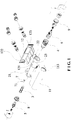
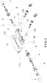
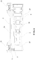
- the thermostatic faucet comprises a metal housing 1, a plastic inner body 2 disposed in the metal housing 1, a plastic valve rod 3 and a plastic shaft seat 4 which are connected in the plastic inner body 2, a flow valve core 5 and a thermostatic valve core 6 which pass through the metal housing 1 and are mated with the plastic valve rod 2 and the plastic shaft seat 4, respectively.
- the plastic inner body 2 is provided with a first water inlet connector 21, a second water inlet connector 22 and a water outlet connector 23.
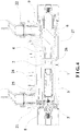
- the plastic inner body 2 has a first chamber 24, a second chamber 25, a third chamber 27, and a mating chamber 26 therein.
- the second chamber 25, the third chamber 27 and the mating chamber 26 communicate with each other.
- the mating chamber 26 is connected between the second chamber 25 and the third chamber 27.
- the plastic valve rod 3 is accommodated in the second chamber 25.
- One end of the plastic valve rod 3 is connected to one end of the mating chamber 26.
- the plastic shaft seat 4 is fitted in the third chamber 27 and has one end connected to another end of the mating chamber 26.
- the first water inlet connector 21 is connected to the sidewall of the first chamber 24 and communicates with the first chamber 24.
- the first water inlet connector 21 is connected with the plastic shaft seat 4 through the first chamber 24 to form a first water inlet passage.
- the second water inlet connector 22 is connected with the plastic shaft seat 4 to form a second water inlet passage.
- the first water inlet passage is a hot water passage or a cold water passage, correspondingly, and the second water inlet passage is a cold water passage or a hot water passage.
- An inner chamber of the plastic shaft seat 4, the mating chamber 26 and an inner chamber of the plastic valve rod 3 form a mixed water passage.
- the plastic valve rod 3 cooperates with the second chamber 25 to form a water outlet chamber.
- the water outlet chamber communicates with the water outlet connector 23 to form a water outlet passage.
- the plastic inner body 2, the plug 7, the plastic valve rod 3 and the plastic shaft seat 4 jointly form a main body assembly.
- the present invention adopts the metal housing 1 to ensure the quality of the product.
- the metal housing 1 is not in contact with water.
- the plastic inner body 2 is in contact with water.
- the plastic inner body 2 plays the role of thermal insulation, so that the thermostatic faucet won't scald the user.
- the thermostatic faucet the cold water passage, the hot water passage, the mixed water passage and the water outlet passage are integrally formed in the plastic inner body 2.
- the plastic inner body 2 has the first water inlet connector 21, the second water inlet connector 22 and the water outlet connector 23.
- the first water inlet connector 21, the second water inlet connector 22 and the water outlet connector 23 are directly connected with the external water passages. The parts are reduced, the production process is simplified, the manufacturing cost of the thermostatic faucet is lowered, and the risk of water leakage generated by the multiple components is reduced.
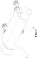
- the metal housing 1 may be made of zinc alloy, and includes a front housing 11 and a rear end cover 12.
- the middle portion of the front housing 11 is formed with a notch 111.
- Two ends of the front housing 11 are formed with a first mating hole 112 and a second mating hole 113 for insertion of the flow valve core 5 and the thermostatic valve core 6, respectively.
- the inner sides of the first mating hole 112 and the second mating hole 113 are formed with screw threads.
- the rear end cover 12 has a notch 121.
- the notch 121 cooperates with the notch 111 of the front housing 11 to form a third mating hole through which the water outlet connector 23 passes.
- the front end cover 12 further has a fourth mating hole 122 and a fifth mating hole 123 to mate with the first water inlet connector 21 and the second water inlet connector 22 respectively.
- the flow valve core 5 passes through the first mating hole 112 and is partially accommodated in the second chamber 25 of the plastic inner body 2 and is connected with the plastic valve rod 3 and then is fixed by a metal sealing lid 8.
- the metal sealing lid 8 is provided with a screw portion 81 mated with the first mating hole 112 of the front housing 11.
- the screw portion 81 is inwardly reduced to form a reduced portion 82.
- the metal sealing lid 8 is sleeved on the flow valve core 5.
- the reduced portion 82 is connected in the second chamber 25 of the plastic inner body 2.
- the screw portion 81 is screwed with the first mating hole 112 of the front housing 11.
- a stepped surface 83 formed between the screw portion 81 and the reduced portion 82 is pressed against the plug 7 of the plastic inner body 2 to further reinforce the connection of the plug 7.
- the plug 7 may be a copper plug.
- a thermal insulation pad 71 may be provided between the plug 7 and the metal sealing lid 8 to prevent the hot from being conducted to the metal sealing lid 8 via the plug 7.
- the thermostatic valve core 6 passes through the second mating hole 113 and is partially accommodated in the plastic shaft seat 4 and then sealed and fixed by a metal upper lid 9.
- the outer circumference of the metal upper lid 9 is provided with a screw thread and is screwed with the second mating hole 113.
- the fixing positions of the flow valve core 5 and the thermostatic valve core 6 relative to the plastic inner body 2 are transferred from the plastic inner body 2 to the metal housing 1, so that the stress points of the thermostatic faucet won't be concentrated on the plastic inner body 2 to affect the strength performance of the product.
- the metal sealing lid 8, the metal upper lid 9 and the metal housing 1 are connected through metal threads. Compared with plastic threads, the strength of the metal threads is larger, thereby lowering the risk of leakage.
Landscapes
- Engineering & Computer Science (AREA)
- General Engineering & Computer Science (AREA)
- Mechanical Engineering (AREA)
- Health & Medical Sciences (AREA)
- Life Sciences & Earth Sciences (AREA)
- Hydrology & Water Resources (AREA)
- Public Health (AREA)
- Water Supply & Treatment (AREA)
- Valve Housings (AREA)
- Domestic Plumbing Installations (AREA)
- Temperature-Responsive Valves (AREA)
Applications Claiming Priority (1)
| Application Number | Priority Date | Filing Date | Title |
|---|---|---|---|
| CN201721027339.6U CN207178771U (zh) | 2017-08-16 | 2017-08-16 | 一种塑料本体恒温龙头 |
Publications (2)
| Publication Number | Publication Date |
|---|---|
| EP3444509A1 EP3444509A1 (en) | 2019-02-20 |
| EP3444509B1 true EP3444509B1 (en) | 2020-04-08 |
Family
ID=61274160
Family Applications (1)
| Application Number | Title | Priority Date | Filing Date |
|---|---|---|---|
| EP18158358.4A Active EP3444509B1 (en) | 2017-08-16 | 2018-02-23 | Thermostatic faucet having plastic body |
Country Status (3)
| Country | Link |
|---|---|
| EP (1) | EP3444509B1 (da) |
| CN (1) | CN207178771U (da) |
| DK (1) | DK3444509T3 (da) |
Cited By (1)
| Publication number | Priority date | Publication date | Assignee | Title |
|---|---|---|---|---|
| DE102024109357A1 (de) * | 2024-04-03 | 2025-10-09 | Hansgrohe Se | Mischerarmatur mit koaxialen Fluidführungsrohren |
Families Citing this family (10)
| Publication number | Priority date | Publication date | Assignee | Title |
|---|---|---|---|---|
| CN108413078A (zh) * | 2018-04-20 | 2018-08-17 | 陈苑瑜 | 一种恒温龙头 |
| CN110295652A (zh) * | 2019-08-07 | 2019-10-01 | 鹏威(厦门)工业有限公司 | 一种恒温龙头的隔热接头 |
| CN110594469B (zh) * | 2019-09-26 | 2024-11-19 | 鹏威(厦门)工业有限公司 | 一种分体式恒温龙头主体以及分体式恒温龙头 |
| DE102020107262A1 (de) * | 2020-03-17 | 2021-09-23 | Grohe Ag | Sanitärarmatur mit Kunststoffinnenteil |
| DE102020116977A1 (de) * | 2020-06-26 | 2021-12-30 | Grohe Ag | Thermostatmischarmatur und Verfahren zur deren Herstellung |
| CN114623266A (zh) * | 2020-12-10 | 2022-06-14 | 路达(厦门)工业有限公司 | 桥式龙头 |
| CN114909490A (zh) * | 2021-02-08 | 2022-08-16 | 厦门市英艾博莎科技有限公司 | 一种淋浴龙头 |
| CN217153174U (zh) * | 2022-03-17 | 2022-08-09 | 玉环信得利阀业股份有限公司 | 一种新型预埋恒温龙头 |
| CN217355675U (zh) * | 2022-04-29 | 2022-09-02 | 漳州松霖智能家居有限公司 | 淋浴器 |
| CN116677790A (zh) * | 2023-06-12 | 2023-09-01 | 瑞安市海霸洁具有限公司 | 一种环保金属外壳横式厨房龙头 |
Family Cites Families (5)
| Publication number | Priority date | Publication date | Assignee | Title |
|---|---|---|---|---|
| CN201037555Y (zh) * | 2007-06-07 | 2008-03-19 | 卢于波 | 塑料恒温龙头 |
| EP2241685B8 (en) * | 2009-04-08 | 2017-11-22 | Ostnor AB | Sanitary fitting |
| CN101881345B (zh) * | 2010-04-23 | 2011-11-30 | 珠海市舒丽玛温控卫浴设备有限公司 | 防烫恒温水龙头 |
| ES2394583B1 (es) * | 2010-05-13 | 2013-12-12 | Roca Sanitario, S.A | Grifo termostatico |
| CN203115189U (zh) | 2013-01-04 | 2013-08-07 | 路达(厦门)工业有限公司 | 一种恒温龙头结构 |
-
2017
- 2017-08-16 CN CN201721027339.6U patent/CN207178771U/zh active Active
-
2018
- 2018-02-23 EP EP18158358.4A patent/EP3444509B1/en active Active
- 2018-02-23 DK DK18158358.4T patent/DK3444509T3/da active
Non-Patent Citations (1)
| Title |
|---|
| None * |
Cited By (1)
| Publication number | Priority date | Publication date | Assignee | Title |
|---|---|---|---|---|
| DE102024109357A1 (de) * | 2024-04-03 | 2025-10-09 | Hansgrohe Se | Mischerarmatur mit koaxialen Fluidführungsrohren |
Also Published As
| Publication number | Publication date |
|---|---|
| DK3444509T3 (da) | 2020-06-15 |
| CN207178771U (zh) | 2018-04-03 |
| EP3444509A1 (en) | 2019-02-20 |
Similar Documents
| Publication | Publication Date | Title |
|---|---|---|
| EP3444509B1 (en) | Thermostatic faucet having plastic body | |
| EP3444406B1 (en) | Thermostatic faucet for placing articles thereupon | |
| US4628962A (en) | Tub-shower diverter valve | |
| CN107218408B (zh) | 温控龙头 | |
| US11408156B2 (en) | Two-handle faucet | |
| EP3759383B1 (en) | Method of manufacturing a tap body | |
| CN216768490U (zh) | 一种不易漏水的阀芯座及具有该阀芯座的水龙头 | |
| US20170328042A1 (en) | Wall faucet | |
| CN109612086B (zh) | 一种新型封闭式开水器 | |
| EP3444405B1 (en) | Thermostatic faucet | |
| CN219911859U (zh) | 混水龙头 | |
| CN200999900Y (zh) | 新型的水龙头阀芯 | |
| CN206889752U (zh) | 一种两片式调温淋浴龙头 | |
| CN217030062U (zh) | 一种双把手水龙头 | |
| CN205859221U (zh) | 一种温控龙头 | |
| CN216975921U (zh) | 一种数显无铅过水厨房龙头 | |
| CN219570950U (zh) | 一种塑料芯龙头 | |
| CN210830603U (zh) | 一种置物防烫恒温龙头 | |
| CN213017858U (zh) | 一种恒温阀芯和热水器 | |
| CN217440837U (zh) | 一种感应龙头及调温结构 | |
| CN218992443U (zh) | 一种具有冷触效果的一字龙头结构 | |
| CN218845198U (zh) | 浴缸龙头结构 | |
| CN217583331U (zh) | 水龙头 | |
| CN201090783Y (zh) | 恒温阀 | |
| CN219639545U (zh) | 一种燃气热水器循环供出水组件及零冷水燃气热水器 |
Legal Events
| Date | Code | Title | Description |
|---|---|---|---|
| PUAI | Public reference made under article 153(3) epc to a published international application that has entered the european phase |
Free format text: ORIGINAL CODE: 0009012 |
|
| STAA | Information on the status of an ep patent application or granted ep patent |
Free format text: STATUS: REQUEST FOR EXAMINATION WAS MADE |
|
| 17P | Request for examination filed |
Effective date: 20180521 |
|
| AK | Designated contracting states |
Kind code of ref document: A1 Designated state(s): AL AT BE BG CH CY CZ DE DK EE ES FI FR GB GR HR HU IE IS IT LI LT LU LV MC MK MT NL NO PL PT RO RS SE SI SK SM TR |
|
| AX | Request for extension of the european patent |
Extension state: BA ME |
|
| RBV | Designated contracting states (corrected) |
Designated state(s): AL AT BE BG CH CY CZ DE DK EE ES FI FR GB GR HR HU IE IS IT LI LT LU LV MC MK MT NL NO PL PT RO RS SE SI SK SM TR |
|
| GRAP | Despatch of communication of intention to grant a patent |
Free format text: ORIGINAL CODE: EPIDOSNIGR1 |
|
| STAA | Information on the status of an ep patent application or granted ep patent |
Free format text: STATUS: GRANT OF PATENT IS INTENDED |
|
| INTG | Intention to grant announced |
Effective date: 20191011 |
|
| GRAS | Grant fee paid |
Free format text: ORIGINAL CODE: EPIDOSNIGR3 |
|
| GRAA | (expected) grant |
Free format text: ORIGINAL CODE: 0009210 |
|
| STAA | Information on the status of an ep patent application or granted ep patent |
Free format text: STATUS: THE PATENT HAS BEEN GRANTED |
|
| AK | Designated contracting states |
Kind code of ref document: B1 Designated state(s): AL AT BE BG CH CY CZ DE DK EE ES FI FR GB GR HR HU IE IS IT LI LT LU LV MC MK MT NL NO PL PT RO RS SE SI SK SM TR |
|
| REG | Reference to a national code |
Ref country code: AT Ref legal event code: REF Ref document number: 1254825 Country of ref document: AT Kind code of ref document: T Effective date: 20200415 Ref country code: CH Ref legal event code: EP |
|
| REG | Reference to a national code |
Ref country code: DE Ref legal event code: R096 Ref document number: 602018003507 Country of ref document: DE |
|
| REG | Reference to a national code |
Ref country code: IE Ref legal event code: FG4D |
|
| REG | Reference to a national code |
Ref country code: NO Ref legal event code: T2 Effective date: 20200408 |
|
| REG | Reference to a national code |
Ref country code: DK Ref legal event code: T3 Effective date: 20200608 |
|
| REG | Reference to a national code |
Ref country code: NL Ref legal event code: FP |
|
| REG | Reference to a national code |
Ref country code: CH Ref legal event code: NV Representative=s name: DA VINCI PARTNERS LLC, CH |
|
| REG | Reference to a national code |
Ref country code: SE Ref legal event code: TRGR |
|
| REG | Reference to a national code |
Ref country code: LT Ref legal event code: MG4D |
|
| PG25 | Lapsed in a contracting state [announced via postgrant information from national office to epo] |
Ref country code: FI Free format text: LAPSE BECAUSE OF FAILURE TO SUBMIT A TRANSLATION OF THE DESCRIPTION OR TO PAY THE FEE WITHIN THE PRESCRIBED TIME-LIMIT Effective date: 20200408 Ref country code: IS Free format text: LAPSE BECAUSE OF FAILURE TO SUBMIT A TRANSLATION OF THE DESCRIPTION OR TO PAY THE FEE WITHIN THE PRESCRIBED TIME-LIMIT Effective date: 20200808 Ref country code: PT Free format text: LAPSE BECAUSE OF FAILURE TO SUBMIT A TRANSLATION OF THE DESCRIPTION OR TO PAY THE FEE WITHIN THE PRESCRIBED TIME-LIMIT Effective date: 20200817 Ref country code: GR Free format text: LAPSE BECAUSE OF FAILURE TO SUBMIT A TRANSLATION OF THE DESCRIPTION OR TO PAY THE FEE WITHIN THE PRESCRIBED TIME-LIMIT Effective date: 20200709 Ref country code: LT Free format text: LAPSE BECAUSE OF FAILURE TO SUBMIT A TRANSLATION OF THE DESCRIPTION OR TO PAY THE FEE WITHIN THE PRESCRIBED TIME-LIMIT Effective date: 20200408 |
|
| REG | Reference to a national code |
Ref country code: AT Ref legal event code: MK05 Ref document number: 1254825 Country of ref document: AT Kind code of ref document: T Effective date: 20200408 |
|
| PG25 | Lapsed in a contracting state [announced via postgrant information from national office to epo] |
Ref country code: BG Free format text: LAPSE BECAUSE OF FAILURE TO SUBMIT A TRANSLATION OF THE DESCRIPTION OR TO PAY THE FEE WITHIN THE PRESCRIBED TIME-LIMIT Effective date: 20200708 Ref country code: HR Free format text: LAPSE BECAUSE OF FAILURE TO SUBMIT A TRANSLATION OF THE DESCRIPTION OR TO PAY THE FEE WITHIN THE PRESCRIBED TIME-LIMIT Effective date: 20200408 Ref country code: RS Free format text: LAPSE BECAUSE OF FAILURE TO SUBMIT A TRANSLATION OF THE DESCRIPTION OR TO PAY THE FEE WITHIN THE PRESCRIBED TIME-LIMIT Effective date: 20200408 Ref country code: LV Free format text: LAPSE BECAUSE OF FAILURE TO SUBMIT A TRANSLATION OF THE DESCRIPTION OR TO PAY THE FEE WITHIN THE PRESCRIBED TIME-LIMIT Effective date: 20200408 |
|
| PG25 | Lapsed in a contracting state [announced via postgrant information from national office to epo] |
Ref country code: AL Free format text: LAPSE BECAUSE OF FAILURE TO SUBMIT A TRANSLATION OF THE DESCRIPTION OR TO PAY THE FEE WITHIN THE PRESCRIBED TIME-LIMIT Effective date: 20200408 |
|
| REG | Reference to a national code |
Ref country code: DE Ref legal event code: R097 Ref document number: 602018003507 Country of ref document: DE |
|
| PG25 | Lapsed in a contracting state [announced via postgrant information from national office to epo] |
Ref country code: EE Free format text: LAPSE BECAUSE OF FAILURE TO SUBMIT A TRANSLATION OF THE DESCRIPTION OR TO PAY THE FEE WITHIN THE PRESCRIBED TIME-LIMIT Effective date: 20200408 Ref country code: SM Free format text: LAPSE BECAUSE OF FAILURE TO SUBMIT A TRANSLATION OF THE DESCRIPTION OR TO PAY THE FEE WITHIN THE PRESCRIBED TIME-LIMIT Effective date: 20200408 Ref country code: ES Free format text: LAPSE BECAUSE OF FAILURE TO SUBMIT A TRANSLATION OF THE DESCRIPTION OR TO PAY THE FEE WITHIN THE PRESCRIBED TIME-LIMIT Effective date: 20200408 Ref country code: AT Free format text: LAPSE BECAUSE OF FAILURE TO SUBMIT A TRANSLATION OF THE DESCRIPTION OR TO PAY THE FEE WITHIN THE PRESCRIBED TIME-LIMIT Effective date: 20200408 Ref country code: RO Free format text: LAPSE BECAUSE OF FAILURE TO SUBMIT A TRANSLATION OF THE DESCRIPTION OR TO PAY THE FEE WITHIN THE PRESCRIBED TIME-LIMIT Effective date: 20200408 Ref country code: IT Free format text: LAPSE BECAUSE OF FAILURE TO SUBMIT A TRANSLATION OF THE DESCRIPTION OR TO PAY THE FEE WITHIN THE PRESCRIBED TIME-LIMIT Effective date: 20200408 Ref country code: CZ Free format text: LAPSE BECAUSE OF FAILURE TO SUBMIT A TRANSLATION OF THE DESCRIPTION OR TO PAY THE FEE WITHIN THE PRESCRIBED TIME-LIMIT Effective date: 20200408 |
|
| PLBE | No opposition filed within time limit |
Free format text: ORIGINAL CODE: 0009261 |
|
| STAA | Information on the status of an ep patent application or granted ep patent |
Free format text: STATUS: NO OPPOSITION FILED WITHIN TIME LIMIT |
|
| PG25 | Lapsed in a contracting state [announced via postgrant information from national office to epo] |
Ref country code: SK Free format text: LAPSE BECAUSE OF FAILURE TO SUBMIT A TRANSLATION OF THE DESCRIPTION OR TO PAY THE FEE WITHIN THE PRESCRIBED TIME-LIMIT Effective date: 20200408 Ref country code: PL Free format text: LAPSE BECAUSE OF FAILURE TO SUBMIT A TRANSLATION OF THE DESCRIPTION OR TO PAY THE FEE WITHIN THE PRESCRIBED TIME-LIMIT Effective date: 20200408 |
|
| 26N | No opposition filed |
Effective date: 20210112 |
|
| PG25 | Lapsed in a contracting state [announced via postgrant information from national office to epo] |
Ref country code: SI Free format text: LAPSE BECAUSE OF FAILURE TO SUBMIT A TRANSLATION OF THE DESCRIPTION OR TO PAY THE FEE WITHIN THE PRESCRIBED TIME-LIMIT Effective date: 20200408 |
|
| PG25 | Lapsed in a contracting state [announced via postgrant information from national office to epo] |
Ref country code: MC Free format text: LAPSE BECAUSE OF FAILURE TO SUBMIT A TRANSLATION OF THE DESCRIPTION OR TO PAY THE FEE WITHIN THE PRESCRIBED TIME-LIMIT Effective date: 20200408 |
|
| PG25 | Lapsed in a contracting state [announced via postgrant information from national office to epo] |
Ref country code: LU Free format text: LAPSE BECAUSE OF NON-PAYMENT OF DUE FEES Effective date: 20210223 |
|
| PG25 | Lapsed in a contracting state [announced via postgrant information from national office to epo] |
Ref country code: FR Free format text: LAPSE BECAUSE OF NON-PAYMENT OF DUE FEES Effective date: 20210228 Ref country code: IE Free format text: LAPSE BECAUSE OF NON-PAYMENT OF DUE FEES Effective date: 20210223 |
|
| GBPC | Gb: european patent ceased through non-payment of renewal fee |
Effective date: 20220223 |
|
| PG25 | Lapsed in a contracting state [announced via postgrant information from national office to epo] |
Ref country code: GB Free format text: LAPSE BECAUSE OF NON-PAYMENT OF DUE FEES Effective date: 20220223 |
|
| PG25 | Lapsed in a contracting state [announced via postgrant information from national office to epo] |
Ref country code: CY Free format text: LAPSE BECAUSE OF FAILURE TO SUBMIT A TRANSLATION OF THE DESCRIPTION OR TO PAY THE FEE WITHIN THE PRESCRIBED TIME-LIMIT Effective date: 20200408 |
|
| PG25 | Lapsed in a contracting state [announced via postgrant information from national office to epo] |
Ref country code: HU Free format text: LAPSE BECAUSE OF FAILURE TO SUBMIT A TRANSLATION OF THE DESCRIPTION OR TO PAY THE FEE WITHIN THE PRESCRIBED TIME-LIMIT; INVALID AB INITIO Effective date: 20180223 |
|
| PG25 | Lapsed in a contracting state [announced via postgrant information from national office to epo] |
Ref country code: MK Free format text: LAPSE BECAUSE OF FAILURE TO SUBMIT A TRANSLATION OF THE DESCRIPTION OR TO PAY THE FEE WITHIN THE PRESCRIBED TIME-LIMIT Effective date: 20200408 |
|
| PG25 | Lapsed in a contracting state [announced via postgrant information from national office to epo] |
Ref country code: TR Free format text: LAPSE BECAUSE OF FAILURE TO SUBMIT A TRANSLATION OF THE DESCRIPTION OR TO PAY THE FEE WITHIN THE PRESCRIBED TIME-LIMIT Effective date: 20200408 |
|
| PG25 | Lapsed in a contracting state [announced via postgrant information from national office to epo] |
Ref country code: MT Free format text: LAPSE BECAUSE OF FAILURE TO SUBMIT A TRANSLATION OF THE DESCRIPTION OR TO PAY THE FEE WITHIN THE PRESCRIBED TIME-LIMIT Effective date: 20200408 |
|
| REG | Reference to a national code |
Ref country code: CH Ref legal event code: U11 Free format text: ST27 STATUS EVENT CODE: U-0-0-U10-U11 (AS PROVIDED BY THE NATIONAL OFFICE) Effective date: 20260301 |
|
| PGFP | Annual fee paid to national office [announced via postgrant information from national office to epo] |
Ref country code: NL Payment date: 20260218 Year of fee payment: 9 |
|
| PGFP | Annual fee paid to national office [announced via postgrant information from national office to epo] |
Ref country code: SE Payment date: 20260218 Year of fee payment: 9 |
|
| PGFP | Annual fee paid to national office [announced via postgrant information from national office to epo] |
Ref country code: NO Payment date: 20260217 Year of fee payment: 9 Ref country code: DE Payment date: 20260228 Year of fee payment: 9 Ref country code: DK Payment date: 20260217 Year of fee payment: 9 |
|
| PGFP | Annual fee paid to national office [announced via postgrant information from national office to epo] |
Ref country code: BE Payment date: 20260218 Year of fee payment: 9 |
|
| PGFP | Annual fee paid to national office [announced via postgrant information from national office to epo] |
Ref country code: CH Payment date: 20260301 Year of fee payment: 9 |