EP3444519B1 - Grille lumineuse - Google Patents
Grille lumineuse Download PDFInfo
- Publication number
- EP3444519B1 EP3444519B1 EP18181830.3A EP18181830A EP3444519B1 EP 3444519 B1 EP3444519 B1 EP 3444519B1 EP 18181830 A EP18181830 A EP 18181830A EP 3444519 B1 EP3444519 B1 EP 3444519B1
- Authority
- EP
- European Patent Office
- Prior art keywords
- resolution
- light
- light grid
- zone
- accordance
- Prior art date
- Legal status (The legal status is an assumption and is not a legal conclusion. Google has not performed a legal analysis and makes no representation as to the accuracy of the status listed.)
- Active
Links
Images


Classifications
-
- F—MECHANICAL ENGINEERING; LIGHTING; HEATING; WEAPONS; BLASTING
- F16—ENGINEERING ELEMENTS AND UNITS; GENERAL MEASURES FOR PRODUCING AND MAINTAINING EFFECTIVE FUNCTIONING OF MACHINES OR INSTALLATIONS; THERMAL INSULATION IN GENERAL
- F16P—SAFETY DEVICES IN GENERAL; SAFETY DEVICES FOR PRESSES
- F16P3/00—Safety devices acting in conjunction with the control or operation of a machine; Control arrangements requiring the simultaneous use of two or more parts of the body
- F16P3/12—Safety devices acting in conjunction with the control or operation of a machine; Control arrangements requiring the simultaneous use of two or more parts of the body with means, e.g. feelers, which in case of the presence of a body part of a person in or near the danger zone influence the control or operation of the machine
- F16P3/14—Safety devices acting in conjunction with the control or operation of a machine; Control arrangements requiring the simultaneous use of two or more parts of the body with means, e.g. feelers, which in case of the presence of a body part of a person in or near the danger zone influence the control or operation of the machine the means being photocells or other devices sensitive without mechanical contact
- F16P3/144—Safety devices acting in conjunction with the control or operation of a machine; Control arrangements requiring the simultaneous use of two or more parts of the body with means, e.g. feelers, which in case of the presence of a body part of a person in or near the danger zone influence the control or operation of the machine the means being photocells or other devices sensitive without mechanical contact using light grids
-
- G—PHYSICS
- G01—MEASURING; TESTING
- G01V—GEOPHYSICS; GRAVITATIONAL MEASUREMENTS; DETECTING MASSES OR OBJECTS; TAGS
- G01V8/00—Prospecting or detecting by optical means
- G01V8/10—Detecting, e.g. by using light barriers
- G01V8/20—Detecting, e.g. by using light barriers using multiple transmitters or receivers
Definitions
- the present invention relates to a light grid according to the preamble of claim 1.
- a light grid usually with a resolution of 14 mm, is mounted as close as possible to the point of danger in dependence on a calculated or measured minimum distance .
- an additional light grid is usually arranged as a rear step protection according to the prior art. usually in a horizontal direction, wherein the light grid is arranged vertically to the primary backup.
- the manual reset function must be provided by a separate, manually operated device.
- the reset actuator must be mounted in a safe position outside the danger zone. From this position, the danger zone must be completely visible. Thus, it can be checked that no person is in the danger zone.
- the signal of the reset device is part of the safety function.
- an operator for example, if necessary, first store parts, and then manually by one or more command devices z. B. to press a reset button.
- the DE 20 2006 014 304 U1 discloses, for example, a light grid for monitoring a protective field, wherein areas of different optical resolution are present in the same housing.
- the DE 10 2014 102 837 B3 discloses a tool control device with a processing area for workpieces, a tool magazine for tools and a movable tool holder, which is movable between the tool magazine and the processing area, wherein between the processing area and the tool magazine, a light grid for controlling the tool is arranged, wherein between a first Lichtgittergeophuse and a second light grid housing of the light grid light axes are formed, wherein the light axes are individually activated by a control and evaluation unit and wherein the number and / or position of the light axes for time-optimized evaluation of the tool is adjustable, wherein the number and / or position of the light axes is set automatically by the control and evaluation unit for evaluation of the tool depending on tool characteristics.
- a disadvantage of the said prior art is that the areas of different optical resolution are already determined by the production and for each specific application, a new adapted light grid must be made.
- An object of the invention is to provide an improved light grid which is more versatile. Another object is to increase safety on machines through an improved light grid. Another object of the invention is to enable higher productivity when operating a machine.
- a light grid for detecting objects and / or persons within a surveillance area or protective field, with a transmitter unit with light beams emitting light beams, with a receiving unit with light beams receiving light receivers, and with a control and evaluation unit, in which Object detection signals are generated in response to received signals at the outputs of light receivers, wherein the light emitter and the light receiver are each arranged equidistantly, wherein the Light transmitter and light receiver form a first resolution of the light grid, wherein the first resolution in a first region of the light grid is effective and the light emitter and light receiver are adjustable in a second region of the light grid with a second resolution by the control and evaluation unit, the second resolution a lower resolution than the first resolution.
- a light curtain or light curtain is formed with two different resolutions, with a simultaneous monitoring of two different resolutions in a light grid.
- the light grid makes a distinction between an 'intervention', namely, whether only body parts engage in the protective field and an 'access', in which a whole body protrudes into the protective field of the light grid. This distinction is carried out according to the invention by one and the same light grid.
- Each of the areas is formed by a certain number of successive light emitters as successive emitter / receiver pairs.
- the object detection signal is output via output switching elements.
- the output switching elements are usually connected to a machine control. For safety reasons, the output switching elements are present redundantly, so that two output switching elements are provided as a pair. As soon as only one output switching element switches off, that is, for example, switches from a high level, for example, 24 volts to a low level, for example, zero volts, a connected machine is switched off.
- the output switch element is also referred to as OSSD, where OSSD stands for Output Signal Switching Device.
- the second resolution is not determined by fixed light beams, but it is a mobile resolution that has the required resolution at all points of the light curtain. With a 'fixed' resolution, only individual beams would be evaluated at a fixed distance. If one of the beams interrupted, a detection would already take place. However, according to the 'movable' Resolution only a detection done when light beams are interrupted at intervals greater than / equal to the set second resolution.
- the first resolution in the control and evaluation unit is adjustable.
- the first resolution is not fixed by fixed light beams, but it is a movable resolution that has the required resolution at all points of the light curtain. According to the 'movable' resolution, detection will only occur when light beams are interrupted at intervals greater than / equal to the set first resolution.
- control and evaluation unit (8) for the first area (10) with the first resolution and / or for the second area (11) with the second resolution in an intervention in the area a warning signal on a not safe output can be output.
- the user can set whether the warning signal occurs only when an intervention in the first area and / or in the second area.
- the user can evaluate the warning signal in a subsequent programmable logic controller and, for example, issue a warning message for the person concerned or, for example, trigger a warning light.
- a warning signal can be output on a non-secure output by the control and evaluation unit for the first area with the first resolution during an intervention in the first area.
- the first resolution is at least 14 mm, at least 20 mm, at least 30 mm or at least 40 mm.
- the resolution of 14 mm is intended for finger protection, whereby an intervention with a single finger is already detected.
- a resolution of 20 mm or 30 mm is used to detect an intervention with one hand. At least the flat back of the hand detected and detected. With a resolution of 40 mm, at least one human arm is detected.
- the second resolution is at least 20 mm, at least 30 mm, at least 40 mm or at least 300 mm.
- a resolution of 300 mm is provided for access protection and, after an interruption, requires the operation of a reset function again in order to enable a restart of the machine.
- the first resolution can now be 14 mm and the second resolution 30 mm. If an intervention in the first area or the first protective field, the dangerous movement could now be stopped immediately via the object detection signal. If the fingers leave the protective field again, the dangerous movement can be started without a restart interlock.
- the first resolution 14 mm and the second resolution for example, 20 mm, 30 mm, 40 mm or 300 mm.
- the first resolution can be 20 mm and the second resolution 30 mm, 40 mm or 300 mm, for example.
- the first resolution can be 30 mm and the second resolution, for example, 40 mm or 300 mm.
- the resolutions are given as minimum resolutions, so for example at least 14 mm resolution.
- the resolutions can be achieved by a distance of the light emitter or receiver to each other. For example, the distance may be 7 mm to form the minimum resolutions mentioned above.
- the dangerous movement is also stopped immediately via the object detection signal, however, the dangerous movement can only be started again with a restart interlock.
- a restart interlock is thus provided for at least one of the areas, so that for this area after the protective field has become free, a start-up or a restart of the machine must be confirmed by a person with a reset function.
- a startup or restart of the machine with a reset function must be confirmed by a person for the second area with the second resolution after the release of the protective field.
- the evaluation of the signals of the light receiver and the evaluation of the reset function in the control and evaluation unit is performed.
- Software of the control and evaluation unit has been tested by the manufacturer and is approved by an independent testing institute. The user can use the integrated reset function and does not have to perform an external connection of the reset function and take care of their safety-related connection.
- a short interruption can be traced back to the nature of the movement, so that it is a short interruption, for example, a person's bow bending and a longer interruption of the area, for example, is an entrance or creeping.
- the control and evaluation unit can be arranged, for example, independently and outside of the light grid housing.
- the control and evaluation unit is formed for example by a secure programmable logic controller. In this controller, the evaluation is performed, for example, via function blocks.
- the light grid is designed as a secure sensor, wherein a communication between the control and evaluation and the light grid is provided.
- the communication can be a secure communication, for example via a secure interface, such as a secure fieldbus.
- control and evaluation unit is arranged together with the light grid in a housing. This makes the light curtain compact and easy to handle.
- the light grid can be connected directly to a machine control or directly to a machine.
- the regions are arranged spatially differently.
- the areas are arranged side by side. However, the areas may overlap.
- the areas may be of identical size, but in practice the areas will each have different sizes depending on the desired application.
- the areas are spatially identical.
- the first area and the second area extend over the entire light grid.
- only part of the protective field of the light grid may have a first area and an identical second area at the same location.
- separate object detection signals are respectively formed in the control and evaluation unit for respective regions with different resolution.
- two OSSD pairs that is to say two redundant switching outputs, wherein a first redundant switching output is provided for the first region and a second redundant switching output is provided for the second region.
- the user can freely use the first redundant switching output and the second redundant switching output for further control functions.
- the user can determine for himself which functions are linked to the redundant switching outputs. For example, it may be provided to run a machine only more slowly for the second redundant switching output and not switch it off when an object in the second area is detected. The machine is stopped only when an object in the first area is detected. Because there are physically separate redundant switch outputs, they can easily be connected to a downstream programmable logic controller.
- separate object detection signals (9) are respectively formed in the control and evaluation unit (8) for respective areas with different resolutions and these object detection signals are output via a data interface, a fieldbus or via Ethernet.
- These are also secure object detection signals that can be output via a secure fieldbus or a secure Ethernet.
- Security here means that the information is transmitted securely in the sense of machine safety.
- An example of secure Ethernet is EthernetIP.
- the data for each individual beam are transmitted securely to an external controller via a data interface, a fieldbus or via Ethernet.
- the user thereby has the opportunity to customize the data for each beam be evaluated by the controller and freely program your own special applications.
- the user can thus use additional complex functions.
- the external control is for example a programmable logic controller of the applicant or a third party.
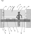
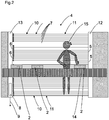
- FIG. 1 shows a light grid 4 for detecting objects 2 and / or persons 15 within a surveillance area 3 or protective field, with a transmitting unit 12 with light beams 7 emitting light emitters 5, with a receiving unit 13 with light beams 7 receiving light receivers 6, and with a control and evaluation 8, in which depending on received signals at the outputs of the light receivers 6 object detection signals 9 are generated, the light emitter 5 and the light receiver 6 are each arranged equidistantly, so that the light emitter 5 and light receiver 6 form a first resolution of the light grating 4, wherein the first resolution in a first region 10 of the light grid 4 is effective and the light emitter 5 and the light receiver 6 are adjustable in a second region 11 of the light grating 4 with a second resolution by the control and evaluation unit 8, the second resolution having a lower resolution is, as the ers te resolution.
- a light grid 4 or light curtain is formed with two different resolutions, wherein a simultaneous monitoring of two different resolutions in a light grid 4 takes place.
- the light grid 4 a distinction between an 'intervention', namely whether only body parts engage in the protective field and an 'access', in which a whole body protrudes into the protective field or the surveillance area 3 of the light grid 4. This distinction is carried out according to the invention by one and the same light grid 4.
- Each of the areas is formed by a certain number of successive light emitters 5 and light receivers 6 as successive emitter / receiver pairs.
- the areas are spatially identical. According to Figure 1 to 4 the first area 10 and the second area 11 extend over the entire light grid 4.
- the object detection signal 9 is output via output switching elements.
- the output switching elements are connected to a machine control.
- the first resolution in the control and evaluation unit is adjustable.
- the first resolution is 14 mm.
- the resolution of 14 mm is intended for finger protection, whereby an intervention with a single finger in the protective field is already detected.
- the first region 10 with the first resolution is extended to the entire protective field.
- the second resolution is 300 mm.
- 300 mm resolution is provided for access protection and after a break again requires actuation of a reset function to enable a restart of the machine.
- the second region 12 with the second resolution also extends over the entire protective field.
- This person 15 monitors a conveyor belt 14 which is arranged in front of the light grid 4 and are transported on the objects 2.
- an intervention in the first area is partially with the head and partially with the left arm of the person 15.
- the conveyor belt 14 is stopped with the objects 2 by the control and evaluation unit 8. If the person 15 leaves the protective field again according to FIG. 3 , the conveyor belt 14 starts again automatically.
- the dangerous movement is also stopped immediately via the object detection signal 9, however, the dangerous movement can only with an operation of a reset function or Reset button to start.
- a restart interlock is provided for the second area 11, so that a restart or restart of the machine with a reset function of a person 15 must be confirmed for this area after the release of the protective field.
- a short interruption can be traced back to the nature of the movement, so that it is a short interruption, for example, a clean bending of the person 15 and a longer interruption of the area, for example, is an occurrence or creeping.
- the control and evaluation unit 8 can be arranged, for example, independently and outside of the light grid housing.
- the control and evaluation unit 8 is formed for example by a secure programmable logic controller. In this controller, the evaluation is performed, for example, via function blocks.
- the light grid 4 is designed as a secure sensor, wherein a communication between the control and evaluation and the light grid 4 is provided.
- the communication can be a secure communication, for example via a secure interface, such as a secure fieldbus.
- control and evaluation unit 8 is arranged together with the light grid 4 in a housing. This makes the light curtain compact and easy to handle.
- the light grid can be connected directly to a machine control or directly to a machine.
- two OSSD pairs ie two redundant switching outputs, are provided, a first redundant switching output being provided for the first region 10 and a second redundant switching output being provided for the second region 11.
Landscapes
- Engineering & Computer Science (AREA)
- General Engineering & Computer Science (AREA)
- Mechanical Engineering (AREA)
- Physics & Mathematics (AREA)
- Life Sciences & Earth Sciences (AREA)
- General Life Sciences & Earth Sciences (AREA)
- General Physics & Mathematics (AREA)
- Geophysics (AREA)
- Geophysics And Detection Of Objects (AREA)
Claims (11)
- Grille lumineuse (4) pour détecter des objets (2) et/ou des personnes (15) à l'intérieur d'une zone à surveiller (3) ou d'un champ de protection, comportant une unité d'émission (12) pourvue d'émetteurs de lumière (5) émettant des faisceaux lumineux (7), une unité de réception (13) pourvue de récepteurs de lumière (6) recevant des faisceaux lumineux (7), et une unité de commande et d'évaluation (8) dans laquelle des signaux de constatation d'objet (8) sont générés en fonction de signaux de réception aux sorties des récepteurs de lumière (6), les émetteurs de lumière (5) et les récepteurs de lumière (6) étant disposés chacun de façon équidistante, les émetteurs de lumière (5) et les récepteurs de lumière (6) formant une première résolution de la grille lumineuse (4),
dans laquelle
la première résolution est efficace dans une première zone (10) de la grille lumineuse (4), et les émetteurs de lumière (5) et les récepteurs de lumière (6) sont susceptibles d'être réglés par l'unité de commande et d'évaluation (8) dans une seconde zone (11) de la grille lumineuse (4) ayant une seconde résolution, la seconde résolution étant une résolution inférieure à la première résolution,
caractérisée en ce que
dans l'unité de commande et d'évaluation (8), des signaux de constatation d'objet (9) respectifs séparés sont formés pour des zones respectives ayant différentes résolutions, et ces signaux de constatation d'objet peuvent être émis via une interface de données, un bus de terrain ou par Ethernet. - Grille lumineuse selon la revendication 1, caractérisée en ce que la première résolution est susceptible d'être réglée dans l'unité de commande et d'évaluation (8).
- Grille lumineuse selon l'une au moins des revendications précédentes, caractérisée en ce que lors d'une intervention dans la zone, un signal d'alerte peut être émis sur une sortie non sécurisée pour la première zone (10) ayant la première résolution et/ou pour la seconde zone (11) ayant la seconde résolution, dans l'unité de commande et d'évaluation (8).
- Grille lumineuse selon l'une au moins des revendications précédentes, caractérisée en ce que la première résolution est d'au moins 14 mm, d'au moins 20 mm, d'au moins 30 mm ou d'au moins 40 mm, la première résolution étant une résolution supérieure à la seconde résolution.
- Grille lumineuse selon l'une au moins des revendications précédentes, caractérisée en ce que la seconde résolution est d'au moins 20 mm, d'au moins 30 mm, d'au moins 40 mm ou d'au moins 300 mm, la seconde résolution étant une résolution inférieure à la première résolution.
- Grille lumineuse selon l'une au moins des revendications précédentes, caractérisée en ce qu'un blocage du redémarrage est prévu pour l'une au moins desdites zones (10, 11), de sorte qu'un démarrage ou un redémarrage de la machine avec fonction de réinitialisation doit être confirmé par une personne (15) pour cette zone, après que le champ de protection est devenu libre.
- Grille lumineuse selon l'une au moins des revendications précédentes, caractérisée en ce qu'un démarrage ou un redémarrage de la machine avec fonction de réinitialisation doit être confirmé par une personne pour la seconde zone (11) ayant la seconde résolution, après que le champ de protection est devenu libre.
- Grille lumineuse selon l'une au moins des revendications précédentes, caractérisée en ce que l'unité de commande et d'évaluation (8) est disposée conjointement avec la grille lumineuse (4) dans un boîtier.
- Grille lumineuse selon l'une au moins des revendications précédentes, caractérisée en ce que les zones (10, 11) sont spatialement différentes.
- Grille lumineuse selon l'une au moins des revendications précédentes 1 à 6, caractérisée en ce que les zones (10, 11) sont spatialement identiques.
- Grille lumineuse selon l'une au moins des revendications précédentes, caractérisée en ce que des signaux de constatation d'objet (9) respectifs séparés sont formés dans l'unité de commande et d'évaluation (8) pour des zones respectives ayant différentes résolutions par deux sorties de commutation redondantes, une première sortie de commutation redondante étant prévue pour la première zone, et une seconde sortie de commutation redondante étant prévue pour la seconde zone.
Applications Claiming Priority (1)
| Application Number | Priority Date | Filing Date | Title |
|---|---|---|---|
| DE102017116396 | 2017-07-20 |
Publications (2)
| Publication Number | Publication Date |
|---|---|
| EP3444519A1 EP3444519A1 (fr) | 2019-02-20 |
| EP3444519B1 true EP3444519B1 (fr) | 2019-12-11 |
Family
ID=62909363
Family Applications (1)
| Application Number | Title | Priority Date | Filing Date |
|---|---|---|---|
| EP18181830.3A Active EP3444519B1 (fr) | 2017-07-20 | 2018-07-05 | Grille lumineuse |
Country Status (2)
| Country | Link |
|---|---|
| EP (1) | EP3444519B1 (fr) |
| DE (1) | DE102018116264B4 (fr) |
Family Cites Families (6)
| Publication number | Priority date | Publication date | Assignee | Title |
|---|---|---|---|---|
| DE10163537A1 (de) * | 2001-12-21 | 2003-07-03 | Sick Ag | Berührungslos wirkende Schutzeinrichtung |
| DE10033077A1 (de) * | 2000-07-07 | 2002-01-17 | Sick Ag | Lichtgitter |
| DE10233258B4 (de) * | 2002-07-23 | 2006-07-13 | Leuze Lumiflex Gmbh + Co. Kg | Lichtgitter |
| DE202006014304U1 (de) | 2006-09-20 | 2007-01-11 | Werac Elektronik Gmbh | Lichtgitter zur Absicherung von Gefahrenstellen |
| DE102008004941B4 (de) * | 2008-01-18 | 2009-10-22 | Sick Ag | Sicherheitsanordnung und Verfahren |
| DE102014102837B3 (de) * | 2014-03-04 | 2015-05-28 | Sick Ag | Vorrichtung zur Werkzeugkontrolle |
-
2018
- 2018-07-05 EP EP18181830.3A patent/EP3444519B1/fr active Active
- 2018-07-05 DE DE102018116264.2A patent/DE102018116264B4/de not_active Expired - Fee Related
Non-Patent Citations (1)
| Title |
|---|
| None * |
Also Published As
| Publication number | Publication date |
|---|---|
| EP3444519A1 (fr) | 2019-02-20 |
| DE102018116264B4 (de) | 2021-05-06 |
| DE102018116264A1 (de) | 2019-01-24 |
Similar Documents
| Publication | Publication Date | Title |
|---|---|---|
| EP1367314B1 (fr) | Dispositif de surveillance du champ d'action d'un organe de travail | |
| EP1635107B2 (fr) | Procédé et dispositif de commande d'une fonction de sécurité d'une machine | |
| EP1418380B1 (fr) | Procédé et dispositif pour surveiller une zone | |
| EP2180348B1 (fr) | Barrière lumineuse de sécurité et procédé correspondant de surveillance d'une zone de protection | |
| EP1353196B1 (fr) | Détection d'un objet et barrière optique | |
| DE102008050943B4 (de) | Optischer Sensor | |
| EP3696461B1 (fr) | Dispositif de sécurisation pour une machine et procédé de fonctionnement | |
| EP1443343B1 (fr) | Détecteur optique avec plusiers sorties de commutation | |
| DE102007033766A1 (de) | Lichtgitter | |
| EP3415804B1 (fr) | Dispositif de sécurité | |
| DE10327388B4 (de) | Schutzeinrichtung | |
| EP3882505B1 (fr) | Dispositif de surveillance et procédé de fonctionnement d'un dispositif de surveillance | |
| EP2853929A1 (fr) | Capteur de sécurité opto-électronique | |
| EP3133331B1 (fr) | Systeme de securite et procede de surveillance | |
| EP3447540B1 (fr) | Rideau lumineux | |
| EP3594553B1 (fr) | Dispositif de surveillance d'une zone de danger | |
| DE102019119137B4 (de) | Sicherungsvorrichtung für eine Maschine und Verfahren zum Betreiben einer Sicherungsvorrichtung | |
| EP3754243B1 (fr) | Dispositif de sécurisation d'une zone dangereuse | |
| EP3444519A1 (fr) | Grille lumineuse | |
| DE102009031226B4 (de) | Sicherheitslichtgitter | |
| EP3640522A1 (fr) | Dispositif de surveillance | |
| EP3627033B1 (fr) | Dispositif de sécurisation d'une zone à risque d'une installation | |
| EP3889487A1 (fr) | Système d'alerte pour la surveillance d'une zone de protection et de détection dans l'environnement d'une source de danger | |
| DE102023120220B4 (de) | Sicherheitssystem zur Absicherung eines Aktionsbereichs einer Produktionsanlage | |
| EP3757443B1 (fr) | Élément de surveillance et procédé de sécurisation de zones dangereuses |
Legal Events
| Date | Code | Title | Description |
|---|---|---|---|
| PUAI | Public reference made under article 153(3) epc to a published international application that has entered the european phase |
Free format text: ORIGINAL CODE: 0009012 |
|
| STAA | Information on the status of an ep patent application or granted ep patent |
Free format text: STATUS: THE APPLICATION HAS BEEN PUBLISHED |
|
| AK | Designated contracting states |
Kind code of ref document: A1 Designated state(s): AL AT BE BG CH CY CZ DE DK EE ES FI FR GB GR HR HU IE IS IT LI LT LU LV MC MK MT NL NO PL PT RO RS SE SI SK SM TR |
|
| AX | Request for extension of the european patent |
Extension state: BA ME |
|
| STAA | Information on the status of an ep patent application or granted ep patent |
Free format text: STATUS: REQUEST FOR EXAMINATION WAS MADE |
|
| 17P | Request for examination filed |
Effective date: 20190516 |
|
| RBV | Designated contracting states (corrected) |
Designated state(s): AL AT BE BG CH CY CZ DE DK EE ES FI FR GB GR HR HU IE IS IT LI LT LU LV MC MK MT NL NO PL PT RO RS SE SI SK SM TR |
|
| RIC1 | Information provided on ipc code assigned before grant |
Ipc: G01V 8/20 20060101ALI20190605BHEP Ipc: F16P 3/14 20060101AFI20190605BHEP |
|
| GRAP | Despatch of communication of intention to grant a patent |
Free format text: ORIGINAL CODE: EPIDOSNIGR1 |
|
| STAA | Information on the status of an ep patent application or granted ep patent |
Free format text: STATUS: GRANT OF PATENT IS INTENDED |
|
| INTG | Intention to grant announced |
Effective date: 20190821 |
|
| GRAS | Grant fee paid |
Free format text: ORIGINAL CODE: EPIDOSNIGR3 |
|
| GRAA | (expected) grant |
Free format text: ORIGINAL CODE: 0009210 |
|
| STAA | Information on the status of an ep patent application or granted ep patent |
Free format text: STATUS: THE PATENT HAS BEEN GRANTED |
|
| AK | Designated contracting states |
Kind code of ref document: B1 Designated state(s): AL AT BE BG CH CY CZ DE DK EE ES FI FR GB GR HR HU IE IS IT LI LT LU LV MC MK MT NL NO PL PT RO RS SE SI SK SM TR |
|
| REG | Reference to a national code |
Ref country code: GB Ref legal event code: FG4D Free format text: NOT ENGLISH |
|
| REG | Reference to a national code |
Ref country code: CH Ref legal event code: EP |
|
| REG | Reference to a national code |
Ref country code: AT Ref legal event code: REF Ref document number: 1212544 Country of ref document: AT Kind code of ref document: T Effective date: 20191215 |
|
| REG | Reference to a national code |
Ref country code: DE Ref legal event code: R096 Ref document number: 502018000492 Country of ref document: DE |
|
| REG | Reference to a national code |
Ref country code: IE Ref legal event code: FG4D Free format text: LANGUAGE OF EP DOCUMENT: GERMAN |
|
| RAP2 | Party data changed (patent owner data changed or rights of a patent transferred) |
Owner name: SICK AG |
|
| REG | Reference to a national code |
Ref country code: NL Ref legal event code: MP Effective date: 20191211 |
|
| REG | Reference to a national code |
Ref country code: LT Ref legal event code: MG4D |
|
| PG25 | Lapsed in a contracting state [announced via postgrant information from national office to epo] |
Ref country code: FI Free format text: LAPSE BECAUSE OF FAILURE TO SUBMIT A TRANSLATION OF THE DESCRIPTION OR TO PAY THE FEE WITHIN THE PRESCRIBED TIME-LIMIT Effective date: 20191211 Ref country code: GR Free format text: LAPSE BECAUSE OF FAILURE TO SUBMIT A TRANSLATION OF THE DESCRIPTION OR TO PAY THE FEE WITHIN THE PRESCRIBED TIME-LIMIT Effective date: 20200312 Ref country code: NO Free format text: LAPSE BECAUSE OF FAILURE TO SUBMIT A TRANSLATION OF THE DESCRIPTION OR TO PAY THE FEE WITHIN THE PRESCRIBED TIME-LIMIT Effective date: 20200311 Ref country code: BG Free format text: LAPSE BECAUSE OF FAILURE TO SUBMIT A TRANSLATION OF THE DESCRIPTION OR TO PAY THE FEE WITHIN THE PRESCRIBED TIME-LIMIT Effective date: 20200311 Ref country code: SE Free format text: LAPSE BECAUSE OF FAILURE TO SUBMIT A TRANSLATION OF THE DESCRIPTION OR TO PAY THE FEE WITHIN THE PRESCRIBED TIME-LIMIT Effective date: 20191211 Ref country code: LV Free format text: LAPSE BECAUSE OF FAILURE TO SUBMIT A TRANSLATION OF THE DESCRIPTION OR TO PAY THE FEE WITHIN THE PRESCRIBED TIME-LIMIT Effective date: 20191211 Ref country code: LT Free format text: LAPSE BECAUSE OF FAILURE TO SUBMIT A TRANSLATION OF THE DESCRIPTION OR TO PAY THE FEE WITHIN THE PRESCRIBED TIME-LIMIT Effective date: 20191211 |
|
| PG25 | Lapsed in a contracting state [announced via postgrant information from national office to epo] |
Ref country code: RS Free format text: LAPSE BECAUSE OF FAILURE TO SUBMIT A TRANSLATION OF THE DESCRIPTION OR TO PAY THE FEE WITHIN THE PRESCRIBED TIME-LIMIT Effective date: 20191211 Ref country code: HR Free format text: LAPSE BECAUSE OF FAILURE TO SUBMIT A TRANSLATION OF THE DESCRIPTION OR TO PAY THE FEE WITHIN THE PRESCRIBED TIME-LIMIT Effective date: 20191211 |
|
| PG25 | Lapsed in a contracting state [announced via postgrant information from national office to epo] |
Ref country code: AL Free format text: LAPSE BECAUSE OF FAILURE TO SUBMIT A TRANSLATION OF THE DESCRIPTION OR TO PAY THE FEE WITHIN THE PRESCRIBED TIME-LIMIT Effective date: 20191211 |
|
| PG25 | Lapsed in a contracting state [announced via postgrant information from national office to epo] |
Ref country code: NL Free format text: LAPSE BECAUSE OF FAILURE TO SUBMIT A TRANSLATION OF THE DESCRIPTION OR TO PAY THE FEE WITHIN THE PRESCRIBED TIME-LIMIT Effective date: 20191211 Ref country code: ES Free format text: LAPSE BECAUSE OF FAILURE TO SUBMIT A TRANSLATION OF THE DESCRIPTION OR TO PAY THE FEE WITHIN THE PRESCRIBED TIME-LIMIT Effective date: 20191211 Ref country code: EE Free format text: LAPSE BECAUSE OF FAILURE TO SUBMIT A TRANSLATION OF THE DESCRIPTION OR TO PAY THE FEE WITHIN THE PRESCRIBED TIME-LIMIT Effective date: 20191211 Ref country code: CZ Free format text: LAPSE BECAUSE OF FAILURE TO SUBMIT A TRANSLATION OF THE DESCRIPTION OR TO PAY THE FEE WITHIN THE PRESCRIBED TIME-LIMIT Effective date: 20191211 Ref country code: RO Free format text: LAPSE BECAUSE OF FAILURE TO SUBMIT A TRANSLATION OF THE DESCRIPTION OR TO PAY THE FEE WITHIN THE PRESCRIBED TIME-LIMIT Effective date: 20191211 Ref country code: PT Free format text: LAPSE BECAUSE OF FAILURE TO SUBMIT A TRANSLATION OF THE DESCRIPTION OR TO PAY THE FEE WITHIN THE PRESCRIBED TIME-LIMIT Effective date: 20200506 |
|
| PG25 | Lapsed in a contracting state [announced via postgrant information from national office to epo] |
Ref country code: SM Free format text: LAPSE BECAUSE OF FAILURE TO SUBMIT A TRANSLATION OF THE DESCRIPTION OR TO PAY THE FEE WITHIN THE PRESCRIBED TIME-LIMIT Effective date: 20191211 Ref country code: SK Free format text: LAPSE BECAUSE OF FAILURE TO SUBMIT A TRANSLATION OF THE DESCRIPTION OR TO PAY THE FEE WITHIN THE PRESCRIBED TIME-LIMIT Effective date: 20191211 Ref country code: IS Free format text: LAPSE BECAUSE OF FAILURE TO SUBMIT A TRANSLATION OF THE DESCRIPTION OR TO PAY THE FEE WITHIN THE PRESCRIBED TIME-LIMIT Effective date: 20200411 |
|
| REG | Reference to a national code |
Ref country code: DE Ref legal event code: R097 Ref document number: 502018000492 Country of ref document: DE |
|
| PLBE | No opposition filed within time limit |
Free format text: ORIGINAL CODE: 0009261 |
|
| STAA | Information on the status of an ep patent application or granted ep patent |
Free format text: STATUS: NO OPPOSITION FILED WITHIN TIME LIMIT |
|
| PG25 | Lapsed in a contracting state [announced via postgrant information from national office to epo] |
Ref country code: DK Free format text: LAPSE BECAUSE OF FAILURE TO SUBMIT A TRANSLATION OF THE DESCRIPTION OR TO PAY THE FEE WITHIN THE PRESCRIBED TIME-LIMIT Effective date: 20191211 |
|
| 26N | No opposition filed |
Effective date: 20200914 |
|
| PG25 | Lapsed in a contracting state [announced via postgrant information from national office to epo] |
Ref country code: SI Free format text: LAPSE BECAUSE OF FAILURE TO SUBMIT A TRANSLATION OF THE DESCRIPTION OR TO PAY THE FEE WITHIN THE PRESCRIBED TIME-LIMIT Effective date: 20191211 |
|
| PG25 | Lapsed in a contracting state [announced via postgrant information from national office to epo] |
Ref country code: MC Free format text: LAPSE BECAUSE OF FAILURE TO SUBMIT A TRANSLATION OF THE DESCRIPTION OR TO PAY THE FEE WITHIN THE PRESCRIBED TIME-LIMIT Effective date: 20191211 Ref country code: PL Free format text: LAPSE BECAUSE OF FAILURE TO SUBMIT A TRANSLATION OF THE DESCRIPTION OR TO PAY THE FEE WITHIN THE PRESCRIBED TIME-LIMIT Effective date: 20191211 |
|
| REG | Reference to a national code |
Ref country code: BE Ref legal event code: MM Effective date: 20200731 |
|
| PG25 | Lapsed in a contracting state [announced via postgrant information from national office to epo] |
Ref country code: IE Free format text: LAPSE BECAUSE OF NON-PAYMENT OF DUE FEES Effective date: 20200705 Ref country code: LU Free format text: LAPSE BECAUSE OF NON-PAYMENT OF DUE FEES Effective date: 20200705 |
|
| PG25 | Lapsed in a contracting state [announced via postgrant information from national office to epo] |
Ref country code: BE Free format text: LAPSE BECAUSE OF NON-PAYMENT OF DUE FEES Effective date: 20200731 |
|
| PG25 | Lapsed in a contracting state [announced via postgrant information from national office to epo] |
Ref country code: TR Free format text: LAPSE BECAUSE OF FAILURE TO SUBMIT A TRANSLATION OF THE DESCRIPTION OR TO PAY THE FEE WITHIN THE PRESCRIBED TIME-LIMIT Effective date: 20191211 Ref country code: MT Free format text: LAPSE BECAUSE OF FAILURE TO SUBMIT A TRANSLATION OF THE DESCRIPTION OR TO PAY THE FEE WITHIN THE PRESCRIBED TIME-LIMIT Effective date: 20191211 Ref country code: CY Free format text: LAPSE BECAUSE OF FAILURE TO SUBMIT A TRANSLATION OF THE DESCRIPTION OR TO PAY THE FEE WITHIN THE PRESCRIBED TIME-LIMIT Effective date: 20191211 |
|
| PG25 | Lapsed in a contracting state [announced via postgrant information from national office to epo] |
Ref country code: MK Free format text: LAPSE BECAUSE OF FAILURE TO SUBMIT A TRANSLATION OF THE DESCRIPTION OR TO PAY THE FEE WITHIN THE PRESCRIBED TIME-LIMIT Effective date: 20191211 |
|
| PGFP | Annual fee paid to national office [announced via postgrant information from national office to epo] |
Ref country code: DE Payment date: 20250722 Year of fee payment: 8 |
|
| PGFP | Annual fee paid to national office [announced via postgrant information from national office to epo] |
Ref country code: IT Payment date: 20250731 Year of fee payment: 8 |
|
| PGFP | Annual fee paid to national office [announced via postgrant information from national office to epo] |
Ref country code: GB Payment date: 20250724 Year of fee payment: 8 |
|
| PGFP | Annual fee paid to national office [announced via postgrant information from national office to epo] |
Ref country code: AT Payment date: 20250721 Year of fee payment: 8 Ref country code: FR Payment date: 20250723 Year of fee payment: 8 |
|
| PGFP | Annual fee paid to national office [announced via postgrant information from national office to epo] |
Ref country code: CH Payment date: 20250801 Year of fee payment: 8 |