EP3444573B1 - Tête à ultrasons pour un débitmètre dotée de moyens d'extraction - Google Patents
Tête à ultrasons pour un débitmètre dotée de moyens d'extraction Download PDFInfo
- Publication number
- EP3444573B1 EP3444573B1 EP18188733.2A EP18188733A EP3444573B1 EP 3444573 B1 EP3444573 B1 EP 3444573B1 EP 18188733 A EP18188733 A EP 18188733A EP 3444573 B1 EP3444573 B1 EP 3444573B1
- Authority
- EP
- European Patent Office
- Prior art keywords
- pot
- transducer
- closure part
- sound
- collar
- Prior art date
- Legal status (The legal status is an assumption and is not a legal conclusion. Google has not performed a legal analysis and makes no representation as to the accuracy of the status listed.)
- Active
Links
Images


Classifications
-
- G—PHYSICS
- G01—MEASURING; TESTING
- G01F—MEASURING VOLUME, VOLUME FLOW, MASS FLOW OR LIQUID LEVEL; METERING BY VOLUME
- G01F1/00—Measuring the volume flow or mass flow of fluid or fluent solid material wherein the fluid passes through a meter in a continuous flow
- G01F1/66—Measuring the volume flow or mass flow of fluid or fluent solid material wherein the fluid passes through a meter in a continuous flow by measuring frequency, phase shift or propagation time of electromagnetic or other waves, e.g. using ultrasonic flowmeters
- G01F1/662—Constructional details
-
- G—PHYSICS
- G01—MEASURING; TESTING
- G01F—MEASURING VOLUME, VOLUME FLOW, MASS FLOW OR LIQUID LEVEL; METERING BY VOLUME
- G01F1/00—Measuring the volume flow or mass flow of fluid or fluent solid material wherein the fluid passes through a meter in a continuous flow
- G01F1/66—Measuring the volume flow or mass flow of fluid or fluent solid material wherein the fluid passes through a meter in a continuous flow by measuring frequency, phase shift or propagation time of electromagnetic or other waves, e.g. using ultrasonic flowmeters
- G01F1/667—Arrangements of transducers for ultrasonic flowmeters; Circuits for operating ultrasonic flowmeters
Definitions
- the invention relates to a transducer for installation in a measuring tube of a flow meter for sound-based detection of a flow rate of a medium.
- Pulse-shaped (ultra) sound signals are generated by means of (ultra) sound transducers and transmitted in the flow direction and against the flow direction through the medium. The difference in the transit times of the sound signals in both directions is evaluated to determine the flow rate of the medium.
- Such ultrasound-based flow meters work according to the time difference principle.
- the sound transducers used for sound generation and sound reception can also be installed in separate components.
- the sound transducer can be located in a separate housing.
- a separate housing Such a unit consisting of a housing with a sound transducer placed therein is also referred to here as a transducer.
- the housing can be made very stable, for example as a brass component. Then the transducer can withstand very high pressure loads from the medium to be detected. On the other hand, however, there are also comparatively high manufacturing costs and a high weight.
- a transducer which comprises a metallic pot with a pot side wall, a pot base to be sonicated and a pot opening opposite the pot base.
- a piezo element is glued to the inside of the pot base by means of an acoustic coupling layer.
- An elastically deformable connecting band is provided for the electrical contacting of the piezo element.
- a housing is inserted in the pot and closes the pot opening. This case has a protective collar on the top, which protrudes beyond the closed pot opening, surrounds the connecting band and is equipped with an undercut.
- the object of the invention is to provide a transducer for installation in a flow meter, which is further improved compared to the known designs.
- the transducer according to the invention has a pot made of a metallic pot material with a pot side wall, a pot bottom to be sounded through and a pot opening opposite the pot bottom, an electromechanical sound conversion element which is glued to an inside of the pot bottom, two electrical leads leading out of the pot opening for electrical contacting of the electromechanical Sound conversion element, and a closure part which is inserted into the pot and closes the pot opening.
- the closure part has a protective collar on a side facing away from the electromechanical sound conversion element, which protrudes beyond the closed pot opening and surrounds the electrical feed lines, the protective collar being equipped with pull-out means.
- the electrical feed lines have exposed end sections
- the protective collar extends in the axial direction at least as far as the exposed end sections of the electrical feed lines.
- the pull-out means are designed as at least one through opening present in a collar wall of the protective collar.
- the pot is in particular a deep-drawn component and can accordingly be manufactured inexpensively.
- the pot material is also preferably electrically conductive. It is in particular a metal and consists e.g. made of a stainless steel or has at least a stainless steel portion.
- the pot is in particular made in one piece.
- the pot side wall and the bottom of the pot are integrally connected. They are made of the same material. Accordingly, there is a substance bond between them.
- the bottom of the pot which faces the medium to be detected when the transducer is installed in a measuring tube and in particular also comes into direct contact with the medium, is closed by the bottom of the pot. In the installed state, the pot securely encapsulates the inside of the pot and the components therein, in particular — but not only — the electromechanical sound conversion element from the medium to be detected or sonicated.
- the electromechanical sound conversion element is preferably glued to the inside of the pot base. This ensures in particular that the bottom of the pot is essentially together with the electromechanical Sound conversion element vibrates and that sound energy is thus radiated into the medium via the pot bottom and, conversely, is also transmitted from the medium to the sound conversion element.
- the pot bottom and the glued or glued electromechanical sound conversion element form a cheap sound combination unit.
- the medium is a liquid medium, preferably water.
- the transducer is especially designed to sonicate this medium.
- the protective collar advantageously protects the end sections of the electrical feed lines which are surrounded by it.
- the protective collar extends in the axial direction, that is to say in the direction of the longitudinal axis of the transducer, at least approximately as far as the exposed ends of the electrical leads, which are thus essentially completely surrounded by the protective collar.
- the protective collar in particular prevents mechanical damage to the exposed ends of the electrical feed lines and thereby ensures that the free ends of the electrical feed lines intended for signal connection are always in the correct position, which was originally set during manufacture, and remain there.
- the transducer can preferably be installed automatically in a measuring system.
- the pull-out means in the protective collar make it easier to disassemble the transducer from its installation position in a measuring tube.
- a suitably designed removal tool can in particular be inserted in order to then advantageously pull the transducer out of its installation position with little effort.
- the pull-out means are designed as two through openings which are present in a collar wall of the protective collar and which are aligned with one another. This further simplifies the removal of the transducer from its installation position. If the pulling tool engages in two mutually aligned through openings, a pull-out force acting essentially parallel to the longitudinal axis of the transducer is applied, so that there is no tilting of the transducer during the extraction of the transducer comes, which would otherwise make removal from the installation position difficult.
- the closure part is placed within the pot in such a way that it exerts pressure on the electromechanical sound conversion element.
- This pressure can in particular be applied directly or indirectly, for example by means of an in particular compressible damping body. This results in a permanently stable structure that guarantees consistently good functionality of the transducer over a long period of time.
- the pressurization also ensures constant damping and a controlled manufacturing process.
- the closure part has a laterally projecting and completely circumferential connecting collar, which is firmly connected to a particularly deformed or bent edge region of the pot side wall.
- the connection between the connecting collar and the edge region of the pot side wall is preferably an adhesive connection or a welded connection. This provides very good protection against external interference. In particular, the connection is very tight against the ingress of dust, dirt and / or water or other liquids.
- the closure part has a plastic main body and a reinforcing plate, at least some of the reinforcing plate being embedded in the plastic main body.
- the protective collar is in particular a component of the plastic main body and is preferably on a side of the reinforcement plate facing away from the electromechanical sound conversion element arranged.
- the pot has in particular a pot wall thickness in the range between 0.1 mm and 1 mm, preferably between 0.2 mm and 0.5 mm. These thickness values apply in particular to both the pot side wall and the pot base. In any case, it is not a particularly large pot wall thickness. In this respect, the pot is only mechanically resilient to a limited extent. This applies in particular to the embodiment as a deep-drawing component.
- the reinforcing plate of the closure part leads to an advantageous mechanical relief of the pot, in particular of its pot side wall and / or of its pot base.
- the reinforcing plate has a plate thickness of preferably in the range between 0.5 mm to 5 mm, in particular in the range between 0.75 mm to 3 mm.
- the latter is particularly advantageous when the medium to be detected or sonicated by means of the transducer is under high pressure, for example in normal operation under a pressure of more than 10 bar, preferably in the range between about 16 bar and about 25 bar. In special operating situations, pressure peaks with even higher pressure values of up to 50 bar in particular can occur with flowmeters.
- the plastic main body of the closure part is not primarily intended to increase the mechanical stability, although in principle it also contributes to this to a certain extent.
- the plastic main body mainly serves to close the pot opening, but also to guide the electrical leads and in particular also to protect the exposed end sections of the electrical leads.
- the reinforcement plate and the plastic main body, as the two components of the closure part in particular each perform specific and different tasks, according to which they are preferably designed in a targeted manner are.
- the plastic main body is used in particular to save weight compared to a purely metallic embodiment. Therefore, the closure part, which is composed of two components, offers particular advantages over a one-piece embodiment with only one component.
- the reinforcing plate extends into the connecting collar and forms a closure part connecting surface there, which is connected to a corresponding pot connecting surface present in the edge region of the pot side wall.
- the connecting collar is essentially formed by the reinforcing plate.
- the closure part connecting surface is an exposed part of the surface of the reinforcing plate, which is uncovered in this area, that is to say not embedded in the plastic material of the plastic main body.
- the pot side wall has a pot step and the closure part in a closure part side wall has a closure part step corresponding to the pot step, the pot step and the closure part step directly abutting one another.
- the advantageously stepped pot side wall in combination with the likewise advantageously stepped closure part side wall, offers a particularly high resistance to high pressures which can arise during operation due to contact with the medium.
- the medium is a liquid transported in a pipe system, which means that considerable pressure loads can be transmitted through the medium to the transducer.
- the transducer is preferably for use designed in such a (possibly under high pressure) liquid medium.
- the adjoining steps advantageously take up the pressure loads and dissipate them, so that the electromechanical sound transducer element placed on the pot base is protected from mechanical damage.
- the adjacent steps during the manufacture of the transducer advantageously serve as an end stop for how far the closure part is to be inserted into the pot. In this way, the design specifications can be adhered to very easily and, above all, very reliably. In particular, this ensures that the closure part (directly or indirectly) exerts the precisely desired pressure on the electromechanical sound conversion element and / or that a first adhesive layer between the electromechanical sound conversion element and the pot base has the desired layer thickness.
- the outside of the pot step can be used to place the retaining webs of a sound reflector on the step edge, which deflects a sound signal emanating from the sound head or an incoming sound signal onto the sound head.
- the pot step is therefore in particular also an attachment or attachment point for such a sound reflector.
- an electrically insulating first adhesive layer is present for gluing between the electromechanical sound conversion element and the pot base.
- the first adhesive layer forms the bond between the electromechanical sound conversion element and the pot base.
- the galvanic separation inherently given due to the preferably electrically insulating first adhesive layer between the electromechanical sound conversion element including its electrical leads on the one hand and the in particular metallic and thus electrically conductive pot on the other hand simplifies the electrical connection of the transducer to an energy supply and / or to a control / Evaluation unit.
- the additional component for galvanic isolation such as an optocoupler, which is otherwise present in such an electrical connection, can be omitted, which offers cost advantages for an overall measuring system implemented with the transducer.
- the electrically insulating first adhesive layer has mechanically stable spacing elements, in particular in the form of glass beads.
- these glass spheres are also electrically insulating. They ensure that a desired minimum insulation distance between the electromechanical sound conversion element and the pot base is preferably given everywhere.
- the spacer elements can in particular also be referred to as "spacers”.
- the electrically insulating first adhesive layer has a layer thickness in the range between 5 ⁇ m and 300 ⁇ m, in particular between 10 ⁇ m and 200 ⁇ m. This achieves a very good compromise between two opposite trends. The greater the layer thickness of the first adhesive layer the more stable the mechanical properties are. On the other hand, an excessively thick first adhesive layer makes it difficult or impossible for the electromechanical sound transducer element or the bonded composite of the electromechanical sound transducer element and the base of the pot to vibrate, which is decisive for the main function of the transducer to generate and receive sound. Layer thicknesses from the above-mentioned value ranges are equally well suited to both aspects.
- the closure part and the pot side wall are connected to one another by means of a second adhesive layer.
- This second layer of adhesive serves to protect against the ingress of dust, other dirt, water, other liquids and / or gases into the interior of the pot, in which the relevant components of the transducer are located.
- the transducer is a combination component that cannot be dismantled in particular. The latter is easier to handle and install with less susceptibility to errors.
- the first and the second adhesive layer have the same curing conditions, in particular the same curing time, the same curing temperature and the same curing pressure. Both adhesive layers can then advantageously be cured simultaneously, which shortens the production time.
- the first and the second adhesive layer can for example consist of an epoxy adhesive or have such a material component. It is possible, but not absolutely necessary, that both adhesive layers consist of the same adhesive or at least on that based on the same adhesive. A conceivable difference is that, in contrast to the first adhesive layer, the second adhesive layer has no additional component in the form of the spacer elements.
- the second adhesive layer can also be designed to be electrically insulating. However, this is not absolutely necessary and offers no comparable advantages as with the first adhesive layer.
- the pot has a pot wall thickness between 0.1 mm and 1 mm, preferably between 0.2 mm and 0.5 mm. These thickness values apply in particular to both the pot side wall and the pot base. In any case, it is not a particularly large pot wall thickness. In this respect, the pot is only mechanically resilient to a limited extent. Nevertheless, the transducer is mechanically stable overall, which is particularly due to the reinforcement plate. The comparatively low pot wall thickness saves material and thus costs. This also results in a preferably relatively low total weight of the transducer.
- a reinforcing sheet with a sheet thickness from the above-mentioned particularly favorable value ranges preferably relieves the pot very efficiently.
- the reinforcement plate is a stamped metal disk. This can be produced very easily, quickly and inexpensively.
- the reinforcement plate has a central through opening, through which the plastic main body and the electrical feed lines extend.
- This geometry of the reinforcement plate is favorable because, on the one hand, it allows the electrical feed lines to be passed through without, on the other hand, significantly reducing the mechanical stabilizing effect of the reinforcement plate.
- the reinforcement plate has several decentralized through openings which are filled with the plastic material of the plastic main body. This results in a particularly stable and intimate connection between the reinforcement plate and the plastic main body.
- the reinforcement plate is extrusion-coated with the plastic material of the plastic main body, so that a combined structural unit is formed from the plastic main body and the reinforcement plate.
- a combined structural unit is formed from the plastic main body and the reinforcement plate.
- the reinforcement plate is arranged parallel to the electromechanical sound conversion element. Then the reinforcement plate contributes particularly well to the protection of the electromechanical sound conversion element as the key component of the transducer and to the mechanical stability of the transducer as a whole.
- the structure of the transducer is very safely protected against damage.
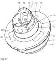
- a transducer 1 is shown, which is intended for installation in a measuring tube of a flow meter for sound-based detection of a flow rate of a medium.
- the measuring tube can be, for example, a valve housing.
- the transducer 1 is characterized by simple installation, which advantageously enables a very assembly-friendly, in particular fully automated, manufacturing process. In this way, large quantities of the transducer 1 can be produced at a comparatively low cost and with a comparatively short production time.
- the transducer 1 has a longitudinal axis 2.
- the transducer 1 is essentially rotationally symmetrical with respect to the longitudinal axis 2.
- this is not absolutely necessary.
- Other cross-sectional geometries for example a cross-sectional geometry that is essentially square or rectangular with respect to the longitudinal axis 2, are also possible.
- the transducer 1 comprises several subcomponents, such as a pot 3 made of a metallic, electrically conductive pot material, for example made of stainless steel.
- the pot 3 is in particular a deep-drawn component. It has a particularly stepped pot side wall 4 and a pot base 5.
- the pot base 5 is opposite a pot opening 6.
- the pot side wall 4 has a pot step 7.
- the pot side wall 4 opens out at the level of the pot opening 6 into a pot edge region 8, which is deformed in particular during the deep-drawing process and which extends away from the side the longitudinal axis 2 extends.
- a surface normal of the pot edge area 8 is essentially parallel to the longitudinal axis 2. With a rotationally symmetrical geometry of the transducer 1, the pot edge area 8 projects or protrudes radially. Regardless of the external geometric shape of the transducer 1, the pot edge area 8 surrounds the pot opening 6, in particular over its entire circumference.
- the transducer 1 has an electromechanical sound conversion element 9.
- the latter is the key component for the sound-receiving and / or sound-transmitting function of the transducer 1.
- the electromechanical sound conversion element 9 is glued to the inside of the pot base 5. It has a flat piezoelectric plate 10 with a flat top and bottom, both of which are oriented essentially perpendicular to the longitudinal axis 2.
- the top and bottom of the piezoelectric plate 10 are each provided with an electrode 11 or 12, the electrode 12 arranged on the underside in the area of a lateral recess 13 of the piezoelectric plate 10 over the edge of the piezoelectric plate 10 up to Top is pulled (see Fig. 4 ).
- the electrode 11 provided on the top has a recess in this area and does not extend there, so that there is an insulation distance between the portion of the electrode 12 drawn up from the bottom and the electrode 11 on the top.
- the lateral recess 13 also serves to position the electromechanical sound conversion element 9 on the pot base 5, in particular in an automated, correct position.
- the pot 3 is a one-piece deep-drawn component.
- the pot side wall 4 and the pot base 5 are thus connected to one another in one piece. They are made of the same material. Accordingly lies a substance connection between them.
- the pot 3 is closed by the pot bottom 5 on its underside facing the medium to be detected when it is installed in the measuring tube. In the installed state, the pot 3 securely encapsulates the inside of the pot 3 and the components therein from the medium to be detected, the medium flowing directly past the outside of the bottom of the pot bottom 5.
- the transducer 1 is in particular to be inserted into a through opening of the measuring tube and thus comes into contact on its underside with the medium to be detected.
- the transducer 1 has two electrical leads 14 and 15, by means of which the two electrodes 11 and 12 are electrically contacted.
- the damping element 16 consists of an elastomer, for example Viton. It is compressible to a certain extent and, in the compressed state, exerts a pressing force on the electromechanical sound conversion element 9 and on the bent sections of the spring contact pins of the electrical leads 14 and 15, which are thereby pressed onto the respective electrical contact points on the electrodes 11 and 12.
- the damping element 16 is also a component of the transducer 1.
- the closure part 17 is the load-bearing component which, in addition to closing the pot opening 6, also primarily to ensure mechanical stability of the transducer 1 serves as a whole. It is a composite component that is composed of a plastic main body 18 and a reinforcing plate 19.
- the reinforcement plate 19, which is in particular metallic, is partially embedded in the plastic main body 18. Some of it is extrusion-coated with the plastic of the plastic main body 18. This encapsulation or injection of the reinforcement plate 19 with the plastic of the plastic main body 18 takes place in particular by means of an advantageously automated injection molding process. At the end of this injection molding process, the closure part 17 is present as a composite component.
- FIG Fig. 6 A top view of the reinforcement plate 19 (not yet overmolded with plastic) is shown in FIG Fig. 6 shown. It contains a central through opening 20 and three further edge openings 21, 22, 23 which are evenly distributed in the circumferential direction and which can also be understood as decentralized through openings. The latter are filled with the plastic of the plastic main body 18, so that an intimate connection between these two sub-components results. In the area of the central through opening 20, the electrical feed lines 14, 15 are led through the reinforcing plate 19 with their feed sections. Otherwise, the plastic of the plastic main body 18 also extends through the central through opening 20, which further increases the bond strength.
- the closure part 17 is inserted into the pot 3 with an inner part 24 of the plastic main body 18.
- the inner part 24 laterally surrounds the damping element 16 and at least partially also the electromechanical sound converting element 9. From above, the closure part 17 exerts pressure on the damping element 16, so that the latter is compressed.
- the closure part 17 has 24 in the area of its inner part a closure part side wall 25 which is provided with a closure part step 26 corresponding to the pot step 7.
- the pot level 7 and the closure part level 26 are in direct contact with one another in the final assembled state of the transducer 1.
- the reinforcing plate 19 is arranged above the inner part 24 with its closure part side wall 25. It forms a laterally projecting and completely circumferential connecting collar 27 of the closure part 17 and is firmly connected to the pot edge area 8, glued in the exemplary embodiment shown.
- the connecting collar 27 projects laterally beyond the closure part side wall 25.
- the reinforcing plate 19 has a closure part connecting surface 28 which is connected, in particular glued, to a corresponding pot connecting surface 29 present in the pot edge area 8. The connection is made between two metal components and is therefore particularly stable and stable.
- the reinforcing plate 19 of the closure part 17 is used for mechanical reinforcement, which is particularly advantageous when the medium to be detected by the transducer 1 is under high pressure.
- pressure values in the range between approximately 16 bar to approximately 25 bar can occur when used in a liquid medium in normal operation.
- pressure peaks in the range between about 24 bar to about 50 bar can even occur.
- the reinforcement plate 19 prevents undesired bending of the transducer 1 and, in particular, of the electromechanical transducer element 9 contained therein, so that the full functionality is maintained even at such high pressure values, although the pot 3, which represents the outer shell, is only a deep-drawn component with a comparatively small pot wall thickness.
- the Pot wall thickness of the pot 3 is, for example, only between approximately 0.25 mm and 0.45 mm. Nevertheless, the mechanical stability remains guaranteed, which is achieved in particular due to the reinforcement plate 19. In addition to damage to the transducer 1, the reinforcement plate 19 also prevents leakage at the location in the pipeline system carrying the medium at which the transducer 1 is used, for example because of a deformation of the outer contour of the transducer 1 that is otherwise possible under high pressures.
- the closure part step 26 resting on the pot step 7 also serves for stabilization. It absorbs part of the pressure exerted by the medium and passes it on to the reinforcing plate 19.
- a further advantageous function of the pot step 7 and the closing part step 26 lying thereon is that an end stop is thereby formed during the fixing with adhesive.
- a sound reflector that may be required during operation of the transducer 1 can be attached to the outside of the pot step 7 when installed in the measuring tube. This is also advantageous.
- the reinforcing plate 19 has a thickness of about 1 mm in the embodiment shown. It is thus able to absorb the pressure forces that occur during operation.
- the reinforcement plate 19 is a stamped metal disk. It is at least partially extrusion-coated with the plastic material of the plastic main body 18, so that overall a combined structural unit is formed from the plastic main body 18 and the reinforcing plate 19. In the assembled state, the reinforcement plate 19 is arranged essentially parallel to the plate-shaped electromechanical sound conversion element, so that the reinforcement plate 19 is very good for protecting this key component and for mechanical Overall stability of the transducer 1 can contribute. Forces that would otherwise lead to bending of the pot base 5 and the electromechanical sound conversion element 9 arranged on its inside are absorbed by the reinforcement plate 19. The construction of the transducer 1 retains its original shape and is safely protected from damage.
- first adhesive layer Between the electromechanical sound conversion element 9 and the inside of the pot base 5 there is a first adhesive layer, which brings about the firm connection between these two components.
- This first layer of adhesive is electrically insulating.
- it contains an epoxy adhesive as the main component, which in particular is additionally provided with mechanically stable spacing elements 31 in the form of small glass spheres.
- This in the enlarged detail according to Fig. 7 Clear spacer elements 31 ensure that a distance d between the electromechanical sound conversion element 9 and the pot base 5 is approximately 100 ⁇ m at each point.
- the distance d is the layer thickness of the first adhesive layer 30, which due to its composition from the matrix of the actual adhesive, here the epoxy adhesive, and the spacer elements 31 embedded therein can also be understood as a composite layer.
- Both the actual adhesive and the spacer elements 31 are electrically insulating, so that the first adhesive layer 30 as a whole also has this property.
- the transducer 1 when using the transducer 1, there is no electrically conductive connection between the medium flowing past the outside of the electrically conductive pot base 5 and the electromechanical sound conversion element 9 attached to the inside of the pot base 5 by means of the electrically insulating first adhesive layer 30. This reduces the Overall measurement system susceptibility to failure. A stronger useful signal can be generated for evaluation.
- This measure also simplifies the power supply connection of the control unit to which the transducer 1 is connected for operation. Because of the electrically insulating first adhesive layer 30, there is no electrically conductive connection between the electromechanical sound conversion element 9 and the metallic pot 3. The electromechanical sound conversion element 9, including its electrical feed lines 14, 15, is thus also galvanically separated from the medium to be detected flowing past the outside of the pot base 5 during operation of the transducer 1. This electrical isolation is achieved solely through the favorable internal structure of the transducer 1, in particular through the electrically insulating first adhesive layer 30. In this respect, an additional component that is otherwise required for galvanic isolation, for example in the form of an optocoupler, can be dispensed with in the power supply connection of the control unit of the transducer 1. This contributes to the overall cost reduction of the measuring system.
- the pot side wall 4 and the inner part 24 of the closure part 17 inserted into the pot 3 are firmly connected to one another by means of a second adhesive layer 32.
- This second adhesive layer 32 is located in particular between the closure part connection surface 28 on the connection collar 27 of the closure part 17 and the pot connection surface 29 on the edge of the pot region 8. There it ensures a permanent and tight connection between the pot 3 and the closure part 17.
- the inside The other components of the pot 3 are thus very well shielded against adverse external environmental influences.
- the second adhesive layer 32 thus also has a sealing function in particular. In particular, this provides protection against the ingress of dust, other dirt and water.
- the second adhesive layer 32 can also be designed as an epoxy adhesive.
- the adhesives of the first adhesive layer 30 and the second adhesive layer 32 can be designed differently. However, they advantageously have the same curing conditions, in particular the same curing times, the same curing temperatures and the same curing pressure. In this respect, the first and second adhesive layers 30 and 32 can be cured simultaneously during production, which shortens the production time.
- the transducer 1 is a combination component that cannot be dismantled, the individual components of which always remain in the desired position both during the production process and especially afterwards. This facilitates the installation of the transducer 1 in a measuring system. Incorrect assembly can be excluded in this way. On the other hand, with a structure that is only loosely assembled and can be dismantled again, components can slip (subsequently) and are then no longer in the correct position, which can lead to errors.
- the closure part 17 continues on the side of the reinforcement plate 19 facing away from the inner part 34 inserted into the pot 3.
- the closure part 17 has a protective collar 33 which projects beyond the closed pot opening 6 and the electrical feed lines 14 and 15 in this outer area surrounds.
- a collar wall of the protective collar 33 has two aligned through openings 34, 35. These two through openings 34, 35 are pull-out means which facilitate the removal of the transducer from its installation position in the measuring tube.
- the through openings 34, 35 enable the transducer 1 to be removed even under such adverse installation conditions by inserting an appropriate pulling tool into both through openings 34, 35.
- the protective collar 33 is otherwise used to protect the end sections of the electrical leads 14, 15 arranged therein. This prevents the exposed ends of the electrical leads 14, 15 from being damaged or even being bent, which would otherwise result in the installation of the transducer 1 in a Measuring system would make it difficult or even impossible in the worst case.
- the protective collar 33 ensures that the free ends of the electrical feed lines 14, 15 provided for the signal connection are always in their intended position. In particular, this also enables automated mounting of the transducer 1 in a measuring system.
- the closure part 17 also has a vent hole 36.
- This vent hole 36 runs inside the plastic main body 18 in the area which passes through the central through opening 20 of the reinforcing plate 19.
- This vent hole 36 serves in particular to allow air and / or gases which are present or form inside the pot 3 during manufacture and also later during operation of the transducer 1 to escape. This applies in particular to the period of the adhesive process for producing the permanent connection between the pot 3 and the closure part 17. Excess air and gases which form during the production of the adhesive connection can escape in this way and then do not lead to undesired air - or gas inclusion inside the pot 3, which could otherwise impair the functionality.
- the damping element 16 can also be equipped with at least one such vent hole if required.
- the transducer 1 can advantageously be fully automated and therefore very cost-efficient and can also be produced in large numbers.
- the pot 3, which is designed as a deep-drawn component, and the closure part 17, which is designed as a plastic injection-molded component, are components whose manufacture can be carried out automatically in a known manner.
- the resulting transducer 1 has all the acoustic and mechanical properties required for its intended use, although compared to previous designs, e.g. have a very heavy brass housing, has a significantly lower weight.
Landscapes
- Physics & Mathematics (AREA)
- Electromagnetism (AREA)
- Fluid Mechanics (AREA)
- General Physics & Mathematics (AREA)
- Measuring Volume Flow (AREA)
- Investigating Or Analyzing Materials By The Use Of Ultrasonic Waves (AREA)
- Transducers For Ultrasonic Waves (AREA)
- Measuring Fluid Pressure (AREA)
Claims (7)
- Tête à ultrasons destinée à être installée dans un tube de mesure d'un débitmètre pour la détection sonore du débit d'un fluide, présentanta) un récipient (3) constitué d'une matière de récipient métallique comportant une paroi latérale de récipient (4), un fond de récipient (5) devant être traversé par le son et une ouverture de récipient (6) opposée au fond de récipient (5),b) un élément de transduction acoustique électromécanique (9) qui est collé à une face intérieure du fond de récipient (5),c) deux conducteurs électriques (14, 15) sortant de l'ouverture de récipient (6) pour établir un contact électrique avec l'élément de transduction acoustique électromagnétique (9),d) une pièce de fermeture (17) qui est insérée dans le récipient (3) et ferme l'ouverture
de récipient (6),e) la pièce de fermeture (17) présentant un collet de protection (33) sur un côté opposé à l'élément de transduction acoustique électromécanique (9), ledit collet faisant saillie au-dessus de l'ouverture de récipient (6) fermée et entourant les conducteurs électriques (14, 15), le collet de protection (33) étant équipé de moyens d'extension (34, 35) qui facilitent le démontage de la tête à ultrasons depuis une position de montage dans un tube de mesure,
caractérisée en ce quef) les conducteurs électriques (14, 15) présentent des parties d'extrémité exposées, et le collet de protection (33) s'étend dans la direction axiale au moins aussi loin que les parties d'extrémité exposées des conducteurs électriques (14, 15), etg) les moyens d'extension (34, 35) sont conçus comme au moins une ouverture traversante présente dans une paroi de collet du collet de protection (33). - Tête à ultrasons selon la revendication 1, caractérisée en ce que les moyens d'extension (34, 35) sont réalisés sous forme de deux ouvertures traversantes qui sont présentes dans une paroi de collet du collet de protection (33) et qui sont alignées entre elles.
- Tête à ultrasons selon l'une des revendications précédentes, caractérisée en ce que la pièce de fermeture (17) est placée à l'intérieur du récipient (3) de telle manière qu'elle exerce une pression sur l'élément de transduction acoustique électromécanique (9).
- Tête à ultrasons selon l'une des revendications précédentes, caractérisée en ce que la pièce de fermeture (17) comporte un collier connecteur (27) faisant saillie latéralement et étant entièrement circonférentiel, lequel est rigidement relié à la zone de bord (8) de la paroi latérale de récipient (4).
- Tête à ultrasons selon la revendication 4, caractérisée en ce que la liaison entre le collier connecteur (27) et la zone de bord (8) de la paroi latérale de récipient (4) est une liaison adhésive ou une liaison soudée.
- Tête à ultrasons selon l'une des revendications précédentes, caractérisée en ce que la pièce de fermeture (17) comporte un corps principal (18) en matière plastique et une tôle de renforcement (19), la tôle de renforcement (19) étant au moins en partie intégrée dans le corps principal (18) en matière plastique.
- Tête à ultrasons selon les revendications 4 et 6, caractérisée en ce que la tôle de renforcement (19) s'étend dans le collier connecteur (27) et y forme une surface de liaison (28) de la pièce de fermeture, laquelle surface est reliée à une surface de liaison de récipient (29) correspondante présente dans la zone de bord (8) de la paroi latérale de récipient (4).
Applications Claiming Priority (1)
| Application Number | Priority Date | Filing Date | Title |
|---|---|---|---|
| DE102017214373.8A DE102017214373A1 (de) | 2017-08-17 | 2017-08-17 | Schallkopf für einen Durchflussmesser mit Ausziehmitteln |
Publications (2)
| Publication Number | Publication Date |
|---|---|
| EP3444573A1 EP3444573A1 (fr) | 2019-02-20 |
| EP3444573B1 true EP3444573B1 (fr) | 2020-04-22 |
Family
ID=63244488
Family Applications (1)
| Application Number | Title | Priority Date | Filing Date |
|---|---|---|---|
| EP18188733.2A Active EP3444573B1 (fr) | 2017-08-17 | 2018-08-13 | Tête à ultrasons pour un débitmètre dotée de moyens d'extraction |
Country Status (4)
| Country | Link |
|---|---|
| EP (1) | EP3444573B1 (fr) |
| CN (1) | CN109405903B (fr) |
| DE (1) | DE102017214373A1 (fr) |
| DK (1) | DK3444573T3 (fr) |
Families Citing this family (3)
| Publication number | Priority date | Publication date | Assignee | Title |
|---|---|---|---|---|
| CN110381677B (zh) * | 2019-06-25 | 2022-02-08 | 广东长盈精密技术有限公司 | 胚料件及电子产品基体的制作方法 |
| CN112649057B (zh) | 2020-12-28 | 2025-06-17 | 金卡智能集团股份有限公司 | 一种超声波换能器 |
| CN112986396B (zh) * | 2021-03-04 | 2023-02-28 | 中国建筑第八工程局有限公司 | 超声波检测仪发射器的保护装置及保护方法 |
Family Cites Families (14)
| Publication number | Priority date | Publication date | Assignee | Title |
|---|---|---|---|---|
| US6268683B1 (en) * | 1999-02-26 | 2001-07-31 | M&Fc Holding Company | Transducer configurations and related method |
| DE10158015B4 (de) * | 2001-11-27 | 2010-10-14 | Hydrometer Gmbh | Ultraschallwandler und Durchflussmesser |
| US7397168B2 (en) * | 2005-08-12 | 2008-07-08 | Daniel Measurement And Control, Inc. | Transducer housing for an ultrasonic fluid meter |
| WO2007094104A1 (fr) * | 2006-02-14 | 2007-08-23 | Murata Manufacturing Co., Ltd. | Capteur à ultrason |
| JP4720587B2 (ja) * | 2006-04-10 | 2011-07-13 | 株式会社デンソー | 超音波センサ |
| JP4305543B2 (ja) * | 2007-03-29 | 2009-07-29 | パナソニック株式会社 | 超音波送受信器およびそれを用いた超音波流量計 |
| US8320218B2 (en) * | 2008-07-24 | 2012-11-27 | Massa Products Corporation | Hidden ultrasonic transducer with beam angle control for non-contact target detection systems |
| DE102009046148A1 (de) | 2009-10-29 | 2011-05-05 | Robert Bosch Gmbh | Ultraschallwandler zum Einsatz in einem fluiden Medium |
| DE102009046147A1 (de) | 2009-10-29 | 2011-05-05 | Robert Bosch Gmbh | Ultraschallwandler zum Einsatz in einem fluiden Medium |
| DE102010000967A1 (de) | 2010-01-18 | 2011-07-21 | Robert Bosch GmbH, 70469 | Ultraschallwandler zum Einsatz in einem fluiden Medium |
| DE102011090079A1 (de) * | 2011-12-29 | 2013-07-04 | Endress + Hauser Flowtec Ag | Ultraschallwandler für ein Ultraschall-Durchflussmessgerät |
| CN204545286U (zh) * | 2015-02-09 | 2015-08-12 | 昆山市建新锻压有限公司 | 一种用于石油管头锻件的模具 |
| CN205228546U (zh) * | 2015-12-02 | 2016-05-11 | 成都汇通西电电子有限公司 | 超声波流量计探头 |
| EP3178570B1 (fr) * | 2015-12-07 | 2019-01-30 | Danfoss A/S | Transducteur ultrasonore et procédé de fabrication associé |
-
2017
- 2017-08-17 DE DE102017214373.8A patent/DE102017214373A1/de not_active Ceased
-
2018
- 2018-08-13 EP EP18188733.2A patent/EP3444573B1/fr active Active
- 2018-08-13 DK DK18188733.2T patent/DK3444573T3/da active
- 2018-08-16 CN CN201810935637.8A patent/CN109405903B/zh active Active
Non-Patent Citations (1)
| Title |
|---|
| None * |
Also Published As
| Publication number | Publication date |
|---|---|
| EP3444573A1 (fr) | 2019-02-20 |
| CN109405903A (zh) | 2019-03-01 |
| DK3444573T3 (da) | 2020-06-29 |
| DE102017214373A1 (de) | 2019-02-21 |
| CN109405903B (zh) | 2021-07-23 |
Similar Documents
| Publication | Publication Date | Title |
|---|---|---|
| EP2569604B1 (fr) | Débit-mètre à ultrasons | |
| EP2616836B1 (fr) | Système comprenant un pare-chocs et un capteur ultrasonore et véhicule équipé d'un tel système | |
| EP3444573B1 (fr) | Tête à ultrasons pour un débitmètre dotée de moyens d'extraction | |
| EP2687823B1 (fr) | Dispositif destiné à l'enregistrement et au traitement de valeurs de mesure de capteur et/ou à la commande d'actionneurs | |
| DE102019100094A1 (de) | Entgasungseinheit und Elektronikgehäuse, insbesondere Batteriegehäuse | |
| DE102008042298A1 (de) | Bremssattel für eine Scheibenbremse | |
| WO2014095320A1 (fr) | Dispositif compensateur de pression et élément de boîtier | |
| DE102017000446A1 (de) | Ventil | |
| DE102010014668A1 (de) | Stellantrieb zum Stellen eines Stellglieds und Verfahren zum Erfassen der Stellung des Stellglieds | |
| EP3814726B1 (fr) | Dispositif de mesure par ultrasons | |
| DE102012222017A1 (de) | Feldgerät zur Prozessinstrumentierung | |
| EP3444574B1 (fr) | Tête à ultrasons pour un débitmètre dotée d'une paroi latérale étagée | |
| DE102011018282A1 (de) | Strömungsratemessvorrichtung | |
| DE102008063890A1 (de) | Scheibenbremse für ein Nutzfahrzeug | |
| EP3454019B1 (fr) | Tête à ultrasons pour un débitmètre doté d'une tôle de renforcement | |
| EP1840530B1 (fr) | Débitmètre à ultrasons | |
| EP1315144B1 (fr) | Transducteur à ultrasons et débitmètre | |
| DE102009016298A1 (de) | Wegmesssystem für Kupplungsausrücksysteme | |
| WO2002040957A1 (fr) | Capteur de pression et son procede de montage | |
| DE102017214371A1 (de) | Schallkopf für einen Durchflussmesser mit elektrisch isolierender Verklebung | |
| EP0858844B1 (fr) | Tête sonore | |
| EP2209683B1 (fr) | Procédé et dispositif de vérification d'un dispositif de surveillance de réservoir d'un réservoir de compensation | |
| DE102014222796A1 (de) | Injektor | |
| DE102012010430A1 (de) | Durchflussmessgerät | |
| DE102007016536A1 (de) | Vorrichtung zur Messung eines in einem Druckmedium herrschenden Druckes |
Legal Events
| Date | Code | Title | Description |
|---|---|---|---|
| PUAI | Public reference made under article 153(3) epc to a published international application that has entered the european phase |
Free format text: ORIGINAL CODE: 0009012 |
|
| STAA | Information on the status of an ep patent application or granted ep patent |
Free format text: STATUS: THE APPLICATION HAS BEEN PUBLISHED |
|
| AK | Designated contracting states |
Kind code of ref document: A1 Designated state(s): AL AT BE BG CH CY CZ DE DK EE ES FI FR GB GR HR HU IE IS IT LI LT LU LV MC MK MT NL NO PL PT RO RS SE SI SK SM TR |
|
| AX | Request for extension of the european patent |
Extension state: BA ME |
|
| STAA | Information on the status of an ep patent application or granted ep patent |
Free format text: STATUS: REQUEST FOR EXAMINATION WAS MADE |
|
| STAA | Information on the status of an ep patent application or granted ep patent |
Free format text: STATUS: EXAMINATION IS IN PROGRESS |
|
| 17P | Request for examination filed |
Effective date: 20190816 |
|
| RBV | Designated contracting states (corrected) |
Designated state(s): AL AT BE BG CH CY CZ DE DK EE ES FI FR GB GR HR HU IE IS IT LI LT LU LV MC MK MT NL NO PL PT RO RS SE SI SK SM TR |
|
| 17Q | First examination report despatched |
Effective date: 20190917 |
|
| GRAP | Despatch of communication of intention to grant a patent |
Free format text: ORIGINAL CODE: EPIDOSNIGR1 |
|
| STAA | Information on the status of an ep patent application or granted ep patent |
Free format text: STATUS: GRANT OF PATENT IS INTENDED |
|
| INTG | Intention to grant announced |
Effective date: 20191121 |
|
| GRAS | Grant fee paid |
Free format text: ORIGINAL CODE: EPIDOSNIGR3 |
|
| GRAA | (expected) grant |
Free format text: ORIGINAL CODE: 0009210 |
|
| STAA | Information on the status of an ep patent application or granted ep patent |
Free format text: STATUS: THE PATENT HAS BEEN GRANTED |
|
| AK | Designated contracting states |
Kind code of ref document: B1 Designated state(s): AL AT BE BG CH CY CZ DE DK EE ES FI FR GB GR HR HU IE IS IT LI LT LU LV MC MK MT NL NO PL PT RO RS SE SI SK SM TR |
|
| REG | Reference to a national code |
Ref country code: CH Ref legal event code: EP |
|
| REG | Reference to a national code |
Ref country code: IE Ref legal event code: FG4D Free format text: LANGUAGE OF EP DOCUMENT: GERMAN |
|
| REG | Reference to a national code |
Ref country code: DE Ref legal event code: R096 Ref document number: 502018001256 Country of ref document: DE |
|
| REG | Reference to a national code |
Ref country code: AT Ref legal event code: REF Ref document number: 1260727 Country of ref document: AT Kind code of ref document: T Effective date: 20200515 |
|
| REG | Reference to a national code |
Ref country code: DK Ref legal event code: T3 Effective date: 20200625 |
|
| REG | Reference to a national code |
Ref country code: LT Ref legal event code: MG4D |
|
| REG | Reference to a national code |
Ref country code: NL Ref legal event code: MP Effective date: 20200422 |
|
| PG25 | Lapsed in a contracting state [announced via postgrant information from national office to epo] |
Ref country code: GR Free format text: LAPSE BECAUSE OF FAILURE TO SUBMIT A TRANSLATION OF THE DESCRIPTION OR TO PAY THE FEE WITHIN THE PRESCRIBED TIME-LIMIT Effective date: 20200723 Ref country code: FI Free format text: LAPSE BECAUSE OF FAILURE TO SUBMIT A TRANSLATION OF THE DESCRIPTION OR TO PAY THE FEE WITHIN THE PRESCRIBED TIME-LIMIT Effective date: 20200422 Ref country code: IS Free format text: LAPSE BECAUSE OF FAILURE TO SUBMIT A TRANSLATION OF THE DESCRIPTION OR TO PAY THE FEE WITHIN THE PRESCRIBED TIME-LIMIT Effective date: 20200822 Ref country code: NO Free format text: LAPSE BECAUSE OF FAILURE TO SUBMIT A TRANSLATION OF THE DESCRIPTION OR TO PAY THE FEE WITHIN THE PRESCRIBED TIME-LIMIT Effective date: 20200722 Ref country code: PT Free format text: LAPSE BECAUSE OF FAILURE TO SUBMIT A TRANSLATION OF THE DESCRIPTION OR TO PAY THE FEE WITHIN THE PRESCRIBED TIME-LIMIT Effective date: 20200824 Ref country code: LT Free format text: LAPSE BECAUSE OF FAILURE TO SUBMIT A TRANSLATION OF THE DESCRIPTION OR TO PAY THE FEE WITHIN THE PRESCRIBED TIME-LIMIT Effective date: 20200422 Ref country code: NL Free format text: LAPSE BECAUSE OF FAILURE TO SUBMIT A TRANSLATION OF THE DESCRIPTION OR TO PAY THE FEE WITHIN THE PRESCRIBED TIME-LIMIT Effective date: 20200422 Ref country code: SE Free format text: LAPSE BECAUSE OF FAILURE TO SUBMIT A TRANSLATION OF THE DESCRIPTION OR TO PAY THE FEE WITHIN THE PRESCRIBED TIME-LIMIT Effective date: 20200422 |
|
| PG25 | Lapsed in a contracting state [announced via postgrant information from national office to epo] |
Ref country code: HR Free format text: LAPSE BECAUSE OF FAILURE TO SUBMIT A TRANSLATION OF THE DESCRIPTION OR TO PAY THE FEE WITHIN THE PRESCRIBED TIME-LIMIT Effective date: 20200422 Ref country code: LV Free format text: LAPSE BECAUSE OF FAILURE TO SUBMIT A TRANSLATION OF THE DESCRIPTION OR TO PAY THE FEE WITHIN THE PRESCRIBED TIME-LIMIT Effective date: 20200422 Ref country code: RS Free format text: LAPSE BECAUSE OF FAILURE TO SUBMIT A TRANSLATION OF THE DESCRIPTION OR TO PAY THE FEE WITHIN THE PRESCRIBED TIME-LIMIT Effective date: 20200422 Ref country code: BG Free format text: LAPSE BECAUSE OF FAILURE TO SUBMIT A TRANSLATION OF THE DESCRIPTION OR TO PAY THE FEE WITHIN THE PRESCRIBED TIME-LIMIT Effective date: 20200722 |
|
| PG25 | Lapsed in a contracting state [announced via postgrant information from national office to epo] |
Ref country code: AL Free format text: LAPSE BECAUSE OF FAILURE TO SUBMIT A TRANSLATION OF THE DESCRIPTION OR TO PAY THE FEE WITHIN THE PRESCRIBED TIME-LIMIT Effective date: 20200422 |
|
| REG | Reference to a national code |
Ref country code: DE Ref legal event code: R097 Ref document number: 502018001256 Country of ref document: DE |
|
| PG25 | Lapsed in a contracting state [announced via postgrant information from national office to epo] |
Ref country code: ES Free format text: LAPSE BECAUSE OF FAILURE TO SUBMIT A TRANSLATION OF THE DESCRIPTION OR TO PAY THE FEE WITHIN THE PRESCRIBED TIME-LIMIT Effective date: 20200422 Ref country code: RO Free format text: LAPSE BECAUSE OF FAILURE TO SUBMIT A TRANSLATION OF THE DESCRIPTION OR TO PAY THE FEE WITHIN THE PRESCRIBED TIME-LIMIT Effective date: 20200422 Ref country code: CZ Free format text: LAPSE BECAUSE OF FAILURE TO SUBMIT A TRANSLATION OF THE DESCRIPTION OR TO PAY THE FEE WITHIN THE PRESCRIBED TIME-LIMIT Effective date: 20200422 Ref country code: IT Free format text: LAPSE BECAUSE OF FAILURE TO SUBMIT A TRANSLATION OF THE DESCRIPTION OR TO PAY THE FEE WITHIN THE PRESCRIBED TIME-LIMIT Effective date: 20200422 Ref country code: EE Free format text: LAPSE BECAUSE OF FAILURE TO SUBMIT A TRANSLATION OF THE DESCRIPTION OR TO PAY THE FEE WITHIN THE PRESCRIBED TIME-LIMIT Effective date: 20200422 Ref country code: SM Free format text: LAPSE BECAUSE OF FAILURE TO SUBMIT A TRANSLATION OF THE DESCRIPTION OR TO PAY THE FEE WITHIN THE PRESCRIBED TIME-LIMIT Effective date: 20200422 |
|
| PG25 | Lapsed in a contracting state [announced via postgrant information from national office to epo] |
Ref country code: PL Free format text: LAPSE BECAUSE OF FAILURE TO SUBMIT A TRANSLATION OF THE DESCRIPTION OR TO PAY THE FEE WITHIN THE PRESCRIBED TIME-LIMIT Effective date: 20200422 Ref country code: SK Free format text: LAPSE BECAUSE OF FAILURE TO SUBMIT A TRANSLATION OF THE DESCRIPTION OR TO PAY THE FEE WITHIN THE PRESCRIBED TIME-LIMIT Effective date: 20200422 |
|
| PLBE | No opposition filed within time limit |
Free format text: ORIGINAL CODE: 0009261 |
|
| STAA | Information on the status of an ep patent application or granted ep patent |
Free format text: STATUS: NO OPPOSITION FILED WITHIN TIME LIMIT |
|
| 26N | No opposition filed |
Effective date: 20210125 |
|
| PG25 | Lapsed in a contracting state [announced via postgrant information from national office to epo] |
Ref country code: MC Free format text: LAPSE BECAUSE OF FAILURE TO SUBMIT A TRANSLATION OF THE DESCRIPTION OR TO PAY THE FEE WITHIN THE PRESCRIBED TIME-LIMIT Effective date: 20200422 |
|
| PG25 | Lapsed in a contracting state [announced via postgrant information from national office to epo] |
Ref country code: LU Free format text: LAPSE BECAUSE OF NON-PAYMENT OF DUE FEES Effective date: 20200813 |
|
| REG | Reference to a national code |
Ref country code: BE Ref legal event code: MM Effective date: 20200831 |
|
| PG25 | Lapsed in a contracting state [announced via postgrant information from national office to epo] |
Ref country code: SI Free format text: LAPSE BECAUSE OF FAILURE TO SUBMIT A TRANSLATION OF THE DESCRIPTION OR TO PAY THE FEE WITHIN THE PRESCRIBED TIME-LIMIT Effective date: 20200422 |
|
| PG25 | Lapsed in a contracting state [announced via postgrant information from national office to epo] |
Ref country code: FR Free format text: LAPSE BECAUSE OF NON-PAYMENT OF DUE FEES Effective date: 20200831 |
|
| PG25 | Lapsed in a contracting state [announced via postgrant information from national office to epo] |
Ref country code: BE Free format text: LAPSE BECAUSE OF NON-PAYMENT OF DUE FEES Effective date: 20200831 Ref country code: IE Free format text: LAPSE BECAUSE OF NON-PAYMENT OF DUE FEES Effective date: 20200813 |
|
| REG | Reference to a national code |
Ref country code: CH Ref legal event code: PL |
|
| PG25 | Lapsed in a contracting state [announced via postgrant information from national office to epo] |
Ref country code: LI Free format text: LAPSE BECAUSE OF NON-PAYMENT OF DUE FEES Effective date: 20210831 Ref country code: CH Free format text: LAPSE BECAUSE OF NON-PAYMENT OF DUE FEES Effective date: 20210831 |
|
| PG25 | Lapsed in a contracting state [announced via postgrant information from national office to epo] |
Ref country code: TR Free format text: LAPSE BECAUSE OF FAILURE TO SUBMIT A TRANSLATION OF THE DESCRIPTION OR TO PAY THE FEE WITHIN THE PRESCRIBED TIME-LIMIT Effective date: 20200422 Ref country code: MT Free format text: LAPSE BECAUSE OF FAILURE TO SUBMIT A TRANSLATION OF THE DESCRIPTION OR TO PAY THE FEE WITHIN THE PRESCRIBED TIME-LIMIT Effective date: 20200422 Ref country code: CY Free format text: LAPSE BECAUSE OF FAILURE TO SUBMIT A TRANSLATION OF THE DESCRIPTION OR TO PAY THE FEE WITHIN THE PRESCRIBED TIME-LIMIT Effective date: 20200422 |
|
| PG25 | Lapsed in a contracting state [announced via postgrant information from national office to epo] |
Ref country code: MK Free format text: LAPSE BECAUSE OF FAILURE TO SUBMIT A TRANSLATION OF THE DESCRIPTION OR TO PAY THE FEE WITHIN THE PRESCRIBED TIME-LIMIT Effective date: 20200422 |
|
| REG | Reference to a national code |
Ref country code: DE Ref legal event code: R082 Ref document number: 502018001256 Country of ref document: DE Representative=s name: PROCK, THOMAS, DR., GB |
|
| GBPC | Gb: european patent ceased through non-payment of renewal fee |
Effective date: 20220813 |
|
| P01 | Opt-out of the competence of the unified patent court (upc) registered |
Effective date: 20230517 |
|
| PG25 | Lapsed in a contracting state [announced via postgrant information from national office to epo] |
Ref country code: GB Free format text: LAPSE BECAUSE OF NON-PAYMENT OF DUE FEES Effective date: 20220813 |
|
| REG | Reference to a national code |
Ref country code: AT Ref legal event code: MM01 Ref document number: 1260727 Country of ref document: AT Kind code of ref document: T Effective date: 20230813 |
|
| PG25 | Lapsed in a contracting state [announced via postgrant information from national office to epo] |
Ref country code: AT Free format text: LAPSE BECAUSE OF NON-PAYMENT OF DUE FEES Effective date: 20230813 |
|
| PG25 | Lapsed in a contracting state [announced via postgrant information from national office to epo] |
Ref country code: AT Free format text: LAPSE BECAUSE OF NON-PAYMENT OF DUE FEES Effective date: 20230813 |
|
| PGFP | Annual fee paid to national office [announced via postgrant information from national office to epo] |
Ref country code: DK Payment date: 20250825 Year of fee payment: 8 Ref country code: DE Payment date: 20250820 Year of fee payment: 8 |
|
| PGFP | Annual fee paid to national office [announced via postgrant information from national office to epo] |
Ref country code: AT Payment date: 20260410 Year of fee payment: 5 |