EP3444602A1 - Procédé et dispositif de mesure - Google Patents
Procédé et dispositif de mesure Download PDFInfo
- Publication number
- EP3444602A1 EP3444602A1 EP18189570.7A EP18189570A EP3444602A1 EP 3444602 A1 EP3444602 A1 EP 3444602A1 EP 18189570 A EP18189570 A EP 18189570A EP 3444602 A1 EP3444602 A1 EP 3444602A1
- Authority
- EP
- European Patent Office
- Prior art keywords
- electrode
- value
- sample
- signal
- electric response
- Prior art date
- Legal status (The legal status is an assumption and is not a legal conclusion. Google has not performed a legal analysis and makes no representation as to the accuracy of the status listed.)
- Withdrawn
Links
- 238000000034 method Methods 0.000 title claims abstract description 70
- 230000004044 response Effects 0.000 claims abstract description 165
- WQZGKKKJIJFFOK-GASJEMHNSA-N Glucose Natural products OC[C@H]1OC(O)[C@H](O)[C@@H](O)[C@@H]1O WQZGKKKJIJFFOK-GASJEMHNSA-N 0.000 claims description 88
- 239000008103 glucose Substances 0.000 claims description 88
- 239000003153 chemical reaction reagent Substances 0.000 claims description 80
- 210000004369 blood Anatomy 0.000 claims description 37
- 239000008280 blood Substances 0.000 claims description 36
- 239000013076 target substance Substances 0.000 claims description 28
- 108090000790 Enzymes Proteins 0.000 claims description 22
- 102000004190 Enzymes Human genes 0.000 claims description 22
- 238000004458 analytical method Methods 0.000 claims description 18
- 238000005868 electrolysis reaction Methods 0.000 claims description 18
- XLYOFNOQVPJJNP-UHFFFAOYSA-N water Substances O XLYOFNOQVPJJNP-UHFFFAOYSA-N 0.000 claims description 16
- 238000005534 hematocrit Methods 0.000 claims description 6
- 125000002791 glucosyl group Chemical group C1([C@H](O)[C@@H](O)[C@H](O)[C@H](O1)CO)* 0.000 claims description 3
- 238000005259 measurement Methods 0.000 description 63
- 239000000523 sample Substances 0.000 description 53
- 229940088598 enzyme Drugs 0.000 description 18
- 238000011088 calibration curve Methods 0.000 description 16
- 230000008859 change Effects 0.000 description 16
- 239000000758 substrate Substances 0.000 description 16
- 239000012472 biological sample Substances 0.000 description 14
- 238000012546 transfer Methods 0.000 description 12
- 238000003860 storage Methods 0.000 description 11
- 230000036962 time dependent Effects 0.000 description 11
- 125000006850 spacer group Chemical group 0.000 description 10
- 238000012937 correction Methods 0.000 description 7
- KJTLSVCANCCWHF-UHFFFAOYSA-N Ruthenium Chemical compound [Ru] KJTLSVCANCCWHF-UHFFFAOYSA-N 0.000 description 6
- 230000008569 process Effects 0.000 description 6
- 229910052707 ruthenium Inorganic materials 0.000 description 6
- -1 polyethylene terephthalate Polymers 0.000 description 5
- 150000003839 salts Chemical class 0.000 description 5
- 239000000463 material Substances 0.000 description 4
- 229920003002 synthetic resin Polymers 0.000 description 4
- 239000000057 synthetic resin Substances 0.000 description 4
- 239000012327 Ruthenium complex Substances 0.000 description 3
- 238000006243 chemical reaction Methods 0.000 description 3
- 230000008034 disappearance Effects 0.000 description 3
- BASFCYQUMIYNBI-UHFFFAOYSA-N platinum Chemical compound [Pt] BASFCYQUMIYNBI-UHFFFAOYSA-N 0.000 description 3
- 239000000243 solution Substances 0.000 description 3
- AZQWKYJCGOJGHM-UHFFFAOYSA-N 1,4-benzoquinone Chemical compound O=C1C=CC(=O)C=C1 AZQWKYJCGOJGHM-UHFFFAOYSA-N 0.000 description 2
- 108010050375 Glucose 1-Dehydrogenase Proteins 0.000 description 2
- 108010015776 Glucose oxidase Proteins 0.000 description 2
- 239000004366 Glucose oxidase Substances 0.000 description 2
- PXHVJJICTQNCMI-UHFFFAOYSA-N Nickel Chemical compound [Ni] PXHVJJICTQNCMI-UHFFFAOYSA-N 0.000 description 2
- KDLHZDBZIXYQEI-UHFFFAOYSA-N Palladium Chemical compound [Pd] KDLHZDBZIXYQEI-UHFFFAOYSA-N 0.000 description 2
- 239000004697 Polyetherimide Substances 0.000 description 2
- 239000004698 Polyethylene Substances 0.000 description 2
- 239000004743 Polypropylene Substances 0.000 description 2
- 239000004372 Polyvinyl alcohol Substances 0.000 description 2
- 230000008901 benefit Effects 0.000 description 2
- 239000003575 carbonaceous material Substances 0.000 description 2
- 238000005229 chemical vapour deposition Methods 0.000 description 2
- 238000004891 communication Methods 0.000 description 2
- 239000007772 electrode material Substances 0.000 description 2
- 210000003722 extracellular fluid Anatomy 0.000 description 2
- YAGKRVSRTSUGEY-UHFFFAOYSA-N ferricyanide Chemical compound [Fe+3].N#[C-].N#[C-].N#[C-].N#[C-].N#[C-].N#[C-] YAGKRVSRTSUGEY-UHFFFAOYSA-N 0.000 description 2
- KTWOOEGAPBSYNW-UHFFFAOYSA-N ferrocene Chemical compound [Fe+2].C=1C=C[CH-]C=1.C=1C=C[CH-]C=1 KTWOOEGAPBSYNW-UHFFFAOYSA-N 0.000 description 2
- 239000011521 glass Substances 0.000 description 2
- 229940116332 glucose oxidase Drugs 0.000 description 2
- 235000019420 glucose oxidase Nutrition 0.000 description 2
- 239000010931 gold Substances 0.000 description 2
- 239000011810 insulating material Substances 0.000 description 2
- JVTAAEKCZFNVCJ-UHFFFAOYSA-N lactic acid Chemical compound CC(O)C(O)=O JVTAAEKCZFNVCJ-UHFFFAOYSA-N 0.000 description 2
- 239000007788 liquid Substances 0.000 description 2
- 238000004519 manufacturing process Methods 0.000 description 2
- 239000007769 metal material Substances 0.000 description 2
- 238000005240 physical vapour deposition Methods 0.000 description 2
- 229920001707 polybutylene terephthalate Polymers 0.000 description 2
- 229920001601 polyetherimide Polymers 0.000 description 2
- 229920000573 polyethylene Polymers 0.000 description 2
- 229920000139 polyethylene terephthalate Polymers 0.000 description 2
- 239000005020 polyethylene terephthalate Substances 0.000 description 2
- 229920001155 polypropylene Polymers 0.000 description 2
- 229920002451 polyvinyl alcohol Polymers 0.000 description 2
- 150000003304 ruthenium compounds Chemical class 0.000 description 2
- 150000004057 1,4-benzoquinones Chemical class 0.000 description 1
- MASUWVVNWALEEM-UHFFFAOYSA-M 1-methoxy-5-methylphenazin-5-ium;methyl sulfate Chemical compound COS([O-])(=O)=O.C1=CC=C2N=C3C(OC)=CC=CC3=[N+](C)C2=C1 MASUWVVNWALEEM-UHFFFAOYSA-M 0.000 description 1
- RXGJTUSBYWCRBK-UHFFFAOYSA-M 5-methylphenazinium methyl sulfate Chemical compound COS([O-])(=O)=O.C1=CC=C2[N+](C)=C(C=CC=C3)C3=NC2=C1 RXGJTUSBYWCRBK-UHFFFAOYSA-M 0.000 description 1
- 239000007991 ACES buffer Substances 0.000 description 1
- 229920000178 Acrylic resin Polymers 0.000 description 1
- 239000004925 Acrylic resin Substances 0.000 description 1
- OKTJSMMVPCPJKN-UHFFFAOYSA-N Carbon Chemical compound [C] OKTJSMMVPCPJKN-UHFFFAOYSA-N 0.000 description 1
- 239000004593 Epoxy Substances 0.000 description 1
- JVTAAEKCZFNVCJ-UHFFFAOYSA-M Lactate Chemical compound CC(O)C([O-])=O JVTAAEKCZFNVCJ-UHFFFAOYSA-M 0.000 description 1
- 239000004793 Polystyrene Substances 0.000 description 1
- BQCADISMDOOEFD-UHFFFAOYSA-N Silver Chemical compound [Ag] BQCADISMDOOEFD-UHFFFAOYSA-N 0.000 description 1
- 239000000654 additive Substances 0.000 description 1
- 230000000996 additive effect Effects 0.000 description 1
- 239000000956 alloy Substances 0.000 description 1
- 229910045601 alloy Inorganic materials 0.000 description 1
- 230000004075 alteration Effects 0.000 description 1
- 210000000601 blood cell Anatomy 0.000 description 1
- 229910052799 carbon Inorganic materials 0.000 description 1
- 239000000919 ceramic Substances 0.000 description 1
- 238000010586 diagram Methods 0.000 description 1
- 239000006185 dispersion Substances 0.000 description 1
- 238000003487 electrochemical reaction Methods 0.000 description 1
- 239000003822 epoxy resin Substances 0.000 description 1
- 238000011156 evaluation Methods 0.000 description 1
- 238000009472 formulation Methods 0.000 description 1
- 230000006870 function Effects 0.000 description 1
- PCHJSUWPFVWCPO-UHFFFAOYSA-N gold Chemical compound [Au] PCHJSUWPFVWCPO-UHFFFAOYSA-N 0.000 description 1
- 229910052737 gold Inorganic materials 0.000 description 1
- 210000003677 hemocyte Anatomy 0.000 description 1
- 229940000351 hemocyte Drugs 0.000 description 1
- 230000003100 immobilizing effect Effects 0.000 description 1
- 235000014655 lactic acid Nutrition 0.000 description 1
- 239000004310 lactic acid Substances 0.000 description 1
- 238000010030 laminating Methods 0.000 description 1
- 229910052751 metal Inorganic materials 0.000 description 1
- 239000002184 metal Substances 0.000 description 1
- CXKWCBBOMKCUKX-UHFFFAOYSA-M methylene blue Chemical compound [Cl-].C1=CC(N(C)C)=CC2=[S+]C3=CC(N(C)C)=CC=C3N=C21 CXKWCBBOMKCUKX-UHFFFAOYSA-M 0.000 description 1
- 229960000907 methylthioninium chloride Drugs 0.000 description 1
- 239000000203 mixture Substances 0.000 description 1
- 229910052759 nickel Inorganic materials 0.000 description 1
- 230000008520 organization Effects 0.000 description 1
- 229910052763 palladium Inorganic materials 0.000 description 1
- 239000000123 paper Substances 0.000 description 1
- 210000002381 plasma Anatomy 0.000 description 1
- 239000004033 plastic Substances 0.000 description 1
- 229920003023 plastic Polymers 0.000 description 1
- 229910052697 platinum Inorganic materials 0.000 description 1
- 229920003229 poly(methyl methacrylate) Polymers 0.000 description 1
- 229920000647 polyepoxide Polymers 0.000 description 1
- 229920001721 polyimide Polymers 0.000 description 1
- 239000009719 polyimide resin Substances 0.000 description 1
- 229920000193 polymethacrylate Polymers 0.000 description 1
- 239000004926 polymethyl methacrylate Substances 0.000 description 1
- 238000007639 printing Methods 0.000 description 1
- 238000012545 processing Methods 0.000 description 1
- 239000011347 resin Substances 0.000 description 1
- 229920005989 resin Polymers 0.000 description 1
- 229920006395 saturated elastomer Polymers 0.000 description 1
- 238000007650 screen-printing Methods 0.000 description 1
- 229910052709 silver Inorganic materials 0.000 description 1
- 239000004332 silver Substances 0.000 description 1
- 239000007787 solid Substances 0.000 description 1
- 238000007711 solidification Methods 0.000 description 1
- 230000008023 solidification Effects 0.000 description 1
- 238000004544 sputter deposition Methods 0.000 description 1
- 238000006467 substitution reaction Methods 0.000 description 1
- 210000002700 urine Anatomy 0.000 description 1
Images


Classifications
-
- G—PHYSICS
- G01—MEASURING; TESTING
- G01N—INVESTIGATING OR ANALYSING MATERIALS BY DETERMINING THEIR CHEMICAL OR PHYSICAL PROPERTIES
- G01N27/00—Investigating or analysing materials by the use of electric, electrochemical, or magnetic means
- G01N27/26—Investigating or analysing materials by the use of electric, electrochemical, or magnetic means by investigating electrochemical variables; by using electrolysis or electrophoresis
- G01N27/27—Association of two or more measuring systems or cells, each measuring a different parameter, where the measurement results may be either used independently, the systems or cells being physically associated, or combined to produce a value for a further parameter
-
- G—PHYSICS
- G01—MEASURING; TESTING
- G01N—INVESTIGATING OR ANALYSING MATERIALS BY DETERMINING THEIR CHEMICAL OR PHYSICAL PROPERTIES
- G01N27/00—Investigating or analysing materials by the use of electric, electrochemical, or magnetic means
- G01N27/26—Investigating or analysing materials by the use of electric, electrochemical, or magnetic means by investigating electrochemical variables; by using electrolysis or electrophoresis
- G01N27/28—Electrolytic cell components
- G01N27/30—Electrodes, e.g. test electrodes; Half-cells
- G01N27/327—Biochemical electrodes, e.g. electrical or mechanical details for in vitro measurements
- G01N27/3271—Amperometric enzyme electrodes for analytes in body fluids, e.g. glucose in blood
- G01N27/3274—Corrective measures, e.g. error detection, compensation for temperature or hematocrit, calibration
-
- G—PHYSICS
- G01—MEASURING; TESTING
- G01N—INVESTIGATING OR ANALYSING MATERIALS BY DETERMINING THEIR CHEMICAL OR PHYSICAL PROPERTIES
- G01N27/00—Investigating or analysing materials by the use of electric, electrochemical, or magnetic means
- G01N27/26—Investigating or analysing materials by the use of electric, electrochemical, or magnetic means by investigating electrochemical variables; by using electrolysis or electrophoresis
- G01N27/28—Electrolytic cell components
- G01N27/30—Electrodes, e.g. test electrodes; Half-cells
- G01N27/327—Biochemical electrodes, e.g. electrical or mechanical details for in vitro measurements
- G01N27/3271—Amperometric enzyme electrodes for analytes in body fluids, e.g. glucose in blood
- G01N27/3273—Devices therefor, e.g. test element readers, circuitry
-
- G—PHYSICS
- G01—MEASURING; TESTING
- G01N—INVESTIGATING OR ANALYSING MATERIALS BY DETERMINING THEIR CHEMICAL OR PHYSICAL PROPERTIES
- G01N27/00—Investigating or analysing materials by the use of electric, electrochemical, or magnetic means
- G01N27/26—Investigating or analysing materials by the use of electric, electrochemical, or magnetic means by investigating electrochemical variables; by using electrolysis or electrophoresis
- G01N27/28—Electrolytic cell components
- G01N27/30—Electrodes, e.g. test electrodes; Half-cells
- G01N27/327—Biochemical electrodes, e.g. electrical or mechanical details for in vitro measurements
- G01N27/3275—Sensing specific biomolecules, e.g. nucleic acid strands, based on an electrode surface reaction
-
- G—PHYSICS
- G01—MEASURING; TESTING
- G01N—INVESTIGATING OR ANALYSING MATERIALS BY DETERMINING THEIR CHEMICAL OR PHYSICAL PROPERTIES
- G01N33/00—Investigating or analysing materials by specific methods not covered by groups G01N1/00 - G01N31/00
- G01N33/48—Biological material, e.g. blood, urine; Haemocytometers
- G01N33/50—Chemical analysis of biological material, e.g. blood, urine; Testing involving biospecific ligand binding methods; Immunological testing
Definitions
- the present disclosure relates to a measuring method and a measuring apparatus.
- a technique in which a value of concentration of glucose (glucose value) and a hematocrit value (Hct value) in blood, which is an example of a sample are measured, and the glucose value is corrected by using the Hct value.
- a method is known as the method for measuring the glucose value and the Hct value, in which the Hct value is measured by using a counter electrode and a working electrode provided with a mediator and the glucose value is measured by using a counter electrode and a working electrode provided with a reagent.
- a method in which the Hct value is measured by applying an AC voltage to a working electrode and a counter electrode provided with a reagent respectively, and the glucose value is measured by applying a direct current voltage.
- a method in which a common working electrode is used for the measurement of the glucose value and the measurement of the Hct value, and the both measurements are performed by applying a direct current voltage.
- the following method is known. That is, a first electric response value is measured with respect to a first signal inputted into a first electrode pair capable of making contact with a sample.
- a second signal which is inputted into a second electrode pair capable of making contact with the sample, is used, the second signal having a value which changes from a first level to a second level, and the second signal thereafter maintaining the second level.
- a second electric response with respect to the second signal is measured as a peak value of a response signal with respect to the change of the second signal.
- a value, which indicates the amount of a target substance of the sample as obtained from the first electric response, is corrected based on the peak value of the response signal.
- Japanese Patent No. 4611208 Japanese Patent Application Laid-Open No. 2016-510124 (PCT )
- Japanese Patent Application Laid-Open No. 2005-147990 Japanese Patent Application Laid-Open No. 2014-232102 .
- At least preferred embodiments of the present invention provide a measuring method and a measuring apparatus which make it possible to accurately measure a target substance contained in a biological sample by using a new technique.
- a first aspect of the invention provides a measuring method for measuring a target substance contained in a biological sample by using an analysis tool including a flow passage for the sample and a plurality of electrodes arranged in the flow passage.
- the plurality of electrodes includes the first electrode which is provided with a reagent including an enzyme, a second electrode and a third electrode each of which is not provided with the reagent, and the fourth electrode which is different from the first electrode, the second electrode, and the third electrode.
- the measuring method includes:
- Another aspect of the invention provides a measuring method for measuring a target substance contained in a biological sample by using an analysis tool including a flow passage for the sample and a plurality of electrodes arranged in the flow passage.
- the plurality of electrodes including the first electrode which is provided with a reagent including an enzyme, and the second electrode and the third electrode each of which is not provided with the reagent.
- the measuring method includes:
- the measuring method includes a first measuring method and a second measuring method.
- the plurality of electrodes includes the first electrode which is provided with a reagent including an enzyme, a second electrode and a third electrode each of which is not provided with the reagent, and the fourth electrode which is different from the first electrode, the second electrode, and the third electrode.
- the plurality of electrodes includes the first electrode which is provided with a reagent including an enzyme and the second electrode and the third electrode each of which is not provided with the reagent.
- the first measuring method comprises a step of applying a first signal, which is a direct current signal, having a first value to the sample in the flow passage by using the first electrode as a working electrode and using the fourth electrode as a counter electrode; a step of measuring a first electric response value of the sample to the first signal; a step of applying continuously for a given time a second signal, which is a direct current signal, having a second value higher than the first value to the sample in the flow passage by using the second electrode and the third electrode of the plurality of electrodes as the working electrode and the counter electrode; a step of measuring a second electric response value of the sample within the given time to the second signal, the second electric response value indicating amount of electric charge generated by electrolysis of water in the sample; and a step of correcting a value obtained from the first electric response value based on the second electric response value.
- a first signal which is a direct current signal
- the second measuring method comprises a step of applying a first signal, which is a direct current signal, having a first value to the sample in the flow passage by using a first electrode as a working electrode and using one of the second electrode and the third electrode as a counter electrode; a step of measuring a first electric response value of the sample to the first signal; a step of applying continuously for a given time a second signal, which is a direct current signal, having a second value higher than the first value to the sample in the flow passage by using the second electrode and the third electrode as the working electrode and the counter electrode; a step of measuring a second electric response value of the sample within the given time to the second signal, the second electric response value indicating amount of electric charge generated by electrolysis of water in the sample; and a step of correcting a value obtained from the first electric response value based on the second electric response value.
- the corrected value is dealt with as the measured value of the target substance contained in the sample.
- the analysis tool which is applied to the first and second measuring methods, is, for example, a biosensor.
- the sample is, for example, a biological sample.
- the sample may include a sample other than the biological sample.
- the biological sample is a liquid sample which is, for example, blood, interstitial fluid, or urine.
- the target substance contained in the sample is, for example, a glucose value (blood sugar value) or a lactate value (lactic acid value), and the like.
- the reagent may contain an enzyme and a mediator.
- the sample is blood. Further, it is preferable that the target substance is glucose. It is preferable that the second electric response value of the sample is a value which indicates hematocrit. Further, it is preferable that the first electric response value of the sample is a value which indicates glucose before being corrected by the value which indicates hematocrit.
- the measurement of the first electric response value and the measurement of the second electric response value are preferably performed at different timings.
- the first signal has the first value and the second signal has the second value different from the first value.
- Each of the first signal and the second signal is, for example, a voltage whose direction does not change with time, namely a direct current voltage.
- the first signal may be called the first voltage and the second signal may be called the second voltage.
- the first value and the second value differ depending on the type of the mediator, the enzyme, and the electrode material. However, as the absolute condition, "first value ⁇ second value" is fulfilled (the second value is larger than the first value).
- a lower limit value of direct current voltage applied to electrodes, in order to cause electrolysis of water is about 1.0 V in view of the voltage at which electrolysis of water occurs.
- the direct current voltage is 1.0 V or more, an electric response value is not affected by the target substance in the sample.
- bubbles are generated in the sample as the applied voltage increases, and the electrical response value becomes a value influenced by bubbles. Therefore, an upper limit of the applied voltage is about 7.0 V at which bubbles are not generated.
- the lower limit of the applied voltage is 1.5 V and the upper limit of the applied voltage is 5.0 V.
- the direct current voltage value as the first signal is, for example, about 0.5 V (which is, for example, below a value of direct current voltage at which electrolysis of water occurs)
- the direct current voltage value as the second signal is, for example, about 2.5 V (which is, for example, above a value of direct current voltage at which electrolysis of water occurs).
- the upper limit of the second value is about 7 V at which bubbles are not produced.
- the second value of the direct current voltage, which is applied as the second signal is, for example, 2.5 V, preferably from 1.8 V to 7 V, and more preferably from 2 V to 5 V.
- the given time to perform continuous application of the second signal is, for example, 3 seconds, preferably from 2 seconds to 5 seconds, and more preferably from 2.5 seconds to 4 seconds .
- the first value of the direct current voltage as the first signal is the value which is smaller than the second value.
- the first value is, for example, 500 mV, preferably from 50 mV to 1 V, and more preferably 100 mV to 750 mV.
- the above mentioned ranges of the first and second values are an example in a case where the material of electrodes is ruthenium.
- a range of an appropriate applied voltage varies depending on a type of enzyme and substrate, namely salt.
- the second signal which is not less than the given value, is applied to the sample for not less than the given time.
- the second electric response value is measured at the point in time at which the application continues for the given time after the start thereof (i.e. at the point in time following the application of the second signal for the given time) .
- the second signal having the second value for example, direct current voltage
- the second electric response value which is provided in a period of about 1 second after the start of the application, exhibits an attenuation curve depending on the concentration of the target substance (for example, glucose value) contained in the sample.
- the second electric response value exhibits a constant value depending on the Hct value of the sample irrelevant to (independent of) the concentration of the target substance.
- the charge transfer advances in an order of "target substance -> reagent -> electrode” in accordance with the application of the second signal. Further, the charge transfer occurs in an order of "H 2 O -> electrode” in accordance with the electrolysis of water (H 2 O) contained in the sample. However, the force, with which the electric charge transfers from H 2 O to the electrode, is stronger than the force with which the electric charge transfers from the target substance via the reagent to the electrode. Note that when the reagent contains the enzyme and the mediator, the charge transfer advances in an order of "target substance -> reagent (enzyme -> mediator) -> electrode".
- the second electric response value which is caused by the charge transfer from the target substance, is observed in a certain degree of period (about 1 second) after the start of the application of the second signal.
- the charge transfer from H 2 O to the electrode is greater than the charge transfer from the reagent to the electrode after the elapse of the given time (about 2 seconds).
- the reagent is saturated while holding the electric charge, and the charge transfer does not occur from the reagent to the electrode. That is, the second electric response value, which is provided in response to the application of the second signal, is substantially the value which indicates the electric charge amount generated by the electrolysis of H 2 O, after the elapse of about 2 seconds (given time) after the start of the application of the second signal.
- the second electric response value is a value indicating amount of electric charge generated by electrolysis of water in the sample, and the second electric response value is obtainable by continuously applying the second signal for a given time.
- the disappearance of the charge transfer from the reagent to the electrode means any one of the disappearance of the charge transfer from the enzyme to the mediator and the disappearance of the charge transfer from the mediator to the electrode and the both.
- the hematocrit is the volume of the tangible component (blood cell or hemocyte) contained in blood. Therefore, the high Hct value means the small amount of H 2 O (blood plasma) subjected to the electrolysis. Therefore, the higher the Hct value is, the lower the second electric response value is, the second electric response value being provided (measured) at the point in time at which the application continues for the given time (i.e. at the point in time following the application of the second signal for the given time) . In other words, the second electric response value, which is provided (measured) at the point in time at which the application continues for the given time (i.e.
- the calibration curve for example, a table to indicate the correlation
- the Hct value is calculated from the second electric response value provided (measured) at the point in time at which the application continues for the given time (i.e. at the point in time following the application of the second signal for the given time) .
- the second electric response value and the Hct value as described above can be used to correct the target substance.
- the second electric response value which exhibits the correct Hct value as compared with the second electric response value provided before the elapse of the given time, can be obtained by measuring the second electric response value provided at the point in time at which the application of the second signal continues for the given time after the start thereof (i.e. at the point in time following the application of the second signal for the given time). That is, it is possible to perform the highly accurate measurement of the Hct value. As a result, it is possible to raise the accuracy of the correction of the target substance. It is possible to perform the measurement of the target substance in which the accuracy is improved.
- the electrochemical reaction which is caused by the application of the second signal, is stabilized at the point in time at which the application continues for the given time as compared with the point in time which is provided before the elapse of the given time. Therefore, the Hct value having the high accuracy can be obtained from the second electric response current value, as compared with the Hct value which is determined from the second electric response current value provided before the elapse of the given time.
- the analysis tool which is applied to the first and second measuring methods, includes the plurality of electrodes.
- the plurality of electrodes include the first electrode which is provided with the reagent including the enzyme, the second electrode and the third electrode which are not provided with the reagent respectively, and the fourth electrode which is different from the first electrode, the second electrode, and the third electrode.
- the reagent is provided on the electrode, for example, by fixing or immobilizing the solid reagent on the electrode.
- the first electrode is used as the working electrode
- the fourth electrode is used as the counter electrode.
- the second electrode and the third electrode are used as the working electrode and the counter electrode.
- the electrodes, on which the reagent is not provided are used as the working electrode and the counter electrode to be used for the measurement of the second electric response value.
- the reagent may be either provided or not provided on the fourth electrode. However, when the reagent is provided, the accuracy of the first electric response value is improved.
- the plurality of electrodes include at least the first electrode which is provided with the reagent including the enzyme, and the second electrode and the third electrode which are not provided with the reagent respectively.
- the first electrode is used as the working electrode
- any one of the second electrode and the third electrode is used as the counter electrode.
- the second electrode and the third electrode are used as the working electrode and the counter electrode. In this way, also in the second measuring method, the electrodes, on which the reagent is not provided, are used as the working electrode and the counter electrode to be used for the measurement of the second electric response value.
- the electrodes, on which the reagent is not provided are used as the working electrode and the counter electrode. Accordingly, it is possible to obtain the following advantage. That is, in the production step of producing the analysis tool, for example, a liquid reagent is dripped onto the electrode, or a paste-form reagent is printed thereon, followed by being dried. Thus, the reagent is fixed or immobilized on the electrode. In this procedure, there is a possibility that the situation of solidification of the reagent may be varied or dispersed among individuals of the analysis tool, and the second electric response value may be varied or dispersed among the individuals. In the first measuring method and the second measuring method, the electrodes, on which the reagent is not provided, are used as the working electrode and the counter electrode. Accordingly, it is possible to suppress the scattering or dispersion of the second electric response value among the individuals.
- one of the second electrode and the third electrode is used as the working electrode for the measurement of the second electric response value, and the other is used as the common counter electrode for both of the measurement of the first electric response value and the measurement of the second electric response value.
- one of the second electrode and the third electrode used as the working electrode for the measurement of the second electric response value may be used as the counter electrode for the measurement of the first electric response value.
- two or more electrodes may be used as the working electrode and the counter electrode in the measurement of the first electric response value and the measurement of the second electric response value.
- the plurality of electrodes may include an electrode which is used as the reference electrode and an electrode which is used for the measurement of any measurement item other than the measurement of the first electric response value and the second electric response value.
- a state that "reagent is provided on an electrode” includes a state that the regent is in contact with the electrode and is established or installed on the electrode, a state that the regent is fixed or immobilized on the electrode, a state that the regent is put, loaded, mounted, or disposed on the electrode, and the like.
- the reagent is not provided on the working electrode and the counter electrode, the reagent is provided between the working electrode and the counter electrode.
- the working electrode and the counter electrode in this case are included in "two electrodes used to measure a first electric response value".
- a state that "the reagent is provided between the working electrode and the counter electrode” means, for example, a state that the reagent is in contact with a substrate between the working electrode and the counter electrode and the reagent is established or installed on the substrate between the working electrode and the counter electrode.
- the state that "the reagent is provided between a working electrode and a counter electrode” includes, for example, a state that the reagent is in contact with a spacer and/or a cover and the reagent is established or installed on the spacer and/or the cover. Each of the spacer and the cover forms a flow passage between the working electrode and the counter electrode.
- This state includes, for example, a state that although there is no established or installed position of the reagent on a substrate, there is the reagent between the working electrode and the counter electrode in a planar view of the flow passage.
- a state that "the reagent is provided between a working electrode and a counter electrode” means that the established or installed reagent is provided in a state that the reagent diffuses (moves) to the measurement environment in a vicinity of the working electrode due to the influence of the sample introduced into the flow passage.
- the reagent is not provided on both of the two electrodes.
- two electrodes using measurement of the second electric response value for example, a working electrode and a counter electrode
- the working electrode and the counter electrode are not included in the "two electrodes used to measure a second electric response value”. That is, in the measurement of the second electric response value, it is required that the reagent is not provided on or in not only the working electrode and the counter electrode but also all measurement environment of the second electric response value.
- a measuring method and a measuring apparatus as examples of the measuring method and the measuring apparatus, in which a biosensor as an analysis tool is used, the glucose value in blood is measured as a target substance contained in a biological sample, and the glucose value is corrected by using the Hct value of blood (second electric response value).
- the present disclosure is not limited to the use of a biosensor as an analysis tool, nor to blood as a sample, nor to glucose as the target substance, nor to correcting on the basis of a Hct value.
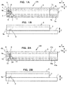
- FIGS. 1A and 1B and FIGS. 2A and 2B illustrate exemplary structures of biosensors according to embodiments.
- FIG. 1A illustrates a top view illustrating an analysis tool (biosensor having four electrodes) according to the embodiment
- FIG. 1B illustrates a side view illustrating the biosensor illustrated in FIG. 1A
- FIG. 2A illustrates a top view illustrating an analysis tool (biosensor having three electrodes) according to the embodiment
- FIG. 2B illustrates a side view illustrating the biosensor illustrated in FIG. 2A .
- the biosensor 10A may be used in the first measuring method.
- the biosensor 10A (hereinafter referred to as “sensor 10A”) has the longitudinal direction (X direction) having one end 10a and the other end 10b and the widthwise direction (Y direction).
- the sensor 10A is formed by stacking and adhering an insulating substrate 1 (hereinafter referred to as "substrate 1"), a spacer 2, and a cover 3 in the height direction (Z direction).
- a synthetic resin is used for the substrate 1.
- the synthetic resin for example, it is possible to use various resins such as polyetherimide (PEI), polyethylene terephthalate (PET), polybutylene terephthalate (PBT), polyethylene (PE), polystyrene (PS), polymethacrylate (PMMA), polypropylene (PP), polyimide resin, acrylic resin, epoxy resin, and glass epoxy.
- PEI polyetherimide
- PET polyethylene terephthalate
- PBT polybutylene terephthalate
- PE polyethylene
- PS polystyrene
- PMMA polymethacrylate
- PP polypropylene
- polyimide resin acrylic resin
- epoxy resin epoxy resin
- glass epoxy glass epoxy
- any insulating material other than the synthetic resin can be used as the substrate 1.
- the insulating material includes, for example, paper, glass, ceramic, and biodegradable material, in addition to the synthetic resin.
- the material, which is the same as that of the substrate 1, can
- An electrode 4, an electrode 5, an electrode 6 and an electrode 7 are provided on the upper surface of the substrate 1 as one example of a plurality of electrodes.
- Each of the electrode 4, the electrode 5, the electrode 6 and the electrode 7 has a key-shape (for example, an L-shape) including a portion which extends in the widthwise direction of the sensor 10A and a portion which extends in the longitudinal direction of the sensor 10A.
- the portion, which extends in the longitudinal direction, is a lead portion 4a, a lead portion 5a, a lead portion 6a and a lead portion 7a.
- the lead portion 4a, the lead portion 5a, the lead portion 6a and the lead portion 7a, which are disposed on the one end 10a side, are not covered with the spacer 2 and the cover 3.
- the lead portion 4a, the lead portion 5a, the lead portion 6a and the lead portion 7a are used for the electric connection with connectors included in a blood glucose meter 20 ( FIG. 3 ) .
- each of the electrodes 4, the electrode 5, the electrode 6 and the electrode 7 is formed by using, for example, a metal material or an alloy thereof such as gold (Au), platinum (Pt), silver (Ag), palladium, ruthenium, and nickel or a carbon material such as carbon.
- a metal material or an alloy thereof such as gold (Au), platinum (Pt), silver (Ag), palladium, ruthenium, and nickel or a carbon material such as carbon.
- each of the electrodes 4, 5, 6 and 7 may be formed as a metal layer having a desired thickness by forming a film of a metal material by means of the physical vapor deposition (PVD, for example, sputtering) or the chemical vapor deposition (CVD).
- PVD physical vapor deposition
- CVD chemical vapor deposition
- each of the electrodes 4, 5, 6 and 7 may be also formed by printing an ink containing a carbon material on the substrate 1 by means of the screen printing.
- the spacer 2 has a cutout portion having a rectangular-shape (recess recessed from the other end 10b toward the one end 10a side) .
- the cutout portion opens toward the other end 10b side.
- a space which has an opening 9a formed by the cutout portion of the spacer 2 is formed on the other end 10b side of the sensor 10A.
- the space is formed by a thickness surface of the cutout portion, an upper surface of the substrate 1 on which the electrodes are provided, and an undersurface (lower surface) of the cover 3.
- the upper surface of the substrate 1 and the undersurface (lower surface) of the cover face each other into the space (not covered by bonding with the spacer 2) .
- the space is used as a passage 9 for the sample.
- An air hole (air vent) 11 is formed through the cover 3.
- the flow passage 9 is formed so that the sample, which is spotted to the opening 9a, is attracted or drawn (introduced) into the flow passage 9 in accordance with the capillary phenomenon and the sample is moved toward the air hole 11 (biological sample flows through the flow passage 9).
- Parts of the electrodes 4, 5, 6, and 7 are exposed in the flow passage 9.
- a reagent 8 is provided (immobilized) on the electrode 6 and the electrode 7. On the other hand, the reagent 8 is not provided on the electrode 4 and the electrode 5.
- the reagent 8 contains an enzyme and/or a substrate.
- the reagent 8 includes a salt (a salt is included, for example, in an enzyme, a substrate, a mediator, and a reagent).
- the reagent 8 may further contain a mediator.
- the enzyme is appropriately selected depending on the type of the sample and the target substance.
- glucose oxidase (GOD) or glucose dehydrogenase (GDH) is applied.
- the mediator is, for example, ferricyanide, ruthenium complex, p-benzoquinone, p-benzoquinone derivative, phenazine methosulfate, methylene blue, ferrocene, ferrocene derivative, and ruthenium complex.
- ferricyanide or ruthenium complex it is preferable to apply ferricyanide or ruthenium complex, and it is more preferable to apply potassium ferricyanide or ruthenium compounds [Ru(NH 3 ) 6 ]cl 3 .
- the electrode 6 and the electrode 7 are used as the electrode pair to be used for the measurement of the glucose value.
- the electrode 6 is used as the working electrode, and the electrode 7 is used as the counter electrode or vice versa.
- the electrode 6 and the electrode 7 are examples of the first electrode and the fourth electrode in the first measuring method.
- the electrode 6 may be used as the counter electrode, and the electrode 7 may be used as the working electrode.
- the reagent is not provided on the electrode (one of the electrode 6 and the electrode 7) which is used as the counter electrode in the measurement of the glucose value.
- the electrode 4 and the electrode 5 are used as the electrode pair to be used for the measurement of Hct value.
- the electrode 4 is used as the working electrode, and the electrode 5 is used as the counter electrode. However, they may be used in an opposite manner.
- the different electrode pairs are used for the measurement of the glucose value and the measurement of the Hct value.
- the electrode pair having no reagent is used for the measurement of the Hct value.
- Neither salt component nor mediator is provided on the electrode 4 and the electrode 5 (counter electrode for the measurement of the Hct value).
- the biosensor 10B illustrated in FIG. 2A and FIG. 2B (hereinafter referred to as "sensor 10B") is used in the second measuring method.
- the sensor 10B has a three-electrode structure which is provided with an electrode 12, an electrode 13, and an electrode 14 in place of the electrode 4, the electrode 5, the electrode 6, and the electrode 7 of the sensor 10A.
- the reagent 8 is fixed or immobilized on the electrode 14. The reagent is not provided on the electrode 12 and the electrode 13, and neither salt component nor mediator is provided thereon.
- the electrode 14 In the measurement of the glucose value, the electrode 14 is used as the working electrode, and the electrode 13 is used as the counter electrode.
- the electrode 12 In the measurement of the Hct value, the electrode 12 is used as the working electrode, and the electrode 13 is used as the counter electrode.
- the electrode 14 corresponds to the first electrode in the second measuring method, and the electrode 12 and the electrode 13 correspond to the second electrode and the third electrode in the second measuring method.
- the electrode 12 may be used as the counter electrode when the glucose value is measured.
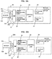
- FIG. 3A illustrates a block diagram illustrating an exemplary arrangement of the blood glucose meter 20 as an example of the measuring apparatus.
- the sensor 10A can be connected to the blood glucose meter 20.
- the blood glucose meter 20 measures the glucose value by using the connected sensor 10A, and the blood glucose meter 20 corrects the glucose value by using the Hct value.
- the blood glucose meter 20 is provided with a first measuring unit 21, a second measuring unit 22, a switch (SW) 31, a control unit 23, a storage unit 24, and an output unit 25.
- the switch 31 is electrically connected to a plurality of connectors (connector 32a, connector 32b, connector 32c, and connector 32d illustrated in FIG. 3A ) .
- the connector 32a is connected to the lead portion 4a (electrode 4) of the sensor 10A, and the connector 32b is connected to the lead portion 5a (electrode 5) of the sensor 10A.
- the connector 32c is connected to the lead portion 6a (electrode 6) of the sensor 10A, and the connector 32d is connected to the lead portion 7a (electrode 7) of the sensor 10A.
- the switch 31 is the switch which changes the states of electric connection and disconnection thereof between the connector 32a, the connector 32b, the connector 32c, and the connector 32d and the electrode 4, the electrode 5, the electrode 6, and the electrode 7.
- the control unit 23 is a processor (for example, Central Processing Unit (CPU)) which executes the program stored in the storage unit 24.
- the storage unit 24 includes a memory which includes a main storage device such as RAM (Random Access Memory) or the like and an auxiliary storage device such as ROM (Read Only Memory), a hard disk or the like.
- the storage unit 24 stores, for example, the program which is to be executed by the control unit 23 and the data which is to be used when the program is executed.
- the output unit 25 includes output devices such as a printer, a display device and the like, and communication devices such as a signal connector, a communication interface and the like.
- the control unit 23 controls the switch 31 during the measurement of the glucose value so that the working electrode (electrode 6) and the counter electrode (electrode 7) for measuring the glucose value are in the states of being electrically connected to the blood glucose meter 20 and the electrode 4 and the electrode 5 are in the disconnected states.
- the first measuring unit 21 is configured by circuit (s) and/or a processor and a memory and performs operations below. That is, the first measuring unit 21, according to an instruction of the control unit 23, starts application of the direct current voltage as the first signal between the electrode 6 and the electrode 7.
- the first measuring unit 21 measures a response current value corresponding to the glucose value (the first electric response value corresponding to the first signal) as a response current value corresponding to the direct current voltage. For example, the first measuring unit 21 measures, as a first electric response value, a response current value at an end point of the given time.
- a time point or timing to obtain the first electric response value may be a given time point other than the end point of the application of the first signal (a given time point in applying of the first signal).
- the control unit 23 controls the switch 31 during the measurement of Hct value so that the working electrode (electrode 4) and the counter electrode (electrode 5) for measuring the Hct value are in the states of being electrically connected to the blood glucose meter 20 and the electrode 6 and the electrode 7 are in the disconnected states.
- the second measuring unit 22 is configured by circuit(s) and/or a processor and a memory and performs operations below. That is, the second measuring unit 22, according to an instruction of the control unit 23, applies the direct current voltage corresponding to the second signal between the electrode 4 and the electrode 5. After the direct current voltage is continuously applied for a given time, the second measuring unit 22 measures, as the second electric response value, a response current value indicating amount of electric charge generated by electrolysis of water in the sample.
- a time point or timing to obtain the second electric response value may be a given time point other than the end point of the application of the second signal (a given time point in applying of the second signal).
- the storage unit 24 stores the calibration curve data for determining the glucose value corresponding to the first electric response value measured by the first measuring unit 21.
- the control unit 23 converts the first electric response value into the glucose value by using the calibration curve data, and thus the control unit 23 calculates the glucose value.
- the glucose value is stored in the storage unit 24 in some cases, and/or the glucose value is outputted (for example, displayed) from the output unit 25 in other cases.
- a calibration curve table may be used to obtain the glucose value instead of the calibration curve data.
- control unit 23 performs a process (Hct correction of the glucose value) in which the glucose value is corrected by using the second electric response value obtained from the second measuring unit 22 or the Hct value obtained from the second electric response value.
- the storage unit 24 stores the calibration curve data or the calibration curve table which represents correlation or corresponding relationship between the second electric response value and the amount of correction.
- the control unit 23 determines the amount of correction corresponding to the second electric response value by using the calibration curve data or the calibration curve table.
- the control unit 23 performs the process for correcting the glucose value, and the control unit 23 calculates the corrected glucose concentration.
- the corrected glucose value is stored in the storage unit 24 in some cases, and/or the corrected glucose value is outputted (for example, displayed) from the output unit 25 in other cases.
- the control unit 23 may correction of the second electric response value based on a temperature of measurement environment of the second electric response value using the calibration curve data or a calibration curve table for the correction.
- FIG. 3B illustrates a blood glucose meter 20A having a structure corresponding to the sensor 10B having the three-electrode structure.
- the connector 32d is omitted, the connector 32a is connected to the lead portion 12a (electrode 12), the connector 32b is connected to the lead portion 13a (electrode 13), and the connector 32c is connected to the lead portion 14a (electrode 14).
- the switch 31 brings about such a state that the first measuring unit 21 is electrically connected to the electrode 14 and the electrode 13, for example, in accordance with the control effected by the control unit 23 during the measurement of the glucose value.
- the switch 31 brings about such a state that the second measuring unit 22 is electrically connected to the electrode 12 and the electrode 13, for example, in accordance with the control effected by the control unit 23 during the measurement of the Hct value. In this way, the switch 31 changes the connection state in relation to the electrodes 12 to 14, the first measuring unit 21, and the second measuring unit 22.
- the first measuring unit 21 applies the direct current voltage as the first signal between the electrode 14 as the working electrode and the electrode 13 as the counter electrode to measure the first electric response value.
- the second measuring unit 22 applies the direct current voltage as the second signal between the electrode 12 as the working electrode and the electrode 13 as the counter electrode to perform the measurement of the second electric response value at the point in time at which the application continues for the given time from the start thereof.
- the blood glucose meter 20A is constructed in the same manner as the blood glucose meter 20.
- FIG. 4 illustrates a flow chart illustrating an exemplary operation of the blood glucose meter 20.
- the spotting of the sample is performed. That is, when the biosensor (for example, sensor 10A) is connected to the blood glucose meter 20, and the opening 9a of the other end 10b of the sensor 10A is brought in contact (subjected to the spotting) with the blood (biological sample) collected from an examinee, then the blood is drawn (attracted) into the flow passage 9 in accordance with the capillary force, and the interior of the flow passage 9 is filled therewith.
- the biosensor for example, sensor 10A
- the control unit 23 applies the voltage to the electrode before the spotting to observe the applied voltage.
- the control unit 23 detects the change of the voltage caused by the contact between the blood and the electrode as a result of the spotting, and the control unit 23 detects that the blood is introduced into the flow passage 9. Then, the control unit 23 starts the measurement of the Hct value (S02) .
- control unit 23 controls the second measuring unit 22 to apply the second signal to the blood. That is, the control unit 23 gives the instruction to the second measuring unit 22 so that the direct current voltage (for example, 2.5 V) corresponding to the second signal is applied to the electrode pair (electrode 4 and electrode 5) for measuring Hct value.
- direct current voltage for example, 2.5 V
- the second measuring unit 22 waits until the application of the direct current voltage corresponding to the second signal continues for the given time (about 2 seconds) after the start thereof, and the second measuring unit 22 measures the second electric response of the blood at the point in time at which the application continues for the given time, namely a response value does not include amount of electric charge based on the reagent and indicates amount of electric charge generated by electrolysis of water in the sample (S03) .
- the second measuring unit 22 measures the response signal depending on the direct current voltage, and the response signal is subjected to the A/D conversion and sent to the control unit 23.
- the control unit 23 When the control unit 23 acquires the second electric response of the blood depending on the second signal, the control unit 23 starts the measurement of glucose. That is, the control unit 23 applies the first signal to the blood (S04) . That is, the control unit 23 instructs the first measuring unit 21 that the direct current voltage as the first signal, which is lower than the second signal, is applied to the electrode pair (electrode 6 and electrode 7) for measuring glucose. The first measuring unit 21 applies the direct current voltage in accordance with the instruction.
- the first measuring unit 21 measures the first electric response of the blood depending on the first signal (S05). For example, the first measuring unit 21 measures the response current of the first signal.
- the second measuring unit 22 performs the A/D conversion of the response current to be sent to the control unit 23.
- the control unit 23 is operated as the correcting unit to perform the correcting process for the glucose value (S06) . That is, the control unit 23 calculates the value of the correction object component contained in the blood (glucose value) by using the value of the first electric response (response current) acquired in S05, the calibration curve data or the calibration curve table. Further, the control unit 23 calculates the corrected glucose value by using the second electric response value acquired in S03 (or the Hct value corresponding to the second electric response).
- the control unit 23 outputs the corrected glucose value (S07) . That is, the control unit 23 stores the glucose value corrected in S06 in the storage unit 24, and the glucose value is displayed on the output unit 25 (display) .
- the control unit 23 can also transmit the glucose value to any other device via any wired or wireless network by using the output unit 25. Note that even when the sensor 10B and the blood glucose meter 20A are applied, the process, which is the same as or equivalent to that illustrated in FIG. 4 , is performed. Therefore, any detailed explanation of the process is omitted. Note that in the exemplary operation illustrated in FIG. 4 , the measurement of the Hct value is performed before the measurement of the glucose value. However, the order of the operation may be reversed.
- Example 1 an explanation will be made about the measurement of the glucose value and the measurement of the Hct value based on the use of a biosensor in which any reagent is not provided on a working electrode and a counter electrode used for the measurement of the Hct value.
- a biosensor having the structure of the sensor 10A was manufactured, in which the electrodes 4 to 7 were made of ruthenium.
- the reagent 8 was provided on the electrode 6 and the electrode 7.
- the formulation and the production method of the reagent 8 are as follows.
- An enzyme solution was prepared, which contained polyvinyl alcohol (PVA 146,000) 0.8% by weight, ruthenium compound [Ru(NH 3 ) 6 ]Cl 3 1.6% by weight, FAD-GDH 2.7 U, 1-methoxy PMS 0.3% by weight, and ACES buffer (pH 6.5). 0.5 ⁇ L of the enzyme solution was dispensed, followed by being dried at 25°C to thereby obtain the reagent 8.
- the evaluation method was carried out in accordance with the following procedure.
- the application of the direct current voltage (2.5 V: corresponding to the second signal having the second value) for measuring Hct value was started 0.5 seconds (0.5 seconds open circuit) after connecting, to the blood glucose meter 20, the electrodes for measuring the Hct value (electrode 4 and electrode 5) of the sensor 10A in which the specimen was introduced into the flow passage.
- the application of the direct current voltage was continued for 2.5 seconds, and the response current (second electric response value) was measured 2.5 seconds after the start of the application (3 seconds after the start of the measurement).
- the application was stopped 2.5 seconds after the start of the application of direct current voltage 2.5 V (second signal), and a state of open circuit (no electric power-applied state) was given for about 7 seconds.
- the change of the electrode pair as the application object for applying the direct current voltage namely, change from the electrode 4 and the electrode 5 to the electrode 6 and the electrode 7) was performed.
- the direct current voltage for measuring the glucose value 200 mV: corresponding to the first signal having the first value
- the response current was measured at the point in time of 14 seconds after the start of the measurement.
- Table 1 illustrates results of the measurement of the second electric response values (response currents) of the respective biological samples in which the glucose value was constant (336 mg/dl) and the Hct value was 0%, 20%, 42%, and 70%.
- the measured value of the second electric response value is the measured value (3 seconds value) obtained at the point in time at which 3 seconds elapse after the start of the measurement as referred to in the measuring method of (2) described above (at the point in time at which the application of the second signal continues for 2.5 seconds).
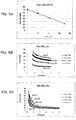
- FIG. 5A illustrates a graph illustrating the linearity of the Hct value (Hct linearity) prepared based on the results of the measurement illustrated in Table 1.
- FIG. 5B illustrates the time-dependent change of the second electric response value measured by using the specimen group 2 (having the constant glucose value).
- FIG. 5C illustrates the time-dependent change of the first electric response value measured by using the specimen group 2 (having the constant glucose value).
- the graph illustrated in FIG. 5A illustrates the correlation (corresponding relationship) between the second electric response value and the Hct value (linearity of the calibration curve of the Hct value) obtained when the glucose value is constant. As illustrated in FIG. 5A , it has been revealed that the correlation between the second electric response value and the Hct value exhibits the linear form, which can be preferably used as the calibration curve.
- the second electric response value which is obtained when about 2 seconds elapse after the start of the measurement, is substantially constant irrelevant to (irrespective of) the difference in the Hct value (in the range of 0 to 70%). It has been revealed that the stable second electric response value can be obtained even when the reagent is not provided for both of the working electrode and the counter electrode.
- the first electric response value exhibits the time-dependent change depending on the Hct value, but the first electric response value is the constant value approximately at the point in time exceeding 13 seconds. Accordingly, it is appreciated that the first electric response value, which becomes the constant value after the elapse of the given time, can be measured even when the measurement of glucose is performed following the measurement of the Hct value.
- FIG. 6A illustrates the time-dependent change of the second electric response value measured by using the specimen group 1 in which the Hct value is constant (42%).
- FIG. 6B illustrates the time-dependent change of the first electric response value measured by using the specimen group 1 in which the Hct value is constant (42%) .
- the time-dependent change of the second electric response value in which the time-dependent change is approximately equivalent, was observed irrelevant to (irrespective of) the difference in the glucose value (in the range of 0 to 800 mg/dl).
- the lower the glucose value is the lower the first electric response value is.
- the first electric response value which was substantially constant approximately after the point in time exceeding 13 seconds, was observed. In this way, it has been revealed that the preferred measurement of glucose is performed even when the glucose value is measured following the measurement of the Hct value.
- the structures and the arrangements explained in the embodiments can be appropriately combined with each other.
Landscapes
- Health & Medical Sciences (AREA)
- Life Sciences & Earth Sciences (AREA)
- Chemical & Material Sciences (AREA)
- Molecular Biology (AREA)
- Physics & Mathematics (AREA)
- Immunology (AREA)
- Hematology (AREA)
- General Physics & Mathematics (AREA)
- Analytical Chemistry (AREA)
- Pathology (AREA)
- General Health & Medical Sciences (AREA)
- Biochemistry (AREA)
- Chemical Kinetics & Catalysis (AREA)
- Electrochemistry (AREA)
- Engineering & Computer Science (AREA)
- Biomedical Technology (AREA)
- Urology & Nephrology (AREA)
- Spectroscopy & Molecular Physics (AREA)
- Medicinal Chemistry (AREA)
- Food Science & Technology (AREA)
- Biotechnology (AREA)
- Cell Biology (AREA)
- Microbiology (AREA)
- Investigating Or Analysing Biological Materials (AREA)
- Apparatus Associated With Microorganisms And Enzymes (AREA)
Applications Claiming Priority (2)
| Application Number | Priority Date | Filing Date | Title |
|---|---|---|---|
| JP2017157662 | 2017-08-17 | ||
| JP2018150637A JP7175129B2 (ja) | 2017-08-17 | 2018-08-09 | 測定方法、及び測定装置 |
Publications (1)
| Publication Number | Publication Date |
|---|---|
| EP3444602A1 true EP3444602A1 (fr) | 2019-02-20 |
Family
ID=63311829
Family Applications (1)
| Application Number | Title | Priority Date | Filing Date |
|---|---|---|---|
| EP18189570.7A Withdrawn EP3444602A1 (fr) | 2017-08-17 | 2018-08-17 | Procédé et dispositif de mesure |
Country Status (3)
| Country | Link |
|---|---|
| US (1) | US20190056346A1 (fr) |
| EP (1) | EP3444602A1 (fr) |
| CN (1) | CN109406591A (fr) |
Cited By (1)
| Publication number | Priority date | Publication date | Assignee | Title |
|---|---|---|---|---|
| US12507924B2 (en) | 2020-06-23 | 2025-12-30 | Roche Diabetes Care, Inc. | Analyte sensor and a method for producing an analyte sensor |
Citations (9)
| Publication number | Priority date | Publication date | Assignee | Title |
|---|---|---|---|---|
| US20030146110A1 (en) * | 2002-02-01 | 2003-08-07 | Karinka Shirdhara Alva | Electrochemical biosensor strip for analysis of liquid samples |
| JP2005147990A (ja) | 2003-11-19 | 2005-06-09 | Matsushita Electric Ind Co Ltd | 基質濃度の測定方法 |
| EP1707953A1 (fr) * | 2003-12-04 | 2006-10-04 | Matsushita Electric Industrial Co., Ltd. | Procede de mesure d'hematocrite (hct), detecteur utilise a cet effet, et instrument de mesure |
| EP2261646A1 (fr) * | 2008-03-27 | 2010-12-15 | Panasonic Corporation | Dispositif de mesure, systeme de mesure et procede de mesure de concentration |
| JP4611208B2 (ja) | 2003-12-04 | 2011-01-12 | パナソニック株式会社 | 血液成分の測定方法およびそれに用いるセンサならびに測定装置 |
| EP2781914A1 (fr) * | 2011-11-18 | 2014-09-24 | Murata Manufacturing Co., Ltd. | Procédé de mesure de niveaux d'hématocrite, procédé d'analyse quantitative utilisant ledit procédé de mesure et puce de capteur |
| EP2799855A1 (fr) * | 2013-05-02 | 2014-11-05 | ARKRAY, Inc. | Appareil et procédé de mesure |
| EP2877092A1 (fr) * | 2012-07-27 | 2015-06-03 | Bayer HealthCare LLC | Système et procédé pour la détection de détecteurs utilisés et secs |
| JP2016510124A (ja) | 2013-03-15 | 2016-04-04 | エフ.ホフマン−ラ ロシュ アーゲーF. Hoffmann−La Roche Aktiengesellschaft | パルスdcブロックを有するテスト・シーケンスで分析物を電気化学的に測定する方法およびデバイス、装置とそれらを組み込むシステム |
Family Cites Families (3)
| Publication number | Priority date | Publication date | Assignee | Title |
|---|---|---|---|---|
| EP3115777B1 (fr) * | 2004-04-19 | 2020-01-08 | PHC Holdings Corporation | Procede de mesure de composants du sang |
| EP2990784B1 (fr) * | 2013-04-26 | 2017-12-20 | Panasonic Healthcare Holdings Co., Ltd. | Procédé de mesure d'échantillon liquide |
| CN107250792A (zh) * | 2014-12-31 | 2017-10-13 | 三伟达保健公司 | 具有干扰校正的葡萄糖测试条 |
-
2018
- 2018-08-16 CN CN201810933854.3A patent/CN109406591A/zh active Pending
- 2018-08-17 EP EP18189570.7A patent/EP3444602A1/fr not_active Withdrawn
- 2018-08-17 US US16/104,516 patent/US20190056346A1/en not_active Abandoned
Patent Citations (10)
| Publication number | Priority date | Publication date | Assignee | Title |
|---|---|---|---|---|
| US20030146110A1 (en) * | 2002-02-01 | 2003-08-07 | Karinka Shirdhara Alva | Electrochemical biosensor strip for analysis of liquid samples |
| JP2005147990A (ja) | 2003-11-19 | 2005-06-09 | Matsushita Electric Ind Co Ltd | 基質濃度の測定方法 |
| EP1707953A1 (fr) * | 2003-12-04 | 2006-10-04 | Matsushita Electric Industrial Co., Ltd. | Procede de mesure d'hematocrite (hct), detecteur utilise a cet effet, et instrument de mesure |
| JP4611208B2 (ja) | 2003-12-04 | 2011-01-12 | パナソニック株式会社 | 血液成分の測定方法およびそれに用いるセンサならびに測定装置 |
| EP2261646A1 (fr) * | 2008-03-27 | 2010-12-15 | Panasonic Corporation | Dispositif de mesure, systeme de mesure et procede de mesure de concentration |
| EP2781914A1 (fr) * | 2011-11-18 | 2014-09-24 | Murata Manufacturing Co., Ltd. | Procédé de mesure de niveaux d'hématocrite, procédé d'analyse quantitative utilisant ledit procédé de mesure et puce de capteur |
| EP2877092A1 (fr) * | 2012-07-27 | 2015-06-03 | Bayer HealthCare LLC | Système et procédé pour la détection de détecteurs utilisés et secs |
| JP2016510124A (ja) | 2013-03-15 | 2016-04-04 | エフ.ホフマン−ラ ロシュ アーゲーF. Hoffmann−La Roche Aktiengesellschaft | パルスdcブロックを有するテスト・シーケンスで分析物を電気化学的に測定する方法およびデバイス、装置とそれらを組み込むシステム |
| EP2799855A1 (fr) * | 2013-05-02 | 2014-11-05 | ARKRAY, Inc. | Appareil et procédé de mesure |
| JP2014232102A (ja) | 2013-05-02 | 2014-12-11 | アークレイ株式会社 | 測定装置、及び測定方法 |
Cited By (2)
| Publication number | Priority date | Publication date | Assignee | Title |
|---|---|---|---|---|
| US12507924B2 (en) | 2020-06-23 | 2025-12-30 | Roche Diabetes Care, Inc. | Analyte sensor and a method for producing an analyte sensor |
| US12507923B2 (en) | 2020-06-23 | 2025-12-30 | Roche Diabetes Care, Inc. | Analyte sensor and a method for producing an analyte sensor |
Also Published As
| Publication number | Publication date |
|---|---|
| CN109406591A (zh) | 2019-03-01 |
| US20190056346A1 (en) | 2019-02-21 |
Similar Documents
| Publication | Publication Date | Title |
|---|---|---|
| US9164054B2 (en) | Method and apparatus for assay of electrochemical properties | |
| US8414759B2 (en) | Analyte determination methods and devices | |
| JP6817111B2 (ja) | 電気化学式バイオセンサを用いた物質の測定方法及び測定装置 | |
| CN106353387A (zh) | 一种电化学测试条及同时检测多种待测物的方法 | |
| RU2546862C2 (ru) | Биосенсорная система и тестовые сенсоры для определения концентрации анализируемого вещества (варианты) | |
| JP2014224828A5 (fr) | ||
| KR101357134B1 (ko) | 전기화학적 바이오센서, 휴대용 계측기 및 이들을 사용한 혈액시료 중 분석대상물질의 농도 측정방법 | |
| JP7175129B2 (ja) | 測定方法、及び測定装置 | |
| EP3444602A1 (fr) | Procédé et dispositif de mesure | |
| EP3454057A1 (fr) | Procédé et appareil de mesure | |
| US10788441B2 (en) | Measuring method of sensor using interdigitated array electrode, measuring apparatus and computer readable medium storing measuring program | |
| JP2019035749A (ja) | 測定方法、及び測定装置 | |
| JP6997659B2 (ja) | 測定方法、及び測定装置 | |
| CA2804931C (fr) | Procede et appareil d'analyse de proprietes electrochimiques | |
| AU2012204094B2 (en) | Method and apparatus for assay of electrochemical properties | |
| AU2013204819A1 (en) | Method and apparatus for assay of electrochemical properties | |
| HK1143861A (zh) | 多区域和电势测试传感器、方法及系统 | |
| HK1099075B (en) | Method and apparatus for assay of electrochemical properties |
Legal Events
| Date | Code | Title | Description |
|---|---|---|---|
| PUAI | Public reference made under article 153(3) epc to a published international application that has entered the european phase |
Free format text: ORIGINAL CODE: 0009012 |
|
| STAA | Information on the status of an ep patent application or granted ep patent |
Free format text: STATUS: THE APPLICATION HAS BEEN PUBLISHED |
|
| AK | Designated contracting states |
Kind code of ref document: A1 Designated state(s): AL AT BE BG CH CY CZ DE DK EE ES FI FR GB GR HR HU IE IS IT LI LT LU LV MC MK MT NL NO PL PT RO RS SE SI SK SM TR |
|
| AX | Request for extension of the european patent |
Extension state: BA ME |
|
| STAA | Information on the status of an ep patent application or granted ep patent |
Free format text: STATUS: REQUEST FOR EXAMINATION WAS MADE |
|
| 17P | Request for examination filed |
Effective date: 20190820 |
|
| RBV | Designated contracting states (corrected) |
Designated state(s): AL AT BE BG CH CY CZ DE DK EE ES FI FR GB GR HR HU IE IS IT LI LT LU LV MC MK MT NL NO PL PT RO RS SE SI SK SM TR |
|
| STAA | Information on the status of an ep patent application or granted ep patent |
Free format text: STATUS: EXAMINATION IS IN PROGRESS |
|
| 17Q | First examination report despatched |
Effective date: 20211021 |
|
| STAA | Information on the status of an ep patent application or granted ep patent |
Free format text: STATUS: THE APPLICATION HAS BEEN WITHDRAWN |
|
| 18W | Application withdrawn |
Effective date: 20220223 |