EP3444632A1 - Dispositif de traitement de signal et appareil du type radar - Google Patents
Dispositif de traitement de signal et appareil du type radar Download PDFInfo
- Publication number
- EP3444632A1 EP3444632A1 EP17782161.8A EP17782161A EP3444632A1 EP 3444632 A1 EP3444632 A1 EP 3444632A1 EP 17782161 A EP17782161 A EP 17782161A EP 3444632 A1 EP3444632 A1 EP 3444632A1
- Authority
- EP
- European Patent Office
- Prior art keywords
- wave
- analysis
- frequency area
- module
- echo
- Prior art date
- Legal status (The legal status is an assumption and is not a legal conclusion. Google has not performed a legal analysis and makes no representation as to the accuracy of the status listed.)
- Granted
Links
Images





Classifications
-
- G—PHYSICS
- G01—MEASURING; TESTING
- G01S—RADIO DIRECTION-FINDING; RADIO NAVIGATION; DETERMINING DISTANCE OR VELOCITY BY USE OF RADIO WAVES; LOCATING OR PRESENCE-DETECTING BY USE OF THE REFLECTION OR RERADIATION OF RADIO WAVES; ANALOGOUS ARRANGEMENTS USING OTHER WAVES
- G01S13/00—Systems using the reflection or reradiation of radio waves, e.g. radar systems; Analogous systems using reflection or reradiation of waves whose nature or wavelength is irrelevant or unspecified
- G01S13/88—Radar or analogous systems specially adapted for specific applications
- G01S13/95—Radar or analogous systems specially adapted for specific applications for meteorological use
- G01S13/956—Radar or analogous systems specially adapted for specific applications for meteorological use mounted on ship or other platform
-
- G—PHYSICS
- G01—MEASURING; TESTING
- G01C—MEASURING DISTANCES, LEVELS OR BEARINGS; SURVEYING; NAVIGATION; GYROSCOPIC INSTRUMENTS; PHOTOGRAMMETRY OR VIDEOGRAMMETRY
- G01C13/00—Surveying specially adapted to open water, e.g. sea, lake, river or canal
-
- G—PHYSICS
- G01—MEASURING; TESTING
- G01S—RADIO DIRECTION-FINDING; RADIO NAVIGATION; DETERMINING DISTANCE OR VELOCITY BY USE OF RADIO WAVES; LOCATING OR PRESENCE-DETECTING BY USE OF THE REFLECTION OR RERADIATION OF RADIO WAVES; ANALOGOUS ARRANGEMENTS USING OTHER WAVES
- G01S13/00—Systems using the reflection or reradiation of radio waves, e.g. radar systems; Analogous systems using reflection or reradiation of waves whose nature or wavelength is irrelevant or unspecified
- G01S13/88—Radar or analogous systems specially adapted for specific applications
- G01S13/95—Radar or analogous systems specially adapted for specific applications for meteorological use
-
- G—PHYSICS
- G01—MEASURING; TESTING
- G01S—RADIO DIRECTION-FINDING; RADIO NAVIGATION; DETERMINING DISTANCE OR VELOCITY BY USE OF RADIO WAVES; LOCATING OR PRESENCE-DETECTING BY USE OF THE REFLECTION OR RERADIATION OF RADIO WAVES; ANALOGOUS ARRANGEMENTS USING OTHER WAVES
- G01S7/00—Details of systems according to groups G01S13/00, G01S15/00, G01S17/00
- G01S7/02—Details of systems according to groups G01S13/00, G01S15/00, G01S17/00 of systems according to group G01S13/00
- G01S7/28—Details of pulse systems
- G01S7/285—Receivers
- G01S7/292—Extracting wanted echo-signals
- G01S7/2923—Extracting wanted echo-signals based on data belonging to a number of consecutive radar periods
- G01S7/2926—Extracting wanted echo-signals based on data belonging to a number of consecutive radar periods by integration
-
- G—PHYSICS
- G01—MEASURING; TESTING
- G01S—RADIO DIRECTION-FINDING; RADIO NAVIGATION; DETERMINING DISTANCE OR VELOCITY BY USE OF RADIO WAVES; LOCATING OR PRESENCE-DETECTING BY USE OF THE REFLECTION OR RERADIATION OF RADIO WAVES; ANALOGOUS ARRANGEMENTS USING OTHER WAVES
- G01S7/00—Details of systems according to groups G01S13/00, G01S15/00, G01S17/00
- G01S7/02—Details of systems according to groups G01S13/00, G01S15/00, G01S17/00 of systems according to group G01S13/00
- G01S7/28—Details of pulse systems
- G01S7/285—Receivers
- G01S7/295—Means for transforming co-ordinates or for evaluating data, e.g. using computers
-
- G—PHYSICS
- G01—MEASURING; TESTING
- G01S—RADIO DIRECTION-FINDING; RADIO NAVIGATION; DETERMINING DISTANCE OR VELOCITY BY USE OF RADIO WAVES; LOCATING OR PRESENCE-DETECTING BY USE OF THE REFLECTION OR RERADIATION OF RADIO WAVES; ANALOGOUS ARRANGEMENTS USING OTHER WAVES
- G01S7/00—Details of systems according to groups G01S13/00, G01S15/00, G01S17/00
- G01S7/02—Details of systems according to groups G01S13/00, G01S15/00, G01S17/00 of systems according to group G01S13/00
- G01S7/41—Details of systems according to groups G01S13/00, G01S15/00, G01S17/00 of systems according to group G01S13/00 using analysis of echo signal for target characterisation; Target signature; Target cross-section
-
- G—PHYSICS
- G01—MEASURING; TESTING
- G01S—RADIO DIRECTION-FINDING; RADIO NAVIGATION; DETERMINING DISTANCE OR VELOCITY BY USE OF RADIO WAVES; LOCATING OR PRESENCE-DETECTING BY USE OF THE REFLECTION OR RERADIATION OF RADIO WAVES; ANALOGOUS ARRANGEMENTS USING OTHER WAVES
- G01S7/00—Details of systems according to groups G01S13/00, G01S15/00, G01S17/00
- G01S7/02—Details of systems according to groups G01S13/00, G01S15/00, G01S17/00 of systems according to group G01S13/00
- G01S7/41—Details of systems according to groups G01S13/00, G01S15/00, G01S17/00 of systems according to group G01S13/00 using analysis of echo signal for target characterisation; Target signature; Target cross-section
- G01S7/414—Discriminating targets with respect to background clutter
-
- G—PHYSICS
- G01—MEASURING; TESTING
- G01S—RADIO DIRECTION-FINDING; RADIO NAVIGATION; DETERMINING DISTANCE OR VELOCITY BY USE OF RADIO WAVES; LOCATING OR PRESENCE-DETECTING BY USE OF THE REFLECTION OR RERADIATION OF RADIO WAVES; ANALOGOUS ARRANGEMENTS USING OTHER WAVES
- G01S7/00—Details of systems according to groups G01S13/00, G01S15/00, G01S17/00
- G01S7/02—Details of systems according to groups G01S13/00, G01S15/00, G01S17/00 of systems according to group G01S13/00
- G01S7/41—Details of systems according to groups G01S13/00, G01S15/00, G01S17/00 of systems according to group G01S13/00 using analysis of echo signal for target characterisation; Target signature; Target cross-section
- G01S7/411—Identification of targets based on measurements of radar reflectivity
-
- G—PHYSICS
- G01—MEASURING; TESTING
- G01S—RADIO DIRECTION-FINDING; RADIO NAVIGATION; DETERMINING DISTANCE OR VELOCITY BY USE OF RADIO WAVES; LOCATING OR PRESENCE-DETECTING BY USE OF THE REFLECTION OR RERADIATION OF RADIO WAVES; ANALOGOUS ARRANGEMENTS USING OTHER WAVES
- G01S7/00—Details of systems according to groups G01S13/00, G01S15/00, G01S17/00
- G01S7/02—Details of systems according to groups G01S13/00, G01S15/00, G01S17/00 of systems according to group G01S13/00
- G01S7/41—Details of systems according to groups G01S13/00, G01S15/00, G01S17/00 of systems according to group G01S13/00 using analysis of echo signal for target characterisation; Target signature; Target cross-section
- G01S7/415—Identification of targets based on measurements of movement associated with the target
-
- Y—GENERAL TAGGING OF NEW TECHNOLOGICAL DEVELOPMENTS; GENERAL TAGGING OF CROSS-SECTIONAL TECHNOLOGIES SPANNING OVER SEVERAL SECTIONS OF THE IPC; TECHNICAL SUBJECTS COVERED BY FORMER USPC CROSS-REFERENCE ART COLLECTIONS [XRACs] AND DIGESTS
- Y02—TECHNOLOGIES OR APPLICATIONS FOR MITIGATION OR ADAPTATION AGAINST CLIMATE CHANGE
- Y02A—TECHNOLOGIES FOR ADAPTATION TO CLIMATE CHANGE
- Y02A90/00—Technologies having an indirect contribution to adaptation to climate change
- Y02A90/10—Information and communication technologies [ICT] supporting adaptation to climate change, e.g. for weather forecasting or climate simulation
Definitions
- the present disclosure relates to a signal processing device which calculates wave information, including wave height, by processing an echo from a wave, and a radar apparatus provided with the signal processing device.
- wave observation radars as disclosed in Patent Document 1 are known.
- radar apparatus with reference to Fig. 2 of Patent Document 1, echo signals acquired from echoes from a given range on the sea are two-dimensionally fast Fourier transformed (FFT), and with reference to Fig. 3 of Patent Document 1, a two-dimensional Fourier transformed signal Sf is derived. Then, the radar apparatus calculates wave information (a wave direction, a wavelength, etc.) based on the two-dimensional Fourier transformed signal Sf.
- FFT two-dimensionally fast Fourier transformed
- the wave information may not be calculated accurately.
- the present disclosure is to solve the problem, and one purpose thereof is to calculate the wave information accurately.
- the wave information is accurately calculated.
- a signal processor as a signal processing device according to the present disclosure and a radar apparatus provided with the signal processor is described with reference to the drawings.
- the present disclosure may be widely applicable to signal processing devices which acquire wave information, and radar apparatuses provided with the signal processing device.
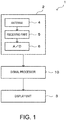
- Fig. 1 is a block diagram of a radar apparatus 1 according to one embodiment of the present disclosure.
- the radar apparatus 1 may calculate wave information (specifically, a wave height, a wavelength, etc.) which is information related to a wave, based on an echo obtained by a transmission wave transmitted being reflected on the wave and coming back.
- the radar apparatus 1 may be configured to be capable of detecting ships which exist within a detection area.
- the radar apparatus 1 of this embodiment may be provided to, for example, a ship (hereinafter, referred to as "the ship" to be distinguished from other ships), such as a fishing boat.
- the radar apparatus 1 may include an antenna unit 2, a signal processor 10, and a display unit 3.
- the antenna unit 2 may include an antenna 4 which functions as both transmitter and receiver, a receiving part 5, and an A/D converter 6.
- the antenna 4 may be a radar antenna which is capable of transmitting a pulse-shaped radio wave as a transmission wave with a strong directivity. Moreover, the antenna 4 may be configured to receive a reflection wave from a target object (in this embodiment, the wave or another ship). The radar apparatus 1 may measure a period of time after a transmission of the pulse-shaped radio wave to a reception of the reflection wave. Thus, the radar apparatus 1 may be capable of detecting a distance r to the target object.
- the antenna 4 may be configured to be capable of rotating 360° in a horizontal plane. The antenna 4 may be configured to repeat the transmission and reception of the radio wave, while changing the transmitting direction of the pulse-shaped radio wave (e.g., changing an antenna angle). With the above configuration, the radar apparatus 1 may be capable of detecting the target object in the plane around the ship over 360°.
- operation after the transmission of the pulse-shaped radio wave until a transmission of a subsequent pulse-shaped radio wave may be referred to as a "sweep.”
- operation of a 360° rotation of the antenna while transmitting and receiving the radio wave may be referred to as a "scan.”
- the receiving part 5 may detect and amplify the echo signal acquired from the echo received by the antenna 4.
- the receiving part 5 may output the amplified echo signal to the A/D converter 6.
- the A/D converter 6 may sample the echo signal of an analog format, and convert it into digital data comprised of multiple bits. This digital data may be echo data.
- the echo data may include data to identify an intensity of the echo signal acquired from the reflection wave received by the antenna 4.
- the A/D converter 6 may output the echo data to the signal processor 10.
- Fig. 2 is a block diagram of the signal processor 10 illustrated in Fig. 1 .
- the signal processor 10 may include an other-ships detecting module 11 (unnecessary target object detecting module), a frequency area spectrum generating module 8, an integrating module 17, and a wave information calculating module 18.
- the signal processor 10 may be comprised of devices, such as a hardware processor 7 (e.g., a CPU, an FPGA, etc.), and a nonvolatile memory.
- a hardware processor 7 e.g., a CPU, an FPGA, etc.
- the CPU may read and execute a program from the nonvolatile memory to function the signal processor 10 as the other-ships detecting module 11, the frequency area spectrum generating module 8, the integrating module 17, and the wave information calculating module 18.
- the other-ships detecting module 11 may extract echo images resulting from other ships (unnecessary target objects). For example, the other-ships detecting module 11 may group, among sampling points having the echo intensity greater than a given threshold, sampling points of which a mutual distance is below a given distance because they are able to be considered as echoes from the same ship. Then, the other-ships detecting module 11 may detect an echo image comprised of a plurality of grouped sampling points, as an echo image from the same ship.
- Fig. 3 is a view illustrating positions etc. of analysis areas Z1-Z5 where classified-by-analysis-area echo data is extracted, the classified-by-analysis-area echo data being extracted by a classified-by-analysis-area data extracting module 12 provided to the frequency area spectrum generating module 8.
- the frequency area spectrum generating module 8 may carry out a frequency analysis of the echoes obtained from waves included in each range of the plurality of analysis areas Z1-Z5 and generate a directional frequency spectrum (frequency area spectrum) for each of the plurality of analysis areas Z1-Z5.
- the analysis areas Z1-Z5 may have the same shape and size. Moreover, the analysis areas Z1-Z5 may be disposed at the same distance with respect to the ship S. Moreover, the analysis areas Z1-Z5 may be provided as areas surrounded by straight lines parallel and perpendicular to a straight line which connects the ship S and a central point of each analysis area. By setting the analysis areas Z1-Z5 as described above, the positions and shape of the analysis areas Z1-Z5 when seen from the ship may be unified.
- the frequency area spectrum generating module 8 may include the classified-by-analysis-area data extracting module 12, a frequency analysis module 13, the wave component extracting module 14, a ⁇ converting module 15, and a directional frequency spectrum converting module 16.
- the classified-by-analysis-area data extracting module 12 may extract the classified-by-analysis-area echo data included in the analysis areas Z1-Z5.
- the number, the positions, and size of the analysis areas Z1-Z5 may be determined beforehand.
- the five analysis areas Z1-Z5 may be disposed at the positions with the same distance with respect to the ship S. For example, with reference to Fig.
- the analysis area Z1 may be disposed in the bow direction of the ship S
- the analysis area Z2 may be disposed in the 60° direction to the right with respect to the bow direction of the ship S
- the analysis area Z3 may be disposed in the 120° direction to the right with respect to the bow direction of the ship S
- the analysis area Z4 may be disposed in the 120° direction to the left with respect to the bow direction of the ship S
- the analysis area Z5 may be disposed in the 60° direction to the left with respect to the bow direction of the ship S.
- Fig. 3 illustrates one example in which comparatively high waves moving in the incoming direction toward the ship S or the outgoing direction from the ship S exist in the analysis areas Z2 and Z5. In Fig. 3 , these waves are indicated as apparent wave crest lines w. Note that, although comparatively low waves also exist in areas other than the analysis areas Z2and Z5 in Fig. 3 , illustration of these waves are omitted. Fig. 3 also illustrates one example in which other ships S1 and S2 exist in the analysis areas Z3 and Z4.
- the classified-by-analysis-area data extracting module 12 may extract for every scan the classified-by-analysis-area echo data as the echo data included in the plurality of analysis areas Z1-Z5 included in an echo image P in a detection area Z0 obtained by one scan.
- the classified-by-analysis-area data extracting module 12 may extract the classified-by-analysis-area echo data for a plurality of scans (e.g., 32 scans) for each of the analysis areas Z1-Z5.
- the number, positions and size of the analysis areas Z1-Z5 illustrated in Fig. 3 may be merely examples, and the number, positions, and size of the analysis areas are not limited to the number, positions, and size illustrated in Fig. 3 , and may be other numbers, positions, and sizes.
- the frequency analysis module 13 may carry out the frequency analysis of the 32 sheets of the classified-by-analysis-area echo data for the analysis areas Z1-Z5.
- the frequency analysis module 13 may perform a three-dimensional Fast Fourier Transform (3D FFT) processing using the 32 sheets of classified-by-analysis-area echo data for each of the analysis areas Z1-Z5.
- 3D FFT three-dimensional Fast Fourier Transform
- the 3D data may be generated for every analysis area, where the units of x-axis and y-axis are rad/m, and the unit of z-axis is rad/sec.
- the x-axis in the 3D data may be a wave number kx in the east-west directions
- the y-axis may be a wave number ky in the north-south directions
- the z-axis may be an angular frequency ⁇ .
- the frequency analysis module 13 may generate the 3D data for each of the analysis areas Z1-Z5.
- Formula (2) may be used when the water depth is deep enough, particularly when the water depth is greater than a half-wavelength, and Formula (1) may be used when Formula (2) is not used.
- the ⁇ converting module 15 may convert the spectrums of the wave components extracted by the wave component extracting module 14 into rectangular coordinates ( ⁇ coordinates) where the x-axis corresponds to a wave direction ⁇ with respect to the ship S and the y-axis corresponds to the angular frequency ⁇ , to generate ⁇ spectrums.
- the ⁇ converting module 15 may generate the ⁇ spectrum for each of the analysis areas Z1-Z5.
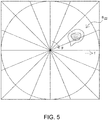
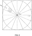
- Figs. 4 to 6 are views illustrating the directional frequency spectrums generated by the directional frequency spectrum converting module 16.
- Fig. 4 is a view illustrating the directional frequency spectrum obtained from the analysis area Z1
- Fig. 5 is a view illustrating the directional frequency spectrum obtained from the analysis area Z2
- Fig. 6 is a view illustrating the directional frequency spectrum obtained from the analysis area Z5.
- the directional frequency spectrums S Zn are spectrums obtained by performing a coordinate conversion of the positions of the respective sampling points which constitute the ⁇ spectrums generated by the ⁇ converting module 15 at polar coordinates where the ship provided with the radar apparatus 1 is used as the origin, the circumferential directions correspond to the direction ⁇ of the wave with respect to the ship S, and the radial direction corresponds to a frequency f of the wave.
- the directional frequency spectrums S Zn may have the echo intensity (corresponding to the height of the wave) at each sampling point which constitutes each location of the polar coordinates, as information. Note that in Figs. 4 to 6 , the echo intensity at each sampling point is illustrated corresponding to the density of hatching comprised of dots. That is, the echo intensities at the sampling points which constitute the dense part of the dot hatching may be higher than the echo intensities at the sampling points which constitute the thin part of the dot hatching.
- Fig. 7 is a view illustrating an integrated directional frequency spectrum S total generated by the integrating module 17.
- the integrating module 17 may integrate the directional frequency spectrums S Zn generated by the directional frequency spectrum converting module 16, and calculate the integrated directional frequency spectrum S total (i, j). For example, the integrating module 17 calculates the integrated directional frequency spectrum S total (i, j) by using the following Formula (3).
- S total represents the integrated directional frequency spectrum, where S total (i, j) is a spectral power (echo intensity) in an arbitrary direction i (0° to 360° with respect to the ship) and at an arbitrary frequency j.
- the directional frequency spectrums S Zn may be integrated where their directions are unified.
- weight coefficients ⁇ Zn may be added to the spectral powers at the same frequency which are obtained from the same direction in the directional frequency spectrums S Zn , and they may be then summed up to be integrated.
- ⁇ Zn may be the weight coefficients set corresponding to the analysis areas Z1-Z5, and a method of setting ⁇ Zn is described below.
- a calculation of the integrated spectrum S total (i, j) may be performed as follows.
- the directional frequency spectrum S Z3 (i, j) obtained from the analysis area Z3 (see Fig. 3 ) where another ship is detected 0 may be used as the weight coefficient ⁇ Z3 .
- the directional frequency spectrum S Z4 (i, j) obtained from the analysis area Z4 where another ship is detected 0 may be used as the weight coefficient ⁇ Z4 .
- the directional frequency spectrums S Zn (i, j) obtained from the analysis areas Z1, Z2 and Z5 where other ships are not detected 1 may be used as the weight coefficients ⁇ Zn . That is, the directional frequency spectrums S Z3 (i, j) and S Z4 (i, j) included in the analysis areas where other ships are detected may be excluded from the candidates for the integration of the integrated directional frequency spectrum S total (i, j).
- the wave information calculating module 18 may calculate the wave information, such as the wave height and the wavelength of the wave, based on the integrated directional frequency spectrum S total calculated by the integrating module 17. For example, the wave height and the wavelength of the wave at a selected location, which is selected by a user using an external device, in the integrated directional frequency spectrum S total may be calculated. The wave height may be calculated based on the echo intensity at the selected location. The wavelength may be calculated based on the frequency f at the selected location. These values calculated by the wave information calculating module 18 may be notified to the display unit 3. The display unit 3 may display these values.
- the accurate wave information cannot be acquired from the analysis area Z3 where another ship S1 is included, and the analysis area Z4 where another ship S2 is included.
- the signal processor 10 of the radar apparatus 1 with reference to Figs. 3 and 7 , only the directional frequency spectrums S Zn obtained from the analysis areas Z1, Z2 and Z5, among the plurality of analysis areas Z1-Z5 other than the analysis areas Z3 and Z4 where other ships are included, may be integrated. Thus, the wave information may be accurately calculated.
- the spectral powers (echo intensities) of the directional frequency spectrums S Zn generated corresponding to the analysis areas Z1-Z5 may be integrated where their directions are unified, as shown in Formula (3). Then, in the radar apparatus 1, the wave information, such as the wave height and the wavelength, may be calculated based on the integrated directional frequency spectrum S total integrated as described above.
- the wave information may be calculated based on the integrated directional frequency spectrum S total obtained by integrating the directional frequency spectrums S Zn generated for the plurality of analysis areas Z1-Z5 as described above.
- the wave information may be calculated based on the integrated directional frequency spectrum S total obtained by integrating the directional frequency spectrums S Zn generated for the plurality of analysis areas Z1-Z5 as described above.
- the radar apparatus 1 it may be possible to reduce the influences by the directional frequency spectrums S Z3 and S Z4 from the analysis areas Z3 and Z4 which are low in the reliability when calculating the wave information.
- the wave information may be accurately calculated.
- the directional frequency spectrums S Zn obtained by multiplying the plurality of directional frequency spectrums S Zn by the respective weight coefficients ⁇ Zn determined corresponding to the plurality of directional frequency spectrums S Zn may be integrated to generate the integrated directional frequency spectrum S total (i, j).
- the wave information since it becomes possible to set the values of the weight coefficients ⁇ Zn according to the reliability of the directional frequency spectrums S Zn when calculating the wave information, the wave information may be calculated more accurately.
- the values of the weight coefficients ⁇ Zn may be determined according to the unnecessary target objects which give adverse influences when calculating the accurate wave information to appropriately set the values of the weight coefficients ⁇ Zn .
- the values of the weight coefficients ⁇ Z3 and ⁇ Z4 of the directional frequency spectrums S Z3 and S Z4 obtained from the analysis areas Z3 and Z4 where the unnecessary target objects are detected may be set to zero to significantly reduce the adverse influences which the unnecessary target objects when calculating the wave information give to the wave information.
- the values of the weight coefficients ⁇ Zn of the directional frequency spectrums S Z3 and S Z4 obtained from the analysis areas Z3 and Z4 where other ships are detected is set to zero to prevent that the echoes of other ships or the echoes resulting from the wakes of other ships give influences to the wave information.
- the signal processor 10 since the directional frequency spectrums are generated based on the wave components extracted by the wave component extracting module 14, the echoes resulting from the unnecessary target objects may become difficult to be reflected in the wave information. Thus, the wave information may be calculated more accurately.
- the radar apparatus provided with the signal processor 10 which is capable of calculating the wave information accurately may be configured.
- the echoes from other ships as the unnecessary target objects may be received using the antenna 4 which receives the echoes from the waves, and other ships may be detected based on the echoes. That is, according to the radar apparatus 1, since other ships are detectable using the antenna 4 provided to the radar apparatus 1 for calculating the wave information, it may become unnecessary to provide other special equipment in order to detect other ships. Therefore, according to the radar apparatus 1, the configuration of the apparatus may be simplified.
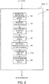
- the signal processor 10a of this modification may have a land detecting module 20 and a waterfall detecting module 21 as the unnecessary target object detecting modules, other than the components which the signal processor 10 of the above embodiment has.
- the land detecting module 20 may detect land included in a detection area. For example, the land detecting module 20 may compare the position of the land included in a nautical chart stored in the radar apparatus 1 according to this modification with the position of the echo obtained by the radar apparatus 1 to determine whether the echo is an echo from the land.
- the waterfall detecting module 21 may detect an area where rain or snow falls within the detection area. An echo from the rain or snow may have a more gradual inclination of the rising part and the falling part than those of ships and land. The waterfall detecting module 21 may determine whether the echo is an echo from the rain or snow based on such a feature of the rain or snow, i.e., based on the degree of the inclination of the rising part and the falling part described above.
- the integrating module 17 may calculate the integrated directional frequency spectrum S total by using Formula (3), substantially similar to the above embodiment. Note that, unlike the above embodiment, the integrating module 17 may use 0 as the weight coefficients ⁇ Zn of the spectral powers at locations included in the analysis areas where the land and the rain or snow are detected. That is, the integrating module 17 may also exclude the spectral powers at the locations included in the analysis areas where the land and the rain or snow are detected, from the candidates for the integration of the integrated directional frequency spectrum.
- the directional frequency spectrums obtained from the analysis areas where the land or the rain or snow is detected may be also excluded from the candidates for the integration of the integrated directional frequency spectrum, as well as the directional frequency spectrums obtained from the analysis areas where other ships are detected.
- the wave information may be calculated more accurately, compared with the case where only the directional frequency spectrums obtained from the analysis areas where other ships are detected is excluded from the candidates for the integration of the integrated directional frequency spectrum.
Landscapes
- Engineering & Computer Science (AREA)
- Radar, Positioning & Navigation (AREA)
- Remote Sensing (AREA)
- Physics & Mathematics (AREA)
- General Physics & Mathematics (AREA)
- Computer Networks & Wireless Communication (AREA)
- Electromagnetism (AREA)
- Ocean & Marine Engineering (AREA)
- Life Sciences & Earth Sciences (AREA)
- Hydrology & Water Resources (AREA)
- Radar Systems Or Details Thereof (AREA)
Applications Claiming Priority (2)
| Application Number | Priority Date | Filing Date | Title |
|---|---|---|---|
| JP2016079172 | 2016-04-11 | ||
| PCT/JP2017/009495 WO2017179343A1 (fr) | 2016-04-11 | 2017-03-09 | Dispositif de traitement de signal et appareil du type radar |
Publications (3)
| Publication Number | Publication Date |
|---|---|
| EP3444632A1 true EP3444632A1 (fr) | 2019-02-20 |
| EP3444632A4 EP3444632A4 (fr) | 2019-12-04 |
| EP3444632B1 EP3444632B1 (fr) | 2024-10-09 |
Family
ID=60042570
Family Applications (1)
| Application Number | Title | Priority Date | Filing Date |
|---|---|---|---|
| EP17782161.8A Active EP3444632B1 (fr) | 2016-04-11 | 2017-03-09 | Dispositif de traitement de signal et appareil du type radar |
Country Status (5)
| Country | Link |
|---|---|
| US (1) | US11249185B2 (fr) |
| EP (1) | EP3444632B1 (fr) |
| JP (1) | JP6712313B2 (fr) |
| CN (1) | CN108885257A (fr) |
| WO (1) | WO2017179343A1 (fr) |
Families Citing this family (5)
| Publication number | Priority date | Publication date | Assignee | Title |
|---|---|---|---|---|
| JP2020008535A (ja) * | 2018-07-12 | 2020-01-16 | 日本無線株式会社 | 目標検出装置及び目標検出プログラム |
| EP3719536A1 (fr) * | 2019-04-01 | 2020-10-07 | Siemens Gamesa Renewable Energy A/S | Éolienne comportant une détermination des caractéristiques des vagues au niveau de la mer |
| US11448721B2 (en) * | 2019-06-25 | 2022-09-20 | Infineon Technologies Ag | In device interference mitigation using sensor fusion |
| US11852745B2 (en) * | 2021-09-23 | 2023-12-26 | Rockwell Collins, Inc. | System and method to select and display prioritized azimuth slice vertical radar image |
| KR102558955B1 (ko) * | 2023-04-21 | 2023-07-21 | 한국해양과학기술원 | 레이더 영상처리를 이용한 수심측정 시스템 및 방법 |
Family Cites Families (27)
| Publication number | Priority date | Publication date | Assignee | Title |
|---|---|---|---|---|
| JP2597027B2 (ja) | 1990-03-13 | 1997-04-02 | 防衛庁技術研究本部長 | 波浪観測レーダ |
| WO1992021041A1 (fr) * | 1991-05-16 | 1992-11-26 | The Commonwealth Of Australia | Donnees meterologiques et oceanographiques |
| US5594451A (en) * | 1995-06-06 | 1997-01-14 | Hughes Aircraft Company | Processing method using an advanced radar waveform for simultaneous matched processing and range profiling of different size targets |
| JP3730486B2 (ja) * | 2000-07-14 | 2006-01-05 | 株式会社東芝 | 気象レーダ |
| US6862537B2 (en) * | 2002-03-21 | 2005-03-01 | Ford Global Technologies Llc | Sensor fusion system architecture |
| JP3783058B2 (ja) * | 2003-07-19 | 2006-06-07 | 独立行政法人情報通信研究機構 | レーダ画像からの波浪方向スペクトル逆推定方法及びシステム |
| JP5336292B2 (ja) * | 2009-08-04 | 2013-11-06 | 日本無線株式会社 | レーダ波浪解析装置 |
| US8305257B2 (en) * | 2009-09-02 | 2012-11-06 | Trizna Dennis B | Method and apparatus for coherent marine radar measurements of properties of ocean waves and currents |
| CN101813476B (zh) * | 2010-03-19 | 2011-08-31 | 天津大学 | 近海波浪参数立体实时监测系统 |
| CN102073037B (zh) * | 2011-01-05 | 2012-07-11 | 哈尔滨工程大学 | 基于自适应阈值选取技术的迭代海流反演方法 |
| US9385766B2 (en) * | 2012-03-01 | 2016-07-05 | Nec Corporation | Digital signal processing device, receiving device, and signal transmitting and receiving system |
| CN102621531B (zh) * | 2012-04-12 | 2014-05-07 | 哈尔滨工程大学 | 一种基于x波段雷达图像的降雨干扰抑制方法 |
| JP6226516B2 (ja) * | 2012-09-05 | 2017-11-15 | 古野電気株式会社 | ドップラ処理装置、レーダ装置、ドップラ処理方法及びドップラ処理プログラム |
| CN102944871A (zh) * | 2012-11-09 | 2013-02-27 | 中国海洋大学 | 一种提取雷达图像中海浪参数的方法 |
| JP6104010B2 (ja) | 2013-03-26 | 2017-03-29 | キヤノン株式会社 | 画像処理装置、撮像装置、画像処理方法、画像処理プログラム、および、記憶媒体 |
| US9746554B2 (en) * | 2013-04-09 | 2017-08-29 | Valeo Radar Systems, Inc. | Radar imaging system and related techniques |
| EP3006956B1 (fr) * | 2013-05-31 | 2019-08-14 | Furuno Electric Co., Ltd. | Dispositif, procédé et programme d'estimation de courant de marée de surface et dispositif radar |
| JP2014235049A (ja) * | 2013-05-31 | 2014-12-15 | 古野電気株式会社 | 波頭速度分布推定装置、波頭速度分布推定方法、及び波頭速度分布推定プログラム |
| CN103293521B (zh) * | 2013-06-26 | 2015-03-25 | 武汉大学 | 一种利用x波段雷达探测近海海域水深的方法 |
| JP6154219B2 (ja) * | 2013-07-03 | 2017-06-28 | 古野電気株式会社 | エコー信号処理装置、波浪レーダ装置、エコー信号処理方法、及びエコー信号処理プログラム |
| CN103558600A (zh) * | 2013-11-15 | 2014-02-05 | 武汉大学 | 一种利用s波段雷达探测海表面风场的方法 |
| JP6415288B2 (ja) * | 2014-03-03 | 2018-10-31 | 三菱電機株式会社 | レーダ装置 |
| CN103969643B (zh) * | 2014-05-09 | 2016-09-14 | 哈尔滨工程大学 | 一种基于新型海浪色散关系带通滤波器进行x波段导航雷达反演海浪参数方法 |
| US9841497B2 (en) * | 2014-06-05 | 2017-12-12 | Infineon Technologies Ag | Method, device and system for processing radar signals |
| US10520584B2 (en) * | 2014-06-05 | 2019-12-31 | Continental Automotive Systems, Inc. | Radar system with optimized storage of temporary data |
| DE102014110667A1 (de) * | 2014-07-29 | 2016-02-04 | Valeo Schalter Und Sensoren Gmbh | Vefahren zum Klassifizieren eines Objektes in einem Umgebungsbereich eines Kraftfahrzeugs, Fahrerassistenzsystem und Kraftfahrzeug |
| US9557407B1 (en) * | 2015-08-21 | 2017-01-31 | Qualcomm Incorporated | Radar detection for adjacent segments in wireless communications |
-
2017
- 2017-03-09 CN CN201780022773.1A patent/CN108885257A/zh active Pending
- 2017-03-09 EP EP17782161.8A patent/EP3444632B1/fr active Active
- 2017-03-09 JP JP2018511929A patent/JP6712313B2/ja active Active
- 2017-03-09 WO PCT/JP2017/009495 patent/WO2017179343A1/fr not_active Ceased
-
2018
- 2018-10-11 US US16/157,468 patent/US11249185B2/en active Active
Also Published As
| Publication number | Publication date |
|---|---|
| JPWO2017179343A1 (ja) | 2019-02-14 |
| US20190072670A1 (en) | 2019-03-07 |
| CN108885257A (zh) | 2018-11-23 |
| EP3444632B1 (fr) | 2024-10-09 |
| JP6712313B2 (ja) | 2020-06-17 |
| WO2017179343A1 (fr) | 2017-10-19 |
| EP3444632A4 (fr) | 2019-12-04 |
| US11249185B2 (en) | 2022-02-15 |
Similar Documents
| Publication | Publication Date | Title |
|---|---|---|
| US11249185B2 (en) | Signal processing device and radar apparatus | |
| CN110907907B (zh) | 一种海杂波多普勒谱特性分析对比方法 | |
| EP3012656B1 (fr) | Dispositif d'élimination du fouillis et appareil radar comprenant ce dispositif | |
| Lund et al. | Marine radar ocean wave retrieval’s dependency on range and azimuth | |
| US8704706B2 (en) | Radar return signal processing apparatus and method | |
| US20050179579A1 (en) | Radar receiver motion compensation system and method | |
| US20180164406A1 (en) | Probabilistic signal, detection, and track processing architecture and system | |
| JP6192151B2 (ja) | 信号選別装置、信号選別方法、及びレーダ装置。 | |
| EP3196669B1 (fr) | Appareil radar et procédé de suivi d'objet cible | |
| CN111487621A (zh) | 一种基于雷达图像的海表流场反演方法及电子设备 | |
| EP3746808B1 (fr) | Traitement d'image radar | |
| Horstmann et al. | Wind, wave, and current retrieval utilizing X-band marine radars | |
| Gangeskar | Verifying high-accuracy ocean surface current measurements by X-band radar for fixed and moving installations | |
| Ries et al. | Geometry-induced range-dependence compensation for bistatic STAP with conformal arrays | |
| JPH03262990A (ja) | 波浪観測レーダ | |
| US10502696B2 (en) | Water vapor observing apparatus | |
| KR20080093570A (ko) | 파랑정보의 실시간 공유를 통한 선박 안전운항방법 | |
| CN115421123B (zh) | 岸基超高频雷达风向反演方法及系统 | |
| WO2012114816A1 (fr) | Appareil et procédé d'identification de signaux et appareil radar | |
| Wang et al. | Elimination of the impact of vessels on ocean wave height inversion with X-band wave monitoring radar | |
| RU2670247C1 (ru) | Устройство для определения основных параметров окружающей среды при движении морского судна | |
| JP6689961B2 (ja) | 信号処理装置、レーダ装置、および、信号処理方法 | |
| Dankert | Measurement of waves, wave groups and wind fields using nautical radar-image sequences | |
| JP6703829B2 (ja) | 信号処理装置、レーダ装置、水中探知装置、信号処理方法、および、プログラム | |
| Buckley et al. | On the use of marine radar imagery for estimation of properties of the directional spectrum of the sea surface |
Legal Events
| Date | Code | Title | Description |
|---|---|---|---|
| STAA | Information on the status of an ep patent application or granted ep patent |
Free format text: STATUS: THE INTERNATIONAL PUBLICATION HAS BEEN MADE |
|
| PUAI | Public reference made under article 153(3) epc to a published international application that has entered the european phase |
Free format text: ORIGINAL CODE: 0009012 |
|
| STAA | Information on the status of an ep patent application or granted ep patent |
Free format text: STATUS: REQUEST FOR EXAMINATION WAS MADE |
|
| 17P | Request for examination filed |
Effective date: 20181010 |
|
| AK | Designated contracting states |
Kind code of ref document: A1 Designated state(s): AL AT BE BG CH CY CZ DE DK EE ES FI FR GB GR HR HU IE IS IT LI LT LU LV MC MK MT NL NO PL PT RO RS SE SI SK SM TR |
|
| AX | Request for extension of the european patent |
Extension state: BA ME |
|
| DAV | Request for validation of the european patent (deleted) | ||
| DAX | Request for extension of the european patent (deleted) | ||
| A4 | Supplementary search report drawn up and despatched |
Effective date: 20191107 |
|
| RIC1 | Information provided on ipc code assigned before grant |
Ipc: G01S 13/95 20060101AFI20191031BHEP Ipc: G01S 7/41 20060101ALI20191031BHEP Ipc: G01S 7/292 20060101ALI20191031BHEP Ipc: G01C 13/00 20060101ALI20191031BHEP |
|
| STAA | Information on the status of an ep patent application or granted ep patent |
Free format text: STATUS: EXAMINATION IS IN PROGRESS |
|
| 17Q | First examination report despatched |
Effective date: 20211124 |
|
| GRAP | Despatch of communication of intention to grant a patent |
Free format text: ORIGINAL CODE: EPIDOSNIGR1 |
|
| STAA | Information on the status of an ep patent application or granted ep patent |
Free format text: STATUS: GRANT OF PATENT IS INTENDED |
|
| INTG | Intention to grant announced |
Effective date: 20240531 |
|
| GRAS | Grant fee paid |
Free format text: ORIGINAL CODE: EPIDOSNIGR3 |
|
| GRAA | (expected) grant |
Free format text: ORIGINAL CODE: 0009210 |
|
| STAA | Information on the status of an ep patent application or granted ep patent |
Free format text: STATUS: THE PATENT HAS BEEN GRANTED |
|
| AK | Designated contracting states |
Kind code of ref document: B1 Designated state(s): AL AT BE BG CH CY CZ DE DK EE ES FI FR GB GR HR HU IE IS IT LI LT LU LV MC MK MT NL NO PL PT RO RS SE SI SK SM TR |
|
| REG | Reference to a national code |
Ref country code: CH Ref legal event code: EP |
|
| REG | Reference to a national code |
Ref country code: DE Ref legal event code: R096 Ref document number: 602017085374 Country of ref document: DE |
|
| REG | Reference to a national code |
Ref country code: IE Ref legal event code: FG4D |
|
| REG | Reference to a national code |
Ref country code: LT Ref legal event code: MG9D |
|
| REG | Reference to a national code |
Ref country code: NL Ref legal event code: MP Effective date: 20241009 |
|
| REG | Reference to a national code |
Ref country code: AT Ref legal event code: MK05 Ref document number: 1731143 Country of ref document: AT Kind code of ref document: T Effective date: 20241009 |
|
| PG25 | Lapsed in a contracting state [announced via postgrant information from national office to epo] |
Ref country code: NL Free format text: LAPSE BECAUSE OF FAILURE TO SUBMIT A TRANSLATION OF THE DESCRIPTION OR TO PAY THE FEE WITHIN THE PRESCRIBED TIME-LIMIT Effective date: 20241009 |
|
| PG25 | Lapsed in a contracting state [announced via postgrant information from national office to epo] |
Ref country code: NL Free format text: LAPSE BECAUSE OF FAILURE TO SUBMIT A TRANSLATION OF THE DESCRIPTION OR TO PAY THE FEE WITHIN THE PRESCRIBED TIME-LIMIT Effective date: 20241009 |
|
| PG25 | Lapsed in a contracting state [announced via postgrant information from national office to epo] |
Ref country code: HR Free format text: LAPSE BECAUSE OF FAILURE TO SUBMIT A TRANSLATION OF THE DESCRIPTION OR TO PAY THE FEE WITHIN THE PRESCRIBED TIME-LIMIT Effective date: 20241009 Ref country code: PT Free format text: LAPSE BECAUSE OF FAILURE TO SUBMIT A TRANSLATION OF THE DESCRIPTION OR TO PAY THE FEE WITHIN THE PRESCRIBED TIME-LIMIT Effective date: 20250210 Ref country code: IS Free format text: LAPSE BECAUSE OF FAILURE TO SUBMIT A TRANSLATION OF THE DESCRIPTION OR TO PAY THE FEE WITHIN THE PRESCRIBED TIME-LIMIT Effective date: 20250209 |
|
| PG25 | Lapsed in a contracting state [announced via postgrant information from national office to epo] |
Ref country code: FI Free format text: LAPSE BECAUSE OF FAILURE TO SUBMIT A TRANSLATION OF THE DESCRIPTION OR TO PAY THE FEE WITHIN THE PRESCRIBED TIME-LIMIT Effective date: 20241009 |
|
| PG25 | Lapsed in a contracting state [announced via postgrant information from national office to epo] |
Ref country code: BG Free format text: LAPSE BECAUSE OF FAILURE TO SUBMIT A TRANSLATION OF THE DESCRIPTION OR TO PAY THE FEE WITHIN THE PRESCRIBED TIME-LIMIT Effective date: 20241009 |
|
| PG25 | Lapsed in a contracting state [announced via postgrant information from national office to epo] |
Ref country code: ES Free format text: LAPSE BECAUSE OF FAILURE TO SUBMIT A TRANSLATION OF THE DESCRIPTION OR TO PAY THE FEE WITHIN THE PRESCRIBED TIME-LIMIT Effective date: 20241009 |
|
| PG25 | Lapsed in a contracting state [announced via postgrant information from national office to epo] |
Ref country code: NO Free format text: LAPSE BECAUSE OF FAILURE TO SUBMIT A TRANSLATION OF THE DESCRIPTION OR TO PAY THE FEE WITHIN THE PRESCRIBED TIME-LIMIT Effective date: 20250109 |
|
| PG25 | Lapsed in a contracting state [announced via postgrant information from national office to epo] |
Ref country code: LV Free format text: LAPSE BECAUSE OF FAILURE TO SUBMIT A TRANSLATION OF THE DESCRIPTION OR TO PAY THE FEE WITHIN THE PRESCRIBED TIME-LIMIT Effective date: 20241009 Ref country code: GR Free format text: LAPSE BECAUSE OF FAILURE TO SUBMIT A TRANSLATION OF THE DESCRIPTION OR TO PAY THE FEE WITHIN THE PRESCRIBED TIME-LIMIT Effective date: 20250110 Ref country code: AT Free format text: LAPSE BECAUSE OF FAILURE TO SUBMIT A TRANSLATION OF THE DESCRIPTION OR TO PAY THE FEE WITHIN THE PRESCRIBED TIME-LIMIT Effective date: 20241009 |
|
| PG25 | Lapsed in a contracting state [announced via postgrant information from national office to epo] |
Ref country code: PL Free format text: LAPSE BECAUSE OF FAILURE TO SUBMIT A TRANSLATION OF THE DESCRIPTION OR TO PAY THE FEE WITHIN THE PRESCRIBED TIME-LIMIT Effective date: 20241009 |
|
| PG25 | Lapsed in a contracting state [announced via postgrant information from national office to epo] |
Ref country code: RS Free format text: LAPSE BECAUSE OF FAILURE TO SUBMIT A TRANSLATION OF THE DESCRIPTION OR TO PAY THE FEE WITHIN THE PRESCRIBED TIME-LIMIT Effective date: 20250109 |
|
| PG25 | Lapsed in a contracting state [announced via postgrant information from national office to epo] |
Ref country code: SM Free format text: LAPSE BECAUSE OF FAILURE TO SUBMIT A TRANSLATION OF THE DESCRIPTION OR TO PAY THE FEE WITHIN THE PRESCRIBED TIME-LIMIT Effective date: 20241009 |
|
| PG25 | Lapsed in a contracting state [announced via postgrant information from national office to epo] |
Ref country code: DK Free format text: LAPSE BECAUSE OF FAILURE TO SUBMIT A TRANSLATION OF THE DESCRIPTION OR TO PAY THE FEE WITHIN THE PRESCRIBED TIME-LIMIT Effective date: 20241009 |
|
| REG | Reference to a national code |
Ref country code: DE Ref legal event code: R097 Ref document number: 602017085374 Country of ref document: DE |
|
| PG25 | Lapsed in a contracting state [announced via postgrant information from national office to epo] |
Ref country code: EE Free format text: LAPSE BECAUSE OF FAILURE TO SUBMIT A TRANSLATION OF THE DESCRIPTION OR TO PAY THE FEE WITHIN THE PRESCRIBED TIME-LIMIT Effective date: 20241009 |
|
| PG25 | Lapsed in a contracting state [announced via postgrant information from national office to epo] |
Ref country code: RO Free format text: LAPSE BECAUSE OF FAILURE TO SUBMIT A TRANSLATION OF THE DESCRIPTION OR TO PAY THE FEE WITHIN THE PRESCRIBED TIME-LIMIT Effective date: 20241009 |
|
| PG25 | Lapsed in a contracting state [announced via postgrant information from national office to epo] |
Ref country code: SK Free format text: LAPSE BECAUSE OF FAILURE TO SUBMIT A TRANSLATION OF THE DESCRIPTION OR TO PAY THE FEE WITHIN THE PRESCRIBED TIME-LIMIT Effective date: 20241009 |
|
| PG25 | Lapsed in a contracting state [announced via postgrant information from national office to epo] |
Ref country code: CZ Free format text: LAPSE BECAUSE OF FAILURE TO SUBMIT A TRANSLATION OF THE DESCRIPTION OR TO PAY THE FEE WITHIN THE PRESCRIBED TIME-LIMIT Effective date: 20241009 |
|
| PG25 | Lapsed in a contracting state [announced via postgrant information from national office to epo] |
Ref country code: IT Free format text: LAPSE BECAUSE OF FAILURE TO SUBMIT A TRANSLATION OF THE DESCRIPTION OR TO PAY THE FEE WITHIN THE PRESCRIBED TIME-LIMIT Effective date: 20241009 |
|
| PLBE | No opposition filed within time limit |
Free format text: ORIGINAL CODE: 0009261 |
|
| STAA | Information on the status of an ep patent application or granted ep patent |
Free format text: STATUS: NO OPPOSITION FILED WITHIN TIME LIMIT |
|
| PG25 | Lapsed in a contracting state [announced via postgrant information from national office to epo] |
Ref country code: SE Free format text: LAPSE BECAUSE OF FAILURE TO SUBMIT A TRANSLATION OF THE DESCRIPTION OR TO PAY THE FEE WITHIN THE PRESCRIBED TIME-LIMIT Effective date: 20241009 |
|
| 26N | No opposition filed |
Effective date: 20250710 |
|
| PG25 | Lapsed in a contracting state [announced via postgrant information from national office to epo] |
Ref country code: MC Free format text: LAPSE BECAUSE OF FAILURE TO SUBMIT A TRANSLATION OF THE DESCRIPTION OR TO PAY THE FEE WITHIN THE PRESCRIBED TIME-LIMIT Effective date: 20241009 |
|
| REG | Reference to a national code |
Ref country code: CH Ref legal event code: H13 Free format text: ST27 STATUS EVENT CODE: U-0-0-H10-H13 (AS PROVIDED BY THE NATIONAL OFFICE) Effective date: 20251023 |
|
| PG25 | Lapsed in a contracting state [announced via postgrant information from national office to epo] |
Ref country code: LU Free format text: LAPSE BECAUSE OF NON-PAYMENT OF DUE FEES Effective date: 20250309 |
|
| REG | Reference to a national code |
Ref country code: BE Ref legal event code: MM Effective date: 20250331 |
|
| PG25 | Lapsed in a contracting state [announced via postgrant information from national office to epo] |
Ref country code: FR Free format text: LAPSE BECAUSE OF NON-PAYMENT OF DUE FEES Effective date: 20250331 |
|
| PG25 | Lapsed in a contracting state [announced via postgrant information from national office to epo] |
Ref country code: BE Free format text: LAPSE BECAUSE OF NON-PAYMENT OF DUE FEES Effective date: 20250331 |
|
| PG25 | Lapsed in a contracting state [announced via postgrant information from national office to epo] |
Ref country code: CH Free format text: LAPSE BECAUSE OF NON-PAYMENT OF DUE FEES Effective date: 20250331 |
|
| PG25 | Lapsed in a contracting state [announced via postgrant information from national office to epo] |
Ref country code: IE Free format text: LAPSE BECAUSE OF NON-PAYMENT OF DUE FEES Effective date: 20250309 |
|
| PGFP | Annual fee paid to national office [announced via postgrant information from national office to epo] |
Ref country code: GB Payment date: 20260202 Year of fee payment: 10 |
|
| PGFP | Annual fee paid to national office [announced via postgrant information from national office to epo] |
Ref country code: DE Payment date: 20260128 Year of fee payment: 10 |