EP3444698A1 - Rückkopplungsverfahren und -vorrichtung für die hochspannung eines gasdetektors - Google Patents
Rückkopplungsverfahren und -vorrichtung für die hochspannung eines gasdetektors Download PDFInfo
- Publication number
- EP3444698A1 EP3444698A1 EP18189311.6A EP18189311A EP3444698A1 EP 3444698 A1 EP3444698 A1 EP 3444698A1 EP 18189311 A EP18189311 A EP 18189311A EP 3444698 A1 EP3444698 A1 EP 3444698A1
- Authority
- EP
- European Patent Office
- Prior art keywords
- measurement signal
- particle
- characteristic
- noise
- indicator
- Prior art date
- Legal status (The legal status is an assumption and is not a legal conclusion. Google has not performed a legal analysis and makes no representation as to the accuracy of the status listed.)
- Granted
Links
Images
Classifications
-
- G—PHYSICS
- G01—MEASURING; TESTING
- G01N—INVESTIGATING OR ANALYSING MATERIALS BY DETERMINING THEIR CHEMICAL OR PHYSICAL PROPERTIES
- G01N27/00—Investigating or analysing materials by the use of electric, electrochemical, or magnetic means
- G01N27/62—Investigating or analysing materials by the use of electric, electrochemical, or magnetic means by investigating the ionisation of gases, e.g. aerosols; by investigating electric discharges, e.g. emission of cathode
- G01N27/64—Investigating or analysing materials by the use of electric, electrochemical, or magnetic means by investigating the ionisation of gases, e.g. aerosols; by investigating electric discharges, e.g. emission of cathode using wave or particle radiation to ionise a gas, e.g. in an ionisation chamber
- G01N27/66—Investigating or analysing materials by the use of electric, electrochemical, or magnetic means by investigating the ionisation of gases, e.g. aerosols; by investigating electric discharges, e.g. emission of cathode using wave or particle radiation to ionise a gas, e.g. in an ionisation chamber and measuring current or voltage
-
- G—PHYSICS
- G05—CONTROLLING; REGULATING
- G05F—SYSTEMS FOR REGULATING ELECTRIC OR MAGNETIC VARIABLES
- G05F1/00—Automatic systems in which deviations of an electric quantity from one or more predetermined values are detected at the output of the system and fed back to a device within the system to restore the detected quantity to its predetermined value or values, i.e. retroactive systems
- G05F1/10—Regulating voltage or current
- G05F1/46—Regulating voltage or current wherein the variable actually regulated by the final control device is DC
-
- G—PHYSICS
- G01—MEASURING; TESTING
- G01T—MEASUREMENT OF NUCLEAR OR X-RADIATION
- G01T1/00—Measuring X-radiation, gamma radiation, corpuscular radiation, or cosmic radiation
-
- G—PHYSICS
- G01—MEASURING; TESTING
- G01T—MEASUREMENT OF NUCLEAR OR X-RADIATION
- G01T1/00—Measuring X-radiation, gamma radiation, corpuscular radiation, or cosmic radiation
- G01T1/16—Measuring radiation intensity
- G01T1/185—Measuring radiation intensity with ionisation chamber arrangements
Definitions
- the field of the invention is that of gas ionization particle detectors.
- Such detectors use a gas as an interaction medium and high voltages to amplify the electric charges created by the incident particles passing through the detector.
- the invention more particularly relates to a feedback system of these high voltages for stabilizing the amplitude of the signals delivered by such a gas detector.
- a particle ionizes the atoms of the gas by tearing them electrons.
- an electric field in the detector applied between at least two electrodes placed in the enclosure, for example an anode and a cathode, the electrons drift towards the anode while the ions drift towards the cathode.
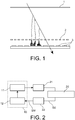
- FIG. 1 a diagram of a gas detector of type MICROMEGAS (for MICRO MEesh GAseous Structure).
- MICROMEGAS for MICRO MEesh GAseous Structure.
- the other electrode By applying a second electric field between this micro-gate and read tracks 3 (and therefore a second high voltage V2 is on the micro-grid or on the tracks, the other electrode is generally put at the potential of the mass), the electrons cross the micro-grid and multiply (avalanche phenomenon) thus inducing a significant signal on the tracks connected to a reading electronics.
- the average size of the avalanche ie the multiplicative factor of the electrons, called gain of the detector
- the average size of the avalanche, and therefore the amplitude of the resulting signal therefore depends on many parameters, both environmental (temperature, pressure) and related to the composition of the gas (presence of additives, pollutants, humidity, etc.). However, variations of these parameters are frequent, and modify the average amplitude of the signals.
- an object of the invention is to provide a more efficient feedback system.
- the feedback device further comprises a noise discrimination unit adapted to determine that a measurement signal delivered by the electronic reading unit is not noise so as to eliminate, at least partially, the noise in the calculation. of the statistical indicator.
- the invention relates to a method and a feedback device for a gas ionization particle detector.
- the invention is not limited to a MICROMEGAS type detector as illustrated in FIG. figure 1 but extends to any type of gaseous detector, such as for example a GEM detector (for Gas Electron Multiplier), a drift chamber or a Time Projection Chamber (TPC).
- GEM detector for Gas Electron Multiplier
- TPC Time Projection Chamber
- the gas ionization particle detector comprises a gas chamber 20 (ie a gas-containing detection chamber) in which are placed electrodes and a high voltage generator 21 adapted to create a potential difference between the electrodes.
- a gas chamber 20 ie a gas-containing detection chamber
- a high voltage generator 21 adapted to create a potential difference between the electrodes.
- the detector further comprises a readout electronics 22 adapted to collect an electric signal SE (charge or current) induced by a particle in the enclosure to provide a measurement signal SM.
- SE charge or current
- the read electronics 22 can sample the electrical signal SE and thus provide for measuring signal SM a signal representative of the shape of the electric signal induced by a particle.
- the reading electronics can directly integrate the induced electrical signal SE and provide for measurement signal SM a signal directly representative of the amplitude of the electrical signal induced by each particle in the enclosure, if necessary with an associated quantity ( as for example the time above a threshold).
- the feedback device 10 comprises a voltage regulator 11 configured to calculate a characteristic indicator of the measurement signal SM delivered by the electronic reading unit 22 and to modify a voltage setpoint delivered to the high voltage generator 21 as a function of the characteristic indicator of the measurement signal.
- the voltage regulator 11 can determine (where appropriate) and store at least one magnitude representative of the amplitude of the electrical signal induced by each particle.
- the voltage regulator 11 thus accumulates several magnitudes representative of the amplitudes corresponding to a succession of incident particles passing through the enclosure 20 of the gaseous detector. This accumulation is carried out over a sufficient long time (for example a few minutes) to have a good estimate of the characteristic indicator, and sufficiently short before the variations to be corrected. In practice, this accumulation can be performed for a given number of collections of a particle-induced electrical signal. For example, the accumulation of signals induced by a few hundred particles can be sufficient to have adequate accuracy. Alternatively, the accumulation of particle-induced signals is performed over a time window.
- the feedback according to the invention uses a characteristic indicator of the signals induced by the particles in the detector, for example a magnitude representative of the amplitudes of these signals.
- This feedback is therefore direct, in that it is done on the variable that we want to adjust, and not on intermediate parameters that affect this variable.
- This feedback thus makes it possible to correct all or part of the variations of the parameters influencing the gain of the detector.
- This is of course the case of environmental parameters but also of parameters related to the composition of the gaseous mixture which can be modified in time (gas leakage, degassing of a component, etc.), or else various factors modifying the gain (for example the appearance of a leakage current) or a fault in the high-voltage supply system (for example when the value of the control high voltage does not correspond to the value actually applied).
- the characteristic indicator of the measurement signal may be a characteristic amplitude of the measurement signal, for example a mean or median amplitude, calculated for a given number of collections of a particle-induced electrical signal (ie on the basis of a given number of detected events) or on a predefined time window.
- the characteristic indicator of the measurement signal may be a characteristic time above a threshold, for example a mean or median time, calculated for a given number of collections of a particle-induced electrical signal or over a time window. predefined.
- the characteristic indicator of the measurement signal may be an integral of the measurement signal, for example a mean or median integral, calculated for a given number of collections of a particle-induced electrical signal or on a predefined time window.
- the characteristic indicator of the measurement signal may be a current induced in the detection chamber, for example an average current integrated over a predefined time window.
- the characteristic indicator of the measurement signal can be a number, or a fraction, of reading elements carrying a signal, for example a number or a mean or median fraction, calculated for a given number of collections of an induced electrical signal. by a particle or on a predefined time window.
- the voltage regulator 11 may in particular be configured to modify the voltage setpoint so as to minimize the difference between the characteristic indicator of the measurement signal and a predetermined value.
- This predetermined value can be chosen so that the detection efficiency of the detector is the best possible (close to 100% for a charged particle) by avoiding excessive saturation of the signals.
- a predetermined value is chosen below a value leading to the saturation of analog-digital converters that equip the reading electronics.
- the high voltage is increased (in absolute value), and vice versa.
- the simplest correction is to change the high voltage by an amount proportional to the difference between the calculated value and the predetermined value.
- Other functions, non-linear, or using previous values of high voltages, can also be applied in order to better stabilize the amplitude and to minimize phenomena of classical oscillations in feedback.
- the feedback device may be configured to select only the events that actually correspond to the passage of a particle thereby eliminating a portion of the potential noise.
- the feedback device comprises a noise discrimination unit 12 able to verify that the signals delivered by the electronic reading unit actually correspond to a particle and are therefore not noise, which makes it possible to eliminate less partially, noise signals in the calculation of the characteristic indicator.
- Spurious noises can effectively pass a threshold of detection and be wrongly considered as a physical signal by the feedback device. Their inclusion in the calculation of the characteristic indicator can therefore distort feedback.
- the identification of signals actually coming from a particle makes it possible to obtain a more robust and precise feedback.
- the voltage regulator 11 is thus configured to calculate the characteristic indicator of the measurement signal on the basis of samples of the measurement signal corresponding to a collection by the electronic reading unit 20 of an electrical signal determined as being No noise from the unit 12.
- the noise discrimination unit 12 may be configured to determine that an electrical signal collected by the electronic unit 20 is not noise and thus allow selection of an event when said event is detected at least a minimum number of times by the different reading tracks or even by different detection speakers capable of detecting the same particle.
- the noise discrimination unit 12 may be configured to verify that the positions of the recorded signals are on a possible path, for example a straight line.
- the unit 12 implements a trajectory reconstruction algorithm of linear regression type, shape recognition or Kalman filter for example.
- the voltage regulator 11 then calculates the characteristic indicator of the measurement signal on the basis of samples of the measurement signal corresponding to a collection by the electronic reading unit 20 of an electrical signal induced along the path of the signal. a particle reconstructed by the noise discrimination unit 12.
- the feedback device may be coupled to a plurality of detection enclosures which are capable of detecting the same particle. Each detection chamber can indeed measure the position of the particle, and we can verify with several speakers that the positions of the recorded signals are on a possible path.
- the feedback device can be implemented in a hardware (hardware) and / or software (software) way. It can be embedded on an electronic card, which can also house the reading electronics.
- the invention also relates to a computer program product comprising code instructions for the implementation of this control method, when said program is executed on a computer.
Landscapes
- General Physics & Mathematics (AREA)
- Physics & Mathematics (AREA)
- Health & Medical Sciences (AREA)
- Life Sciences & Earth Sciences (AREA)
- Engineering & Computer Science (AREA)
- Molecular Biology (AREA)
- Spectroscopy & Molecular Physics (AREA)
- High Energy & Nuclear Physics (AREA)
- Chemical & Material Sciences (AREA)
- Automation & Control Theory (AREA)
- Radar, Positioning & Navigation (AREA)
- Electromagnetism (AREA)
- Toxicology (AREA)
- Chemical Kinetics & Catalysis (AREA)
- Electrochemistry (AREA)
- Analytical Chemistry (AREA)
- Biochemistry (AREA)
- General Health & Medical Sciences (AREA)
- Immunology (AREA)
- Pathology (AREA)
- Other Investigation Or Analysis Of Materials By Electrical Means (AREA)
- Measurement Of Radiation (AREA)
Applications Claiming Priority (1)
| Application Number | Priority Date | Filing Date | Title |
|---|---|---|---|
| FR1757755A FR3070210B1 (fr) | 2017-08-18 | 2017-08-18 | Procede et dispositif de retroaction sur la haute tension d'un detecteur gazeux |
Publications (3)
| Publication Number | Publication Date |
|---|---|
| EP3444698A1 true EP3444698A1 (de) | 2019-02-20 |
| EP3444698C0 EP3444698C0 (de) | 2023-07-12 |
| EP3444698B1 EP3444698B1 (de) | 2023-07-12 |
Family
ID=60923585
Family Applications (1)
| Application Number | Title | Priority Date | Filing Date |
|---|---|---|---|
| EP18189311.6A Active EP3444698B1 (de) | 2017-08-18 | 2018-08-16 | Rückkopplungsverfahren und -vorrichtung für die hochspannung eines gasdetektors |
Country Status (4)
| Country | Link |
|---|---|
| US (1) | US10712313B2 (de) |
| EP (1) | EP3444698B1 (de) |
| CA (1) | CA3014002A1 (de) |
| FR (1) | FR3070210B1 (de) |
Citations (5)
| Publication number | Priority date | Publication date | Assignee | Title |
|---|---|---|---|---|
| JPS58187885A (ja) * | 1982-04-27 | 1983-11-02 | Rigaku Denki Kogyo Kk | 放射線計測装置 |
| EP0483007A2 (de) * | 1990-10-24 | 1992-04-29 | Schlumberger Limited | Neutronendetektor mit stabilisertem Gewinn |
| WO2011138631A1 (en) * | 2010-05-06 | 2011-11-10 | Eos Imaging | Radiographic imaging device and detector for a radiographic imaging device |
| US20150198723A1 (en) * | 2014-01-14 | 2015-07-16 | Mitsubishi Electric Corporation | Radiation monitoring device |
| EP2990831A1 (de) * | 2013-04-25 | 2016-03-02 | Hitachi Aloka Medical, Ltd. | Strahlungsmessinstrument |
Family Cites Families (12)
| Publication number | Priority date | Publication date | Assignee | Title |
|---|---|---|---|---|
| US3487222A (en) * | 1967-11-03 | 1969-12-30 | Bausch & Lomb | Automatic gain control for self-calibrating a detection system |
| US3800143A (en) * | 1972-02-16 | 1974-03-26 | Nucleonics Dev Co | Agc for radiation counter |
| DE2826484C2 (de) * | 1978-06-16 | 1982-08-26 | Laboratorium Prof. Dr. Rudolf Berthold, 7547 Wildbad | Regelverfahren zur automatischen Driftstabilisierung bei einer Strahlungsmessung und Verwendungen bei diesem Verfahren |
| JPS57125372A (en) * | 1981-01-28 | 1982-08-04 | Japan Atom Energy Res Inst | Measuring device of neutron and gamma rays |
| US4760252A (en) * | 1983-06-28 | 1988-07-26 | Schlumberger Technology Corporation | Well logging tool with an accelerator neutron source |
| US4999501A (en) * | 1985-08-27 | 1991-03-12 | Baylor College Of Medicine | High speed multiwire photon camera |
| US7304310B1 (en) * | 2003-11-21 | 2007-12-04 | Kla-Tencor Technologies Corp. | Methods and systems for inspecting a specimen using light scattered in different wavelength ranges |
| WO2008133710A2 (en) * | 2006-10-28 | 2008-11-06 | Integrated Sensors, Llc | Plasma panel based radiation detector |
| EP2237073B1 (de) * | 2009-03-30 | 2012-10-31 | Berthold Technologies GmbH & Co. KG | Verfahren und Vorrichtung zur Überwachung einer automatischen Driftkompensation |
| US8937275B2 (en) * | 2012-10-12 | 2015-01-20 | Thermo Fisher Scientific Inc. | Method and apparatus to monitor gain of a proportional counter including correcting the counting threshold of a pulse height spectrum |
| FR3002651B1 (fr) * | 2013-02-22 | 2015-04-10 | Areva Nc | Procede d'asservissement du gain et du zero d'un dispositif de comptage de photons a pixels multiples, et systeme de mesure de lumiere mettant en œuvre ce procede |
| JP6733677B2 (ja) * | 2015-09-30 | 2020-08-05 | 大日本印刷株式会社 | 核医学検査装置及び核医学検査方法 |
-
2017
- 2017-08-18 FR FR1757755A patent/FR3070210B1/fr not_active Expired - Fee Related
-
2018
- 2018-08-10 CA CA3014002A patent/CA3014002A1/fr active Pending
- 2018-08-10 US US15/929,038 patent/US10712313B2/en active Active
- 2018-08-16 EP EP18189311.6A patent/EP3444698B1/de active Active
Patent Citations (5)
| Publication number | Priority date | Publication date | Assignee | Title |
|---|---|---|---|---|
| JPS58187885A (ja) * | 1982-04-27 | 1983-11-02 | Rigaku Denki Kogyo Kk | 放射線計測装置 |
| EP0483007A2 (de) * | 1990-10-24 | 1992-04-29 | Schlumberger Limited | Neutronendetektor mit stabilisertem Gewinn |
| WO2011138631A1 (en) * | 2010-05-06 | 2011-11-10 | Eos Imaging | Radiographic imaging device and detector for a radiographic imaging device |
| EP2990831A1 (de) * | 2013-04-25 | 2016-03-02 | Hitachi Aloka Medical, Ltd. | Strahlungsmessinstrument |
| US20150198723A1 (en) * | 2014-01-14 | 2015-07-16 | Mitsubishi Electric Corporation | Radiation monitoring device |
Also Published As
| Publication number | Publication date |
|---|---|
| FR3070210A1 (fr) | 2019-02-22 |
| US20190056354A1 (en) | 2019-02-21 |
| US10712313B2 (en) | 2020-07-14 |
| EP3444698C0 (de) | 2023-07-12 |
| CA3014002A1 (fr) | 2019-02-18 |
| EP3444698B1 (de) | 2023-07-12 |
| FR3070210B1 (fr) | 2022-05-20 |
Similar Documents
| Publication | Publication Date | Title |
|---|---|---|
| US11656210B2 (en) | Gas sensing systems and methods of operation thereof | |
| Tammet | Continuous scanning of the mobility and size distribution of charged clusters and nanometer particles in atmospheric air and the Balanced Scanning Mobility Analyzer BSMA | |
| Nowack et al. | Machine learning calibration of low-cost NO 2 and PM 10 sensors: Non-linear algorithms and their impact on site transferability | |
| CN112352153A (zh) | 一种消除环境温湿度变化影响的气体检测系统及其方法 | |
| US20190145929A1 (en) | Sensing Systems and Methods for the Estimation of Analyte Concentration | |
| Thompson et al. | Field intercomparison of the gas/particle partitioning of oxygenated organics during the Southern Oxidant and Aerosol Study (SOAS) in 2013 | |
| Zhang et al. | A novel approach for simple statistical analysis of high-resolution mass spectra | |
| Ye et al. | Advanced characterization of industrial smoke: Particle composition and size analysis with single particle aerosol mass spectrometry and optimized machine learning | |
| EP0370923B1 (de) | Verfahren und Vorrichtung zur Detektion von Impulsen, veranlasst durch elektrostatische Entladungen von Körpern | |
| WO2017194647A1 (fr) | Procede et dispositif de determination de la densite de volumes rocheux ou d'edifices artificiels | |
| EP3444698B1 (de) | Rückkopplungsverfahren und -vorrichtung für die hochspannung eines gasdetektors | |
| Bean | Evaluation methods for low-cost particulate matter sensors | |
| EP3194929A1 (de) | System und verfahren zur detektion von partikeln | |
| WO2001067092A2 (fr) | Analyseur en continu de compose organiques volatils, dispositif et procede d'evaluation en continu de la qualite de l'air ambiant interieur et utilisation de ce dispositif pour le pilotage d'une installation de ventilation | |
| Zhang et al. | A technique for rapid source apportionment applied to ambient organic aerosol measurements from a thermal desorption aerosol gas chromatograph (TAG) | |
| WO2024243592A1 (en) | Full signal utilization in charge detection mass spectrometry (cdms) | |
| US20210025850A1 (en) | Spectrometry System | |
| LU81912A1 (fr) | Detecteur | |
| WO2023126509A1 (fr) | Procédé de calibration en énergie d'un détecteur spectrométrique | |
| Nemanič et al. | Argon impact on the quantification accuracy of a QMS in gas mixtures with nitrogen or carbon monoxide at very low partial pressures | |
| FR2570908A1 (fr) | Systeme de traitement des signaux electriques issus d'un detecteur de rayons x | |
| JP7229163B2 (ja) | 質量分析におけるディスカバリイオン電流の生成およびその利用 | |
| Pyle et al. | ECD-dual-column pesticide method verification by ion trap GC/MS and GC/MS/MS | |
| EP3918430B1 (de) | Spurengasleckerkennungssystem und entsprechende verwendung | |
| Rush et al. | Challenging the Database: Day-of-Analysis Calibration and UF Modeling for Reliable RRF Use in Medical Device Chemical Characterization |
Legal Events
| Date | Code | Title | Description |
|---|---|---|---|
| PUAI | Public reference made under article 153(3) epc to a published international application that has entered the european phase |
Free format text: ORIGINAL CODE: 0009012 |
|
| STAA | Information on the status of an ep patent application or granted ep patent |
Free format text: STATUS: REQUEST FOR EXAMINATION WAS MADE |
|
| 17P | Request for examination filed |
Effective date: 20180816 |
|
| AK | Designated contracting states |
Kind code of ref document: A1 Designated state(s): AL AT BE BG CH CY CZ DE DK EE ES FI FR GB GR HR HU IE IS IT LI LT LU LV MC MK MT NL NO PL PT RO RS SE SI SK SM TR |
|
| AX | Request for extension of the european patent |
Extension state: BA ME |
|
| STAA | Information on the status of an ep patent application or granted ep patent |
Free format text: STATUS: EXAMINATION IS IN PROGRESS |
|
| 17Q | First examination report despatched |
Effective date: 20210420 |
|
| GRAP | Despatch of communication of intention to grant a patent |
Free format text: ORIGINAL CODE: EPIDOSNIGR1 |
|
| STAA | Information on the status of an ep patent application or granted ep patent |
Free format text: STATUS: GRANT OF PATENT IS INTENDED |
|
| RIC1 | Information provided on ipc code assigned before grant |
Ipc: G01T 1/185 20060101ALI20230216BHEP Ipc: G05F 1/46 20060101AFI20230216BHEP |
|
| INTG | Intention to grant announced |
Effective date: 20230306 |
|
| GRAS | Grant fee paid |
Free format text: ORIGINAL CODE: EPIDOSNIGR3 |
|
| GRAA | (expected) grant |
Free format text: ORIGINAL CODE: 0009210 |
|
| STAA | Information on the status of an ep patent application or granted ep patent |
Free format text: STATUS: THE PATENT HAS BEEN GRANTED |
|
| AK | Designated contracting states |
Kind code of ref document: B1 Designated state(s): AL AT BE BG CH CY CZ DE DK EE ES FI FR GB GR HR HU IE IS IT LI LT LU LV MC MK MT NL NO PL PT RO RS SE SI SK SM TR |
|
| REG | Reference to a national code |
Ref country code: CH Ref legal event code: EP |
|
| REG | Reference to a national code |
Ref country code: DE Ref legal event code: R096 Ref document number: 602018053113 Country of ref document: DE |
|
| REG | Reference to a national code |
Ref country code: IE Ref legal event code: FG4D Free format text: LANGUAGE OF EP DOCUMENT: FRENCH |
|
| U01 | Request for unitary effect filed |
Effective date: 20230804 |
|
| U07 | Unitary effect registered |
Designated state(s): AT BE BG DE DK EE FI FR IT LT LU LV MT NL PT SE SI Effective date: 20230811 |
|
| REG | Reference to a national code |
Ref country code: LT Ref legal event code: MG9D |
|
| U20 | Renewal fee for the european patent with unitary effect paid |
Year of fee payment: 6 Effective date: 20231106 |
|
| PG25 | Lapsed in a contracting state [announced via postgrant information from national office to epo] |
Ref country code: GR Free format text: LAPSE BECAUSE OF FAILURE TO SUBMIT A TRANSLATION OF THE DESCRIPTION OR TO PAY THE FEE WITHIN THE PRESCRIBED TIME-LIMIT Effective date: 20231013 |
|
| PG25 | Lapsed in a contracting state [announced via postgrant information from national office to epo] |
Ref country code: ES Free format text: LAPSE BECAUSE OF FAILURE TO SUBMIT A TRANSLATION OF THE DESCRIPTION OR TO PAY THE FEE WITHIN THE PRESCRIBED TIME-LIMIT Effective date: 20230712 |
|
| PG25 | Lapsed in a contracting state [announced via postgrant information from national office to epo] |
Ref country code: IS Free format text: LAPSE BECAUSE OF FAILURE TO SUBMIT A TRANSLATION OF THE DESCRIPTION OR TO PAY THE FEE WITHIN THE PRESCRIBED TIME-LIMIT Effective date: 20231112 |
|
| PG25 | Lapsed in a contracting state [announced via postgrant information from national office to epo] |
Ref country code: RS Free format text: LAPSE BECAUSE OF FAILURE TO SUBMIT A TRANSLATION OF THE DESCRIPTION OR TO PAY THE FEE WITHIN THE PRESCRIBED TIME-LIMIT Effective date: 20230712 Ref country code: NO Free format text: LAPSE BECAUSE OF FAILURE TO SUBMIT A TRANSLATION OF THE DESCRIPTION OR TO PAY THE FEE WITHIN THE PRESCRIBED TIME-LIMIT Effective date: 20231012 Ref country code: IS Free format text: LAPSE BECAUSE OF FAILURE TO SUBMIT A TRANSLATION OF THE DESCRIPTION OR TO PAY THE FEE WITHIN THE PRESCRIBED TIME-LIMIT Effective date: 20231112 Ref country code: HR Free format text: LAPSE BECAUSE OF FAILURE TO SUBMIT A TRANSLATION OF THE DESCRIPTION OR TO PAY THE FEE WITHIN THE PRESCRIBED TIME-LIMIT Effective date: 20230712 Ref country code: GR Free format text: LAPSE BECAUSE OF FAILURE TO SUBMIT A TRANSLATION OF THE DESCRIPTION OR TO PAY THE FEE WITHIN THE PRESCRIBED TIME-LIMIT Effective date: 20231013 Ref country code: ES Free format text: LAPSE BECAUSE OF FAILURE TO SUBMIT A TRANSLATION OF THE DESCRIPTION OR TO PAY THE FEE WITHIN THE PRESCRIBED TIME-LIMIT Effective date: 20230712 |
|
| PG25 | Lapsed in a contracting state [announced via postgrant information from national office to epo] |
Ref country code: PL Free format text: LAPSE BECAUSE OF FAILURE TO SUBMIT A TRANSLATION OF THE DESCRIPTION OR TO PAY THE FEE WITHIN THE PRESCRIBED TIME-LIMIT Effective date: 20230712 |
|
| REG | Reference to a national code |
Ref country code: CH Ref legal event code: PL |
|
| REG | Reference to a national code |
Ref country code: DE Ref legal event code: R097 Ref document number: 602018053113 Country of ref document: DE |
|
| PG25 | Lapsed in a contracting state [announced via postgrant information from national office to epo] |
Ref country code: SM Free format text: LAPSE BECAUSE OF FAILURE TO SUBMIT A TRANSLATION OF THE DESCRIPTION OR TO PAY THE FEE WITHIN THE PRESCRIBED TIME-LIMIT Effective date: 20230712 Ref country code: RO Free format text: LAPSE BECAUSE OF FAILURE TO SUBMIT A TRANSLATION OF THE DESCRIPTION OR TO PAY THE FEE WITHIN THE PRESCRIBED TIME-LIMIT Effective date: 20230712 Ref country code: CZ Free format text: LAPSE BECAUSE OF FAILURE TO SUBMIT A TRANSLATION OF THE DESCRIPTION OR TO PAY THE FEE WITHIN THE PRESCRIBED TIME-LIMIT Effective date: 20230712 Ref country code: MC Free format text: LAPSE BECAUSE OF FAILURE TO SUBMIT A TRANSLATION OF THE DESCRIPTION OR TO PAY THE FEE WITHIN THE PRESCRIBED TIME-LIMIT Effective date: 20230712 Ref country code: CH Free format text: LAPSE BECAUSE OF NON-PAYMENT OF DUE FEES Effective date: 20230831 Ref country code: SK Free format text: LAPSE BECAUSE OF FAILURE TO SUBMIT A TRANSLATION OF THE DESCRIPTION OR TO PAY THE FEE WITHIN THE PRESCRIBED TIME-LIMIT Effective date: 20230712 |
|
| PLBE | No opposition filed within time limit |
Free format text: ORIGINAL CODE: 0009261 |
|
| STAA | Information on the status of an ep patent application or granted ep patent |
Free format text: STATUS: NO OPPOSITION FILED WITHIN TIME LIMIT |
|
| REG | Reference to a national code |
Ref country code: IE Ref legal event code: MM4A |
|
| 26N | No opposition filed |
Effective date: 20240415 |
|
| PG25 | Lapsed in a contracting state [announced via postgrant information from national office to epo] |
Ref country code: IE Free format text: LAPSE BECAUSE OF NON-PAYMENT OF DUE FEES Effective date: 20230816 |
|
| PG25 | Lapsed in a contracting state [announced via postgrant information from national office to epo] |
Ref country code: IE Free format text: LAPSE BECAUSE OF NON-PAYMENT OF DUE FEES Effective date: 20230816 |
|
| U20 | Renewal fee for the european patent with unitary effect paid |
Year of fee payment: 7 Effective date: 20240822 |
|
| U1H | Name or address of the proprietor changed after the registration of the unitary effect |
Owner name: COMMISSARIAT A L'ENERGIE ATOMIQUE ET AUX ENERGIESALTERNATIVES; FR |
|
| PG25 | Lapsed in a contracting state [announced via postgrant information from national office to epo] |
Ref country code: CY Free format text: LAPSE BECAUSE OF FAILURE TO SUBMIT A TRANSLATION OF THE DESCRIPTION OR TO PAY THE FEE WITHIN THE PRESCRIBED TIME-LIMIT; INVALID AB INITIO Effective date: 20180816 |
|
| PG25 | Lapsed in a contracting state [announced via postgrant information from national office to epo] |
Ref country code: HU Free format text: LAPSE BECAUSE OF FAILURE TO SUBMIT A TRANSLATION OF THE DESCRIPTION OR TO PAY THE FEE WITHIN THE PRESCRIBED TIME-LIMIT; INVALID AB INITIO Effective date: 20180816 |
|
| U20 | Renewal fee for the european patent with unitary effect paid |
Year of fee payment: 8 Effective date: 20250826 |
|
| PGFP | Annual fee paid to national office [announced via postgrant information from national office to epo] |
Ref country code: GB Payment date: 20250825 Year of fee payment: 8 |
|
| U1N | Appointed representative for the unitary patent procedure changed after the registration of the unitary effect |
Representative=s name: SANTARELLI; FR |
|
| PG25 | Lapsed in a contracting state [announced via postgrant information from national office to epo] |
Ref country code: TR Free format text: LAPSE BECAUSE OF FAILURE TO SUBMIT A TRANSLATION OF THE DESCRIPTION OR TO PAY THE FEE WITHIN THE PRESCRIBED TIME-LIMIT Effective date: 20230712 |