EP3444833B1 - Boîte de kit de commutateurs de commande/auxiliaire pour un dispositif de commutation moyenne tension - Google Patents
Boîte de kit de commutateurs de commande/auxiliaire pour un dispositif de commutation moyenne tension Download PDFInfo
- Publication number
- EP3444833B1 EP3444833B1 EP17186114.9A EP17186114A EP3444833B1 EP 3444833 B1 EP3444833 B1 EP 3444833B1 EP 17186114 A EP17186114 A EP 17186114A EP 3444833 B1 EP3444833 B1 EP 3444833B1
- Authority
- EP
- European Patent Office
- Prior art keywords
- auxiliary
- medium voltage
- control switches
- switching device
- switches
- Prior art date
- Legal status (The legal status is an assumption and is not a legal conclusion. Google has not performed a legal analysis and makes no representation as to the accuracy of the status listed.)
- Active
Links
Images





Classifications
-
- H—ELECTRICITY
- H01—ELECTRIC ELEMENTS
- H01H—ELECTRIC SWITCHES; RELAYS; SELECTORS; EMERGENCY PROTECTIVE DEVICES
- H01H71/00—Details of the protective switches or relays covered by groups H01H73/00 - H01H83/00
- H01H71/02—Housings; Casings; Bases; Mountings
- H01H71/0207—Mounting or assembling the different parts of the circuit breaker
-
- H—ELECTRICITY
- H01—ELECTRIC ELEMENTS
- H01H—ELECTRIC SWITCHES; RELAYS; SELECTORS; EMERGENCY PROTECTIVE DEVICES
- H01H71/00—Details of the protective switches or relays covered by groups H01H73/00 - H01H83/00
- H01H71/02—Housings; Casings; Bases; Mountings
- H01H71/0207—Mounting or assembling the different parts of the circuit breaker
- H01H71/0228—Mounting or assembling the different parts of the circuit breaker having provisions for interchangeable or replaceable parts
-
- H—ELECTRICITY
- H01—ELECTRIC ELEMENTS
- H01H—ELECTRIC SWITCHES; RELAYS; SELECTORS; EMERGENCY PROTECTIVE DEVICES
- H01H71/00—Details of the protective switches or relays covered by groups H01H73/00 - H01H83/00
- H01H71/10—Operating or release mechanisms
-
- H—ELECTRICITY
- H01—ELECTRIC ELEMENTS
- H01H—ELECTRIC SWITCHES; RELAYS; SELECTORS; EMERGENCY PROTECTIVE DEVICES
- H01H71/00—Details of the protective switches or relays covered by groups H01H73/00 - H01H83/00
- H01H71/10—Operating or release mechanisms
- H01H71/12—Automatic release mechanisms with or without manual release
- H01H71/46—Automatic release mechanisms with or without manual release having means for operating auxiliary contacts additional to the main contacts
- H01H71/465—Self-contained, easily replaceable microswitches
Definitions
- the present invention relates to an auxiliary/control switches kit box for a Medium Voltage switching device, in particular for a Medium Voltage contactor, more in particular for a Medium Voltage vacuum contactor.
- MV medium voltage
- MV relates to operating voltages at electric power distribution levels, which are higher than 1 kV AC and 1.5 kV DC up to some tens of kV, e.g. up to 72 kV AC and 100 kV DC.
- a first type of switching devices including for example circuit breakers, is basically designed for protection purposes, namely for carrying (for a specified time interval) and breaking currents under specified abnormal circuit conditions, e.g. under short circuit conditions.
- a second type of switching devices including for example contactors, is basically designed for manoeuvring purposes, namely for carrying and breaking currents under normal circuit conditions including overload conditions.
- MV vacuum contactors represent a widely used type of MV contactors.
- Medium Voltage mechanical switching devices e.g. circuit breakers, contactors, disconnectors, and similar devices
- Auxiliary Switches which - according to the IEV 441-15-11 - are " a switch containing one or more control and / or auxiliary contacts mechanically operated by a switching device " and/or with the so called Control Switches which - according to the IEV 441-14-46 - are " mechanical switching device which serves the purpose of controlling the operation of switchgear or control gear, including signalling, electrical interlocking, etc .”
- the most common Auxiliary (or Control) Switches are those indicating the open/close status of the main switching device (i.e., the Make and Break contacts according to IEV 441-15-12 and 441-15-13]. It means that they are normally open (NO) in case of main device open and normally closed (NC) in case of main device closed (or vice versa).
- auxiliary switches are generally grouped in a set of a number "n" of switches (NC + NO) and linked to the main switch mechanism kinematics.
- the opening/closing of the auxiliary/control switches is driven by the opening/closing of the main switch mechanism of the Medium Voltage mechanical switching device.
- an auxiliary/control switch system In general, the operability of an auxiliary/control switch system must fulfil the requirements of existing Standards. For instance, according to IEC 62271-1 and derived Standards, an auxiliary switch operated in conjunction with the main contacts of a switching device shall be positively driven in both opening and closing directions.
- the standard also defines 3 classes of aux switches according to their breaking capacity, where class 1 has the highest performances.
- auxiliary/control switch systems should also meet the market requirements, as well as manufacturing and maintenance issues
- a set of auxiliary/control switches mounted on a Medium Voltage switching device should be easily mounted on the main switching device by the manufacturer, should be easily wired, and easily accessible/replaceable for service/maintenance activities. Also, the direct access to the auxiliary/control switches terminals by the final user is anyway not recommended and it is preferable to provide access to the customer only via terminal board interface.
- the Medium Voltage contactor and in particular the Medium Voltage vacuum contactors, represent a particular case, since their main switching mechanism generally operate with small strokes and small operating energies compared to circuit-breakers or other kind of switches.
- a first family of known kinds of auxiliary/control switches is represented by the Rotating auxiliary switches which however are hardly suitable for applications on Medium Voltage contactor, due to the need of high rotational strokes and therefore dedicated levers kinematics that may have an impact on the actuating force of the main drive, especially where high breaking class is required (and therefore with high auxiliary switch stroke).
- a second family of auxiliary/control switches is represented by the Linear auxiliary switches which are instead easily operated by, e.g., Medium Voltage vacuum contactor.
- the state-of art solutions require a fine stroke adjustment by the manufacturer during the assembling phase, that is time consuming and reduces the reliability of the system.
- auxiliary/control switches for a Medium Voltage switching device of known type is given in EP2346060 .
- Examples of auxiliary/control switches for low voltage switching devices, which are unsuited for use in the Medium Voltage field, are given in US5440088 and WO2009/095330 .
- the main aim of the present invention is to provide an auxiliary/control switches system for a Medium Voltage switching device, in particular for a Medium Voltage contactor, more in particular for Medium Voltage vacuum contactor, that allows solving or mitigating the above-mentioned problems.
- the present invention is aimed at providing an auxiliary/control switches system for a Medium Voltage switching device, in particular for a Medium Voltage contactor, more in particular for Medium Voltage vacuum contactor, that can be easily installed on said switching device and easily removed therefrom for maintenance and replacement during service.
- the present invention is aimed at providing an auxiliary/control switches system for a Medium Voltage switching device, in particular for a Medium Voltage contactor, more in particular for Medium Voltage vacuum contactor, that does not have any need of stroke adjustment or set-up during installation.
- the present invention is aimed at providing an auxiliary/control switches system for a Medium Voltage switching device, in particular for a Medium Voltage contactor, more in particular for Medium Voltage vacuum contactor, that is applicable on switching devices with small contact stroke, such as Medium Voltage vacuum contactors, with no need of multiple levers transmission.
- Still a further of the present invention is to provide an auxiliary/control switches system for a Medium Voltage switching device, in particular for a Medium Voltage contactor, more in particular for Medium Voltage vacuum contactor, in which the end-users do not have direct access to the auxiliary/control switches terminals.
- Yet a further of the present invention is to provide an auxiliary/control switches system for a Medium Voltage switching device, in particular for a Medium Voltage contactor, more in particular for Medium Voltage vacuum contactor, which does not require the presence of springs or similar actuating systems for the switching operation thereof.
- Still another object of the present invention is to provide an auxiliary/control switches system for a Medium Voltage switching device, in particular for a Medium Voltage contactor, more in particular for Medium Voltage vacuum contactor, that can be easily manufactured at industrial level, at competitive costs with respect to the solutions of the state of the art.
- the present invention also relates to a Medium Voltage switching device, in particular a Medium Voltage contactor, more in particular a Medium Voltage vacuum contactor, comprising an auxiliary/control switches as described herein.
- the present invention provides an auxiliary/control switches kit box for a Medium Voltage switching device comprising one or more movable contacts operated between a contact open position and a contact closed position by a kinematic chain connected to a contact actuator.
- the auxiliary/control switches kit box is characterized in that it comprises: a shaped enclosure adapted to be inserted into and removed from a dedicated volume inside said Medium Voltage switching device; said shaped enclosure housing one or more auxiliary/control switches electrically connected to corresponding one or more terminal boards; said one or more terminal boards facing toward the outside of said shaped enclosure from a first face of said shaped enclosure; said one or more auxiliary/control switches each comprising a pair of auxiliary/control switch contacts that can be linearly operated by an auxiliary/control switch actuator between a normally open (NO) position and a normally closed (NC) position; the auxiliary/control switches kit box further comprising a mechanical coupling system mechanically connected to said auxiliary/control switch actuator to linearly displace it between said NO position and said NC position; said mechanically coupling system having one or more operating levers protruding outside said shaped enclosure from a second face thereof and being adapted to cooperate with the kinematic chain of said Medium Voltage switching device and follow it during the movement from said contact open
- the auxiliary/control switches can be pre-wired in factory with the terminal board, and the full assembly of switches and terminal boards is included in a box, e.g., a plastic box.
- the fixation of the box to the frame of the Medium Voltage switching device can be done either by means of screw means or by alternative fastening methods (e.g., snap-fit fixing, sliding surface joints, and similar quick fixing systems).
- the assembling time and assembling complexity are therefore greatly reduced and the kit box can be easily installed, and is also easily removable for maintenance and replacement during service.
- the end-users can have easy access to the terminal board of the box positioned ,e.g., on the front of the Medium Voltage switching device, without direct access to the auxiliary/control switches terminals, thereby greatly improving the safety of the system.
- the auxiliary/control switches kit box is particularly useful in conjunction with Medium Voltage contactors, in particular Medium Voltage vacuum contactors, and other switching devices with small contact stroke, since it requires only small displacements to be operated, thereby avoiding any need of multiple levers transmission.
- a linear movement, e.g. vertical movement, of the drive kinematics of the Medium Voltage switching device during opening/closing operation thereof positively drives the movement of the operating levers of the auxiliary/control switches that open/close accordingly. Consequently, the switching of the auxiliary/control switches is always positively driven in both directions, i.e. there is no need of spring or similar means to drive one of the switching directions.
- said one or more auxiliary/control switches are double break switches. Double break switches and micro switches are well known in the art and will not be described in details.
- Such switches comprise a casing into which corresponding auxiliary/control switch contacts are housed (e.g., NC and NO switches).
- An auxiliary/control switch actuator is operatively connected to the auxiliary/control switch contacts to drive the commutation of, e.g., the NC and NO switches included in the casing.
- each of said double break switches is associated with at least a corresponding operating lever which is operatively connected to the auxiliary/control switch actuator.
- Said operating lever is adapted to be operatively connected to the kinematic chain of the Medium Voltage switching device into which the auxiliary/control switches kit box is placed.
- the one or more auxiliary/control switches can be conventional double break switches having a switch actuator which comprises a linearly moving driving pin acting on the auxiliary/control switch contacts to commute their position.
- the driving pin is connected to and operated by a corresponding operating lever, in turn operated by the kinematic chain of the Medium Voltage switching device.
- the driving pin of the double break switches since the driving pin of the double break switches has a small operating stroke, it can be operated by the kinematics of the Medium Voltage switching device, even if it has relatively low displacements, without any need of multiple levers transmission or similar systems of stroke enhancement.
- the terminals boards and the operating levers respectively protrude outside the shaped enclosure from a first and second face of said shaped enclosure which are substantially opposite to each other.
- kit box of the present invention can be inserted, e.g., horizontally, in a dedicate volume inside the Medium Voltage switching device so that the operating levers con couple with the kinematic chain of the Medium Voltage switching device.
- the terminals boards remain are positioned on an opposite side of the shaped enclosure, they lay on the front side of Medium Voltage switching device, thereby being easily accessible by the operators.
- the auxiliary/control switches kit box is also endowed with a high flexibility of us. Indeed, the number of auxiliary/control switches positioned inside the shaped enclosure, as well as their layout inside the shaped enclosure, can vary depending on the needs. In general, for most applications, the shaped enclosure houses a set of two or more linearly actuated auxiliary/control switches.
- the shaped enclosure is provided with snap-fitting means and/or sliding means and/or fixing means for guiding the insertion of said auxiliary/control switches kit box inside the dedicated volume of said Medium Voltage switching device and/or for fixing said shaped enclosure in its operative position inside said dedicated volume.
- Complementary snap-fitting means and/or sliding means and/or fixing means can be normally be provided in the Medium Voltage switching device intended to house the auxiliary/control switches kit box of the present invention.
- the present invention also relates to a Medium Voltage switching device, in particular a Medium Voltage contactor, more in particular a Medium Voltage contactor comprising an auxiliary/control switches kit box as described herein.
- Medium Voltage switching device are well known in the art and will not be described in details. They generally have one or more movable contacts which are operated between a contact open position and a contact closed position by a contact actuator which is connected to said one or more movable contacts through a kinematic chain to carry out the opening and closing operations of the Medium Voltage switching device.
- Medium Voltage contactors and contactor poles e.g., Medium Voltage vacuum contactors and vacuum contactor poles
- driving actuators are described in patent applications EP16174129 , EP16191442 , and EP16198880 , whose description is incorporated herein by reference.
- the contact actuator of the Medium Voltage contactor is a linear actuator comprising an operating element linearly moving between a contact open position and a contact closed position.
- the contact actuator typically comprises electromagnetic means which are energized to move said one or more movable contacts from said contact open position to said contact closed position, and spring means which moves said one or more contacts from said contact closed position to said contact open position.
- the Medium Voltage contactor further comprises a linearly moving operating element that can be operatively coupled with the operating levers of the previously described auxiliary/control switches kit box.
- the contact actuator can be a linear monostable electromagnetic actuator which comprises a coil, a fixed armature and a movable plunger, where the plunger is linearly moving to actuate the opening/closing operations of the contactor and is connected to the one or more contact(s) of the contactor via the mechanical link.
- the Medium Voltage contactor further comprises a linearly moving operating element that is connected to the mechanical link and can be operatively coupled with the operating levers of the previously described auxiliary/control switches kit box.
- the operating element can advantageously comprise a number of slots into which said one or more operating levers are inserted to operatively connect the auxiliary/control switches kit box to the Medium Voltage contactor.
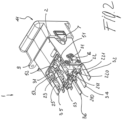
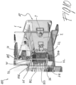
- an auxiliary/control switches kit box according to the invention - designated by the reference numeral 1 - is adapted to be used with a Medium Voltage switching device, preferably a Medium Voltage contactor or vacuum contactor - designated by the reference numeral 100.
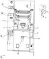
- the Medium Voltage switching device 100 generally comprises one or more movable contacts (not shown) which are operated between a contact open position (as partially shown in figure 9 ) and a contact closed position (as partially shown in figure 10 ).
- Movement of the contact is generally carried out by a contact actuator 102 (only partially shown in some figures) connected to the movable contact(s) through a kinematic chain 101 (only partially shown in some figures).
- the auxiliary/control switches kit box 1 comprises in its more general definition, a shaped enclosure 2 which is adapted to be inserted into and removed from a dedicated volume 105 inside said Medium Voltage switching device 100.
- the shaped enclosure 2 houses one or more auxiliary/control switches 21, 22, 23, 24, 25, 26.
- the number of auxiliary/control switches 21, 22, 23, 24, 25, 26 can vary depending on the needs. For instance, in the relatively simple execution of figure 1 , only a pair of auxiliary/control switches 21, 22 is used, while in the embodiments of figures 2-4 , six, four and six auxiliary/control switches are respectively used.
- Said auxiliary/control switches 21, 22, 23, 24, 25, 26 are electrically connected to corresponding one or more terminal boards 61, 62, 63 which provide an interface for the users.
- said one or more terminal boards 61, 62, 63 are positioned so as to face toward the outside of said shaped enclosure 2 from a first face 41 of said shaped enclosure 2.
- the terminal boards 61, 62, 63 can advantageously lay on the front face of said Medium Voltage switching device and are easily accessible by an operator.
- the auxiliary/control switches 21, 22, 23, 24, 25, 26 comprise corresponding auxiliary/control switch contacts that can be linearly operated by an auxiliary/control switch actuator 51, 52, 53 between a normally open NO position and a normally closed NC position.
- a mechanically coupling system 3 having one or more operating levers 31, 32, 33, 34, 35, 36 which protrude outside said shaped enclosure 2 from a second face 42 thereof.
- the operating levers 31, 32, 33, 34, 35, 36 are connected, on one side, to a corresponding auxiliary/control switch actuators 51, 52, 53, 54 to linearly displace it between said NO position and said NC position, and on the other side, are adapted to cooperate with the kinematic chain 101 of said Medium Voltage switching device 100 and follow it during the movement from said contact open position and said contact closed position.
- the one or more auxiliary/control switches 21, 22, 23, 24, 25, 26 can be positively driven by the kinematic chain 101 of said Medium Voltage switching device 100 in both directions between said normally open NO position and said normally closed NC position, with no need of return means, e.g. spring means.
- said one or more auxiliary/control switches 21, 22, 23, 24, 25, 26 are double break switches or microswitches each comprising a casing 200 into which corresponding auxiliary/control switch contacts are housed.
- a switch or microswitch actuator 51, 52, 53, 54 is positioned on the casing 200 to drive the auxiliary/control switch contacts housed in said casing 200.
- Each actuator 51, 52, 53, 54 of said double break switches 21, 22, 23, 24, 25, 26 is associated with at least a corresponding operating lever 31, 32, 33, 34, 35, 36 which is connected to the kinematic chain of the Medium Voltage switching device as previously described.
- said one or more auxiliary/control switches are double break switches 21, 22, 23, 24, 25, 26, which are actuated by a linearly moving driving pin 51, 52, 53, 54 which is operatively connected to the auxiliary/control switch contacts and to a corresponding operating lever 31, 32, 33, 34, 35, 36.
- the electrical connection of the auxiliary/control switches is carried out through electrical terminals (e.g., 210, 221; 220, 221) and the whole system of said one or more auxiliary/control switches 21, 22, 23, 24, 25, 26 is advantageously pre-wired to a corresponding one or more terminal boards 61, 62, 63 before they are placed in said shaped enclosure 2.
- electrical terminals e.g., 210, 221; 220, 221
- the whole system of said one or more auxiliary/control switches 21, 22, 23, 24, 25, 26 is advantageously pre-wired to a corresponding one or more terminal boards 61, 62, 63 before they are placed in said shaped enclosure 2.
- said first 41 face (from which the terminal boards 61, 62, 63 protrude) and second face 42 (from which the operating lever 31, 32, 33, 34, 35, 36 protrude) of said shaped enclosure 2 are substantially opposite to each other.
- said shaped enclosure 2 comprises snap-fitting means 7 and/or sliding means 8 and/or fixing means 9 for guiding the insertion of said auxiliary/control switches kit box 1 inside the dedicated volume 105 of said Medium Voltage switching device 100 and/or for fixing said shaped enclosure 2 in its operative position inside said dedicated volume 105.
- the operative coupling of the takes place by linear insertion in the horizontal direction of the shaped enclosure 2 into a dedicated volume 105 inside the Medium Voltage switching device 100, with the second face 42 laying forward.
- the operating lever 31, 32, 33, 34, 35, 36 (which protrude from said second face 42) can be coupled with the kinematic chain 101 of said Medium Voltage switching device 100, as better described hereinafter.
- the first face 41 (and consequently the terminal boards 61, 62, 63) lays on the front side of the Medium Voltage switching device 100 and is therefore easily accessible by an operator. Insertion of the shaped enclosure 2 inside the dedicated volume 105 of said Medium Voltage switching device 100 can be made easier by using e.g. sliding means 8 adapted to slide in corresponding means (e.g. a shaped slot 81) provided in the Medium Voltage switching device 100.
- fixing can be carried out by using snap-fitting means 7 and/or fixing means 9 provided on the surface of the shaped enclosure 2 and/or on tabs protruding therefrom, adapted to be coupled with complementary snap-fitting and/or fixing means 71, 91, provided in the Medium Voltage switching device 100.
- the present invention also relates to a Medium Voltage switching device 100 comprising an auxiliary/control switches kit box 1 as described in the present disclosure.
- the present invention also relates to a Medium Voltage contactor, e.g. a vacuum contactor, 100 comprising an auxiliary/control switches kit box 1 as described in the present disclosure.
- a Medium Voltage contactor e.g. a vacuum contactor
- auxiliary/control switches kit box 1 as described in the present disclosure.
- a Medium Voltage contactor e.g. a vacuum contactor
- 100 generally comprises one or more movable contacts which are operated between a contact open position and a contact closed position by a contact actuator 102 which is connected to said one or more movable contacts through a kinematic chain 101 to carry out the opening and closing operations of the Medium Voltage switching device.
- the contact actuator 102 is a linear monostable electromagnetic actuator which comprises a coil, a fixed armature and a movable plunger, where the plunger is linearly moving to actuate the opening/closing operations of the contactor and is connected to the one or more contact(s) of the contactor via the mechanical link 101.
- the Medium Voltage contactor 100 further comprises a linearly moving operating element 103 that is connected to the mechanical link 101 and is operatively coupled with the operating levers 31, 32, 33, 34, 35, 36 of the previously described auxiliary/control switches 21, 22, 23, 24, 25, 26 of the kit box 1.
- auxiliary/control switches 21, 22, 23, 24, 25, 26 are positioned on two superimposed rows of auxiliary/control switches pairs (first row: switches 21, 23 25; second row: switches 22, 24, 26). Different numbers and different layouts for the auxiliary/control switches 21, 22, 23, 24, 25, 26 are also possible according to the needs.
- the operating element 103 is rigidly fixed to the mechanical link 101 and follows it in its linear moving between the contact open position ( figure 9 ) and the contact closed position ( figure 10 ).
- the operating element 103 connected to the mechanical link 101 of the contact actuator 102 comprises a two parallel slots 104 spaced apart in the vertical direction.
- the operating levers 31, 33, 35 of the first row of switches 21, 23, 25 are inserted in the upper slot, while the operating levers 32, 34, 36 of second row of switches 22, 24, 26 are inserted in the lower slot.
- the opposite sequence takes place when the contact(s) of the Medium Voltage switching device 100 are moved from the closed position to the open position.
- auxiliary/control switches kit box for a Medium Voltage switching device and to the Medium Voltage switching device thus conceived, all falling within the scope of the attached claims.
- materials used and the contingent dimensions and shapes can be any, according to requirements and to the state of the art.
Landscapes
- Driving Mechanisms And Operating Circuits Of Arc-Extinguishing High-Tension Switches (AREA)
- Mechanisms For Operating Contacts (AREA)
Claims (11)
- Boîte de kit de commutateurs auxiliaires/de commande (1) pour un dispositif de commutation moyenne tension (100), le dispositif de commutation moyenne tension (100) comprenant un ou plusieurs contacts mobiles actionnés entre une position contact ouvert et une position contact fermé par une chaîne cinématique (101) reliée à un actionneur de contact (102), caractérisée en ce que la boîte de kit de commutateurs auxiliaires/de commande (1) comprend : une enceinte profilée (2) adaptée pour être insérée au moins partiellement dans un volume dédié (105) à l'intérieur dudit dispositif de commutation moyenne tension (100) et pour être extraite de celui-ci ; ladite enceinte profilée (2) logeant un ou plusieurs commutateurs auxiliaires/de commande (21, 22, 23, 24, 25, 26) connectés électriquement à un ou plusieurs borniers correspondants (61, 62, 63) ; lesdits un ou plusieurs borniers (61, 62, 63) étant tournés vers l'extérieur de ladite enceinte profilée (2) à partir d'une première face (41) de ladite enceinte profilée (2) ; lesdits un ou plusieurs commutateurs auxiliaires/de commande (21, 22, 23, 24, 25, 26) comprenant chacun une paire de contacts de commutateurs auxiliaires/de commande qui sont aptes à être actionnés linéairement par un actionneur de commutateur auxiliaire/de commande (51, 52, 53, 54) entre une position normalement ouverte (NO) et une position normalement fermée (NC) ; le boîtier de kit de commutateurs auxiliaires/de commande (1) comprenant en outre un système de liaison mécanique (3) relié mécaniquement auxdits actionneurs de commutateurs auxiliaires/de commande (51, 52, 53) pour le déplacer linéairement entre ladite position NO et ladite position NC ; ledit système de liaison mécanique (3) ayant un ou plusieurs leviers de commande (31, 32, 33, 34, 35, 36) faisant saillie sur l'extérieur de ladite enceinte profilée (2) à partir d'une deuxième face (42) de celle-ci et étant adaptés pour coopérer avec la chaîne cinématique (101) dudit dispositif de commutation moyenne tension (100) et la suivre pendant le mouvement depuis ladite position d'ouverture de contact et ladite position de fermeture de contact, et lesdites première (41) et deuxième (42) faces de ladite enceinte profilée (2) sont sensiblement opposées l'une à l'autre.
- Boîte de kit de commutateurs auxiliaires/de commande (1), selon la revendication 1, caractérisée en ce que lesdits un ou plusieurs commutateurs auxiliaires/de commande (21, 22, 23, 24, 25, 26) sont des commutateurs à double coupure comprenant chacun un boîtier (200) dans lequel sont logés des contacts de commutateurs auxiliaires/de commande correspondants, chacun desdits commutateurs à double coupure étant associé à au moins un levier de commande correspondant (31, 32, 33, 34, 35, 36) qui est fonctionnellement connecté par l'intermédiaire d'un actionneur de commutateur auxiliaire/de commande correspondant (51, 52, 53) aux contacts de commutateur auxiliaire/de commande logés dans ledit boîtier (200).
- Boîte de kit de commutateurs auxiliaires/de commande (1), selon la revendication 1 ou la revendication 2, caractérisée en ce que lesdits un ou plusieurs commutateurs auxiliaires/de commande sont des commutateurs à double coupure (21, 22, 23, 24, 25, 26), et en ce que ledit actionneur de commutateur auxiliaire/de commande (51, 52, 53) comprend une broche d'entraînement à déplacement linéaire pour lesdits contacts de commutateur auxiliaire/de commande qui est fonctionnellement connectée auxdits contacts de commutateur auxiliaire/de commande et à un levier de commande correspondant (31, 32, 33, 34, 35, 36).
- Boîte de kit de commutateurs auxiliaires/de commande (1), selon une ou plusieurs des revendications précédentes, caractérisée en ce que ladite enceinte profilée (2) loge un ensemble de deux ou plusieurs commutateurs auxiliaires/de commande (21, 22, 23, 24, 25, 26) actionnés linéairement.
- Boîte de kit de commutateurs auxiliaires de commutateurs auxiliaires/de commande (1), selon une ou plusieurs des revendications précédentes, caractérisée en ce que ladite enceinte profilée (2) comprend des moyens d'encliquetage (7) et/ou des moyens de coulissement (8) et/ou des moyens de fixation (9) pour guider l'insertion de ladite boîte de kit de commutateurs auxiliaires/de commande (1) à l'intérieur du volume dédié (105) dudit dispositif de commutation moyenne tension (100) et/ou pour fixer ladite enceinte profilée (2) dans sa position fonctionnelle position à l'intérieur dudit volume dédié (105).
- Boîte de kit de commutateurs auxiliaires de commutateurs auxiliaires/de commande (1), selon une ou plusieurs des revendications précédentes, caractérisée en ce que lesdits un ou plusieurs commutateurs auxiliaires/de commande (21, 22, 23, 24, 25, 26) sont précâblés. à un ou plusieurs borniers correspondants (61, 62, 63) avant qu'ils ne soient placés dans ladite enceinte profilée (2).
- Boîte de kit de commutateurs auxiliaires/de commande (1), selon une ou plusieurs des revendications précédentes, caractérisée en ce que lesdits un ou plusieurs commutateurs auxiliaires/de commande (21, 22, 23, 24, 25, 26) sont adaptés pour être entraînés positivement par la chaîne cinématique (101) dudit dispositif de commutation moyenne tension (100) dans les deux directions entre ladite position normalement ouverte (NO) et ladite position normalement fermée (NC).
- Dispositif de commutation moyenne tension (100) caractérisé en ce qu'il comprend une boîte de kit de commutateurs auxiliaires/de commande (1) selon une ou plusieurs des revendications précédentes.
- Dispositif de commutation moyenne tension (100), selon la revendication 8, caractérisé en ce qu'il s'agit d'un contacteur moyenne tension.
- Contacteur moyenne tension (100), selon la revendication 9, caractérisé en ce que ledit actionneur de contact (102) est un actionneur linéaire comprenant un élément de manoeuvre (103) mobile linéairement entre une position contact ouvert et une position contact fermé.
- Contacteur moyenne tension (100), selon la revendication 10, caractérisé en en ce que l'élément de commande (103) dudit actionneur de contact (102) comprend un certain nombre de fentes (104) dans lesquelles lesdits un ou plusieurs leviers de commande (31, 32, 33, 34, 35, 36) sont insérés.
Priority Applications (5)
| Application Number | Priority Date | Filing Date | Title |
|---|---|---|---|
| ES17186114T ES2959861T3 (es) | 2017-08-14 | 2017-08-14 | Caja de kit de conmutadores auxiliares/de control para un dispositivo de conmutación de media tensión |
| EP17186114.9A EP3444833B1 (fr) | 2017-08-14 | 2017-08-14 | Boîte de kit de commutateurs de commande/auxiliaire pour un dispositif de commutation moyenne tension |
| CN201880038787.7A CN110914950B (zh) | 2017-08-14 | 2018-07-16 | 用于中压开关设备的辅助/控制开关套件盒 |
| US16/636,454 US10998156B2 (en) | 2017-08-14 | 2018-07-16 | Auxiliary/control switches kit box for a medium voltage switching device |
| PCT/EP2018/069281 WO2019034350A1 (fr) | 2017-08-14 | 2018-07-16 | Boîtier de kit de commutateurs auxiliaires/de commande pour un dispositif de commutation moyenne tension |
Applications Claiming Priority (1)
| Application Number | Priority Date | Filing Date | Title |
|---|---|---|---|
| EP17186114.9A EP3444833B1 (fr) | 2017-08-14 | 2017-08-14 | Boîte de kit de commutateurs de commande/auxiliaire pour un dispositif de commutation moyenne tension |
Publications (2)
| Publication Number | Publication Date |
|---|---|
| EP3444833A1 EP3444833A1 (fr) | 2019-02-20 |
| EP3444833B1 true EP3444833B1 (fr) | 2023-07-19 |
Family
ID=59626503
Family Applications (1)
| Application Number | Title | Priority Date | Filing Date |
|---|---|---|---|
| EP17186114.9A Active EP3444833B1 (fr) | 2017-08-14 | 2017-08-14 | Boîte de kit de commutateurs de commande/auxiliaire pour un dispositif de commutation moyenne tension |
Country Status (5)
| Country | Link |
|---|---|
| US (1) | US10998156B2 (fr) |
| EP (1) | EP3444833B1 (fr) |
| CN (1) | CN110914950B (fr) |
| ES (1) | ES2959861T3 (fr) |
| WO (1) | WO2019034350A1 (fr) |
Families Citing this family (1)
| Publication number | Priority date | Publication date | Assignee | Title |
|---|---|---|---|---|
| CN110676092B (zh) * | 2019-10-18 | 2025-02-28 | 中国铁道科学研究院集团有限公司 | 基于开关设备多路反馈信号的控制系统 |
Family Cites Families (6)
| Publication number | Priority date | Publication date | Assignee | Title |
|---|---|---|---|---|
| FR2696276B1 (fr) * | 1992-09-29 | 1994-12-02 | Merlin Gerin | Disjoncteur à boîtier moulé à contacts auxiliaires. |
| ITMI20080158A1 (it) * | 2008-01-31 | 2009-08-01 | Abb Spa | Dispositivo di interruzione per impianti di bassa tensione |
| ES2397075T3 (es) * | 2010-01-18 | 2013-03-04 | Abb Technology Ag | Disyuntor de media tensión |
| EP3258473B1 (fr) * | 2016-06-13 | 2019-08-07 | ABB Schweiz AG | Contacteur moyenne tension |
| EP3301700B1 (fr) | 2016-09-29 | 2023-03-29 | ABB Schweiz AG | Contacteur moyenne tension |
| EP3321950B1 (fr) | 2016-11-15 | 2019-08-28 | ABB Schweiz AG | Borne électrique pour unités de pôle électrique |
-
2017
- 2017-08-14 EP EP17186114.9A patent/EP3444833B1/fr active Active
- 2017-08-14 ES ES17186114T patent/ES2959861T3/es active Active
-
2018
- 2018-07-16 WO PCT/EP2018/069281 patent/WO2019034350A1/fr not_active Ceased
- 2018-07-16 CN CN201880038787.7A patent/CN110914950B/zh active Active
- 2018-07-16 US US16/636,454 patent/US10998156B2/en active Active
Also Published As
| Publication number | Publication date |
|---|---|
| CN110914950B (zh) | 2022-04-01 |
| US20200321179A1 (en) | 2020-10-08 |
| WO2019034350A1 (fr) | 2019-02-21 |
| ES2959861T3 (es) | 2024-02-28 |
| US10998156B2 (en) | 2021-05-04 |
| EP3444833A1 (fr) | 2019-02-20 |
| CN110914950A (zh) | 2020-03-24 |
Similar Documents
| Publication | Publication Date | Title |
|---|---|---|
| CN103367016B (zh) | 电气开关装置、电气设备以及开关柜 | |
| US10998156B2 (en) | Auxiliary/control switches kit box for a medium voltage switching device | |
| CN102891045A (zh) | 电气开关装置及其辅助脱扣机构 | |
| KR101939828B1 (ko) | 진공 인터럽터 타입 기체절연 개폐장치 | |
| KR101168257B1 (ko) | 전자석 엑츄레이터를 탑재한 전자식 배선용 차단기 | |
| KR100987585B1 (ko) | 배전반의 셀스위치 구동용 주축로드 | |
| CN109192627B (zh) | 一种控制与保护开关电器 | |
| CN109360763B (zh) | 一种新型空气绝缘真空断路器 | |
| CN202003869U (zh) | 带机械联锁的组合按钮开关装置 | |
| EP2722862B1 (fr) | Ensemble électrique pour appareillage de commutation et appareillage de commutation associé | |
| DE102008011522A1 (de) | Baureihe von modular aufgebauten Schaltgeräten zur wahlweisen Verwendung in der Niederspannung oder Mittelspannung sowie Schaltschrank hierfür | |
| US11688570B2 (en) | Switching device | |
| US4368443A (en) | Power electric circuit switching device | |
| EP3968351B1 (fr) | Relais électromagnétique | |
| CN120565354B (zh) | 分相独立控制的三相开关 | |
| CN210668146U (zh) | 集成断路器及电控柜 | |
| KR101874447B1 (ko) | 개폐장치가 구비된 접속재 | |
| EP4207228B1 (fr) | Relais électromagnétique pour la prévention de courts-circuits d'arc | |
| CN223539524U (zh) | 一种带接地功能的继电器 | |
| CN114242532B (zh) | 一种电磁式开关模组 | |
| KR102352082B1 (ko) | 수배전반, 분전반, 접속반, 제어반의 링케이지를 갖는 계전기 | |
| CN102956381B (zh) | 开关电器的机械及电气联锁装置 | |
| JP2025079603A (ja) | 開閉装置の機械式インターロック装置 | |
| JP2024507955A (ja) | 切換器及び切換器を有する負荷時タップ切換装置 | |
| CN119049926A (zh) | 一种带接地功能的继电器 |
Legal Events
| Date | Code | Title | Description |
|---|---|---|---|
| PUAI | Public reference made under article 153(3) epc to a published international application that has entered the european phase |
Free format text: ORIGINAL CODE: 0009012 |
|
| STAA | Information on the status of an ep patent application or granted ep patent |
Free format text: STATUS: THE APPLICATION HAS BEEN PUBLISHED |
|
| AK | Designated contracting states |
Kind code of ref document: A1 Designated state(s): AL AT BE BG CH CY CZ DE DK EE ES FI FR GB GR HR HU IE IS IT LI LT LU LV MC MK MT NL NO PL PT RO RS SE SI SK SM TR |
|
| AX | Request for extension of the european patent |
Extension state: BA ME |
|
| STAA | Information on the status of an ep patent application or granted ep patent |
Free format text: STATUS: REQUEST FOR EXAMINATION WAS MADE |
|
| 17P | Request for examination filed |
Effective date: 20190819 |
|
| RBV | Designated contracting states (corrected) |
Designated state(s): AL AT BE BG CH CY CZ DE DK EE ES FI FR GB GR HR HU IE IS IT LI LT LU LV MC MK MT NL NO PL PT RO RS SE SI SK SM TR |
|
| STAA | Information on the status of an ep patent application or granted ep patent |
Free format text: STATUS: EXAMINATION IS IN PROGRESS |
|
| 17Q | First examination report despatched |
Effective date: 20211012 |
|
| GRAP | Despatch of communication of intention to grant a patent |
Free format text: ORIGINAL CODE: EPIDOSNIGR1 |
|
| STAA | Information on the status of an ep patent application or granted ep patent |
Free format text: STATUS: GRANT OF PATENT IS INTENDED |
|
| INTG | Intention to grant announced |
Effective date: 20230224 |
|
| GRAS | Grant fee paid |
Free format text: ORIGINAL CODE: EPIDOSNIGR3 |
|
| GRAA | (expected) grant |
Free format text: ORIGINAL CODE: 0009210 |
|
| STAA | Information on the status of an ep patent application or granted ep patent |
Free format text: STATUS: THE PATENT HAS BEEN GRANTED |
|
| AK | Designated contracting states |
Kind code of ref document: B1 Designated state(s): AL AT BE BG CH CY CZ DE DK EE ES FI FR GB GR HR HU IE IS IT LI LT LU LV MC MK MT NL NO PL PT RO RS SE SI SK SM TR |
|
| REG | Reference to a national code |
Ref country code: GB Ref legal event code: FG4D |
|
| REG | Reference to a national code |
Ref country code: CH Ref legal event code: EP |
|
| REG | Reference to a national code |
Ref country code: DE Ref legal event code: R096 Ref document number: 602017071415 Country of ref document: DE |
|
| REG | Reference to a national code |
Ref country code: IE Ref legal event code: FG4D |
|
| REG | Reference to a national code |
Ref country code: LT Ref legal event code: MG9D |
|
| REG | Reference to a national code |
Ref country code: NL Ref legal event code: MP Effective date: 20230719 |
|
| REG | Reference to a national code |
Ref country code: AT Ref legal event code: MK05 Ref document number: 1590348 Country of ref document: AT Kind code of ref document: T Effective date: 20230719 |
|
| PG25 | Lapsed in a contracting state [announced via postgrant information from national office to epo] |
Ref country code: NL Free format text: LAPSE BECAUSE OF FAILURE TO SUBMIT A TRANSLATION OF THE DESCRIPTION OR TO PAY THE FEE WITHIN THE PRESCRIBED TIME-LIMIT Effective date: 20230719 |
|
| PG25 | Lapsed in a contracting state [announced via postgrant information from national office to epo] |
Ref country code: GR Free format text: LAPSE BECAUSE OF FAILURE TO SUBMIT A TRANSLATION OF THE DESCRIPTION OR TO PAY THE FEE WITHIN THE PRESCRIBED TIME-LIMIT Effective date: 20231020 |
|
| PG25 | Lapsed in a contracting state [announced via postgrant information from national office to epo] |
Ref country code: IS Free format text: LAPSE BECAUSE OF FAILURE TO SUBMIT A TRANSLATION OF THE DESCRIPTION OR TO PAY THE FEE WITHIN THE PRESCRIBED TIME-LIMIT Effective date: 20231119 |
|
| PG25 | Lapsed in a contracting state [announced via postgrant information from national office to epo] |
Ref country code: SE Free format text: LAPSE BECAUSE OF FAILURE TO SUBMIT A TRANSLATION OF THE DESCRIPTION OR TO PAY THE FEE WITHIN THE PRESCRIBED TIME-LIMIT Effective date: 20230719 Ref country code: RS Free format text: LAPSE BECAUSE OF FAILURE TO SUBMIT A TRANSLATION OF THE DESCRIPTION OR TO PAY THE FEE WITHIN THE PRESCRIBED TIME-LIMIT Effective date: 20230719 Ref country code: PT Free format text: LAPSE BECAUSE OF FAILURE TO SUBMIT A TRANSLATION OF THE DESCRIPTION OR TO PAY THE FEE WITHIN THE PRESCRIBED TIME-LIMIT Effective date: 20231120 Ref country code: NO Free format text: LAPSE BECAUSE OF FAILURE TO SUBMIT A TRANSLATION OF THE DESCRIPTION OR TO PAY THE FEE WITHIN THE PRESCRIBED TIME-LIMIT Effective date: 20231019 Ref country code: LV Free format text: LAPSE BECAUSE OF FAILURE TO SUBMIT A TRANSLATION OF THE DESCRIPTION OR TO PAY THE FEE WITHIN THE PRESCRIBED TIME-LIMIT Effective date: 20230719 Ref country code: LT Free format text: LAPSE BECAUSE OF FAILURE TO SUBMIT A TRANSLATION OF THE DESCRIPTION OR TO PAY THE FEE WITHIN THE PRESCRIBED TIME-LIMIT Effective date: 20230719 Ref country code: IS Free format text: LAPSE BECAUSE OF FAILURE TO SUBMIT A TRANSLATION OF THE DESCRIPTION OR TO PAY THE FEE WITHIN THE PRESCRIBED TIME-LIMIT Effective date: 20231119 Ref country code: HR Free format text: LAPSE BECAUSE OF FAILURE TO SUBMIT A TRANSLATION OF THE DESCRIPTION OR TO PAY THE FEE WITHIN THE PRESCRIBED TIME-LIMIT Effective date: 20230719 Ref country code: GR Free format text: LAPSE BECAUSE OF FAILURE TO SUBMIT A TRANSLATION OF THE DESCRIPTION OR TO PAY THE FEE WITHIN THE PRESCRIBED TIME-LIMIT Effective date: 20231020 Ref country code: FI Free format text: LAPSE BECAUSE OF FAILURE TO SUBMIT A TRANSLATION OF THE DESCRIPTION OR TO PAY THE FEE WITHIN THE PRESCRIBED TIME-LIMIT Effective date: 20230719 Ref country code: AT Free format text: LAPSE BECAUSE OF FAILURE TO SUBMIT A TRANSLATION OF THE DESCRIPTION OR TO PAY THE FEE WITHIN THE PRESCRIBED TIME-LIMIT Effective date: 20230719 |
|
| REG | Reference to a national code |
Ref country code: ES Ref legal event code: FG2A Ref document number: 2959861 Country of ref document: ES Kind code of ref document: T3 Effective date: 20240228 |
|
| PG25 | Lapsed in a contracting state [announced via postgrant information from national office to epo] |
Ref country code: PL Free format text: LAPSE BECAUSE OF FAILURE TO SUBMIT A TRANSLATION OF THE DESCRIPTION OR TO PAY THE FEE WITHIN THE PRESCRIBED TIME-LIMIT Effective date: 20230719 |
|
| REG | Reference to a national code |
Ref country code: CH Ref legal event code: PL |
|
| PG25 | Lapsed in a contracting state [announced via postgrant information from national office to epo] |
Ref country code: LU Free format text: LAPSE BECAUSE OF NON-PAYMENT OF DUE FEES Effective date: 20230814 |
|
| REG | Reference to a national code |
Ref country code: DE Ref legal event code: R097 Ref document number: 602017071415 Country of ref document: DE |
|
| PG25 | Lapsed in a contracting state [announced via postgrant information from national office to epo] |
Ref country code: SM Free format text: LAPSE BECAUSE OF FAILURE TO SUBMIT A TRANSLATION OF THE DESCRIPTION OR TO PAY THE FEE WITHIN THE PRESCRIBED TIME-LIMIT Effective date: 20230719 Ref country code: RO Free format text: LAPSE BECAUSE OF FAILURE TO SUBMIT A TRANSLATION OF THE DESCRIPTION OR TO PAY THE FEE WITHIN THE PRESCRIBED TIME-LIMIT Effective date: 20230719 Ref country code: LU Free format text: LAPSE BECAUSE OF NON-PAYMENT OF DUE FEES Effective date: 20230814 Ref country code: EE Free format text: LAPSE BECAUSE OF FAILURE TO SUBMIT A TRANSLATION OF THE DESCRIPTION OR TO PAY THE FEE WITHIN THE PRESCRIBED TIME-LIMIT Effective date: 20230719 Ref country code: DK Free format text: LAPSE BECAUSE OF FAILURE TO SUBMIT A TRANSLATION OF THE DESCRIPTION OR TO PAY THE FEE WITHIN THE PRESCRIBED TIME-LIMIT Effective date: 20230719 Ref country code: CZ Free format text: LAPSE BECAUSE OF FAILURE TO SUBMIT A TRANSLATION OF THE DESCRIPTION OR TO PAY THE FEE WITHIN THE PRESCRIBED TIME-LIMIT Effective date: 20230719 Ref country code: CH Free format text: LAPSE BECAUSE OF NON-PAYMENT OF DUE FEES Effective date: 20230831 Ref country code: SK Free format text: LAPSE BECAUSE OF FAILURE TO SUBMIT A TRANSLATION OF THE DESCRIPTION OR TO PAY THE FEE WITHIN THE PRESCRIBED TIME-LIMIT Effective date: 20230719 Ref country code: MC Free format text: LAPSE BECAUSE OF FAILURE TO SUBMIT A TRANSLATION OF THE DESCRIPTION OR TO PAY THE FEE WITHIN THE PRESCRIBED TIME-LIMIT Effective date: 20230719 |
|
| REG | Reference to a national code |
Ref country code: BE Ref legal event code: MM Effective date: 20230831 |
|
| REG | Reference to a national code |
Ref country code: IE Ref legal event code: MM4A |
|
| PLBE | No opposition filed within time limit |
Free format text: ORIGINAL CODE: 0009261 |
|
| STAA | Information on the status of an ep patent application or granted ep patent |
Free format text: STATUS: NO OPPOSITION FILED WITHIN TIME LIMIT |
|
| 26N | No opposition filed |
Effective date: 20240422 |
|
| GBPC | Gb: european patent ceased through non-payment of renewal fee |
Effective date: 20231019 |
|
| PG25 | Lapsed in a contracting state [announced via postgrant information from national office to epo] |
Ref country code: IE Free format text: LAPSE BECAUSE OF NON-PAYMENT OF DUE FEES Effective date: 20230814 |
|
| PG25 | Lapsed in a contracting state [announced via postgrant information from national office to epo] |
Ref country code: GB Free format text: LAPSE BECAUSE OF NON-PAYMENT OF DUE FEES Effective date: 20231019 |
|
| PG25 | Lapsed in a contracting state [announced via postgrant information from national office to epo] |
Ref country code: IE Free format text: LAPSE BECAUSE OF NON-PAYMENT OF DUE FEES Effective date: 20230814 Ref country code: GB Free format text: LAPSE BECAUSE OF NON-PAYMENT OF DUE FEES Effective date: 20231019 Ref country code: SI Free format text: LAPSE BECAUSE OF FAILURE TO SUBMIT A TRANSLATION OF THE DESCRIPTION OR TO PAY THE FEE WITHIN THE PRESCRIBED TIME-LIMIT Effective date: 20230719 |
|
| PG25 | Lapsed in a contracting state [announced via postgrant information from national office to epo] |
Ref country code: BE Free format text: LAPSE BECAUSE OF NON-PAYMENT OF DUE FEES Effective date: 20230831 |
|
| PG25 | Lapsed in a contracting state [announced via postgrant information from national office to epo] |
Ref country code: BG Free format text: LAPSE BECAUSE OF FAILURE TO SUBMIT A TRANSLATION OF THE DESCRIPTION OR TO PAY THE FEE WITHIN THE PRESCRIBED TIME-LIMIT Effective date: 20230719 |
|
| PG25 | Lapsed in a contracting state [announced via postgrant information from national office to epo] |
Ref country code: BG Free format text: LAPSE BECAUSE OF FAILURE TO SUBMIT A TRANSLATION OF THE DESCRIPTION OR TO PAY THE FEE WITHIN THE PRESCRIBED TIME-LIMIT Effective date: 20230719 |
|
| PG25 | Lapsed in a contracting state [announced via postgrant information from national office to epo] |
Ref country code: CY Free format text: LAPSE BECAUSE OF FAILURE TO SUBMIT A TRANSLATION OF THE DESCRIPTION OR TO PAY THE FEE WITHIN THE PRESCRIBED TIME-LIMIT; INVALID AB INITIO Effective date: 20170814 |
|
| PG25 | Lapsed in a contracting state [announced via postgrant information from national office to epo] |
Ref country code: HU Free format text: LAPSE BECAUSE OF FAILURE TO SUBMIT A TRANSLATION OF THE DESCRIPTION OR TO PAY THE FEE WITHIN THE PRESCRIBED TIME-LIMIT; INVALID AB INITIO Effective date: 20170814 |
|
| PGFP | Annual fee paid to national office [announced via postgrant information from national office to epo] |
Ref country code: ES Payment date: 20250926 Year of fee payment: 9 |
|
| PGFP | Annual fee paid to national office [announced via postgrant information from national office to epo] |
Ref country code: DE Payment date: 20250820 Year of fee payment: 9 |
|
| PGFP | Annual fee paid to national office [announced via postgrant information from national office to epo] |
Ref country code: IT Payment date: 20250825 Year of fee payment: 9 |
|
| PGFP | Annual fee paid to national office [announced via postgrant information from national office to epo] |
Ref country code: FR Payment date: 20250828 Year of fee payment: 9 |
|
| PG25 | Lapsed in a contracting state [announced via postgrant information from national office to epo] |
Ref country code: TR Free format text: LAPSE BECAUSE OF FAILURE TO SUBMIT A TRANSLATION OF THE DESCRIPTION OR TO PAY THE FEE WITHIN THE PRESCRIBED TIME-LIMIT Effective date: 20230719 |