EP3444973B1 - Verfahren und vorrichtung zur konfigurierung eines sounding-referenzsignals - Google Patents
Verfahren und vorrichtung zur konfigurierung eines sounding-referenzsignals Download PDFInfo
- Publication number
- EP3444973B1 EP3444973B1 EP17792485.9A EP17792485A EP3444973B1 EP 3444973 B1 EP3444973 B1 EP 3444973B1 EP 17792485 A EP17792485 A EP 17792485A EP 3444973 B1 EP3444973 B1 EP 3444973B1
- Authority
- EP
- European Patent Office
- Prior art keywords
- srs
- subframe configuration
- specific
- subframe
- send
- Prior art date
- Legal status (The legal status is an assumption and is not a legal conclusion. Google has not performed a legal analysis and makes no representation as to the accuracy of the status listed.)
- Active
Links
Images


Classifications
-
- H—ELECTRICITY
- H04—ELECTRIC COMMUNICATION TECHNIQUE
- H04L—TRANSMISSION OF DIGITAL INFORMATION, e.g. TELEGRAPHIC COMMUNICATION
- H04L5/00—Arrangements affording multiple use of the transmission path
- H04L5/003—Arrangements for allocating sub-channels of the transmission path
- H04L5/0048—Allocation of pilot signals, i.e. of signals known to the receiver
- H04L5/0051—Allocation of pilot signals, i.e. of signals known to the receiver of dedicated pilots, i.e. pilots destined for a single user or terminal
-
- H—ELECTRICITY
- H04—ELECTRIC COMMUNICATION TECHNIQUE
- H04L—TRANSMISSION OF DIGITAL INFORMATION, e.g. TELEGRAPHIC COMMUNICATION
- H04L5/00—Arrangements affording multiple use of the transmission path
- H04L5/003—Arrangements for allocating sub-channels of the transmission path
- H04L5/0053—Allocation of signalling, i.e. of overhead other than pilot signals
-
- H—ELECTRICITY
- H04—ELECTRIC COMMUNICATION TECHNIQUE
- H04L—TRANSMISSION OF DIGITAL INFORMATION, e.g. TELEGRAPHIC COMMUNICATION
- H04L5/00—Arrangements affording multiple use of the transmission path
- H04L5/0091—Signalling for the administration of the divided path, e.g. signalling of configuration information
- H04L5/0094—Indication of how sub-channels of the path are allocated
-
- H—ELECTRICITY
- H04—ELECTRIC COMMUNICATION TECHNIQUE
- H04L—TRANSMISSION OF DIGITAL INFORMATION, e.g. TELEGRAPHIC COMMUNICATION
- H04L5/00—Arrangements affording multiple use of the transmission path
- H04L5/14—Two-way operation using the same type of signal, i.e. duplex
-
- H—ELECTRICITY
- H04—ELECTRIC COMMUNICATION TECHNIQUE
- H04L—TRANSMISSION OF DIGITAL INFORMATION, e.g. TELEGRAPHIC COMMUNICATION
- H04L5/00—Arrangements affording multiple use of the transmission path
- H04L5/14—Two-way operation using the same type of signal, i.e. duplex
- H04L5/1469—Two-way operation using the same type of signal, i.e. duplex using time-sharing
-
- H—ELECTRICITY
- H04—ELECTRIC COMMUNICATION TECHNIQUE
- H04W—WIRELESS COMMUNICATION NETWORKS
- H04W64/00—Locating users or terminals or network equipment for network management purposes, e.g. mobility management
- H04W64/006—Locating users or terminals or network equipment for network management purposes, e.g. mobility management with additional information processing, e.g. for direction or speed determination
-
- H—ELECTRICITY
- H04—ELECTRIC COMMUNICATION TECHNIQUE
- H04W—WIRELESS COMMUNICATION NETWORKS
- H04W72/00—Local resource management
- H04W72/04—Wireless resource allocation
- H04W72/044—Wireless resource allocation based on the type of the allocated resource
- H04W72/0446—Resources in time domain, e.g. slots or frames
-
- H—ELECTRICITY
- H04—ELECTRIC COMMUNICATION TECHNIQUE
- H04W—WIRELESS COMMUNICATION NETWORKS
- H04W72/00—Local resource management
- H04W72/20—Control channels or signalling for resource management
Definitions
- Embodiments of the present invention relate to the communications field, and in particular, to a sounding reference signal configuration method and an apparatus.
- massive antennas can further improve system capacities by using higher spatial degrees of freedom.
- accuracy of downlink channel information becomes one of important factors restricting performance.
- TDD Time Division Duplexing
- Hybrid beamforming is an effective method that can reduce processing complexity and costs.
- the HBF technology is a two-level beamforming technology (as shown in FIG. 1 ).
- a base station implements first-level dynamic analog beamforming by using a phase shifter to change an antenna downtilt, and baseband processing complexity can be reduced by using spatial dimension reduction.
- a base station implements a second-level digital beamforming by using baseband processing, to schedule multiple users and suppress interference between users.
- a base station In a second-level digital beamforming technology, effective channel information needs to be obtained.
- a base station can relatively accurately estimate effective channel information based on a received channel sounding reference signal (Sounding Reference Signal, SRS).
- SRS Sounding Reference Signal
- the base station further needs to obtain complete channel information (for example, a long-term statistical property of complete channel information and a complete channel matrix).
- complete channel information for example, a long-term statistical property of complete channel information and a complete channel matrix.
- an existing SRS configuration solution is mainly designed to obtain effective channel information, and cannot desirably support a base station to obtain complete channel information.
- Embodiments of the present invention provide an SRS configuration method and an apparatus, to help a base station obtain complete channel information.
- the present invention is defined by the appended independent claims with the dependent claims providing further details of the invention. In the following, embodiments not falling within the scope of the claims should be understood as examples useful for understanding the invention.
- the technical solutions of the present invention may be applied to various wireless communications systems, for example, Wideband Code Division Multiple Access (Wideband Code Division Multiple Access Wireless, WCDMA), high-speed packet access (High-Speed Packet Access, HSPA), a Long Term Evolution (Long Term Evolution, LTE) network, a future network, for example, a 5G system, and another communications system connecting terminals in a wireless manner.
- WCDMA Wideband Code Division Multiple Access
- HSPA High-Speed Packet Access
- LTE Long Term Evolution
- 5G system for example, a 5G system
- another communications system connecting terminals in a wireless manner.
- a base station in the embodiments of the present invention is an access entity in a wireless communications system, and may be a base transceiver station (Base Transceiver Station, BTS) in GSM or CDMA, or may be a NodeB (NodeB) in WCDMA, or may be an evolved Node B (evolved Node B, eNB or e-NodeB) in LTE or a base station in a future 5G network. This is not limited in the embodiments of the present invention.
- BTS Base Transceiver Station
- NodeB NodeB
- eNB evolved Node B
- e-NodeB evolved Node B
- user equipment may include but is not limited to a mobile station (Mobile Station, MS), a mobile terminal (Mobile Terminal), a mobile telephone (Mobile Telephone), a handset (handset), a portable equipment (portable equipment), and the like.
- the user equipment may communicate with one or more core networks by using a radio access network (Radio Access Network, RAN), for example, a computer and the like.
- RAN Radio Access Network
- the user equipment may further be a portable, pocket-sized, handheld, computer built-in, or in-vehicle mobile apparatus.
- SRSs are classified into periodic SRSs and aperiodic SRSs.
- UE periodically sends SRSs to a base station continuously based on a UE-specific subframe configuration parameter, until the SRSs are disabled.
- the base station triggers an aperiodic SRS by using downlink control information (Downlink control information, DCI), where the DCI includes SRS configuration information.
- DCI downlink control information
- the terminal After receiving the DCI, the terminal sends, based on a subframe configuration parameter, an SRS only in a first subframe satisfying a condition.
- An SRS subframe configuration includes a cell-specific (cell specific) SRS subframe configuration and a UE-specific (UE specific) SRS subframe configuration.
- the UE-specific SRS subframe configuration is used to configure an SRS resource of each UE
- the cell-specific SRS subframe configuration is an SRS resource configuration shared by all users in a cell
- the UE-specific SRS subframe configuration is a UE SRS resource configuration.
- the cell-specific SRS subframe configuration may be understood as an SRS resource pool, and a base station may allocate an SRS resource to UE in a cell from the SRS resource pool.
- a wireless uplink signal uses a subframe as a unit, and duration of each subframe is 1 millisecond (ms).
- each subframe is divided into 14 single carrier frequency division multiple access (Single Carrier Frequency Division Multiple Access, SC-FDMA) symbols.
- SC-FDMA Single Carrier Frequency Division Multiple Access
- the symbol is directly used in this specification for description. If an SRS is sent in a subframe, the SRS occupies the last symbol of the subframe. If the last symbol of the subframe is allocated to the SRS, the symbol cannot be used to transmit other uplink data and uplink signals.
- a subframe used to send an SRS described in the embodiments of the present invention is an uplink subframe or a special subframe.
- Table 1 shows an uplink-downlink subframe configuration in a TDD system.
- Table 1. Uplink-downlink subframe configuration table Uplink-downlink configuration Uplink-downlink subframe switching period Subframe number 0 1 2 3 4 5 6 7 8 9 0 5 ms D S U U U D S U U U 1 5 ms D S U U D D S U U D 2 5 ms D S U D D D S U D D 3 10 ms D S U U U D D D D D D 4 10 ms D S U U D D D D D D 5 10 ms D S U D D D D D D D D 6 5 ms D S U U U U D S U U U D S U U D
- D indicates a downlink subframe
- U indicates an uplink subframe
- S indicates a special subframe (which may be used as an uplink subframe).
- the special subframe includes three special timeslots, that is, a downlink pilot time slot (Downlink Pilot Time Slot, DwPTS), a guard period (Guard Period, GP), and an uplink pilot timeslot (Uplink Pilot Time Slot, UpPTS).
- DwPTS Downlink Pilot Time Slot
- GP Guard Period
- UpPTS Uplink Pilot Time Slot
- the DwPTS is used to send a downlink signal
- the GP is a guard period for uplink-downlink switching
- the UpPTS is used to send an uplink signal
- a length of the UpPTS may be configured as 1 to 2 symbols.
- a cell-specific SRS subframe configuration table is used as an example to describe a cell-specific SRS subframe configuration set
- a UE-specific SRS subframe configuration table is used as an example to describe a UE-specific SRS subframe configuration set.
- Table 2 shows a cell-specific SRS subframe configuration table in a TDD system stipulated in an existing protocol, and Table 2 lists a plurality of configurations.
- the existing protocol stipulates that a value of a field srs-SubframeConfig delivered by a base station to UE is used to indicate a cell-specific SRS subframe configuration parameter.
- a transmission offset ⁇ SFC stipulates a subframe number set that can be used to send an SRS. Only the last symbol in a subframe specified by the field srs-SubframeConfig may be used to send an SRS.
- a subframe configuration 1 is used as an example.
- An SRS configuration period is 5 ms, and a transmission offset is ⁇ 1, 2 ⁇ .
- cell-specific SRS resources are distributed in the subframe 1 and the subframe 2.
- cell-specific SRS resources are distributed in the subframe 1, the subframe 2, the subframe 6, and the subframe 7. Table 2.
- Table 3 shows a UE-specific periodic SRS subframe configuration table in a TDD system stipulated in an existing protocol
- Table 4 shows a UE-specific aperiodic SRS subframe configuration table in a TDD system stipulated in an existing protocol.
- the existing protocol stipulates that a field srs-ConfigIndex in an information element (Information Element, IE) SoundingRS-UL-ConfigDedicated delivered by a base station to UE is used to indicate a UE-specific periodic SRS configuration parameter, and a field srs-ConfigIndexAp-r10 in an information element SoundingRS-UL-ConfigDedicatedAperiodic-r10 is used to indicate a UE-specific aperiodic SRS subframe configuration parameter.
- Information Element, IE Information Element
- n f is a system frame number, and for definition of k SRS , refer to Table 5.
- Table 3. Periodic SRS subframe configuration table SRS configuration index I SRS,1 (SRS Configuration Index) SRS periodicity T SRS (ms) (SRS Periodicity) SRS subframe offset T offset (SRS Subframe Offset) 0 2 0, 1 1 2 0, 2 2 2 1, 2 3 2 0, 3 4 2 1, 3 5 2 0, 4 6 2 1, 4 7 2 2, 3 8 2 2, 4 9 2 3, 4 10 - 14 5 I SRS,1 -10 15 - 24 10 I SRS,1 - 15 25 - 44 20 I SRS,1 - 25 45 - 84 40 I SRS,1 - 45 85 - 164 80 I SRS,1 - 85 165 - 324 160 I SRS,1 - 165 325 - 644 320 I SRS,1 - 325 645 - 1023 reserved (reserved) reserved (reserved) Table 4.
- Aperiodic SRS subframe configuration table SRS configuration index I SRS,1 (SRS Configuration Index) SRS periodicity T SRS (ms) (SRS Periodicity) SRS subframe offset T offset (SRS Subframe Offset) 0 reserved (reserved) reserved (reserved) 1 2 0, 2 2 2 1, 2 3 2 0, 3 4 2 1, 3 5 2 0, 4 6 2 1, 4 7 2 2, 3 8 2 2, 4 9 2 3, 4 10 - 14 5 I SRS - 10 15 - 24 10 I SRS - 15 25 - 31 reserved (reserved) reserved (reserved) Table 5.
- K SRS in a TDD system Subframe index (subframe index) n 0 1 2 3 4 5 6 7 8 9 First symbol of an UpPTS Second symbol of an UpPTS First symbol of an UpPTS Second symbol of an UpPTS k SRS when a length of an UpPTS is two symbols 0 1 2 3 4 5 6 7 8 9 k SRS when a length of an UpPTS is one symbol 1 2 3 4 6 7 8 9
- a first-level beamforming is designed based on a fixed antenna downtilt that cannot be adjusted.
- the base station can obtain effective channel information by configuring static beamforming on an SRS and performing channel estimation.
- an existing SRS solution is mainly designed to obtain effective channel information, and cannot desirably satisfy a requirement of performing HBF dynamic analog precoding to obtain a long-term statistical property of complete channel information.
- UE can continuously send a plurality of groups of broadband SRSs within a channel coherence time, and a base station can obtain a plurality of groups of effective broadband channel information by configuring different analog beamforming on different SRSs and performing channel estimation. Based on this, the base station can estimate instantaneously complete broadband channel information, and calculate a long-term statistical property of complete channel information. Therefore, in the embodiments of the present invention, the UE can continuously send a plurality of groups of SRSs within a channel coherence time, to help the base station obtain complete channel information.
- the base station also requires different SRS densities to obtain complete channel information. For example, when a movement speed of UE is relatively low, a long-term statistical property of a complete channel changes relatively slowly, and the base station requires a relatively low SRS density to obtain complete channel information. In this case, if a density of sending an SRS by UE is relatively high, time domain resource waste is caused. When a movement speed of UE is relatively high, a long-term statistical property of a complete channel changes relatively quickly, and the base station requires a relatively high SRS density to obtain complete channel information. In this case, if a density of sending an SRS by UE is relatively low, it is unhelpful for the base station to obtain complete channel information.
- the base station and the UEs may preconfigure a plurality of UE-specific subframe configuration tables.
- an overall movement speed of all UEs in the cell also affects a size of a cell SRS resource pool.
- a plurality of cell-specific SRS subframe configuration tables may be preconfigured in a system.
- a quantity of UEs in a cell also affects an SRS resource requirement.
- a plurality of cell-specific SRS subframe configuration tables are preconfigured, so that when a quantity of UEs in a cell changes, a cell SRS resource configuration can be flexibly adjusted to avoid SRS resource waste. For example, when a quantity of UEs in a cell increases, an SRS density of a cell-specific configuration is increased to improve channel estimation accuracy, and when a quantity of UEs in a cell decreases, an SRS density of a cell-specific configuration is decreased to avoid SRS resource waste.
- the plurality of cell-specific SRS subframe configuration tables may include a cell-specific SRS subframe configuration table stipulated in an existing protocol shown in Table 2 and another preconfigured cell-specific SRS subframe configuration table shown in Table 6. It should be noted that the embodiments of the present invention are not limited to the example of the another cell-specific SRS subframe configuration table shown in Table 6. Table 6.
- a new cell-specific SRS subframe configuration parameter field (for example, a field srs-SubframeConfig-BF ) may be predefined to indicate an SRS subframe configuration parameter in the another cell-specific SRS subframe configuration table.
- the plurality of cell-specific SRS subframe configuration tables may separately correspond to scenarios of different SRS density requirements.
- each cell-specific SRS subframe configuration table may include a plurality of cell-specific SRS subframe configuration parameters.
- a proper cell-specific SRS subframe configuration parameter may be selected with reference to an average speed of all UEs in a cell and a quantity of UEs in the cell.
- L 1 SRSs may be further sent on L 1 symbols in an uplink subframe used to send an SRS, where L 1 is a positive integer greater than 1. This not only increases resources used to send an SRS, but also can further expand an adjustment range of a density of sending an SRS.
- the L 1 SRSs may alternatively be continuously sent on L 1 continuous symbols in an uplink subframe.
- a plurality of SRSs are continuously sent in one subframe. This manner can further increase densities of SRSs sent by the UE, and can help satisfy an SRS requirement of the base station when the base station obtains complete channel information in a high-speed movement scenario of the UE.
- the base station may determine the quantity L 1 of symbols in an uplink subframe that are used to send an SRS, and then send the quantity L 1 to the UE.
- the base station may preconfigure a set, and the base station may select L 1 from the set and send L 1 to the UE.
- the set of L 1 is ⁇ 2, 4, 8 ⁇ .
- the base station may further preconfigure an algorithm, and the base station may calculate L 1 based on the preconfigured algorithm. For example, assuming that L 1 is defined as a ratio of a physical antenna quantity to an antenna port quantity of the base station, the base station may calculate L 1 based on the ratio of the physical antenna quantity to the antenna port quantity.
- the base station and the UE may alternatively agree on the quantity L 1 in advance.
- the base station may not send the quantity L 1 to the UE.
- the base station and the UE may further agree on in advance locations of the L 1 symbols in the uplink subframe that are used to send an SRS. For example, the L 1 symbols used to send an SRS are concentrated on the last L 1 symbols in the uplink subframe.
- the cell-specific SRS subframe configuration table preconfigured in the base station may further include a value of L 1 , as shown in Table 7.
- Bit information may be added to the cell-specific SRS subframe configuration parameter field srs-SubframeConfig stipulated in an existing protocol to indicate L 1 .
- a predefined new cell-specific SRS subframe configuration parameter field (for example, a field srs-SubframeConfig-BF ) may indicate SRS subframe configuration parameters of an SRS configuration period, a transmission offset, and L 1 included in the cell-specific SRS subframe configuration table shown in Table 7.
- the base station may alternatively send indication information about L 1 to the UE in another manner. Table 7.
- the plurality of UE-specific SRS subframe configuration tables may include the periodic UE-specific SRS subframe configuration table or the aperiodic UE-specific SRS subframe configuration table stipulated in an existing protocol shown in Table 3 and Table 4 and another preconfigured UE-specific SRS subframe configuration table. It should be noted that the embodiments of the present invention are not limited to the example of the UE-specific SRS subframe configuration table shown in Table 8, Table 9, and Table 16.
- each cell-specific SRS subframe configuration table corresponds to at least one UE-specific SRS subframe configuration table.
- a new UE-specific SRS subframe configuration parameter field (for example, a field srs-ConfigIndex-Prebf ) may be predefined to indicate an SRS subframe configuration parameter in another periodic UE-specific SRS subframe configuration table.
- a new aperiodic UE-specific SRS subframe configuration parameter field (for example, a field srs-ConfigIndexAp-Prebf ) may be alternatively predefined to indicate an SRS subframe configuration parameter in another aperiodic UE-specific SRS subframe configuration table. Table 8.
- SRS configuration index I SRS,2 SRS Configuration Index
- SRS periodicity T SRS ms
- SRS Periodicity SRS subframe offset T offset (SRS Subframe Offset) 0-5 10
- Table 10 6-17 20
- Table 11 18-41
- Table 12 42-89
- Table 13 90-185 160
- Table 14 186-377
- Table 15 378-511 reserved (reserved) reserved (reserved) Table 9.
- UE-specific SRS subframe configuration table SRS configuration index I SRS,2 (SRS Configuration Index) SRS periodicity T SRS (ms) (SRS Periodicity) SRS subframe offset T offset (SRS Subframe Offset) 0-9 10 I SRS,2 10-29 20 I SRS,2 -10 30-69 40 I SRS,2 -30 70-149 80 I SRS,2 -70 150-309 160 I SRS,2 -150 310-629 320 I SRS,2 -310 630-1023 reserved (reserved) reserved (reserved) Table 10 I SRS,2 mod 6 0 1 2 3 4 5 T offset -10 ⁇ I SRS,2 /6 ⁇ 2 3 4 7 8 9 Table 11 I SRS,2 mod 6 0 1 2 3 4 5 T offset -10 ⁇ ( I SRS,2 -6)/6 ⁇ 2 3 4 7 8 9 Table 12 I SRS,2 mod 6 0 1 2 3 4 5 T offset -10 ⁇ ( I SRS,2 -18)/6 ⁇ 2 3 4 7 8
- SRS configuration index I SRS,2 SRS Configuration Index
- SRS periodicity T SRS ms
- SRS Periodicity SRS subframe offset T offset (SRS Subframe Offset) 0 10 2 1 10 3 2 10 4 3 10 7 4 10 8 5 10 9 6-7 reserved (reserved) reserved (reserved)
- FIG. 2 is a schematic flowchart of an SRS configuration method 200 according to an embodiment of the present invention.
- a base station determines a movement speed of UE.
- the base station may determine the movement speed of the UE based on the location information reported by the UE.
- the base station determines, based on the movement speed of the UE, a UE-specific SRS subframe configuration table in a plurality of UE-specific SRS subframe configuration tables corresponding to a used cell-specific SRS subframe configuration table, and determines a UE-specific SRS subframe configuration parameter in the determined UE-specific subframe configuration table, where the UE-specific SRS subframe configuration parameter is used to indicate a subframe used to send an SRS.
- the plurality of UE-specific SRS subframe configurations may correspond to different speed intervals.
- a first UE-specific SRS subframe configuration table of the plurality of UE-specific SRS subframe configuration tables corresponds to a speed interval [ v 1 , v 2 ]
- a second UE-specific SRS subframe configuration table corresponds to a speed interval [ v 3 , v 4 ], and so on. Details are not described again.
- the UE-specific SRS subframe configuration parameter may be a periodic SRS subframe configuration parameter or an aperiodic SRS subframe configuration parameter.
- the base station sends the UE-specific SRS subframe configuration parameter and identification information of the UE-specific subframe configuration table to the UE.
- the UE-specific SRS subframe configuration parameter and the identification information of the UE-specific subframe configuration table may be carried in a same configuration field.
- the step 203 includes: sending, by the base station, a message to the UE, where a field of the message carries the UE-specific SRS subframe configuration parameter and the identification information of the UE-specific SRS subframe configuration table.
- bit information with a particular length may be added to a UE-specific SRS subframe configuration field stipulated in an existing protocol, to identify the UE-specific SRS subframe configuration table.
- the UE-specific SRS subframe configuration parameter and the identification information of the UE-specific SRS subframe configuration table may be carried in a field srs-ConfigIndex.
- the UE-specific SRS subframe configuration parameter and the identification information of the UE-specific SRS subframe configuration table are carried in a field srs-ConfigIndexAp-r10.
- a new UE-specific SRS subframe configuration field such as srs-ConfigIndex-Prebf or srs-ConfigIndexAp-Prebf may alternatively be defined.
- the UE-specific SRS subframe configuration parameter and the identification information of the UE-specific SRS subframe configuration table may be carried in a field srs-ConfigIndex-Prebf.
- the UE-specific SRS subframe configuration parameter and the identification information of the UE-specific SRS subframe configuration table are carried in a field srs-ConfigIndexAp-Prebf.
- the UE-specific SRS subframe configuration parameter and the identification information of the UE-specific subframe configuration table may alternatively be carried in different configuration fields. This is not limited in this embodiment of the present invention.
- the UE-specific SRS subframe configuration parameter may be carried in a field srs-ConfigIndex or a field srs-ConfigIndexAp-r10 sent by the base station to the UE.
- the identification information of the UE-specific SRS subframe configuration table may not be sent by default, or may be sent to the UE by using another field or information element.
- the base station may determine, based on the movement speed of the UE, the UE-specific SRS subframe configuration table and the UE-specific SRS subframe configuration parameter allocated to the UE. In this way, SRS time domain resources having different densities may be allocated to UEs having different movement speeds, to not only satisfy an SRS requirement of the base station for obtaining complete channel information, to help the base station obtain complete channel information, but also avoid time domain resource waste.
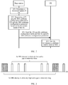
- FIG. 3 is a schematic diagram of resource configuration of SRSs having different densities.
- a low-density SRS may be used to obtain an effective channel, or may be used by UE whose movement speed is lower than a preset threshold to obtain complete channel information
- a high-density SRS may be used by UE whose movement speed is higher than the preset threshold to obtain complete channel information.
- the base station may determine one or more UE-specific SRS subframe configuration parameters in the UE-specific subframe configuration table.
- the base station may send the determined one or more UE-specific SRS subframe configuration parameters to the UE.
- the UE may select at least one SRS subframe configuration parameter from the received one or more UE-specific SRS subframe configuration parameters, and send an SRS in a subframe indicated by the SRS subframe configuration parameter.
- the UE determines, based on the received UE-specific SRS subframe configuration parameter and the received identification information of the UE-specific SRS subframe configuration table, a subframe used to send an SRS.
- the UE finds, from a preconfigured plurality of UE-specific SRS subframe configuration tables based on the identification information of the UE-specific SRS subframe configuration table, the UE-specific SRS subframe configuration table allocated by the base station, and determines, in the UE-specific SRS subframe configuration table based on the UE-specific SRS subframe configuration parameter, a subframe used to send an SRS.
- the UE-specific SRS subframe configuration parameter is a periodic SRS subframe configuration parameter
- the UE may periodically send an SRS in a specified subframe used to send an SRS.
- the UE-specific SRS subframe configuration parameter is an aperiodic SRS subframe configuration parameter
- the UE after receiving trigger information delivered by the base station, the UE sends an SRS in a specified subframe used to send an SRS.
- the method 200 may further include: 201': The base station determines movement speeds of all UEs in a cell.
- step 201' because the movement speeds of all the UEs in the cell includes the movement speed of the UE, step 201 may not be performed.
- the base station determines the used cell-specific SRS subframe configuration table in a plurality of cell-specific SRS subframe configuration tables based on the movement speeds of all the UEs in the cell, and determines a cell-specific SRS subframe configuration parameter in the determined cell-specific SRS subframe configuration table, where the cell-specific SRS subframe configuration parameter is used to indicate a subframe set used to send an SRS in the cell.
- the currently used cell-specific SRS subframe configuration table may be determined in step 202', and step 202' is performed before step 202.
- the base station may determine the used cell-specific SRS subframe configuration table in the plurality of cell-specific SRS subframe configuration tables based on an average movement speed of all the UEs in the cell.
- the base station sends the cell-specific SRS subframe configuration parameter and identification information of the used cell-specific SRS subframe configuration set to the UE.
- the cell-specific SRS subframe configuration parameter and the identification information of the cell-specific SRS subframe configuration table may be carried in a same configuration field.
- the step 203' includes: sending, by the base station, a message to the UE, where a field of the message carries the cell-specific SRS subframe configuration parameter and the identification information of the cell-specific SRS subframe configuration table.
- identification information with a particular length may be added to a cell-specific SRS subframe configuration field stipulated in an existing protocol, to indicate the cell-specific SRS subframe configuration table.
- the cell-specific SRS subframe configuration parameter and the identification information of the cell-specific SRS subframe configuration table may be carried in a field srs-SubframeConfig.
- a new cell SRS subframe configuration field such as srs-SubframeConfig-BF may be alternatively defined.
- the cell-specific SRS subframe configuration parameter and the identification information of the cell-specific SRS subframe configuration table may be carried in the field srs-SubframeConfig-BF.
- Srs-SubframeConfig or srs-SubframeConfig-BF may be delivered to the UE by using a system information block (System Information Block, SIB) 2.
- SIB System Information Block
- cell-specific SRS subframe configuration parameter and the identification information of the cell-specific SRS subframe configuration table may alternatively be carried in different configuration fields. This is not limited in this embodiment of the present invention.
- the cell-specific SRS subframe configuration parameter is carried in a field srs-SubframeConfig sent by the base station to the UE, which is the same as the prior art.
- the identification information of the cell-specific SRS subframe configuration table may not be sent by default, or may be sent to the UE by using another field or information element.
- steps 203 and 203' may be simultaneously performed, or may be non-simultaneously performed. This is not limited in this embodiment of the present invention.
- the base station may simultaneously send cell-specific SRS configuration information and UE-specific SRS configuration information to the UE, or may send only the UE-specific SRS configuration information to the UE. For example, within a particular time after the base station sends the cell-specific SRS configuration information to the UE, when the base station configures an SRS resource for the UE again, the base station may send only the UE-specific SRS configuration information to the UE.
- the UE determines, based on the cell-specific SRS subframe configuration parameter and the identification information of the used cell-specific SRS subframe configuration set sent by the base station, a subframe set used to send an SRS in the cell.
- PUSCH Physical Uplink Shared Channel
- the method 200 may further include: sending, by the base station, a quantity L 1 to the UE, where L 1 is a maximum quantity of symbols that are in a subframe and that are used to send an SRS, and L 1 is a positive integer greater than 1.
- indication information about L 1 may be added to the existing cell-specific SRS subframe configuration parameter field srs-SubframeConfig.
- the indication information about L 1 may be added to the existing UE-specific SRS subframe configuration parameter fields srs-ConfigIndex and srs-ConfigIndexAp-r10.
- this embodiment of the present invention is not limited thereto, and a new cell-specific SRS subframe configuration parameter field (for example, a field srs-SubframeConfig-BF ) or a new UE-specific SRS subframe configuration parameter field (for example, a field srs-ConfigIndex-Prebf ) may be alternatively defined.
- the cell-specific SRS subframe configuration parameter field or the UE-specific SRS subframe configuration parameter field carries the indication information about L 1 .
- a location of a symbol that is in a subframe and that is used to send an SRS may be preconfigured in the base station and the UE, or may be agreed on by the base station and the UE in advance.
- locations of L 1 symbols that are in a subframe and that are used to send an SRS may be concentrated on the last L 1 symbols in the subframe.
- the UE can be prevented from transmitting a PUSCH on a symbol of a subframe that may be used by another UE in the cell to send an SRS.
- the method 200 may further include: sending, by the base station, indication information to the UE.
- the indication information is used to instruct the UE to send L 2 SRSs after the aperiodic SRS is triggered.
- the indication information may be used to instruct the UE to send the L 2 SRSs in each period.
- L 2 is a positive integer greater than 1 and less than or equal to L 1 .
- the UE may send L 2 aperiodic SRSs based on the received indication information after receiving triggering of an aperiodic SRS, or send L 2 periodic SRSs in each period.
- the indication information sent by the base station is further used to indicate a manner used to send the L 2 SRSs.
- the UE sends the L 2 SRSs based on the manner indicated by the indication information.
- the base station may notify the UE of a quantity of SRSs sent after the aperiodic SRS is triggered, or a quantity of SRSs sent in each period.
- the base station and the UE may further predetermine the quantity of SRSs sent by the UE after the aperiodic SRS is triggered, or the quantity L 2 of SRSs sent by the UE in each period.
- the quantity L 2 is equal to L 1 .
- the base station needs to send only the indication information to the UE, to indicate a manner used to send an SRS. That is, the method 200 may further include: sending the indication information to the UE, where the indication information is used to indicate a manner used by the UE to send the L 2 SRSs after an aperiodic SRS is triggered, or is used to indicate a manner used by the UE to send the L 2 SRSs in each period.
- the manner used to send the L 2 SRSs may be determined by the base station based on the movement speed of the UE.
- the base station may instruct, based on the movement speed of the UE, the UE to send the L 2 SRSs by using the plurality of different manners.
- the base station may preconfigure a correspondence between the movement speed of the UE and an SRS sending manner.
- the manner includes: sending the L 2 SRSs in one subframe indicated by the UE-specific SRS subframe configuration parameter.
- the L 2 SRSs may be continuously sent on the last L 2 symbols of the subframe.
- an uplink subframe may be configured in the UE-specific SRS subframe configuration table to send an SRS, to further increase a density of sending an SRS by the UE, and to be applied to a high-speed movement scenario of the UE.
- subframe offsets 1 and 6 correspond to special subframes.
- the UE-specific SRS subframe configuration tables shown in Table 8 and Table 16 do not include configurations whose SRS subframe offsets are 1 and 6. Therefore, if Table 8 and Table 16 are used for SRS configuration in this scenario, the UE may send more than two SRSs in one uplink subframe. This helps the base station obtain complete channel information in a high-speed movement scenario of the UE.
- Table 8 may be used for subframe configuration of a periodic SRS
- Table 16 may be used for subframe configuration of an aperiodic SRS. It should be understood that this is used only as an example for description, and is not limited in this embodiment of the present invention.
- the manner includes: sending the L 2 SRSs in a plurality of subframes starting from a subframe indicated by the UE-specific SRS subframe configuration parameter.
- Table 9 may be used for subframe configuration of a periodic SRS
- Table 3 may be used for subframe configuration of an aperiodic SRS.
- this is used only as an example for description, and is not limited in this embodiment of the present invention.
- a value of N is related to the movement speed of the UE, and a higher movement speed of the UE indicates a smaller value of N.
- Information whose length may be two bits (bit) may be used to indicate the manner used to send the L 2 SRSs, as shown in Table 17. It should be understood that based on a combination of values of N and L 2 , information having another length may alternatively be used to indicate the manner used to send the L 2 SRSs.
- L 2 SRSs are continuously sent in one subframe 01
- the base station may instruct the UE to continuously send four SRSs in one subframe satisfying a condition.
- the base station may instruct the UE to continuously send two SRSs in each of two subframes satisfying a condition.
- the base station may instruct the UE to send one SRS in each of four subframes satisfying a condition.
- FIG. 5 is a schematic structural diagram of a base station 500 according to an embodiment of the present invention.
- the base station 500 is configured to perform the method performed by the base station in the method 200 shown in FIG. 2 .
- the base station 500 may include a determining unit 510 and a sending unit 520.
- the determining unit 510 is configured to: determine a movement speed of user equipment UE, determine, based on the movement speed of the UE, a UE-specific subframe configuration set in a plurality of UE-specific SRS subframe configuration sets corresponding to a used cell-specific SRS subframe configuration set, and determine a UE-specific SRS subframe configuration parameter in the determined UE-specific subframe configuration set, where the UE-specific SRS subframe configuration parameter is used to indicate a subframe used to send an SRS.
- the sending unit 520 is configured to send the UE-specific SRS subframe configuration parameter and identification information of the UE-specific subframe configuration set determined by the determining unit to the UE.
- the UE-specific SRS subframe configuration set allocated to the UE is determined in a plurality of UE-specific SRS subframe configuration sets based on the movement speed of the UE, and the UE-specific SRS subframe configuration parameter is determined in the UE-specific SRS subframe configuration set, so that a density of sending an SRS by the UE can be adaptively adjusted based on the movement speed of the UE, to help the base station obtain complete channel information. In addition, SRS resource waste can be avoided.
- the UE 500 may further include a receiving unit, configured to receive an SRS and another uplink signal sent by an UE.
- the determining unit 510 is further configured to: determine movement speeds of all UEs in a cell, determine the used cell-specific SRS subframe configuration set in a plurality of cell-specific SRS subframe configuration sets based on the movement speeds of all the UEs in the cell, and determine a cell-specific SRS subframe configuration parameter in the cell-specific SRS subframe configuration set, where the cell-specific SRS subframe configuration parameter is used to indicate a subframe set used to send an SRS in the cell.
- the sending unit 520 is further configured to send identifiers of the cell-specific SRS subframe configuration parameter and the cell-specific SRS subframe configuration set determined by the determining unit to the UE.
- the sending unit 520 is further configured to send a quantity L 1 to the UE, where L 1 is a maximum quantity of symbols that are in a subframe and that are used to send an SRS, and L 1 is a positive integer greater than 1.
- the sending unit 520 is further configured to send indication information to the UE, where the indication information is used to instruct the UE to send L 2 SRSs after triggering an aperiodic SRS, or is used to instruct the UE to send L 2 SRSs in each period.
- the indication information is further used to indicate a manner used to send the L 2 SRSs, where L 2 is a positive integer greater than 1 and less than or equal to L 1 .
- the sending unit 520 is further configured to send the indication information to the UE, where the indication information is used to indicate a manner used by the UE to send the L 2 SRSs after an aperiodic SRS is triggered, or is used to indicate a manner used by the UE to send the L 2 SRSs in each period, and L 2 is a positive integer greater than 1 and less than or equal to L 1 .
- the manner includes: sending the L 2 SRSs in one subframe indicated by the UE-specific SRS subframe configuration parameter.
- the manner includes: sending the L 2 SRSs in a plurality of subframes starting from a subframe indicated by the UE-specific SRS subframe configuration parameter.
- the determining unit 510 may be implemented by a processor, and the sending unit may be implemented by a transmitter.
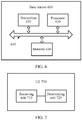
- the base station 600 may include a processor 610, a transmitter 620, a memory 630, and a bus system 640, and the processor 610, the transmitter 620, and the memory 630 are connected by using the bus system 640.
- the memory 630 may be configured to store code executed by the processor 610 and the like.
- the bus system 640 further includes a power supply bus, a control bus, and a status signal bus in addition to a data bus.
- the base station 600 may further include a receiver, configured to receive an SRS and another uplink signal sent by an UE.
- the base station 500 shown in FIG. 5 and the base station 600 shown in FIG. 6 can implement various processes implemented by the base station in the foregoing method embodiment, and to avoid repetition, details are not described herein again.
- the processor may be an integrated circuit chip and has a signal processing capability.
- steps in the foregoing method embodiments can be implemented by using a hardware integrated logical circuit in the processor, or by using instructions in a form of software.
- the processor may be a general purpose processor, a digital signal processor (Digital Signal Processor, DSP), an application-specific integrated circuit (Application Specific Integrated Circuit, ASIC), a field programmable gate array (Field Programmable Gate Array, FPGA) or another programmable logical device, a discrete gate or transistor logic device, or a discrete hardware component.
- DSP Digital Signal Processor
- ASIC Application Specific Integrated Circuit
- FPGA Field Programmable Gate Array
- the general purpose processor may be a microprocessor, or the processor may be any conventional processor or the like. Steps of the methods disclosed with reference to the embodiments of the present invention may be directly executed and accomplished by means of a hardware decoding processor, or may be executed and accomplished by using a combination of hardware and software modules in the decoding processor.
- a software module may be located in a mature storage medium in the art, such as a random access memory, a flash memory, a read-only memory, a programmable read-only memory, an electrically erasable programmable memory, a register, or the like. The storage medium is located in the memory, and a processor reads information in the memory and completes the steps in the foregoing methods in combination with hardware of the processor.
- the memory in the embodiments of the present invention may be a volatile memory or a nonvolatile memory, or may include a volatile memory and a nonvolatile memory.
- the nonvolatile memory may be a read-only memory (Read-Only Memory, ROM), a programmable read-only memory (Programmable ROM, PROM), an erasable programmable read-only memory (Erasable PROM, EPROM), an electrically erasable programmable read-only memory (Electrically EPROM, EEPROM), or a flash memory.
- the volatile memory may be a random access memory (Random Access Memory, RAM), used as an external cache.
- RAMs may be used, for example, a static random access memory (Static RAM, SRAM), a dynamic random access memory (Dynamic RAM, DRAM), a synchronous dynamic random access memory (Synchronous DRAM, SDRAM), a double data rate synchronous dynamic random access memory (Double Data Rate SDRAM, DDR SDRAM), an enhanced synchronous dynamic random access memory (Enhanced SDRAM, ESDRAM), a synchronous link dynamic random access memory (Synchlink DRAM, SLDRAM), and a direct rambus random access memory (Direct Rambus RAM, DR RAM).
- Static RAM static random access memory
- DRAM dynamic random access memory
- DRAM synchronous dynamic random access memory
- SDRAM double data rate synchronous dynamic random access memory
- Enhanced SDRAM, ESDRAM enhanced synchronous dynamic random access memory
- Synchlink DRAM synchronous link dynamic random access memory
- DR RAM direct rambus random access memory
- FIG. 7 is a schematic structural diagram of UE 700 according to an embodiment of the present invention. As shown in FIG. 7 , the UE 700 includes a receiving unit 710 and a determining unit 720.
- the receiving unit 710 is configured to receive identifiers of a UE-specific SRS subframe configuration parameter and a UE-specific subframe configuration set to which the UE-specific SRS subframe configuration parameter belongs, where the identifiers are sent by a base station, and the UE-specific subframe configuration set is determined by the base station based on a movement speed of the UE in a plurality of UE-specific subframe configuration sets corresponding to a used cell-specific SRS subframe configuration set.
- the determining unit 720 is configured to determine, based on the identifiers of the UE-specific SRS subframe configuration parameter and the UE-specific subframe configuration set received by the receiving unit, a subframe used to send an SRS.
- the identifier of the UE-specific SRS subframe configuration set determined by the base station based on the movement speed of the UE and the UE-specific SRS subframe configuration parameter are received, and the subframe used to send an SRS is determined based on the two, so that the sent SRS can satisfy an SRS requirement when the base station obtains complete channel information.
- the UE 700 may further include a sending unit, configured to send an SRS and another uplink signal.
- a sending unit configured to send an SRS and another uplink signal.
- the receiving unit 710 is further configured to receive identifiers of a cell-specific SRS subframe configuration parameter and the cell-specific SRS subframe configuration set to which the cell-specific SRS subframe configuration parameter belongs, where the identifiers are sent by the base station, and the cell-specific SRS subframe configuration set is determined by the base station in a plurality of cell-specific SRS subframe configuration sets based on movement speeds of all UEs in a cell.
- the determining unit 720 is further configured to determine, based on the identifiers of the cell-specific SRS subframe configuration parameter and the cell-specific SRS subframe configuration sets received by the receiving unit, a subframe set used to send an SRS in the cell.
- the identifier of the used cell-specific SRS subframe configuration set determined by the base station based on the movement speeds of all the UEs in the cell and the cell-specific SRS subframe configuration parameter are received, and the subframe set used to send an SRS in the cell is determined based on the two. Therefore, subframe sets in which UE may send an SRS can be determined, to avoid transmitting a physical uplink shared channel PUSCH in a subframe that may be used by another UE in the cell to send an SRS.
- the receiving unit 710 is further configured to receive a quantity L 1 sent by the base station, where L 1 is a maximum quantity of symbols that are in a subframe and that are used to send an SRS, and L 1 is a positive integer greater than 1.
- the receiving unit 710 is further configured to receive indication information sent by the base station, where the indication information is used to instruct the UE to send L 2 SRSs after triggering an aperiodic SRS, or the indication information is used to instruct the UE to send L 2 SRSs in each period, and L 2 is a positive integer greater than 1 and less than or equal to L 1 .
- the indication information is further used to indicate a manner used to send the L 2 SRSs.
- the manner includes: sending the L 2 SRSs in one subframe indicated by the UE-specific SRS subframe configuration parameter.
- the manner includes: sending the L 2 SRSs in a plurality of subframes starting from a subframe indicated by the UE-specific SRS subframe configuration parameter.
- the receiving unit 710 may be implemented by a receiver
- the determining unit 720 may be implemented by a processor.
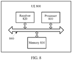
- the UE 800 may include a processor 810, a receiver 820, a memory 830, and a bus system 840, and the processor 810, the receiver 820, and the memory 830 are connected by using the bus system 840.
- the memory 830 may be configured to store code executed by the processor 810 and the like.
- the bus system 840 further includes a power supply bus, a control bus, and a status signal bus in addition to a data bus.
- the UE 800 may further include a transmitter, configured to send an SRS and another uplink signal.
- the UE 700 shown in FIG. 7 and the UE 800 shown in FIG. 8 can implement various processes implemented by the UE in the foregoing method embodiment, and to avoid repetition, details are not described herein again.
- the processor may be an integrated circuit chip and has a signal processing capability.
- steps in the foregoing method embodiments can be implemented by using a hardware integrated logical circuit in the processor, or by using instructions in a form of software.
- the processor may be a general-purpose processor, a DSP, an ASIC, an FPGA, another programmable logical device, a discrete gate or transistor logic device, or a discrete hardware component. It may implement or perform the methods, the steps, and logical block diagrams that are disclosed in the embodiments of the present invention.
- the general purpose processor may be a microprocessor, or the processor may be any conventional processor or the like.
- Steps of the methods disclosed with reference to the embodiments of the present invention may be directly executed and accomplished by means of a hardware decoding processor, or may be executed and accomplished by using a combination of hardware and software modules in the decoding processor.
- a software module may be located in a mature storage medium in the art, such as a random access memory, a flash memory, a read-only memory, a programmable read-only memory, an electrically erasable programmable memory, a register, or the like.
- the storage medium is located in the memory, and a processor reads information in the memory and completes the steps in the foregoing methods in combination with hardware of the processor.
- the memory in the embodiments of the present invention may be a volatile memory or a nonvolatile memory, or may include a volatile memory and a nonvolatile memory.
- the non-volatile memory may be a ROM, a PROM, an EPROM, an EEPROM, or a flash memory.
- the volatile memory may be a RAM, and is used as an external cache.
- RAMs for example, an SRAM, a DRAM, an SDRAM, a DDR SDRAM, an ESDRAM, an SLDRAM, and a DR RAM can be used. This is used only as an example, but is not intended for limitative descriptions. It should be noted that the memory of the systems and methods described in this specification is intended to include, but is not limited to, these and any memory of another proper type.
- the disclosed system, apparatus, and method may be implemented in other manners.
- the described apparatus embodiment is merely an example.
- the unit division is merely logical function division and may be other division in actual implementation.
- a plurality of units or components may be combined or integrated into another system, or some features may be ignored or not performed.
- the displayed or discussed mutual couplings or direct couplings or communication connections may be implemented by using some interfaces.
- the indirect couplings or communication connections between the apparatuses or units may be implemented in electronic, mechanical, or other forms.
- the units described as separate parts may or may not be physically separate, and parts displayed as units may or may not be physical units, may be located in one position, or may be distributed on a plurality of network units. Some or all of the units may be selected based on actual requirements to achieve the objectives of the solutions of the embodiments.
- the functions When functions are implemented in the form of a software functional unit and sold or used as an independent product, the functions may be stored in a computer-readable storage medium. Based on such an understanding, the technical solutions of this application essentially, or the part contributing to the prior art, or some of the technical solutions may be implemented in a form of a software product.
- the computer software product is stored in a storage medium, and includes several instructions for instructing a computer device (which may be a personal computer, a server, a network device, or the like) to perform all or some of the steps of the methods described in the embodiments of this application.
- the foregoing storage medium includes: any medium that can store program code, such as a USB flash drive, a removable hard disk, a read-only memory (Read-Only Memory, ROM), a random access memory (Random Access Memory, RAM), a magnetic disk, or an optical disc.
- program code such as a USB flash drive, a removable hard disk, a read-only memory (Read-Only Memory, ROM), a random access memory (Random Access Memory, RAM), a magnetic disk, or an optical disc.
Landscapes
- Engineering & Computer Science (AREA)
- Signal Processing (AREA)
- Computer Networks & Wireless Communication (AREA)
- Mobile Radio Communication Systems (AREA)
- Quality & Reliability (AREA)
- Physics & Mathematics (AREA)
- Electromagnetism (AREA)
Claims (13)
- Konfigurationsverfahren für ein klingendes Referenzsignal, SRS, das Folgendes umfasst:Bestimmen (201), durch eine Basisstation, einer Bewegungsgeschwindigkeit des Benutzergeräts, UE;Bestimmen (202), durch die Basisstation auf der Grundlage der Bewegungsgeschwindigkeit des UE, eines UE-spezifischen SRS-Unterrahmen-Konfigurationssatzes in mehreren UE-spezifischen SRS-Unterrahmen-Konfigurationssätzen, die einem verwendeten zellspezifischen SRS-Unterrahmen-Konfigurationssatz entsprechen, und Bestimmen eines UE-spezifischen SRS-Unterrahmen-Konfigurationsparameters in dem bestimmten UE-spezifischen Unterrahmen-Konfigurationssatz, wobei der UE-spezifische SRS-Unterrahmen-Konfigurationsparameter verwendet wird, um einen Unterrahmen anzuzeigen, der zum Senden eines SRS verwendet wird; undSenden (203), durch die Basisstation, des UE-spezifischen SRS-Unterrahmen-Konfigurationsparameters und der Identifikationsinformationen des UE-spezifischen Unterrahmen-Konfigurationssatzes an das UE, wobei das Verfahren ferner Folgendes umfasst:
Senden, durch die Basisstation, einer Menge L1 an das UE, wobei L1 eine maximale Menge von Symbolen ist, die in einem Unterrahmen sind und die zum Senden eines SRS verwendet werden, und L1 eine positive ganze Zahl größer als 1 ist. - Verfahren nach Anspruch 1, ferner Folgendes umfassend:
Senden, durch die Basisstation, von Anzeigeinformationen an das UE, wobei die Anzeigeinformationen verwendet werden, um eine Art und Weise anzuzeigen, die vom UE verwendet wird, um L2 SRS zu senden, nachdem ein aperiodisches SRS ausgelöst wurde, oder verwendet werden, um eine Art und Weise anzugeben, die vom EU verwendet wird, um L2 SRS in jeder Periode zu senden, wobei L2 eine positive ganze Zahl größer als 1 und kleiner oder gleich L1 ist, und L1 eine maximale Menge von Symbolen ist, die in einem Unterrahmen sind und die zum Senden eines SRS verwendet werden. - Verfahren nach Anspruch 2, wobei die Art und Weise Folgendes umfasst:Senden der L2 SRS in einem Unterrahmen, der durch den UE-spezifischen SRS-Unterrahmen-Konfigurationsparameter angezeigt wird.
- Verfahren nach Anspruch 2, wobei die Art und Weise Folgendes umfasst:
Senden der L2 SRS in mehreren Unterrahmen, ausgehend von einem Unterrahmen, der durch den UE-spezifischen SRS-Unterrahmen-Konfigurationsparameter angezeigt wird. - Basisstation, die Folgendes umfasst:
eine Bestimmungseinheit (510), die dafür konfiguriert ist, eine Bewegungsgeschwindigkeit des Benutzergeräts, UE, zu bestimmen, wobei die Bestimmungseinheit (510) ferner für Folgendes konfiguriert ist:auf der Grundlage der Bewegungsgeschwindigkeit des UE einen UE-spezifischen SRS-Unterrahmen-Konfigurationssatz in mehreren UE-spezifischen SRS-Unterrahmen-Konfigurationssätzen zu bestimmen, die einem verwendeten zellenspezifischen SRS-Unterrahmen-Konfigurationssatz entsprechen, und einen UE-spezifischen SRS-Unterrahmen-Konfigurationsparameter in dem bestimmten UE-spezifischen Unterrahmen-Konfigurationssatz zu bestimmen, wobei der UE-spezifische SRS-Unterrahmen-Konfigurationsparameter verwendet wird, um einen Unterrahmen anzuzeigen, der zum Senden eines SRS verwendet wird; undeine Sendeeinheit (520), die dafür konfiguriert ist, den UE-spezifischen SRS-Unterrahmen-Konfigurationsparameter und Identifikationsinformationen des UE-spezifischen Unterrahmen-Konfigurationssatzes, der durch die Bestimmungseinheit (510) bestimmt wird, an das UE zu senden, wobei die Sendeeinheit ferner dafür konfiguriert ist, eine Menge L1 an das UE zu senden, wobei L1 eine maximale Menge von Symbolen ist, die in einem Unterrahmen sind und die verwendet werden, um ein SRS zu senden, und L1 eine positive ganze Zahl größer als 1 ist. - Basisstation nach Anspruch 5, wobei die Sendeeinheit ferner dafür konfiguriert ist, Anzeigeinformationen an das UE zu senden, wobei die Anzeigeinformationen verwendet werden, um eine Art und Weise anzuzeigen, die vom UE verwendet wird, um L2 SRS zu senden, nachdem ein aperiodisches SRS ausgelöst wurde, oder verwendet werden, um eine Art und Weise anzuzeigen, die vom UE verwendet wird, um L2 SRS in jeder Periode zu senden, wobei L2 eine positive ganze Zahl größer als 1 und kleiner oder gleich L1 ist, und L1 eine maximale Menge von Symbolen ist, die in einem Unterrahmen sind und die zum Senden eines SRS verwendet werden.
- Basisstation nach Anspruch 6, wobei die Art und Weise Folgendes umfasst:
Senden der L2 SRS in einem Unterrahmen, der durch den UE-spezifischen SRS-Unterrahmen-Konfigurationsparameter angezeigt wird. - Basisstation nach Anspruch 6, wobei die Art und Weise Folgendes umfasst:
Senden der L2 SRS in mehreren Unterrahmen, ausgehend von einem Unterrahmen, der durch den UE-spezifischen SRS-Unterrahmen-Konfigurationsparameter angezeigt wird. - System, das die Basisstation nach einem der Ansprüche 5 bis 8 und das Benutzergerät, UE, und das Folgende umfasst:eine Empfangseinheit (710), die dafür konfiguriert ist, Identifikatoren eines Unterrahmen-Konfigurationsparameters eines UE-spezifischen klingenden Referenzsignals, SRS, und eines UE-spezifischen SRS-Unterrahmen-Konfigurationssatzes zu empfangen, zu dem der UE-spezifische SRS-Unterrahmen-Konfigurationsparameter gehört, wobei die Identifikatoren von einer Basisstation gesendet werden und der UE-spezifische Unterrahmen-Konfigurationssatz von der Basisstation auf der Grundlage einer Bewegungsgeschwindigkeit der UE in mehreren UE-spezifischen Unterrahmen-Konfigurationssätzen, die einem verwendeten zellspezifischen SRS-Unterrahmen-Konfigurationssatz entsprechen, bestimmt wird; undeine Bestimmungseinheit (720), die dafür konfiguriert ist, auf der Grundlage der Identifikatoren des UE-spezifischen SRS-Unterrahmen-Konfigurationsparameters und des UE-spezifischen Unterrahmen-Konfigurationssatzes, der von der Empfangseinheit (710) empfangen wird, einen Unterrahmen zu bestimmen, der zum Senden eines SRS verwendet wird.
- System nach Anspruch 9, wobei die Empfangseinheit ferner dafür konfiguriert ist, eine Menge L1 zu empfangen, die von der Basisstation gesendet wird, wobei L1 eine maximale Menge von Symbolen ist, die in einem Unterrahmen sind und die zum Senden eines SRS verwendet werden, und wobei L1 eine positive ganze Zahl größer als 1 ist.
- System nach Anspruch 9 oder 10, wobei die Empfangseinheit ferner dafür konfiguriert ist, von der Basisstation gesendete Anzeigeinformationen zu empfangen, wobei die Anzeigeinformationen dazu verwendet werden, eine vom UE zum Senden von L2 SRS nach Auslösen eines aperiodischen SRS verwendete Art und Weise anzuzeigen, oder verwendet werden, um eine Art und Weise anzuzeigen, die vom UE verwendet wird, um L2 SRS in jeder Periode zu senden, wobei L2 eine positive ganze Zahl größer als 1 und kleiner oder gleich L1 ist, und L1 eine maximale Menge von Symbolen ist, die in einem Unterrahmen sind und die zum Senden eines SRS verwendet werden.
- System nach Anspruch 11, wobei die Art und Weise Folgendes umfasst:
Senden der L2 SRS in einem Unterrahmen, der durch den UE-spezifischen SRS-Unterrahmen-Konfigurationsparameter angezeigt wird. - System nach Anspruch 11, wobei die Art und Weise Folgendes umfasst:
Senden der L2 SRS in mehreren Unterrahmen, ausgehend von einem Unterrahmen, der durch den UE-spezifischen SRS-Unterrahmen-Konfigurationsparameter angezeigt wird.
Applications Claiming Priority (2)
| Application Number | Priority Date | Filing Date | Title |
|---|---|---|---|
| CN201610293651.3A CN107347005B (zh) | 2016-05-05 | 2016-05-05 | 配置探测参考信号的方法和装置 |
| PCT/CN2017/082875 WO2017190659A1 (zh) | 2016-05-05 | 2017-05-03 | 配置探测参考信号的方法和装置 |
Publications (3)
| Publication Number | Publication Date |
|---|---|
| EP3444973A1 EP3444973A1 (de) | 2019-02-20 |
| EP3444973A4 EP3444973A4 (de) | 2019-03-27 |
| EP3444973B1 true EP3444973B1 (de) | 2020-08-12 |
Family
ID=60202758
Family Applications (1)
| Application Number | Title | Priority Date | Filing Date |
|---|---|---|---|
| EP17792485.9A Active EP3444973B1 (de) | 2016-05-05 | 2017-05-03 | Verfahren und vorrichtung zur konfigurierung eines sounding-referenzsignals |
Country Status (4)
| Country | Link |
|---|---|
| US (1) | US10819484B2 (de) |
| EP (1) | EP3444973B1 (de) |
| CN (1) | CN107347005B (de) |
| WO (1) | WO2017190659A1 (de) |
Families Citing this family (18)
| Publication number | Priority date | Publication date | Assignee | Title |
|---|---|---|---|---|
| CN109802810B (zh) * | 2017-11-17 | 2021-07-09 | 华为技术有限公司 | 发送探测参考信号srs的方法和装置 |
| CN108696346B (zh) | 2017-11-25 | 2019-07-12 | 华为技术有限公司 | 一种参考信号的配置方法和装置 |
| EP3796708B1 (de) | 2018-06-22 | 2023-06-21 | Huawei Technologies Co., Ltd. | Verfahren und vorrichtung zum lastausgleich |
| CN113439410B (zh) * | 2019-02-15 | 2025-01-07 | 苹果公司 | 用于动态配置用户装备探测参考信号(srs)资源的系统和方法 |
| US11245552B2 (en) | 2019-03-29 | 2022-02-08 | Skyworks Solutions, Inc. | Sounding reference signal switching |
| CN110213828B (zh) * | 2019-05-29 | 2022-02-01 | 维沃移动通信有限公司 | Srs的发送方法及移动终端 |
| US12132557B2 (en) | 2019-07-05 | 2024-10-29 | Telefonaktiebolaget Lm Ericsson (Publ) | Method and network device for signal resource configuration |
| CN112312300B (zh) * | 2019-07-25 | 2026-04-10 | 中兴通讯股份有限公司 | 通信管理、速度上报方法、装置、基站、终端及存储介质 |
| US11251849B2 (en) * | 2019-08-16 | 2022-02-15 | Qualcomm Incorporated | Iterative multi-beam selection with uplink-downlink beam training |
| KR102182810B1 (ko) * | 2019-10-16 | 2020-11-25 | 한국과학기술원 | Ofdm 기반의 광대역 다중 안테나 시스템에서 하이브리드 송수신기 동시 설계 방법 |
| CN112788750B (zh) * | 2019-11-06 | 2023-09-29 | 大唐移动通信设备有限公司 | Srs传输方法、装置、网络设备、终端和存储介质 |
| WO2021134698A1 (zh) * | 2019-12-31 | 2021-07-08 | 华为技术有限公司 | 一种探测参考信号srs周期的配置方法及装置 |
| CN113225813B (zh) * | 2020-02-04 | 2023-02-03 | 华为技术服务有限公司 | 一种上行参考信号发射方式确定方法、装置及系统 |
| CN116709414A (zh) * | 2020-02-12 | 2023-09-05 | 北京小米移动软件有限公司 | 波束管理方法、装置、设备及存储介质 |
| CN113541899B (zh) * | 2020-04-21 | 2023-07-04 | 维沃移动通信有限公司 | Srs的频域参数更新方法和设备 |
| CN114501486B (zh) * | 2020-11-12 | 2023-08-15 | 中国移动通信集团浙江有限公司 | 高速移动场景下的小区参数配置方法、装置及计算设备 |
| US11956108B2 (en) | 2021-06-14 | 2024-04-09 | Skyworks Solutions, Inc. | Antenna swapping without blanking symbols |
| CN117882324A (zh) * | 2021-09-03 | 2024-04-12 | 瑞典爱立信有限公司 | 无线通信网络中的探测参考信号传输 |
Family Cites Families (11)
| Publication number | Priority date | Publication date | Assignee | Title |
|---|---|---|---|---|
| CN101960736B (zh) * | 2008-02-28 | 2013-07-31 | Lg电子株式会社 | 复用数据及控制信息的方法 |
| CN101572896B (zh) | 2008-04-29 | 2011-01-26 | 大唐移动通信设备有限公司 | 一种配置上行探测参考信号的方法和装置 |
| CN101447826B (zh) * | 2008-12-26 | 2012-10-03 | 华为技术有限公司 | 子帧分配方法、处理方法及装置 |
| CN101714897B (zh) * | 2009-11-12 | 2013-01-02 | 普天信息技术研究院有限公司 | 探测参考信号的配置方法 |
| CN102934382B (zh) | 2010-06-04 | 2016-08-10 | Lg电子株式会社 | 控制探测参考信号发送的上行发送功率的方法和用户设备 |
| CN103370898B (zh) * | 2011-02-07 | 2017-08-29 | 瑞典爱立信有限公司 | 用于探测参考信号srs的上行链路传送的基站(天线)选择的方法和装置 |
| CN103179666A (zh) * | 2011-12-23 | 2013-06-26 | 中兴通讯股份有限公司 | 一种测量参考信号资源分配方法和装置 |
| CN103002585A (zh) * | 2012-12-13 | 2013-03-27 | 电信科学技术研究院 | 一种小区srs资源分配方法和装置 |
| CN104956758B (zh) | 2013-01-10 | 2019-06-28 | 瑞典爱立信有限公司 | 双连通性模式的同时上行链路传输 |
| WO2014109686A1 (en) * | 2013-01-14 | 2014-07-17 | Telefonaktiebolaget L M Ericsson (Publ) | A user equipment, a network node and respective method therein for transmitting sounding reference signals |
| US11251893B2 (en) * | 2016-03-21 | 2022-02-15 | Qualcomm Incorporated | Supporting high speeds in vehicle-to-vehicle communication |
-
2016
- 2016-05-05 CN CN201610293651.3A patent/CN107347005B/zh active Active
-
2017
- 2017-05-03 EP EP17792485.9A patent/EP3444973B1/de active Active
- 2017-05-03 WO PCT/CN2017/082875 patent/WO2017190659A1/zh not_active Ceased
-
2018
- 2018-11-05 US US16/180,935 patent/US10819484B2/en active Active
Non-Patent Citations (1)
| Title |
|---|
| None * |
Also Published As
| Publication number | Publication date |
|---|---|
| CN107347005B (zh) | 2020-09-11 |
| EP3444973A1 (de) | 2019-02-20 |
| CN107347005A (zh) | 2017-11-14 |
| EP3444973A4 (de) | 2019-03-27 |
| US20190109689A1 (en) | 2019-04-11 |
| US10819484B2 (en) | 2020-10-27 |
| WO2017190659A1 (zh) | 2017-11-09 |
Similar Documents
| Publication | Publication Date | Title |
|---|---|---|
| EP3444973B1 (de) | Verfahren und vorrichtung zur konfigurierung eines sounding-referenzsignals | |
| US11368339B2 (en) | Sounding reference signal transmission method, network device and terminal device | |
| EP3713140B1 (de) | Verfahren zum versenden einer übertragungskonfigurationsindikation tci, netzseitige vorrichtung, und endgerätevorrichtung | |
| AU2020256361B2 (en) | Communications method, terminal device, network-side device, apparatus, and computer-readable storage medium | |
| AU2017440897B2 (en) | Signal transmission method, terminal device and network device | |
| EP3852444B1 (de) | Kanalmessverfahren, endgerätevorrichtung und netzwerkseitige vorrichtung | |
| EP3621392B1 (de) | Verfahren zur übertragung eines uplink-signals und endgerät | |
| WO2019127199A1 (zh) | 用于上行数据传输的方法和终端设备 | |
| EP3457735B1 (de) | Verfahren zur übertragung einer benutzersequenz, netzwerkvorrichtung und endgerätevorrichtung | |
| US10805909B2 (en) | Control signaling transmission method and apparatus | |
| CN108811075A (zh) | 通信方法、网络设备和终端设备 | |
| EP3720036A1 (de) | Drahtloskommunikationsverfahren und -vorrichtung | |
| EP3554188B1 (de) | Verfahren und vorrichtung zur konfigurierung von kommunikationsparametern | |
| EP4250846A1 (de) | Anzeigeverfahren, endgerätevorrichtung und funkzugangsnetzwerkvorrichtung | |
| WO2021253452A1 (en) | Method for transmitting control information | |
| EP3883319B1 (de) | Drahtloskommunikationsverfahren, endgerätevorrichtung und netzwerkvorrichtung | |
| EP3731591A1 (de) | Drahtloskommunikationsverfahren, endgerätevorrichtung und netzwerkvorrichtung | |
| EP3562233A1 (de) | Verfahren und vorrichtung zur übertragung von uplink-signalen | |
| EP3139669A1 (de) | Verfahren zur steuerung der leistung eines trägersignals, benutzergerät und basisstation | |
| EP3451552B1 (de) | Signalübertragungsverfahren und -vorrichtung | |
| WO2015043365A1 (zh) | 调度授权的控制方法、用户设备和网络设备 | |
| EP4380273A1 (de) | Informationsübertragungsverfahren und kommunikationsvorrichtung | |
| EP4561223A1 (de) | Informationsverarbeitungsverfahren und -vorrichtung sowie lesbares speichermedium | |
| EP3531770B1 (de) | Ressourcenkonfigurationsverfahren und -vorrichtung |
Legal Events
| Date | Code | Title | Description |
|---|---|---|---|
| STAA | Information on the status of an ep patent application or granted ep patent |
Free format text: STATUS: THE INTERNATIONAL PUBLICATION HAS BEEN MADE |
|
| PUAI | Public reference made under article 153(3) epc to a published international application that has entered the european phase |
Free format text: ORIGINAL CODE: 0009012 |
|
| STAA | Information on the status of an ep patent application or granted ep patent |
Free format text: STATUS: REQUEST FOR EXAMINATION WAS MADE |
|
| 17P | Request for examination filed |
Effective date: 20181115 |
|
| AK | Designated contracting states |
Kind code of ref document: A1 Designated state(s): AL AT BE BG CH CY CZ DE DK EE ES FI FR GB GR HR HU IE IS IT LI LT LU LV MC MK MT NL NO PL PT RO RS SE SI SK SM TR |
|
| AX | Request for extension of the european patent |
Extension state: BA ME |
|
| A4 | Supplementary search report drawn up and despatched |
Effective date: 20190225 |
|
| RIC1 | Information provided on ipc code assigned before grant |
Ipc: H04L 5/14 20060101ALI20190219BHEP Ipc: H04L 5/00 20060101ALI20190219BHEP Ipc: H04B 17/318 20150101AFI20190219BHEP |
|
| STAA | Information on the status of an ep patent application or granted ep patent |
Free format text: STATUS: EXAMINATION IS IN PROGRESS |
|
| DAV | Request for validation of the european patent (deleted) | ||
| DAX | Request for extension of the european patent (deleted) | ||
| 17Q | First examination report despatched |
Effective date: 20190809 |
|
| GRAP | Despatch of communication of intention to grant a patent |
Free format text: ORIGINAL CODE: EPIDOSNIGR1 |
|
| STAA | Information on the status of an ep patent application or granted ep patent |
Free format text: STATUS: GRANT OF PATENT IS INTENDED |
|
| GRAS | Grant fee paid |
Free format text: ORIGINAL CODE: EPIDOSNIGR3 |
|
| INTG | Intention to grant announced |
Effective date: 20200226 |
|
| GRAA | (expected) grant |
Free format text: ORIGINAL CODE: 0009210 |
|
| STAA | Information on the status of an ep patent application or granted ep patent |
Free format text: STATUS: THE PATENT HAS BEEN GRANTED |
|
| AK | Designated contracting states |
Kind code of ref document: B1 Designated state(s): AL AT BE BG CH CY CZ DE DK EE ES FI FR GB GR HR HU IE IS IT LI LT LU LV MC MK MT NL NO PL PT RO RS SE SI SK SM TR |
|
| REG | Reference to a national code |
Ref country code: CH Ref legal event code: EP |
|
| REG | Reference to a national code |
Ref country code: IE Ref legal event code: FG4D |
|
| REG | Reference to a national code |
Ref country code: DE Ref legal event code: R096 Ref document number: 602017021648 Country of ref document: DE |
|
| REG | Reference to a national code |
Ref country code: AT Ref legal event code: REF Ref document number: 1302592 Country of ref document: AT Kind code of ref document: T Effective date: 20200915 |
|
| REG | Reference to a national code |
Ref country code: LT Ref legal event code: MG4D |
|
| REG | Reference to a national code |
Ref country code: NL Ref legal event code: MP Effective date: 20200812 |
|
| PG25 | Lapsed in a contracting state [announced via postgrant information from national office to epo] |
Ref country code: NO Free format text: LAPSE BECAUSE OF FAILURE TO SUBMIT A TRANSLATION OF THE DESCRIPTION OR TO PAY THE FEE WITHIN THE PRESCRIBED TIME-LIMIT Effective date: 20201112 Ref country code: GR Free format text: LAPSE BECAUSE OF FAILURE TO SUBMIT A TRANSLATION OF THE DESCRIPTION OR TO PAY THE FEE WITHIN THE PRESCRIBED TIME-LIMIT Effective date: 20201113 Ref country code: SE Free format text: LAPSE BECAUSE OF FAILURE TO SUBMIT A TRANSLATION OF THE DESCRIPTION OR TO PAY THE FEE WITHIN THE PRESCRIBED TIME-LIMIT Effective date: 20200812 Ref country code: FI Free format text: LAPSE BECAUSE OF FAILURE TO SUBMIT A TRANSLATION OF THE DESCRIPTION OR TO PAY THE FEE WITHIN THE PRESCRIBED TIME-LIMIT Effective date: 20200812 Ref country code: HR Free format text: LAPSE BECAUSE OF FAILURE TO SUBMIT A TRANSLATION OF THE DESCRIPTION OR TO PAY THE FEE WITHIN THE PRESCRIBED TIME-LIMIT Effective date: 20200812 Ref country code: LT Free format text: LAPSE BECAUSE OF FAILURE TO SUBMIT A TRANSLATION OF THE DESCRIPTION OR TO PAY THE FEE WITHIN THE PRESCRIBED TIME-LIMIT Effective date: 20200812 Ref country code: BG Free format text: LAPSE BECAUSE OF FAILURE TO SUBMIT A TRANSLATION OF THE DESCRIPTION OR TO PAY THE FEE WITHIN THE PRESCRIBED TIME-LIMIT Effective date: 20201112 |
|
| REG | Reference to a national code |
Ref country code: AT Ref legal event code: MK05 Ref document number: 1302592 Country of ref document: AT Kind code of ref document: T Effective date: 20200812 |
|
| PG25 | Lapsed in a contracting state [announced via postgrant information from national office to epo] |
Ref country code: NL Free format text: LAPSE BECAUSE OF FAILURE TO SUBMIT A TRANSLATION OF THE DESCRIPTION OR TO PAY THE FEE WITHIN THE PRESCRIBED TIME-LIMIT Effective date: 20200812 Ref country code: PL Free format text: LAPSE BECAUSE OF FAILURE TO SUBMIT A TRANSLATION OF THE DESCRIPTION OR TO PAY THE FEE WITHIN THE PRESCRIBED TIME-LIMIT Effective date: 20200812 Ref country code: LV Free format text: LAPSE BECAUSE OF FAILURE TO SUBMIT A TRANSLATION OF THE DESCRIPTION OR TO PAY THE FEE WITHIN THE PRESCRIBED TIME-LIMIT Effective date: 20200812 Ref country code: RS Free format text: LAPSE BECAUSE OF FAILURE TO SUBMIT A TRANSLATION OF THE DESCRIPTION OR TO PAY THE FEE WITHIN THE PRESCRIBED TIME-LIMIT Effective date: 20200812 Ref country code: IS Free format text: LAPSE BECAUSE OF FAILURE TO SUBMIT A TRANSLATION OF THE DESCRIPTION OR TO PAY THE FEE WITHIN THE PRESCRIBED TIME-LIMIT Effective date: 20201212 |
|
| PG25 | Lapsed in a contracting state [announced via postgrant information from national office to epo] |
Ref country code: EE Free format text: LAPSE BECAUSE OF FAILURE TO SUBMIT A TRANSLATION OF THE DESCRIPTION OR TO PAY THE FEE WITHIN THE PRESCRIBED TIME-LIMIT Effective date: 20200812 Ref country code: RO Free format text: LAPSE BECAUSE OF FAILURE TO SUBMIT A TRANSLATION OF THE DESCRIPTION OR TO PAY THE FEE WITHIN THE PRESCRIBED TIME-LIMIT Effective date: 20200812 Ref country code: DK Free format text: LAPSE BECAUSE OF FAILURE TO SUBMIT A TRANSLATION OF THE DESCRIPTION OR TO PAY THE FEE WITHIN THE PRESCRIBED TIME-LIMIT Effective date: 20200812 Ref country code: CZ Free format text: LAPSE BECAUSE OF FAILURE TO SUBMIT A TRANSLATION OF THE DESCRIPTION OR TO PAY THE FEE WITHIN THE PRESCRIBED TIME-LIMIT Effective date: 20200812 Ref country code: SM Free format text: LAPSE BECAUSE OF FAILURE TO SUBMIT A TRANSLATION OF THE DESCRIPTION OR TO PAY THE FEE WITHIN THE PRESCRIBED TIME-LIMIT Effective date: 20200812 |
|
| REG | Reference to a national code |
Ref country code: DE Ref legal event code: R097 Ref document number: 602017021648 Country of ref document: DE |
|
| PG25 | Lapsed in a contracting state [announced via postgrant information from national office to epo] |
Ref country code: AL Free format text: LAPSE BECAUSE OF FAILURE TO SUBMIT A TRANSLATION OF THE DESCRIPTION OR TO PAY THE FEE WITHIN THE PRESCRIBED TIME-LIMIT Effective date: 20200812 Ref country code: AT Free format text: LAPSE BECAUSE OF FAILURE TO SUBMIT A TRANSLATION OF THE DESCRIPTION OR TO PAY THE FEE WITHIN THE PRESCRIBED TIME-LIMIT Effective date: 20200812 Ref country code: ES Free format text: LAPSE BECAUSE OF FAILURE TO SUBMIT A TRANSLATION OF THE DESCRIPTION OR TO PAY THE FEE WITHIN THE PRESCRIBED TIME-LIMIT Effective date: 20200812 |
|
| PLBE | No opposition filed within time limit |
Free format text: ORIGINAL CODE: 0009261 |
|
| STAA | Information on the status of an ep patent application or granted ep patent |
Free format text: STATUS: NO OPPOSITION FILED WITHIN TIME LIMIT |
|
| PG25 | Lapsed in a contracting state [announced via postgrant information from national office to epo] |
Ref country code: SK Free format text: LAPSE BECAUSE OF FAILURE TO SUBMIT A TRANSLATION OF THE DESCRIPTION OR TO PAY THE FEE WITHIN THE PRESCRIBED TIME-LIMIT Effective date: 20200812 |
|
| 26N | No opposition filed |
Effective date: 20210514 |
|
| PG25 | Lapsed in a contracting state [announced via postgrant information from national office to epo] |
Ref country code: IT Free format text: LAPSE BECAUSE OF FAILURE TO SUBMIT A TRANSLATION OF THE DESCRIPTION OR TO PAY THE FEE WITHIN THE PRESCRIBED TIME-LIMIT Effective date: 20200812 |
|
| PG25 | Lapsed in a contracting state [announced via postgrant information from national office to epo] |
Ref country code: SI Free format text: LAPSE BECAUSE OF FAILURE TO SUBMIT A TRANSLATION OF THE DESCRIPTION OR TO PAY THE FEE WITHIN THE PRESCRIBED TIME-LIMIT Effective date: 20200812 |
|
| REG | Reference to a national code |
Ref country code: CH Ref legal event code: PL |
|
| GBPC | Gb: european patent ceased through non-payment of renewal fee |
Effective date: 20210503 |
|
| PG25 | Lapsed in a contracting state [announced via postgrant information from national office to epo] |
Ref country code: CH Free format text: LAPSE BECAUSE OF NON-PAYMENT OF DUE FEES Effective date: 20210531 Ref country code: LU Free format text: LAPSE BECAUSE OF NON-PAYMENT OF DUE FEES Effective date: 20210503 Ref country code: MC Free format text: LAPSE BECAUSE OF FAILURE TO SUBMIT A TRANSLATION OF THE DESCRIPTION OR TO PAY THE FEE WITHIN THE PRESCRIBED TIME-LIMIT Effective date: 20200812 Ref country code: LI Free format text: LAPSE BECAUSE OF NON-PAYMENT OF DUE FEES Effective date: 20210531 |
|
| REG | Reference to a national code |
Ref country code: BE Ref legal event code: MM Effective date: 20210531 |
|
| PG25 | Lapsed in a contracting state [announced via postgrant information from national office to epo] |
Ref country code: IE Free format text: LAPSE BECAUSE OF NON-PAYMENT OF DUE FEES Effective date: 20210503 Ref country code: GB Free format text: LAPSE BECAUSE OF NON-PAYMENT OF DUE FEES Effective date: 20210503 |
|
| PG25 | Lapsed in a contracting state [announced via postgrant information from national office to epo] |
Ref country code: FR Free format text: LAPSE BECAUSE OF NON-PAYMENT OF DUE FEES Effective date: 20210531 |
|
| PG25 | Lapsed in a contracting state [announced via postgrant information from national office to epo] |
Ref country code: BE Free format text: LAPSE BECAUSE OF NON-PAYMENT OF DUE FEES Effective date: 20210531 |
|
| PG25 | Lapsed in a contracting state [announced via postgrant information from national office to epo] |
Ref country code: PT Free format text: LAPSE BECAUSE OF FAILURE TO SUBMIT A TRANSLATION OF THE DESCRIPTION OR TO PAY THE FEE WITHIN THE PRESCRIBED TIME-LIMIT Effective date: 20201214 |
|
| PG25 | Lapsed in a contracting state [announced via postgrant information from national office to epo] |
Ref country code: CY Free format text: LAPSE BECAUSE OF FAILURE TO SUBMIT A TRANSLATION OF THE DESCRIPTION OR TO PAY THE FEE WITHIN THE PRESCRIBED TIME-LIMIT Effective date: 20200812 |
|
| PG25 | Lapsed in a contracting state [announced via postgrant information from national office to epo] |
Ref country code: HU Free format text: LAPSE BECAUSE OF FAILURE TO SUBMIT A TRANSLATION OF THE DESCRIPTION OR TO PAY THE FEE WITHIN THE PRESCRIBED TIME-LIMIT; INVALID AB INITIO Effective date: 20170503 |
|
| PG25 | Lapsed in a contracting state [announced via postgrant information from national office to epo] |
Ref country code: MK Free format text: LAPSE BECAUSE OF FAILURE TO SUBMIT A TRANSLATION OF THE DESCRIPTION OR TO PAY THE FEE WITHIN THE PRESCRIBED TIME-LIMIT Effective date: 20200812 |
|
| PG25 | Lapsed in a contracting state [announced via postgrant information from national office to epo] |
Ref country code: TR Free format text: LAPSE BECAUSE OF FAILURE TO SUBMIT A TRANSLATION OF THE DESCRIPTION OR TO PAY THE FEE WITHIN THE PRESCRIBED TIME-LIMIT Effective date: 20200812 |
|
| PG25 | Lapsed in a contracting state [announced via postgrant information from national office to epo] |
Ref country code: MT Free format text: LAPSE BECAUSE OF FAILURE TO SUBMIT A TRANSLATION OF THE DESCRIPTION OR TO PAY THE FEE WITHIN THE PRESCRIBED TIME-LIMIT Effective date: 20200812 |
|
| PGFP | Annual fee paid to national office [announced via postgrant information from national office to epo] |
Ref country code: DE Payment date: 20250402 Year of fee payment: 9 |