EP3445128B1 - Procédé et dispositif d'émission de données - Google Patents
Procédé et dispositif d'émission de données Download PDFInfo
- Publication number
- EP3445128B1 EP3445128B1 EP16901248.1A EP16901248A EP3445128B1 EP 3445128 B1 EP3445128 B1 EP 3445128B1 EP 16901248 A EP16901248 A EP 16901248A EP 3445128 B1 EP3445128 B1 EP 3445128B1
- Authority
- EP
- European Patent Office
- Prior art keywords
- base station
- data transmission
- message
- core network
- network device
- Prior art date
- Legal status (The legal status is an assumption and is not a legal conclusion. Google has not performed a legal analysis and makes no representation as to the accuracy of the status listed.)
- Active
Links
Images



Classifications
-
- H—ELECTRICITY
- H04—ELECTRIC COMMUNICATION TECHNIQUE
- H04W—WIRELESS COMMUNICATION NETWORKS
- H04W76/00—Connection management
- H04W76/10—Connection setup
- H04W76/15—Setup of multiple wireless link connections
-
- H—ELECTRICITY
- H04—ELECTRIC COMMUNICATION TECHNIQUE
- H04L—TRANSMISSION OF DIGITAL INFORMATION, e.g. TELEGRAPHIC COMMUNICATION
- H04L43/00—Arrangements for monitoring or testing data switching networks
- H04L43/10—Active monitoring, e.g. heartbeat, ping or trace-route
-
- H—ELECTRICITY
- H04—ELECTRIC COMMUNICATION TECHNIQUE
- H04W—WIRELESS COMMUNICATION NETWORKS
- H04W24/00—Supervisory, monitoring or testing arrangements
- H04W24/10—Scheduling measurement reports ; Arrangements for measurement reports
-
- H—ELECTRICITY
- H04—ELECTRIC COMMUNICATION TECHNIQUE
- H04W—WIRELESS COMMUNICATION NETWORKS
- H04W28/00—Network traffic management; Network resource management
- H04W28/02—Traffic management, e.g. flow control or congestion control
- H04W28/08—Load balancing or load distribution
- H04W28/082—Load balancing or load distribution among bearers or channels
-
- H—ELECTRICITY
- H04—ELECTRIC COMMUNICATION TECHNIQUE
- H04W—WIRELESS COMMUNICATION NETWORKS
- H04W76/00—Connection management
- H04W76/10—Connection setup
- H04W76/11—Allocation or use of connection identifiers
-
- H—ELECTRICITY
- H04—ELECTRIC COMMUNICATION TECHNIQUE
- H04W—WIRELESS COMMUNICATION NETWORKS
- H04W8/00—Network data management
- H04W8/22—Processing or transfer of terminal data, e.g. status or physical capabilities
-
- H—ELECTRICITY
- H04—ELECTRIC COMMUNICATION TECHNIQUE
- H04W—WIRELESS COMMUNICATION NETWORKS
- H04W76/00—Connection management
- H04W76/10—Connection setup
- H04W76/15—Setup of multiple wireless link connections
- H04W76/16—Involving different core network technologies, e.g. a packet-switched [PS] bearer in combination with a circuit-switched [CS] bearer
-
- H—ELECTRICITY
- H04—ELECTRIC COMMUNICATION TECHNIQUE
- H04W—WIRELESS COMMUNICATION NETWORKS
- H04W76/00—Connection management
- H04W76/20—Manipulation of established connections
- H04W76/25—Maintenance of established connections
-
- H—ELECTRICITY
- H04—ELECTRIC COMMUNICATION TECHNIQUE
- H04W—WIRELESS COMMUNICATION NETWORKS
- H04W76/00—Connection management
- H04W76/20—Manipulation of established connections
- H04W76/27—Transitions between radio resource control [RRC] states
Definitions
- the present invention relates to the communications field, and more specifically, to a data transmission method and a communication system.
- UE User Equipment
- 5G Next-generation mobile communications system
- 5G 5 th generation wireless communications system
- 5G 5 th Generation of Wireless Communication System
- smartphones may require a voice or video call service and a data service in an entertainment environment, that is, have data transmission requirements for a high rate and a relatively low latency.
- In-vehicle devices or smartphones may require a navigation service and an automated-driving control service in an in-vehicle environment, that is, have data transmission requirements for relatively high reliability and a low latency.
- a wireless transmit receive unit (WTRU) disclosed in US2014/079022 A1 is intended to provide Wi-Fi offloading and it supports multi-radio access technology (RAT) CA using a 3GPP (e.g., HSPA or LTE) RAT and Wi-Fi RAT.
- the WTRU is connected with a 3GPP network 404 via an RRC connection, and is intended to establish communication with the Wi-Fi AP for WiFi offloading when the WTRU moves into the coverage area of a Wi-Fi AP 406.
- US2014/241317 A1 is also intended for achieving better load balance and Wi-Fi off-loading. Further, this system enables the UE for simultaneous transmission and reception across multiple evolved NodeBs (eNBs) from a User Equipment (UE) in a Long Term Evolution (LTE) network.
- eNBs evolved NodeBs
- UE User Equipment
- LTE Long Term Evolution
- U-plane user plane
- Wi-Fi Wi-Fi
- the U-Plane switch is implemented to ensure that the data flow is transmitted through the most appropriate RAT system among a plurality of RAT systems.
- a local mobility anchor (LMA) or P-GW is a device that controls data flows transmitted/received through a secondary RAT system and through a primary RAT system.
- LMA local mobility anchor
- P-GW ensures, in a scenario of a U-plane switch, the establishment of a session to support seamless connectivity for all data flows of a corresponding device.
- the object of the present invention is to provide an efficient data transmission method and a device which can use different radio access technologies (Radio Access Technology, "RAT" for short) RATs based on data transmission requirements of UE to satisfy different data transmission requirements of the UE.
- RAT Radio Access Technology
- a non-access stratum message between user equipment and a core network device is transmitted by using only one base station, and the user equipment accesses, based on information that is sent by the core network device by using the base station and that is related to another base station, the another base station to perform data transmission. In this way, the user equipment can access different base stations to satisfy different data transmission requirements.
- RAT Radio Access Technology
- a data transmission requirement is a requirement, such as a low-latency requirement, a high-rate requirement, and a high-reliability requirement, on transmission when user equipment (User Equipment, "UE" for short) transmits data of a service.
- UE User Equipment
- a transmission latency threshold may be preset to 10 ms. If a data transmission latency required by the UE is less than 10 ms, it is considered that the requirement of the UE on transmission is a low-latency requirement.
- a non-access stratum ((Non-Access Stratum), "NAS” for short) message refers to signaling transmitted between the UE and a core network device.
- IP Internet Protocol
- the NAS message between the user equipment and the core network device is transmitted by using only one base station, and the user equipment accesses, based on information that is sent by the core network device by using the base station and that is related to another base station, the another base station to perform data transmission.
- the user equipment can access different base stations to satisfy different data transmission requirements.
- the NAS message between the UE and the core network device is transmitted only by using the first base station, that is, the UE performs only data transmission instead of signaling transmission by using the second base station.
- the UE can be prevented from performing NAS communication with different core network devices, so that signaling between the UE and a network can be reduced, thereby facilitating network management.
- the technical solutions in the embodiments of the present invention may be applied to various communications systems such as a Global system for mobile communications (Global system for mobile communications, "GSM” for short) system, a Code Division Multiple Access (Code Division Multiple Access, “CDMA” for short) system, a Wideband Code Division Multiple Access (Wideband Code Division Multiple Access, “WCDMA” for short) system, a Long Term Evolution (Long Term Evolution, “LTE” for short) system, an LTE frequency division duplex (Frequency Division Duplex, "FDD” for short) system, an LTE time division duplex (Time Division Duplex, "TDD” for short) system, a Universal Mobile Telecommunications System (Universal Mobile Telecommunications System, "UMTS” for short) system, and a future 5G communications system.
- GSM Global system for mobile communications
- CDMA Code Division Multiple Access
- WCDMA Wideband Code Division Multiple Access
- LTE Long Term Evolution
- LTE Long Term Evolution
- FDD Frequency Division Duplex
- TDD Time
- user equipment may also be referred to as a terminal device, a mobile station (Mobile Station, “MS” for short), a mobile terminal (Mobile Terminal), and the like.
- the user equipment may communicate with one or more core networks by using a radio access network (Radio Access Network, "RAN” for short).
- RAN Radio Access Network
- the user equipment may be a mobile phone (or referred to as a "cellular” phone) or a computer having a mobile terminal.
- the user equipment may be a portable, a pocket-sized, a handheld, a computer built-in or an in-vehicle mobile apparatus, a terminal device in a future 5G network, or a terminal device in a future evolved PLMN network.
- a base station may be a base transceiver station (Base Transceiver Station, "BTS” for short) in the GSM system or CDMA, a NodeB (NodeB, “NB” for short) in the WCDMA system, an evolved NodeB (Evolved NodeB, "eNB” or “eNodeB” for short) in the LTE system, a base station in the future 5G network, or the like.
- BTS Base Transceiver Station
- NodeB NodeB
- eNB evolved NodeB
- eNodeB evolved NodeB
- FIG. 1 is a diagram of an application scenario according to the present invention.
- the base station 1 may be a base station in 4G and supports a data transmission requirement for a high rate and a relatively low latency
- the base station 2 is a base station having a relatively high frequency in 5G and supports a data transmission requirement on big data
- the base station 3 is a base station having a relatively low frequency in 5G and supports a data transmission requirement on small data.
- the user equipment may access any one or more of the three base stations.
- the base stations in FIG. 1 are controlled by a same core network device (or referred to as a core network entity).
- the core network device includes one control plane device and a plurality of user plane devices. Data of an upper-layer application is transmitted between the UE and the plurality of user plane devices by using a user plane, and control signaling is transmitted between the UE and the control plane device by using a control plane.
- Each two of the plurality of user plane devices support different data transmission requirements (where for example, a user plane device 1 supports a data transmission requirement for a high rate and a relatively low latency; a user plane device 2 supports a data transmission requirement for high reliability and a relatively low latency).
- the user equipment is attached to the control plane device by using the base station 1, and the control plane device records the base station 1 as a master base station of the user equipment.
- the control plane device records the base station 2 and the base station 3 as secondary base stations of the user equipment.
- the user equipment establishes a signaling connection to the control plane device by using the master base station, and performs non-access stratum (Non-access Stratum, "NAS" for short) communication with the control plane device by using the established signaling connection.
- the user equipment establishes a user plane connection to the user plane device by using the master base station and the secondary base station, and performs Internet Protocol (Internet Protocol, "IP” for short) data transmission with the user plane device by using the user plane connection.
- IP Internet Protocol
- a data transmission requirement of user equipment is relatively undiversified, and the UE accesses a base station in only one radio access technology (Radio Access Technology, "RAT" for short).
- RAT Radio Access Technology
- user equipment has different data transmission requirements. It is relatively difficult to satisfy all the requirements of the user equipment by using one RAT. Therefore, the UE needs to access different RATs.
- different RATs have different core devices. When accessing different RATs, the UE needs to perform NAS communication with different core network devices, resulting in a relatively large amount of signaling between the UE and a network and not facilitating network management.
- a method for enabling user equipment to access different RATs and managing all the RATs by using one core network device may be provided, to reduce an amount of signaling between the UE and the network, and improve management efficiency of the network.
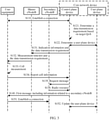
- FIG. 2 shows a data transmission method according to an embodiment of the present invention. As shown in FIG. 2 , a method 100 includes the following steps.
- S110 User equipment UE connects to a core network device by using a master eNodeB (Master NodeB, "M-NB" for short).
- M-NB Master NodeB
- the core network device includes a control plane device (CP function) and a user plane device (User Plane Function, "UP Function” for short).
- the UE may select, based on signal strength and/or coverage, a NodeB used when performing non-access stratum (Non-access Stratum, "NAS” for short) communication with the core network device. For example, the UE may select a NodeB having largest coverage from NodeBs whose signal strength satisfies a requirement, to perform NAS communication with the CP function.
- the CP Function records, as the M-NB, the NodeB used when the UE performs NAS communication with the CP function.
- a control plane device determines a data transmission requirement of the user equipment UE.
- the UE sends, to the CP function, a request for establishing a user plane.
- the request for establishing a user plane carries target quality of service (Quality of Service, "QoS" for short).
- another core network device such as an application device (Application Function) sends, to the CP function, a request for establishing a user plane connection.
- the request carries target QoS.
- the user plane connection may refer to a bearer (Bearer) or a data transmission path between the UE and the UP function.
- S120 includes S121 and S122.
- a CP function determines a data transmission requirement of the UE based on target QoS in a request.
- the target QoS may be understood as a specific requirement on a QoS parameter during data transmission.
- the QoS parameter includes a priority, reliability, a throughput, a latency, and the like.
- the target QoS requires that the latency during data transmission is less than 50 ms.
- the data transmission requirement may be understood as a requirement on transmission during data transmission, and for example, may be a low-latency requirement, a high-rate requirement, a high-reliability requirement, or a small-data requirement.
- the CP function considers that a requirement of the UE on transmission during data transmission is a low-latency requirement.
- the data transmission requirement may be understood as requiring data to be transmitted by using a 3G access network, a 4G access network, or a 5G access network.
- the CP function may consider that the UE requires to transmit data by using the 5G access network.
- the CP function selects, based on the target QoS in the request, a UP function supporting the target QoS, and establishes, with the selected UP function, a bearer (Bearer) satisfying the target QoS.
- the CP function determines a secondary eNodeB based on the data transmission requirement.
- S130 includes the following steps.
- the CP function sends a message to the M-NB, where the message carries indication information for instructing the M-NB to allocate a measurement timeslot to the UE and the data transmission requirement.
- the data transmission requirement may be carried in a NAS message.
- the M-NB does not obtain or cannot obtain information in the NAS message through parsing, and directly forwards the received NAS message to the UE.
- the data transmission requirement may alternatively be carried in a message between the CP function and the M-NB.
- the M-NB parses the received message and forwards the data transmission requirement in the message to the UE.
- S132 The M-NB allocates the measurement timeslot to the UE, and sends, to the UE, the measurement timeslot and the data transmission requirement received in S131.
- S133 The UE measures a cell based on the measurement timeslot allocated by the M-NB, where the measured cell is a cell satisfying the data transmission requirement.
- a system information block (System Information Block, "SIB" for short) message received by the UE from an NB includes a data transmission requirement supported by each of cells of the NB.
- the UE learns, based on the SIB message, the data transmission requirement supported by each cell, and then compares the data transmission requirement sent by the M-NB and the data transmission requirement that is supported by each cell and that is learned from the SIB message, to determine a cell needing to be measured.
- signal strength of each cell satisfying a condition may be selected for measuring.
- S134 The UE reports information about a target cell to the CP function based on a measurement result.
- the UE determines, from a plurality of cells to be measured and based on the measurement result of the signal strength of the cell to be measured that is determined in S133, the target cell that is to be reported to the CP function, and reports information about the determined target cell to the CP function.
- a signal strength threshold may be preset.
- the M-NB sends a signal strength threshold to the UE.
- the UE determines, as the target cell to be reported, a cell whose signal strength is greater than the signal strength threshold in the plurality of cells to be measured.
- the information about the target cell that is reported by the UE may include the signal strength of the target cell, load status information of the target cell, and the like.
- the information about the target cell may further include a cell identifier (a cell ID) of the target cell or a base station identifier (a base station ID) of an NodeB to which the target cell belongs.
- a cell ID a cell ID
- a base station identifier a base station ID of an NodeB to which the target cell belongs.
- the CP function determines an S-NB based on the information about the target cell that is reported by the UE, and sends a request message to the S-NB, to request the S-NB to allocate, to the UE, a radio resource for accessing the S-NB.
- the CP function determines the S-NB based on the information about the target cell
- the CP function determines the S-NB based on the cell identifier of the target cell.
- the CP function determines the S-NB based on the base station identifier.
- the CP function selects one target cell from the two or more target cells, and determines the S-NB based on information about the selected target cell.
- the CP function may select one target cell from the two or more target cells based on at least two of the following conditions: signal strength of each of the two or more target cells, a load status of a NodeB to which each of the two or more target cells belongs, and a connection status between a NodeB to which each of the two or more target cells belongs and the CP function.
- the CP function may perform selection based on the signal strength of each of the two or more target cells and the load status of the NodeB to which each target cell belongs.
- a set of target cells belonging to NodeBs whose load is less than a load threshold may be first determined, then a target cell having highest signal strength is selected from the determined set of the target cells, and a NodeB to which the target cell belongs is determined as the S-NB.
- selection may be performed based on the signal strength of each of the two or more target cells and the connection relationship between the NodeB to which each target cell belongs and the CP function.
- a set of target cells belonging to NodeBs having an interface with the CP function may be first determined, then a target cell having highest signal strength is selected from the determined set of the target cells, and a NodeB to which the target cell belongs is determined as the S-NB.
- the request message sent by the CP function to the S-NB may further include the target QoS and indication information for instructing the S-NB to allocate the radio resource to the UE.
- the S-NB After receiving the target QoS, the S-NB allocates, to the UE, the radio resource satisfying the target QoS.
- the CP function receives a message that is sent by the S-NB and that includes the radio resource.
- the S-NB may send the radio resource to the CP function by using a container (Container).
- Container Container
- S130 includes the following steps.
- the CP function sends a message to the M-NB, where the message carries the data transmission requirement of the UE.
- the M-NB determines a cell list of a cell satisfying the data transmission requirement.
- Data transmission requirements supported by cells of NBs surrounding the M-NB may be preconfigured on the M-NB. After receiving the data transmission requirement sent by the CP function, the M-NB may determine, in the cells of the surrounding NBs based on the preconfigured data transmission requirements supported by the cells of the surrounding NBs, a cell satisfying the received data transmission requirement.
- the M-NB may receive messages that are sent by surrounding NBs and that carry data transmission requirements supported by cells of the NBs, parse the received messages to obtain the data transmission requirements supported by the cells of the surrounding NBs, and after receiving the data transmission requirement sent by the CP function, determine, in the cells of the surrounding NBs based on the data transmission requirements that are supported by the cells of the surrounding NBs and that are obtained through parsing, a cell satisfying the received data transmission requirement.
- the M-NB sends measurement configuration information to the UE, where the measurement configuration information includes the cell list in S137, and receives a measurement result that is reported by the UE and that is obtained by measuring the cell in the cell list based on the measurement configuration information.
- the measurement configuration message sent by the M-NB to the UE may further include information such as a measurement timeslot allocated by the M-NB to the UE and a signal strength threshold.
- the measurement configuration message includes the information, namely, the signal strength threshold
- the UE reports, to the M-NB, a measurement result of only a cell whose signal strength is higher than the signal strength threshold.
- the M-NB determines a target cell based on the measurement result obtained through measurement, and reports information about the target cell to the CP function.
- the M-NB may report, to the CP function, received information about all the cells that is reported by the UE.
- the M-NB may select one or more cells from a plurality of cells reported by the UE, and report information about the one or more cells to the CP function.
- the M-NB may report, to the CP function, information about three cells whose load is relatively light in the plurality of cells reported by the UE.
- the CP function determines an S-NB based on the information about the target cell that is reported by the UE, and sends a request message to the S-NB, to request the S-NB to allocate, to the UE, a radio resource for accessing the S-NB.
- the CP function receives a message that is sent by the S-NB and that includes the radio resource.
- S140 The UE receives a first message that is sent by the control plane entity and that includes information related to the secondary eNodeB.
- the CP function sends, to the UE by using a NAS message, a received container that is sent by the S-NB in S136 and that includes the radio resource.
- the NAS message may further include an S-NB instruction, and the S-NB instruction is used to instruct the UE to access the S-NB.
- S150 The UE performs, by using the secondary eNodeB based on the first message, data transmission satisfying the data transmission requirement.
- S150 includes S151 and S152.
- S151 The UE establishes a connection to the S-NB based on the radio resource in a container.
- the UE establishes a user plane connection to the S-NB.
- the UE may store a correspondence between target QoS and an identifier of a user plane connection.
- a user plane connection to be used may be determined based on required QoS and the stored correspondence between the QoS and the identifier of the user plane connection.
- the CP function updates the UP function, to establish a connection between the S-NB and the UP function. Subsequently, the UE may perform data transmission by using the S-NB.
- the UE may not need to be always connected to the M-NB and the S-NB.
- the CP function may send, to the M-NB, a message carrying an inactive timer (Inactive Timer) for deactivating the M-NB, so that the M-NB does not release a signaling radio bearer SRB and a data radio bearer DRB between the M-NB and the UE.
- Inactive Timer Inactive Timer
- the CP function sends, to the M-NB, a message for activating the inactive timer, so that the M-NB releases the SRB and the DRB between the M-NB and the UE when the inactive timer expires, and the UE enters the idle state in a service range of the M-NB.
- the CP function may send, to the M-NB, a message indicating not to release an SRB between the M-NB and the UE, so that the M-NB releases only a DRB between the M-NB and the UE and does not release the SRB between the M-NB and the UE when an inactive timer expires.
- the CP function sends, to the M-NB, indication information indicating to release the SRB, so that the M-NB releases the SRB between the M-NB and the UE.
- the CP function selects an S-NB, and sends, to the UE by using the S-NB, an update message carrying an identity change instruction, to change an identity of an S-NMB to the S-NB. Subsequently, the UE may perform NAS communication with the CP function by using the S-NB.
- the S-NB selected by the CP function is an NB having largest coverage in all NBs connected to the UE.
- the UE when in connected mode in the service range of the S-NB, the UE continuously sends an AS stratum heartbeat message to the M-NB, to prevent the inactive timer in the M-NB from expiring.
- the UE stops sending the AS stratum heartbeat message to the M-NB.
- the UE selects an S-NB, and sends, to the CP function by using the S-NB, an update message carrying an identity change instruction, to change an identity of the S-NB to an M-NB.
- the S-NB selected by the UE is an NB having largest coverage in all NBs connected to the UE.
- the UE enters the idle state in the service range of the S-NB above means that the UE enters the idle state in the service ranges of all the NBs connected to the UE.
- FIG. 5 shows a method 200 , not covered by the claims, for triggering UE to enter a connected state when the UE is called.
- the method 200 includes the following steps.
- a UP Function receives downlink data, finds that there is no connection to an NB, and sends a downlink data notification (Downlink Data Notification) message to a CP function.
- a downlink data notification Downlink Data Notification
- a destination Internet Protocol (Internet Protocol, "IP" for short) address of the downlink data that is received by the UP function and that is sent by a network is an IP address of UE.
- IP Internet Protocol
- the CP function determines an M-NB of the UE based on stored context information of the UE, and performs S230 and S240; or if the UE is in connected mode in an M-NB, the CP function directly performs S250.
- the CP function sends a paging (paging) message to the UE by using the determined M-NB.
- S240 The UE sends a service request (Service Request) message to the CP function by using the M-NB, to request to enter a connected state.
- Service Request Service Request
- an SRB and a DRB between the M-NB and the UE may be recovered.
- the UE has no data on a bearer corresponding to the M-NB, only the SRB between the M-NB and the UE may be recovered, and the DRB between the M-NB and the UE may not be recovered.
- the CP function determines a data transmission requirement of the UE based on stored context information of the UE and an identifier of the UP function.
- the context information of the UE stores a correspondence between a data transmission requirement of each bearer on the UE and an identifier of a UP function.
- the CP function may determine, based on the identifier of the UP function, a data transmission requirement corresponding to a bearer to be recovered.
- S260 Perform S130 to S150 in the method 100.
- FIG. 6 shows a method 300 , not covered by the claims, for triggering UE to enter a connected state when the UE makes a call.
- the method 300 includes the following steps.
- S310 When to send data of particular QoS, UE in idle mode determines a bearer ID of a bearer to be used.
- the UE may determine, based on a pre-stored correspondence between QoS and an identifier of a bearer, the bearer ID corresponding to the particular QoS.
- S320 The UE sends a service request message to a CP function, where the message includes the bearer ID.
- the CP function determines a data transmission requirement of the UE based on stored context information of the UE and the bearer ID.
- S340 Perform S130 to S150 in the method 100.
- the context information of the UE includes information about a bearer on the UE, identification information of each bearer, QoS information corresponding to each bearer, security context information, and the like.
- user equipment 10 includes:
- the NAS message between the user equipment according to this embodiment of the present invention and the core network device is transmitted by using only one base station, and the user equipment accesses, based on information that is sent by the core network device by using the base station and that is related to another base station, the another base station to perform data transmission. In this way, the user equipment can access different base stations to satisfy different data transmission requirements.
- the information related to the second base station includes radio resource information.
- the radio resource information includes a radio resource used by the user equipment to access the second base station.
- the data transmission unit 12 is specifically configured to: access the second base station by using the radio resource; establish, by using the second base station, a user plane connection used for data transmission; and perform data transmission by using the user plane connection.
- the transceiver unit 11 is further configured to send information about a target cell to the core network device, so that the core network device determines the second base station based on the information about the target cell.
- the user equipment further includes a first processing unit 13.
- the transceiver unit 11 Before the transceiver unit 11 sends the information about the target cell to the core network device, the transceiver unit 11 is further configured to receive first measurement configuration information and a data transmission requirement that are sent by the first base station.
- the processing unit 13 is configured to measure, based on the first measurement configuration information, a cell supporting the data transmission requirement, to obtain the information about the target cell.
- the user equipment further includes a second processing unit 14.
- the transceiver unit 11 is specifically configured to receive second measurement configuration information and a cell set supporting the data transmission requirement that are sent by the first base station.
- the second processing unit 14 is specifically configured to measure a cell in the cell set based on the second measurement configuration information.
- the transceiver unit 11 is specifically configured to send, to the first base station, a measurement result obtained by measuring the cell in the cell set, so that the first base station determines the target cell based on the measurement result and sends the information about the target cell to the core network device.
- the information about the target cell includes a cell identifier of the target cell and/or a base station identifier of a base station to which the target cell belongs.
- the transceiver unit 11 is further configured to continuously send an access stratum AS heartbeat message to the first base station, and stop sending the AS heartbeat message to the first base station if the user equipment is in idle mode in a service range of the second base station.
- the transceiver unit 11 is further configured to send a second message to the core network device by using the second base station if the user equipment is in idle mode in a service range of the first base station and is in connected mode in a service range of the second base station.
- the second message is used to request to perform transmission of the NAS message with the core network device by using the second base station.
- the transceiver unit 11 is further configured to: send a third message to the core network device, where the third message is used to request to establish, on the user equipment, a user plane connection satisfying target quality of service QoS, so that the core network device determines the data transmission requirement based on the target QoS; or send, to the core network device, a fourth message used to request to enter a connected state, where the fourth message includes identification information of a bearer to be used when the user equipment performs data transmission, so that the core network device determines the data transmission requirement based on stored context information of the user equipment and the identification information of the bearer.
- the user equipment 10 herein is presented in a form of functional units.
- the term "unit” herein may refer to an application-specific integrated circuit (Application-Specific Integrated Circuit, "ASIC" for short), an electronic circuit, a processor (for example, a shared processor, a dedicated processor, or a combination of shared or dedicated processors) configured to perform one or more software or firmware programs and a memory, an integrated logic circuit, and/or another appropriate component supporting the described functions.
- ASIC Application-Specific Integrated Circuit
- the user equipment 10 may be configured to perform each procedure and/or step in the methods 100 to 300 in the foregoing method embodiments. To avoid repetition, details are not described herein again.
- a core network device 20 includes:
- the core network device selects, based on the data transmission requirement of the user equipment, an appropriate base station for the user equipment to access a network to perform data transmission. In this way, the user equipment can satisfy different requirements on quality of service by using different radio access technologies.
- the information related to the second base station includes radio resource information.
- the radio resource information includes a radio resource used by the UE to access the second base station.
- the transceiver unit 22 Before the transceiver unit 22 sends the first message to the UE by using the first base station, the transceiver unit 22 is further configured to: send a second message to the second base station, where the second message is used to request the second base station to allocate, to the UE, the radio resource used by the UE to access the second base station; and receive the radio resource information sent by the second base station.
- the transceiver unit 22 is further configured to: send the data transmission requirement to the UE by using the first base station, and receive information about a target cell that is sent by the UE.
- the information about the target cell is determined by the UE based on the data transmission requirement.
- the processing unit 21 is specifically configured to determine the second base station based on the information about the target cell.
- the transceiver unit 22 is specifically configured to send a third message to the first base station, where the third message includes indication information and the data transmission requirement, so that the first base station sends measurement configuration information and the data transmission requirement to the UE based on the indication information, and the UE determines the information about the target cell based on the measurement configuration information and the data transmission requirement.
- the transceiver unit 22 is further configured to: send a fourth message to the first base station, where the fourth message includes the data transmission requirement, so that the first base station determines a cell set supporting the data transmission requirement; and receive the information about the target cell that is sent by the first base station, where the information about the target cell is obtained by the UE by measuring a cell in the cell set and is sent to the first base station.
- the processing unit 21 is specifically configured to determine the second base station based on the information about the target cell.
- the information about the target cell includes a cell identifier of the target cell and/or a base station identifier of a base station to which the target cell belongs.
- the processing unit 21 is specifically configured to determine the second base station based on the cell identifier and/or the base station identifier.
- the processing unit 21 is specifically configured to: select a target cell from the at least two target cells based on at least two of the following information: signal strength information of each of the at least two target cells, load information of a base station to which each of the at least two target cells belongs, and a connection relationship between a base station to which each of the at least two target cells belongs and the first core network device; and determine the second base station based on information about the selected target cell.
- the processing unit 21 is further configured to: deactivate an inactive timer in the first base station, so that the first base station does not release a signaling radio bearer SRB and a data radio bearer DRB between the first base station and the UE; and activate the inactive timer if determining that the UE enters an idle state in a service range of the second base station, so that the first base station releases the SRB and the DRB when the inactive timer expires.
- the transceiver unit 22 is further configured to: send a fifth message to the first base station, where the fifth message is used to instruct the first base station to release only a data radio bearer DRB between the first base station and the UE when an inactive timer in the first base station expires; and send a sixth message to the first base station if the processing unit 21 determines that the UE enters an idle state in a service range of the second base station, where the sixth message is used to instruct the first base station to release a signaling radio bearer SRB between the first base station and the UE.
- the transceiver unit 22 is further configured to send a seventh message to the UE by using the second base station if the processing unit 21 determines that the UE enters an idle state in a service range of the first base station and is in connected mode in a service range of the second base station.
- the seventh message is used to instruct the UE to perform transmission of the NAS message with the core network device by using the second base station.
- the transceiver unit 22 is further configured to receive an eighth message.
- the eighth message is used to request to establish, on the UE, a user plane connection satisfying target quality of service QoS.
- the processing unit 21 is specifically configured to determine the data transmission requirement based on the target QoS.
- the transceiver unit 22 is further configured to receive a ninth message that is sent by the UE and that is used to request to enter the connected state.
- the ninth message includes identification information of a bearer to be used when the UE performs data transmission.
- the processing unit 21 is specifically configured to determine the data transmission requirement based on stored context information of the UE and the identification information of the bearer.
- the transceiver unit 22 is further configured to receive a tenth message sent by a second core network device.
- the tenth message is used to notify the core network device that the second core network device receives downlink data whose destination Internet Protocol IP address is an IP address of the UE.
- the processing unit 21 is specifically configured to determine the data transmission requirement based on stored context information of the UE and identification information of the second core network device.
- the core network device 20 herein is presented in a form of functional units.
- the term "unit” herein may refer to an application-specific integrated circuit (Application-Specific Integrated Circuit, "ASIC" for short), an electronic circuit, a processor (for example, a shared processor, a dedicated processor, or a combination of shared or dedicated processors) configured to perform one or more software or firmware programs and a memory, an integrated logic circuit, and/or another appropriate component supporting the described functions.
- ASIC Application-Specific Integrated Circuit
- the core network device 20 may be configured to perform each procedure and/or step in the methods 100 to 300 in the foregoing method embodiments. To avoid repetition, details are not described herein again.
- an embodiment of the present invention further provides user equipment 100.
- the user equipment 100 includes a processor 101, a receiver 102, a transmitter 103, and a memory 104.
- the processor 101, the memory 104, the receiver 102, and the transmitter 103 are connected by using a bus system 105.
- the memory 104 is configured to store an instruction.
- the processor 101 is configured to execute the instruction stored in the memory 104, to control the receiver 102 to receive a signal and control the transmitter 103 to send a signal.
- the receiver 102 is configured to receive a first message sent by a core network device by using a first base station.
- the first message includes information related to a second base station.
- the processor 101 is configured to: perform transmission of a non-access stratum NAS message with the core network device by using the first base station, and perform data transmission by using the second base station based on the information related to the second base station.
- the NAS message is transmitted only by using the first base station
- the NAS message between the user equipment according to this embodiment of the present invention and the core network device is transmitted by using only one base station, and the user equipment accesses, based on information that is sent by the core network device by using the base station and that is related to another base station, the another base station to perform data transmission. In this way, the user equipment can access different base stations to satisfy different data transmission requirements.
- the processor 101 may be a central processing unit (Central Processing Unit, "CPU” for short), or may be another general purpose processor, a digital signal processor (DSP), an application-specific integrated circuit (ASIC), a field programmable gate array (FPGA), or another programmable logic device, discrete gate or transistor logic device, discrete hardware component, or the like.
- the general purpose processor may be a microprocessor, or the processor may be any conventional processor or the like.
- the memory 104 may include a read-only memory and a random access memory, and provide an instruction and data to the processor 101.
- a part of the memory 104 may further include a non-volatile random access memory.
- the memory 104 may further store information about a device type.
- the bus system 105 may further include a power bus, a control bus, a status signal bus, and the like, in addition to a data bus.
- a power bus may further include a power bus, a control bus, a status signal bus, and the like, in addition to a data bus.
- various types of buses in the figure are marked as the bus system 105.
- steps in the foregoing methods can be implemented by using a hardware integrated logic circuit in the processor 101, or by using instructions in a form of software.
- the steps of the method disclosed with reference to the embodiments of the present invention may be directly performed by a hardware processor, or may be performed by using a combination of hardware in the processor and a software module.
- the software module may be located in a mature storage medium in the art, such as a random access memory, a flash memory, a read-only memory, a programmable read-only memory, an electrically erasable programmable memory, a register, or the like.
- the storage medium is located in the memory 104, and the processor 101 reads information in the memory 104 and completes the steps in the foregoing methods in combination with hardware of the processor 101. To avoid repetition, details are not described herein again.
- the information related to the second base station includes radio resource information.
- the radio resource information includes a radio resource used by the user equipment to access the second base station.
- the processor 101 is specifically configured to: access the second base station by using the radio resource; establish, by using the second base station, a user plane connection used for data transmission; and perform data transmission by using the user plane connection.
- the transmitter 103 is further configured to send information about a target cell to the core network device, so that the core network device determines the second base station based on the information about the target cell.
- the receiver 102 before the transmitter 103 sends the information about the target cell to the core network device, the receiver 102 is further configured to receive first measurement configuration information and a data transmission requirement that are sent by the first base station.
- the processor 101 is configured to measure, based on the first measurement configuration information, a cell supporting the data transmission requirement, to obtain the information about the target cell.
- the receiver 102 is specifically configured to receive second measurement configuration information and a cell set supporting the data transmission requirement that are sent by the first base station.
- the processor 101 is specifically configured to measure a cell in the cell set based on the second measurement configuration information.
- the transmitter 103 is specifically configured to send, to the first base station, a measurement result obtained by measuring the cell in the cell set, so that the first base station determines the target cell based on the measurement result and sends the information about the target cell to the core network device.
- the information about the target cell includes a cell identifier of the target cell and/or a base station identifier of a base station to which the target cell belongs.
- the transmitter 103 is further configured to continuously send an access stratum AS heartbeat message to the first base station, and stop sending the AS heartbeat message to the first base station if the user equipment is in idle mode in a service range of the second base station.
- the transmitter 103 is further configured to send a second message to the core network device by using the second base station if the user equipment is in idle mode in a service range of the first base station and is in connected mode in a service range of the second base station.
- the second message is used to request to perform transmission of the NAS message with the core network device by using the second base station.
- the transmitter 103 is further configured to: send a third message to the core network device, where the third message is used to request to establish, on the user equipment, a user plane connection satisfying target quality of service QoS, so that the core network device determines the data transmission requirement based on the target QoS; or send, to the core network device, a fourth message used to request to enter a connected state, where the fourth message includes identification information of a bearer to be used when the user equipment performs data transmission, so that the core network device determines the data transmission requirement based on stored context information of the user equipment and the identification information of the bearer.
- the user equipment 100 may correspond to the user equipment 10 in the embodiments of the present invention, and may correspond to the user equipment performing the methods 100 to 300 according to the embodiments of the present invention.
- the foregoing and another operation and/or function of each module in the user equipment 100 are respectively intended to implement a corresponding procedure corresponding to the user equipment in the methods shown in FIG. 2 to FIG. 6 .
- details are not described herein again.
- the NAS message between the user equipment according to this embodiment of the present invention and the core network device is transmitted by using only one base station, and the user equipment accesses, based on information that is sent by the core network device by using the base station and that is related to another base station, the another base station to perform data transmission. In this way, the user equipment can access different base stations to satisfy different data transmission requirements.
- an embodiment of the present invention further provides a core network device 200.
- the core network device 200 includes a processor 201, a receiver 202, a transmitter 203, and a memory 204.
- the processor 201, the memory 204, the receiver 202, and the transmitter 203 are connected by using a bus system 205.
- the memory 204 is configured to store an instruction.
- the processor 201 is configured to execute the instruction stored in the memory 204, to control the receiver 202 to receive a signal and control the transmitter 203 to send a signal.
- the processor 201 is configured to determine a data transmission requirement of user equipment UE.
- the processor 201 is further configured to determine a second base station based on the data transmission requirement.
- the transmitter 203 is configured to send a first message to the UE by using the first base station, where the first message includes information related to the second base station, so that the UE performs transmission of a non-access stratum NAS message with the core network device by using the first base station and performs, by using the second base station based on the information related to the second base station, data transmission satisfying the data transmission requirement.
- the NAS message is transmitted only by using the first base station.
- the core network device selects, based on the data transmission requirement of the user equipment, an appropriate base station for the user equipment to access a network to perform data transmission. In this way, the user equipment can satisfy different requirements on quality of service by using different radio access technologies.
- the processor 201 may be a central processing unit (Central Processing Unit, "CPU” for short), or may be another general purpose processor, a digital signal processor (DSP), an application-specific integrated circuit (ASIC), a field programmable gate array (FPGA), or another programmable logic device, discrete gate or transistor logic device, discrete hardware component, or the like.
- the general purpose processor may be a microprocessor, or the processor may be any conventional processor or the like.
- the memory 204 may include a read-only memory and a random access memory, and provide an instruction and data to the processor 201.
- a part of the memory 204 may further include a non-volatile random access memory.
- the memory 204 may further store information about a device type.
- the bus system 205 may further include a power bus, a control bus, a status signal bus, and the like, in addition to a data bus. However, for clear description, various types of buses in the figure are marked as the bus system 205.
- steps in the foregoing methods can be implemented by using a hardware integrated logic circuit in the processor 201, or by using instructions in a form of software.
- the steps of the method disclosed with reference to the embodiments of the present invention may be directly performed by a hardware processor, or may be performed by using a combination of hardware in the processor and a software module.
- the software module may be located in a mature storage medium in the art, such as a random access memory, a flash memory, a read-only memory, a programmable read-only memory, an electrically erasable programmable memory, a register, or the like.
- the storage medium is located in the memory 204, and the processor 201 reads information in the memory 204 and completes the steps in the foregoing methods in combination with hardware of the processor 201. To avoid repetition, details are not described herein again.
- the information related to the second base station includes radio resource information.
- the radio resource information includes a radio resource used by the UE to access the second base station.
- the transmitter 203 Before the transmitter 203 sends the first message to the UE by using the first base station, the transmitter 203 is further configured to: send a second message to the second base station, where the second message is used to request the second base station to allocate, to the UE, the radio resource used by the UE to access the second base station; and receive the radio resource information sent by the second base station.
- the transmitter 203 is further configured to send the data transmission requirement to the UE by using the first base station.
- the receiver 202 is configured to receive information about a target cell that is sent by the UE. The information about the target cell is determined by the UE based on the data transmission requirement.
- the processor 201 is specifically configured to determine the second base station based on the information about the target cell.
- the transmitter 203 is specifically configured to send a third message to the first base station, where the third message includes indication information and the data transmission requirement, so that the first base station allocates measurement configuration information and the data transmission requirement to the UE based on the indication information, and the UE determines the information about the target cell based on the measurement configuration information and the data transmission requirement.
- the transmitter 203 is further configured to: send a fourth message to the first base station, where the fourth message includes the data transmission requirement, so that the first base station determines a cell set supporting the data transmission requirement; and receive the information about the target cell that is sent by the first base station, where the information about the target cell is obtained by the UE by measuring a cell in the cell set and is sent to the first base station.
- the information about the target cell includes a cell identifier of the target cell and/or a base station identifier of a base station to which the target cell belongs.
- the processor 201 is specifically configured to determine the second base station based on the cell identifier and/or the base station identifier.
- the processor 201 is specifically configured to: select a target cell from the at least two target cells based on at least two of the following information: signal strength information of each of the at least two target cells, load information of a base station to which each of the at least two target cells belongs, and a connection relationship between a base station to which each of the at least two target cells belongs and the first core network device; and determine the second base station based on information about the selected target cell.
- the processor 201 is further configured to: deactivate an inactive timer in the first base station, so that the first base station does not release a signaling radio bearer SRB and a data radio bearer DRB between the first base station and the UE; and activate the inactive timer if determining that the UE enters an idle state in a service range of the second base station, so that the first base station releases the SRB and the DRB when the inactive timer expires.
- the transmitter 203 is further configured to: send a fifth message to the first base station, where the fifth message is used to instruct the first base station to release only a data radio bearer DRB between the first base station and the UE when an inactive timer in the first base station expires; and send a sixth message to the first base station if the processor 101 determines that the UE enters an idle state in a service range of the second base station, where the sixth message is used to instruct the first base station to release a signaling radio bearer SRB between the first base station and the UE.
- the transmitter 203 is further configured to send a seventh message to the UE by using the second base station if the processor 201 determines that the UE enters an idle state in a service range of the first base station and is in connected mode in a service range of the second base station.
- the seventh message is used to instruct the UE to perform transmission of the NAS message with the core network device by using the second base station.
- the receiver 202 is further configured to receive an eighth message.
- the eighth message is used to request to establish, on the UE, a user plane connection satisfying target quality of service QoS.
- the processor 201 is specifically configured to determine the data transmission requirement based on the target QoS.
- the receiver 202 is further configured to receive a ninth message that is sent by the UE and that is used to request to enter the connected state.
- the ninth message includes identification information of a bearer to be used when the UE performs data transmission.
- the processor 201 is specifically configured to determine the data transmission requirement based on stored context information of the UE and the identification information of the bearer.
- the receiver 202 is further configured to receive a tenth message sent by a second core network device.
- the tenth message is used to notify the core network device that the second core network device receives downlink data whose destination Internet Protocol IP address is an IP address of the UE.
- the processor 201 is specifically configured to determine the data transmission requirement based on stored context information of the UE and identification information of the second core network device.
- the core network device 200 may correspond to the core network device 20 in the embodiments of the present invention, and may correspond to the core network device performing the methods 100 to 300 in the embodiments of the present invention.
- the foregoing and another operation and/or function of each module in the core network device 200 are respectively intended to implement a corresponding procedure corresponding to the core network device in the methods in FIG. 2 to FIG. 6 .
- details are not described herein again.
- the core network device selects, based on the data transmission requirement of the user equipment, an appropriate base station for the user equipment to access a network to perform data transmission. In this way, the user equipment can satisfy different requirements on quality of service by using different radio access technologies.
- the disclosed system, apparatus, and method may be implemented in other manners.
- the described apparatus embodiment is merely an example.
- the unit division is merely logical function division and may be other division in actual implementation.
- a plurality of units or components may be combined or integrated into another system, or some features may be ignored or not performed.
- the displayed or discussed mutual couplings or direct couplings or communication connections may be implemented by using some interfaces.
- the indirect couplings or communication connections between the apparatuses or units may be implemented in electronic, mechanical, or other forms.
- the units described as separate parts may or may not be physically separate, and parts displayed as units may or may not be physical units, may be located in one position, or may be distributed on a plurality of network units. Some or all of the units may be selected based on actual requirements to achieve the objectives of the solutions of the embodiments.
- functional units in the embodiments of the present invention may be integrated into one processing unit, or each of the units may exist alone physically, or two or more units are integrated into one unit.
- the functions When the functions are implemented in the form of a software functional unit and sold or used as an independent product, the functions may be stored in a computer-readable storage medium. Based on such an understanding, the technical solutions of the present invention essentially, or the part contributing to the prior art, or some of the technical solutions may be implemented in a form of a software product.
- the computer software product is stored in a storage medium, and includes several instructions for instructing a computer device (which may be a personal computer, a server, or a network device) to perform all or some of the steps of the methods described in the embodiments of the present invention.
- the foregoing storage medium includes: any medium that can store program code, such as a USB flash drive, a removable hard disk, a read-only memory (ROM, Read-Only Memory), a random access memory (RAM, Random Access Memory), a magnetic disk, or an optical disc.
- program code such as a USB flash drive, a removable hard disk, a read-only memory (ROM, Read-Only Memory), a random access memory (RAM, Random Access Memory), a magnetic disk, or an optical disc.
Landscapes
- Engineering & Computer Science (AREA)
- Computer Networks & Wireless Communication (AREA)
- Signal Processing (AREA)
- Databases & Information Systems (AREA)
- Health & Medical Sciences (AREA)
- Cardiology (AREA)
- General Health & Medical Sciences (AREA)
- Mobile Radio Communication Systems (AREA)
Claims (12)
- Procédé de transmission de données permettant à un équipement d'utilisateur (UE) (10, 100) d'accéder à une pluralité de technologies d'accès radio (RAT) au moyen d'un dispositif de réseau central ayant un dispositif de plan de contrôle (CP) et un dispositif de plan d'utilisateur (UP) dans un système de communication incluant l'UE, une première station de base, une seconde station de base et ledit dispositif de réseau central ayant ledit dispositif CP et ledit dispositif UP, le procédé comprenant les étapes consistant à :envoyer (S134), par l'équipement d'utilisateur (UE), une information concernant une cellule cible au dispositif de réseau central, de sorte que le dispositif de réseau central détermine la seconde station de base sur la base de l'information concernant la cellule cible ;recevoir (S140), par l'équipement d'utilisateur (UE), un premier message envoyé par un dispositif de réseau central au moyen de la première station de base, le premier message comprenant une information relative à la seconde station de base ; etréaliser, par l'UE, une transmission d'un message par strate sans accès (NAS) avec le dispositif de réseau central au moyen de la première station de base, et réaliser une transmission de données au moyen de la seconde station de base sur la base de l'information relative à la seconde station de base, le message NAS étant transmis uniquement au moyen de la première station de base, l'UE réalisant uniquement une transmission de données au moyen de la seconde station de base,la première station de base étant un nœud B évolué maître (M-NB) et la seconde station de base un nœud B évolué secondaire (S-NB) appartenant à différentes technologies d'accès radio ; et dans lequel :1) l'UE demande au dispositif de réseau central, au moyen du nœud B évolué maître, d'établir un plan d'utilisateur en envoyant une QoS cible au dispositif CP, sur la base de quoi le dispositif CP du dispositif de réseau central détermine (S 120) une exigence de transmission de données de l'UE et sélectionne un dispositif UP prenant en charge la QoS cible et établit, avec le dispositif UP sélectionné, une porteuse satisfaisant à la QoS cible ;2) en réponse, le dispositif CP détermine ou sélectionne un nœud B évolué secondaire sur la base de l'exigence de transmission de données (S 130), ce qui inclut les étapes consistant à :a) envoyer (S131), par un dispositif CP, une instruction au M-NB pour affecter un intervalle de mesure et l'exigence de transmission de données ;b) envoyer (S132), par le M-NB, un intervalle de mesure affecté et l'exigence de transmission de données à l'UE ;c) mesurer (S133), par l'UE, une cellule satisfaisant à l'exigence de transmission de données en comparant l'exigence de transmission de données envoyée (S 132) par le M-NB à l'exigence de transmission de données qui est prise en charge par chaque cellule et qui est apprise à partir d'un message de bloc d'information de système (SIB) ;d) signaler (S 134), par l'UE, une information concernant une cellule cible au dispositif CP sur la base d'un résultat de mesure ;e) déterminer (S135), par le dispositif CP, le S-NB sur la base de l'information concernant la cellule cible signalée par l'UE et envoyer (S 135) un message de demande au S-NB pour affecter à un UE une ressource radio pour accéder au S-NB, etf) recevoir (S 136), par le dispositif CP, en provenance du S-NB, un message qui inclut la ressource radio ;3) après que le dispositif CP a déterminé le nœud B évolué secondaire, il envoie (S140) à l'UE, au moyen d'un message NAS, un premier message qui inclut la ressource radio envoyée par le S-NB et une instruction de S-NB qui est utilisée pour donner l'instruction à l'UE d'accéder au S-NB ;4) l'UE réalise (S150) une transmission de données satisfaisant à l'exigence de transmission de données au moyen du nœud B évolué secondaire sur la base du premier message en réalisant les deux étapes suivantes :l'UE établit (S151) une connexion de plan d'utilisateur avec le S-NB sur la base de la ressource radio dans un contenant ; etle dispositif CP met à jour (S 152) la fonction UP pour établir une connexion entre le S-NB et la fonction UP, puis l'UE réalise une transmission de données au moyen du S-NB.
- Procédé selon la revendication 1, dans lequel l'information concernant une cellule cible inclut la puissance de signal de la cellule cible, une information de station de charge de la cellule cible et un identifiant de cellule (ID de cellule) de la cellule cible ou un identifiant de station de base d'un nœud B évolué secondaire auquel la cellule cible appartient.
- Procédé selon la revendication 1 ou 2, dans lequel chacune des première et seconde stations de base prend en charge des transmissions de données exigeant que des données soient transmises au moyen d'un réseau d'accès 3G, d'un réseau d'accès 4G ou d'un réseau d'accès 5G.
- Procédé selon la revendication 1, dans lequel, pour déterminer le S-NB, le CP réalise la sélection d'une cellule cible parmi deux cellules cibles ou plus sur la base d'au moins deux des conditions suivantes :i) une puissance de signal de chacune des deux cellules cibles ou plus, un statut de charge d'un nœud B auquel chacune des deux cellules cibles ou plus appartient, auquel cas un ensemble de cellules cibles appartenant à des nœuds B dont la charge est inférieure à un seuil de charge est déterminé en premier, puis une cellule cible ayant une puissance de signal maximale est sélectionnée dans l'ensemble déterminé des cellules cibles, et un nœud B auquel la cellule cible appartient est déterminé comme étant le S-NB ; et/ouii) un statut de connexion entre un nœud B auquel chacune des deux cellules cibles ou plus appartient et le dispositif CP, auquel cas un ensemble de cellules cibles appartenant à des nœuds B ayant une interface avec le dispositif CP est déterminé en premier, puis une cellule cible ayant une puissance de signal maximale est sélectionnée dans l'ensemble déterminé des cellules cibles, et un nœud B auquel la cellule cible appartient est déterminé comme étant le S-NB.
- Procédé selon la revendication 1, dans lequel l'envoi, par l'UE, d'une information concernant une cellule cible au dispositif de réseau central comprend les étapes consistant à :recevoir, par l'UE, une seconde information de configuration de mesure et un ensemble de cellules prenant en charge l'exigence de transmission de données, qui sont envoyées par la première station de base ;mesurer, par l'UE, une cellule dans l'ensemble de cellules sur la base de la seconde information de configuration de mesure ; etenvoyer, par l'UE à la première station de base, un résultat de mesure obtenu en mesurant la cellule dans l'ensemble de cellules, de sorte que la première station de base détermine la cellule cible sur la base du résultat de mesure et envoie l'information concernant la cellule cible au dispositif de réseau central.
- Procédé selon l'une quelconque des revendications 3 à 5, dans lequel l'information concernant la cellule cible comprend un identifiant de cellule de la cellule cible et/ou un identifiant de station de base d'une station de base à laquelle la cellule cible appartient.
- Procédé selon l'une quelconque des revendications 1 à 6, le procédé comprenant en outre, après la réalisation, par l'UE, d'une transmission de données au moyen de la seconde station de base, les étapes consistant à :envoyer en continu, par l'UE, un message battement de cœur par strate d'accès (AS) à la première station de base ; etarrêter, par l'UE, l'envoi du message battement de cœur AS à la première station de base s'il est déterminé que l'UE est dans un mode d'inactivité à portée utile de la seconde station de base.
- Procédé selon l'une quelconque des revendications 1 à 6, le procédé comprenant en outre, après la réalisation, par l'UE, d'une transmission de données au moyen de la seconde station de base, l'étape consistant à :
envoyer, par l'UE, un deuxième message au dispositif de réseau central au moyen de la seconde station de base s'il est déterminé que l'UE est dans un mode d'inactivité à portée utile de la première station de base et dans un mode connecté à portée utile de la seconde station de base, le deuxième message étant utilisé pour demander de réaliser une transmission du message NAS avec le dispositif de réseau central au moyen de la seconde station de base. - Procédé selon la revendication 4, le procédé comprenant en outre, avant la réception, par l'UE d'un premier message envoyé par un dispositif de réseau central au moyen d'une première station de base, l'étape consistant à :envoyer (S110), par l'UE, un troisième message au dispositif de réseau central, le troisième message étant utilisé pour demander d'établir, sur l'UE, une connexion de plan d'utilisateur satisfaisant à une qualité de service (QoS) cible, de sorte que le dispositif de réseau central détermine l'exigence de transmission de données sur la base de la QoS cible ; ouenvoyer, par l'UE au dispositif de réseau central, un quatrième message utilisé pour demander d'entrer dans un état connecté, le quatrième message comprenant une information d'identification d'une porteuse à utiliser quand l'UE réalise une transmission de données, de sorte que le dispositif de réseau central détermine l'exigence de transmission de données sur la base d'une information contextuelle stockée de l'UE et de l'information d'identification de la porteuse.
- Procédé selon l'une quelconque des revendications 1 à 9, dans lequel le dispositif CP envoie au M-NB un message transportant un temporisateur inactif pour désactiver le M-NB pour empêcher le M-NB de libérer une porteuse radio de signalisation (SRB) et une porteuse radio de données (DRB) entre le M-NB et l'UE, et quand l'UE est connecté à portée utile du S-NB, l'UE envoyant en continu un message battement de cœur par strate d'accès (AS) au M-NB pour empêcher l'expiration du temporisateur inactif dans le M-NB, et quand l'UE entre dans un état d'inactivité à portée utile de la seconde station de base, l'UE arrêtant d'envoyer le message battement de cœur AS à la première station de base de sorte que, lorsque le temporisateur inactif dans la première station de base expire, l'UE entre dans l'état d'inactivité à portée utile de la première station de base.
- Procédé selon l'une quelconque des revendications 1 à 10, dans lequel en outre, après l'entrée de l'UE dans l'état d'inactivité à portée utile du M-NB, l'UE sélectionne un S-NB et envoie, au dispositif CP au moyen du S-NB, un message de mise à jour transportant une instruction de changement d'identité pour changer une identité du S-NB pour un M-NB, de préférence le S-NB sélectionné par l'UE ou le dispositif CP étant un NB ayant une couverture maximale parmi tous les NB connectés à l'UE.
- Système de communication incluant une première station de base, une seconde station de base et un dispositif de réseau central ayant un dispositif de plan de contrôle (CP) et un dispositif de plan d'utilisateur (UP), et un équipement d'utilisateur (10, 100) capable de réaliser une transmission de données au moyen d'une pluralité de technologies d'accès radio (RAT) au moyen dudit dispositif de réseau central, l'UE, le dispositif CP, le dispositif UP et le dispositif de réseau central étant conçus pour réaliser respectivement les étapes mentionnées dans une ou plusieurs des revendications 1 à 11.
Applications Claiming Priority (1)
| Application Number | Priority Date | Filing Date | Title |
|---|---|---|---|
| PCT/CN2016/081598 WO2017193293A1 (fr) | 2016-05-10 | 2016-05-10 | Procédé et dispositif d'émission de données |
Publications (3)
| Publication Number | Publication Date |
|---|---|
| EP3445128A1 EP3445128A1 (fr) | 2019-02-20 |
| EP3445128A4 EP3445128A4 (fr) | 2019-05-22 |
| EP3445128B1 true EP3445128B1 (fr) | 2022-02-23 |
Family
ID=60266173
Family Applications (1)
| Application Number | Title | Priority Date | Filing Date |
|---|---|---|---|
| EP16901248.1A Active EP3445128B1 (fr) | 2016-05-10 | 2016-05-10 | Procédé et dispositif d'émission de données |
Country Status (4)
| Country | Link |
|---|---|
| US (1) | US20190141769A1 (fr) |
| EP (1) | EP3445128B1 (fr) |
| CN (1) | CN108029150B (fr) |
| WO (1) | WO2017193293A1 (fr) |
Families Citing this family (10)
| Publication number | Priority date | Publication date | Assignee | Title |
|---|---|---|---|---|
| WO2018000363A1 (fr) | 2016-06-30 | 2018-01-04 | 华为技术有限公司 | Procédé, dispositif et système de réseau de transmission de données |
| US10631173B2 (en) * | 2016-09-02 | 2020-04-21 | Qualcomm Incorporated | Radio (NR) procedures for shared spectrum |
| CN108123783B (zh) * | 2016-11-29 | 2020-12-04 | 华为技术有限公司 | 数据传输方法、装置及系统 |
| EP3806575A1 (fr) * | 2017-01-16 | 2021-04-14 | Telefonaktiebolaget Lm Ericsson (Publ) | Mise à jour de zone de suivi dans rrc_inactif |
| US10798775B2 (en) * | 2017-08-10 | 2020-10-06 | Qualcomm Incorporated | Techniques and apparatuses for duplication bearer management |
| CN112637942A (zh) * | 2019-09-24 | 2021-04-09 | 深圳市万普拉斯科技有限公司 | 数据传输方法、装置及通信终端 |
| CN111277658A (zh) * | 2020-01-21 | 2020-06-12 | 神华神东电力有限责任公司 | 数据传输方法及远端数据中心 |
| CN113260083B (zh) * | 2020-02-12 | 2022-07-22 | 维沃移动通信有限公司 | 一种连接控制方法、装置和通信设备 |
| WO2022151283A1 (fr) * | 2021-01-14 | 2022-07-21 | 华为技术有限公司 | Procédé, appareil et système de communication |
| CN115276930A (zh) * | 2021-04-30 | 2022-11-01 | 北京三星通信技术研究有限公司 | 一种信息传输方法和设备 |
Family Cites Families (15)
| Publication number | Priority date | Publication date | Assignee | Title |
|---|---|---|---|---|
| CN101001184A (zh) * | 2006-01-09 | 2007-07-18 | 华为技术有限公司 | 一种接入分组数据网络的方法 |
| US7873710B2 (en) * | 2007-02-06 | 2011-01-18 | 5O9, Inc. | Contextual data communication platform |
| CN102238542A (zh) * | 2010-04-20 | 2011-11-09 | 中兴通讯股份有限公司 | 一种中继节点下用户设备的rrc重建方法和系统 |
| CN102761904B (zh) * | 2011-04-28 | 2017-10-10 | 中兴通讯股份有限公司 | 数据传输方法、设备及系统 |
| US9832672B2 (en) * | 2012-04-27 | 2017-11-28 | Mitsubishi Electric Corporation | Communication system |
| JP2015534355A (ja) * | 2012-09-14 | 2015-11-26 | インターデイジタル パテント ホールディングス インコーポレイテッド | 無線システムでWi−Fiオフローディングを行うためのモビリティ制御方法 |
| CN110087272B (zh) * | 2013-02-22 | 2021-10-08 | 三星电子株式会社 | 在多个e节点b和用户设备间提供同时连接的方法和系统 |
| CN104823507B (zh) * | 2013-03-06 | 2018-09-07 | 华为技术有限公司 | 通讯方法和设备 |
| US9813978B2 (en) * | 2013-03-08 | 2017-11-07 | Lg Electronics Inc. | Method and apparatus for establishing session in wireless communication system |
| EP2984877B1 (fr) * | 2013-04-10 | 2019-10-30 | LG Electronics Inc. | Procédé et appareil permettant d'exécuter une transition rapide vers un point d'accès d'une seconde technologie d'accès radio dans un système de communication sans fil |
| KR20140145524A (ko) * | 2013-06-13 | 2014-12-23 | 주식회사 케이티 | 듀얼 커넥티비티 구성 처리 방법 및 장치 |
| WO2015136122A1 (fr) * | 2014-03-14 | 2015-09-17 | Nec Europe Ltd. | Procédé, équipement d'utilisateur, noeud b évolué maître, et système de communication, pour une connectivité double |
| KR102631732B1 (ko) * | 2014-11-14 | 2024-01-30 | 인터디지탈 패튼 홀딩스, 인크 | 비인가 대역에서의 롱 텀 에볼루션(lte) 동작을 위한 채널 측정 및 보고 메커니즘을 위한 방법 및 프로시져 |
| US9398509B1 (en) * | 2015-01-07 | 2016-07-19 | Verizon Patent And Licensing Inc. | Dynamic hand-over parameter control |
| WO2016207904A1 (fr) * | 2015-06-24 | 2016-12-29 | Telefonaktiebolaget Lm Ericsson (Publ) | Procédés, nœuds de réseau, dispositif de communication, programmes informatiques et produits-programmes d'ordinateur pour le rétablissement d'une connexion |
-
2016
- 2016-05-10 US US16/300,395 patent/US20190141769A1/en not_active Abandoned
- 2016-05-10 WO PCT/CN2016/081598 patent/WO2017193293A1/fr not_active Ceased
- 2016-05-10 EP EP16901248.1A patent/EP3445128B1/fr active Active
- 2016-05-10 CN CN201680010364.5A patent/CN108029150B/zh active Active
Non-Patent Citations (1)
| Title |
|---|
| None * |
Also Published As
| Publication number | Publication date |
|---|---|
| WO2017193293A1 (fr) | 2017-11-16 |
| CN108029150A (zh) | 2018-05-11 |
| EP3445128A4 (fr) | 2019-05-22 |
| EP3445128A1 (fr) | 2019-02-20 |
| US20190141769A1 (en) | 2019-05-09 |
| CN108029150B (zh) | 2020-09-11 |
Similar Documents
| Publication | Publication Date | Title |
|---|---|---|
| EP4055985B1 (fr) | Capacités dynamiques multi-sim | |
| US11457398B2 (en) | Access category and establishment cause | |
| EP2946609B1 (fr) | Délestage optimisé vers un wlan en mobilité rat-3gppp | |
| EP3445128A1 (fr) | Procédé et dispositif d'émission de données | |
| EP3595358A1 (fr) | Procédé et dispositif de communication | |
| US9326309B2 (en) | Method and apparatus for supporting communication of multi-mode terminal | |
| TWI483636B (zh) | 行動通訊裝置、電信網路、及資料流量卸載方法 | |
| US9264984B2 (en) | Method and apparatus for transreceiving data in radio access system supporting multi-rat | |
| KR20210101310A (ko) | Amf 및 smf에서의 혼잡 제어 | |
| HK1217590A1 (zh) | 接入網發現和選擇 | |
| US9681369B2 (en) | Methods and devices for cell measurement and measurement control | |
| WO2020082945A1 (fr) | Procédé et dispositif d'équilibrage de charge | |
| US11191114B2 (en) | Method, apparatus and system for obtaining device-to-device communication resource | |
| US12069605B2 (en) | First wireless device, first network node, second wireless device, and methods performed thereby, for determining a status of a cell | |
| CN104519531B (zh) | 移动通信装置、存取网络、及操纵数据流量的方法 | |
| CN104871577B (zh) | 业务切换的方法、网络设备和用户设备 | |
| CN114930916B (zh) | 基于ue组的小区重选 | |
| US10306520B2 (en) | Handover method between heterogeneous wireless communication techniques and device for same | |
| CN107079328A (zh) | 管理至少一个核心网络中的过载 | |
| CN104170437A (zh) | 频点测量控制方法及基站、用户设备 | |
| CN110140397B (zh) | 小区切换过程中的信息传输方法和装置 | |
| US20130250905A1 (en) | Method and apparatus for transceiving data in a radio access system which supports a multi-radio access technology | |
| US10681702B2 (en) | Communication method and device | |
| US20170325150A1 (en) | Base station and processor | |
| WO2017003357A1 (fr) | Identification de dispositif dans des réseaux wlan et cellulaires étendus en interfonctionnement |
Legal Events
| Date | Code | Title | Description |
|---|---|---|---|
| STAA | Information on the status of an ep patent application or granted ep patent |
Free format text: STATUS: THE INTERNATIONAL PUBLICATION HAS BEEN MADE |
|
| PUAI | Public reference made under article 153(3) epc to a published international application that has entered the european phase |
Free format text: ORIGINAL CODE: 0009012 |
|
| STAA | Information on the status of an ep patent application or granted ep patent |
Free format text: STATUS: REQUEST FOR EXAMINATION WAS MADE |
|
| 17P | Request for examination filed |
Effective date: 20181115 |
|
| AK | Designated contracting states |
Kind code of ref document: A1 Designated state(s): AL AT BE BG CH CY CZ DE DK EE ES FI FR GB GR HR HU IE IS IT LI LT LU LV MC MK MT NL NO PL PT RO RS SE SI SK SM TR |
|
| AX | Request for extension of the european patent |
Extension state: BA ME |
|
| A4 | Supplementary search report drawn up and despatched |
Effective date: 20190418 |
|
| RIC1 | Information provided on ipc code assigned before grant |
Ipc: H04W 76/27 20180101ALN20190412BHEP Ipc: H04W 76/15 20180101AFI20190412BHEP Ipc: H04W 76/25 20180101ALN20190412BHEP Ipc: H04W 76/16 20180101ALN20190412BHEP |
|
| DAV | Request for validation of the european patent (deleted) | ||
| DAX | Request for extension of the european patent (deleted) | ||
| STAA | Information on the status of an ep patent application or granted ep patent |
Free format text: STATUS: EXAMINATION IS IN PROGRESS |
|
| 17Q | First examination report despatched |
Effective date: 20200316 |
|
| REG | Reference to a national code |
Ref country code: DE Ref legal event code: R079 Ref document number: 602016069474 Country of ref document: DE Free format text: PREVIOUS MAIN CLASS: H04W0076020000 Ipc: H04W0076150000 |
|
| GRAP | Despatch of communication of intention to grant a patent |
Free format text: ORIGINAL CODE: EPIDOSNIGR1 |
|
| STAA | Information on the status of an ep patent application or granted ep patent |
Free format text: STATUS: GRANT OF PATENT IS INTENDED |
|
| GRAJ | Information related to disapproval of communication of intention to grant by the applicant or resumption of examination proceedings by the epo deleted |
Free format text: ORIGINAL CODE: EPIDOSDIGR1 |
|
| RIC1 | Information provided on ipc code assigned before grant |
Ipc: H04W 76/16 20180101ALN20210916BHEP Ipc: H04W 76/27 20180101ALN20210916BHEP Ipc: H04W 76/25 20180101ALN20210916BHEP Ipc: H04W 76/15 20180101AFI20210916BHEP |
|
| GRAP | Despatch of communication of intention to grant a patent |
Free format text: ORIGINAL CODE: EPIDOSNIGR1 |
|
| INTG | Intention to grant announced |
Effective date: 20211011 |
|
| INTG | Intention to grant announced |
Effective date: 20211027 |
|
| GRAS | Grant fee paid |
Free format text: ORIGINAL CODE: EPIDOSNIGR3 |
|
| GRAA | (expected) grant |
Free format text: ORIGINAL CODE: 0009210 |
|
| STAA | Information on the status of an ep patent application or granted ep patent |
Free format text: STATUS: THE PATENT HAS BEEN GRANTED |
|
| AK | Designated contracting states |
Kind code of ref document: B1 Designated state(s): AL AT BE BG CH CY CZ DE DK EE ES FI FR GB GR HR HU IE IS IT LI LT LU LV MC MK MT NL NO PL PT RO RS SE SI SK SM TR |
|
| REG | Reference to a national code |
Ref country code: GB Ref legal event code: FG4D |
|
| REG | Reference to a national code |
Ref country code: CH Ref legal event code: EP |
|
| REG | Reference to a national code |
Ref country code: AT Ref legal event code: REF Ref document number: 1471472 Country of ref document: AT Kind code of ref document: T Effective date: 20220315 |
|
| REG | Reference to a national code |
Ref country code: IE Ref legal event code: FG4D |
|
| REG | Reference to a national code |
Ref country code: DE Ref legal event code: R096 Ref document number: 602016069474 Country of ref document: DE |
|
| REG | Reference to a national code |
Ref country code: LT Ref legal event code: MG9D |
|
| REG | Reference to a national code |
Ref country code: NL Ref legal event code: MP Effective date: 20220223 |
|
| REG | Reference to a national code |
Ref country code: AT Ref legal event code: MK05 Ref document number: 1471472 Country of ref document: AT Kind code of ref document: T Effective date: 20220223 |
|
| PG25 | Lapsed in a contracting state [announced via postgrant information from national office to epo] |
Ref country code: SE Free format text: LAPSE BECAUSE OF FAILURE TO SUBMIT A TRANSLATION OF THE DESCRIPTION OR TO PAY THE FEE WITHIN THE PRESCRIBED TIME-LIMIT Effective date: 20220223 Ref country code: RS Free format text: LAPSE BECAUSE OF FAILURE TO SUBMIT A TRANSLATION OF THE DESCRIPTION OR TO PAY THE FEE WITHIN THE PRESCRIBED TIME-LIMIT Effective date: 20220223 Ref country code: PT Free format text: LAPSE BECAUSE OF FAILURE TO SUBMIT A TRANSLATION OF THE DESCRIPTION OR TO PAY THE FEE WITHIN THE PRESCRIBED TIME-LIMIT Effective date: 20220623 Ref country code: NO Free format text: LAPSE BECAUSE OF FAILURE TO SUBMIT A TRANSLATION OF THE DESCRIPTION OR TO PAY THE FEE WITHIN THE PRESCRIBED TIME-LIMIT Effective date: 20220523 Ref country code: NL Free format text: LAPSE BECAUSE OF FAILURE TO SUBMIT A TRANSLATION OF THE DESCRIPTION OR TO PAY THE FEE WITHIN THE PRESCRIBED TIME-LIMIT Effective date: 20220223 Ref country code: LT Free format text: LAPSE BECAUSE OF FAILURE TO SUBMIT A TRANSLATION OF THE DESCRIPTION OR TO PAY THE FEE WITHIN THE PRESCRIBED TIME-LIMIT Effective date: 20220223 Ref country code: HR Free format text: LAPSE BECAUSE OF FAILURE TO SUBMIT A TRANSLATION OF THE DESCRIPTION OR TO PAY THE FEE WITHIN THE PRESCRIBED TIME-LIMIT Effective date: 20220223 Ref country code: ES Free format text: LAPSE BECAUSE OF FAILURE TO SUBMIT A TRANSLATION OF THE DESCRIPTION OR TO PAY THE FEE WITHIN THE PRESCRIBED TIME-LIMIT Effective date: 20220223 Ref country code: BG Free format text: LAPSE BECAUSE OF FAILURE TO SUBMIT A TRANSLATION OF THE DESCRIPTION OR TO PAY THE FEE WITHIN THE PRESCRIBED TIME-LIMIT Effective date: 20220523 |
|
| PG25 | Lapsed in a contracting state [announced via postgrant information from national office to epo] |
Ref country code: PL Free format text: LAPSE BECAUSE OF FAILURE TO SUBMIT A TRANSLATION OF THE DESCRIPTION OR TO PAY THE FEE WITHIN THE PRESCRIBED TIME-LIMIT Effective date: 20220223 Ref country code: LV Free format text: LAPSE BECAUSE OF FAILURE TO SUBMIT A TRANSLATION OF THE DESCRIPTION OR TO PAY THE FEE WITHIN THE PRESCRIBED TIME-LIMIT Effective date: 20220223 Ref country code: GR Free format text: LAPSE BECAUSE OF FAILURE TO SUBMIT A TRANSLATION OF THE DESCRIPTION OR TO PAY THE FEE WITHIN THE PRESCRIBED TIME-LIMIT Effective date: 20220524 Ref country code: FI Free format text: LAPSE BECAUSE OF FAILURE TO SUBMIT A TRANSLATION OF THE DESCRIPTION OR TO PAY THE FEE WITHIN THE PRESCRIBED TIME-LIMIT Effective date: 20220223 Ref country code: AT Free format text: LAPSE BECAUSE OF FAILURE TO SUBMIT A TRANSLATION OF THE DESCRIPTION OR TO PAY THE FEE WITHIN THE PRESCRIBED TIME-LIMIT Effective date: 20220223 |
|
| PG25 | Lapsed in a contracting state [announced via postgrant information from national office to epo] |
Ref country code: IS Free format text: LAPSE BECAUSE OF FAILURE TO SUBMIT A TRANSLATION OF THE DESCRIPTION OR TO PAY THE FEE WITHIN THE PRESCRIBED TIME-LIMIT Effective date: 20220623 |
|
| PG25 | Lapsed in a contracting state [announced via postgrant information from national office to epo] |
Ref country code: SM Free format text: LAPSE BECAUSE OF FAILURE TO SUBMIT A TRANSLATION OF THE DESCRIPTION OR TO PAY THE FEE WITHIN THE PRESCRIBED TIME-LIMIT Effective date: 20220223 Ref country code: SK Free format text: LAPSE BECAUSE OF FAILURE TO SUBMIT A TRANSLATION OF THE DESCRIPTION OR TO PAY THE FEE WITHIN THE PRESCRIBED TIME-LIMIT Effective date: 20220223 Ref country code: RO Free format text: LAPSE BECAUSE OF FAILURE TO SUBMIT A TRANSLATION OF THE DESCRIPTION OR TO PAY THE FEE WITHIN THE PRESCRIBED TIME-LIMIT Effective date: 20220223 Ref country code: EE Free format text: LAPSE BECAUSE OF FAILURE TO SUBMIT A TRANSLATION OF THE DESCRIPTION OR TO PAY THE FEE WITHIN THE PRESCRIBED TIME-LIMIT Effective date: 20220223 Ref country code: DK Free format text: LAPSE BECAUSE OF FAILURE TO SUBMIT A TRANSLATION OF THE DESCRIPTION OR TO PAY THE FEE WITHIN THE PRESCRIBED TIME-LIMIT Effective date: 20220223 Ref country code: CZ Free format text: LAPSE BECAUSE OF FAILURE TO SUBMIT A TRANSLATION OF THE DESCRIPTION OR TO PAY THE FEE WITHIN THE PRESCRIBED TIME-LIMIT Effective date: 20220223 |
|
| REG | Reference to a national code |
Ref country code: DE Ref legal event code: R097 Ref document number: 602016069474 Country of ref document: DE |
|
| PG25 | Lapsed in a contracting state [announced via postgrant information from national office to epo] |
Ref country code: AL Free format text: LAPSE BECAUSE OF FAILURE TO SUBMIT A TRANSLATION OF THE DESCRIPTION OR TO PAY THE FEE WITHIN THE PRESCRIBED TIME-LIMIT Effective date: 20220223 |
|
| PLBE | No opposition filed within time limit |
Free format text: ORIGINAL CODE: 0009261 |
|
| REG | Reference to a national code |
Ref country code: CH Ref legal event code: PL |
|
| STAA | Information on the status of an ep patent application or granted ep patent |
Free format text: STATUS: NO OPPOSITION FILED WITHIN TIME LIMIT |
|
| REG | Reference to a national code |
Ref country code: BE Ref legal event code: MM Effective date: 20220531 |
|
| PG25 | Lapsed in a contracting state [announced via postgrant information from national office to epo] |
Ref country code: MC Free format text: LAPSE BECAUSE OF FAILURE TO SUBMIT A TRANSLATION OF THE DESCRIPTION OR TO PAY THE FEE WITHIN THE PRESCRIBED TIME-LIMIT Effective date: 20220223 Ref country code: LU Free format text: LAPSE BECAUSE OF NON-PAYMENT OF DUE FEES Effective date: 20220510 Ref country code: LI Free format text: LAPSE BECAUSE OF NON-PAYMENT OF DUE FEES Effective date: 20220531 Ref country code: CH Free format text: LAPSE BECAUSE OF NON-PAYMENT OF DUE FEES Effective date: 20220531 |
|
| 26N | No opposition filed |
Effective date: 20221124 |
|
| PG25 | Lapsed in a contracting state [announced via postgrant information from national office to epo] |
Ref country code: SI Free format text: LAPSE BECAUSE OF FAILURE TO SUBMIT A TRANSLATION OF THE DESCRIPTION OR TO PAY THE FEE WITHIN THE PRESCRIBED TIME-LIMIT Effective date: 20220223 |
|
| PG25 | Lapsed in a contracting state [announced via postgrant information from national office to epo] |
Ref country code: IE Free format text: LAPSE BECAUSE OF NON-PAYMENT OF DUE FEES Effective date: 20220510 Ref country code: FR Free format text: LAPSE BECAUSE OF NON-PAYMENT OF DUE FEES Effective date: 20220531 |
|
| PG25 | Lapsed in a contracting state [announced via postgrant information from national office to epo] |
Ref country code: BE Free format text: LAPSE BECAUSE OF NON-PAYMENT OF DUE FEES Effective date: 20220531 |
|
| PG25 | Lapsed in a contracting state [announced via postgrant information from national office to epo] |
Ref country code: IT Free format text: LAPSE BECAUSE OF FAILURE TO SUBMIT A TRANSLATION OF THE DESCRIPTION OR TO PAY THE FEE WITHIN THE PRESCRIBED TIME-LIMIT Effective date: 20220223 |
|
| PG25 | Lapsed in a contracting state [announced via postgrant information from national office to epo] |
Ref country code: HU Free format text: LAPSE BECAUSE OF FAILURE TO SUBMIT A TRANSLATION OF THE DESCRIPTION OR TO PAY THE FEE WITHIN THE PRESCRIBED TIME-LIMIT; INVALID AB INITIO Effective date: 20160510 |
|
| PG25 | Lapsed in a contracting state [announced via postgrant information from national office to epo] |
Ref country code: MK Free format text: LAPSE BECAUSE OF FAILURE TO SUBMIT A TRANSLATION OF THE DESCRIPTION OR TO PAY THE FEE WITHIN THE PRESCRIBED TIME-LIMIT Effective date: 20220223 Ref country code: CY Free format text: LAPSE BECAUSE OF FAILURE TO SUBMIT A TRANSLATION OF THE DESCRIPTION OR TO PAY THE FEE WITHIN THE PRESCRIBED TIME-LIMIT Effective date: 20220223 |
|
| PG25 | Lapsed in a contracting state [announced via postgrant information from national office to epo] |
Ref country code: MT Free format text: LAPSE BECAUSE OF FAILURE TO SUBMIT A TRANSLATION OF THE DESCRIPTION OR TO PAY THE FEE WITHIN THE PRESCRIBED TIME-LIMIT Effective date: 20220223 |
|
| PGFP | Annual fee paid to national office [announced via postgrant information from national office to epo] |
Ref country code: DE Payment date: 20250402 Year of fee payment: 10 |
|
| PGFP | Annual fee paid to national office [announced via postgrant information from national office to epo] |
Ref country code: GB Payment date: 20250401 Year of fee payment: 10 |
|
| PG25 | Lapsed in a contracting state [announced via postgrant information from national office to epo] |
Ref country code: TR Free format text: LAPSE BECAUSE OF FAILURE TO SUBMIT A TRANSLATION OF THE DESCRIPTION OR TO PAY THE FEE WITHIN THE PRESCRIBED TIME-LIMIT Effective date: 20220223 |