EP3446008B1 - Tiroir pour vanne de circuit de carburant d'un moteur d'aeronef - Google Patents
Tiroir pour vanne de circuit de carburant d'un moteur d'aeronef Download PDFInfo
- Publication number
- EP3446008B1 EP3446008B1 EP17725297.0A EP17725297A EP3446008B1 EP 3446008 B1 EP3446008 B1 EP 3446008B1 EP 17725297 A EP17725297 A EP 17725297A EP 3446008 B1 EP3446008 B1 EP 3446008B1
- Authority
- EP
- European Patent Office
- Prior art keywords
- fuel
- spool
- shoulder
- groove
- intermediate portion
- Prior art date
- Legal status (The legal status is an assumption and is not a legal conclusion. Google has not performed a legal analysis and makes no representation as to the accuracy of the status listed.)
- Active
Links
Images
Classifications
-
- F—MECHANICAL ENGINEERING; LIGHTING; HEATING; WEAPONS; BLASTING
- F16—ENGINEERING ELEMENTS AND UNITS; GENERAL MEASURES FOR PRODUCING AND MAINTAINING EFFECTIVE FUNCTIONING OF MACHINES OR INSTALLATIONS; THERMAL INSULATION IN GENERAL
- F16K—VALVES; TAPS; COCKS; ACTUATING-FLOATS; DEVICES FOR VENTING OR AERATING
- F16K47/00—Means in valves for absorbing fluid energy
- F16K47/08—Means in valves for absorbing fluid energy for decreasing pressure or noise level and having a throttling member separate from the closure member, e.g. screens, slots, labyrinths
-
- B—PERFORMING OPERATIONS; TRANSPORTING
- B64—AIRCRAFT; AVIATION; COSMONAUTICS
- B64D—EQUIPMENT FOR FITTING IN OR TO AIRCRAFT; FLIGHT SUITS; PARACHUTES; ARRANGEMENT OR MOUNTING OF POWER PLANTS OR PROPULSION TRANSMISSIONS IN AIRCRAFT
- B64D33/00—Arrangement in aircraft of power plant parts or auxiliaries not otherwise provided for
-
- F—MECHANICAL ENGINEERING; LIGHTING; HEATING; WEAPONS; BLASTING
- F15—FLUID-PRESSURE ACTUATORS; HYDRAULICS OR PNEUMATICS IN GENERAL
- F15B—SYSTEMS ACTING BY MEANS OF FLUIDS IN GENERAL; FLUID-PRESSURE ACTUATORS, e.g. SERVOMOTORS; DETAILS OF FLUID-PRESSURE SYSTEMS, NOT OTHERWISE PROVIDED FOR
- F15B13/00—Details of servomotor systems ; Valves for servomotor systems
- F15B13/02—Fluid distribution or supply devices characterised by their adaptation to the control of servomotors
- F15B13/04—Fluid distribution or supply devices characterised by their adaptation to the control of servomotors for use with a single servomotor
- F15B13/0401—Valve members; Fluid interconnections therefor
- F15B13/0402—Valve members; Fluid interconnections therefor for linearly sliding valves, e.g. spool valves
-
- F—MECHANICAL ENGINEERING; LIGHTING; HEATING; WEAPONS; BLASTING
- F16—ENGINEERING ELEMENTS AND UNITS; GENERAL MEASURES FOR PRODUCING AND MAINTAINING EFFECTIVE FUNCTIONING OF MACHINES OR INSTALLATIONS; THERMAL INSULATION IN GENERAL
- F16K—VALVES; TAPS; COCKS; ACTUATING-FLOATS; DEVICES FOR VENTING OR AERATING
- F16K11/00—Multiple-way valves, e.g. mixing valves; Pipe fittings incorporating such valves
- F16K11/02—Multiple-way valves, e.g. mixing valves; Pipe fittings incorporating such valves with all movable sealing faces moving as one unit
- F16K11/06—Multiple-way valves, e.g. mixing valves; Pipe fittings incorporating such valves with all movable sealing faces moving as one unit comprising only sliding valves, i.e. sliding closure elements
- F16K11/065—Multiple-way valves, e.g. mixing valves; Pipe fittings incorporating such valves with all movable sealing faces moving as one unit comprising only sliding valves, i.e. sliding closure elements with linearly sliding closure members
- F16K11/07—Multiple-way valves, e.g. mixing valves; Pipe fittings incorporating such valves with all movable sealing faces moving as one unit comprising only sliding valves, i.e. sliding closure elements with linearly sliding closure members with cylindrical slides
- F16K11/0708—Multiple-way valves, e.g. mixing valves; Pipe fittings incorporating such valves with all movable sealing faces moving as one unit comprising only sliding valves, i.e. sliding closure elements with linearly sliding closure members with cylindrical slides comprising means to avoid jamming of the slide or means to modify the flow
-
- F—MECHANICAL ENGINEERING; LIGHTING; HEATING; WEAPONS; BLASTING
- F16—ENGINEERING ELEMENTS AND UNITS; GENERAL MEASURES FOR PRODUCING AND MAINTAINING EFFECTIVE FUNCTIONING OF MACHINES OR INSTALLATIONS; THERMAL INSULATION IN GENERAL
- F16K—VALVES; TAPS; COCKS; ACTUATING-FLOATS; DEVICES FOR VENTING OR AERATING
- F16K31/00—Actuating devices; Operating means; Releasing devices
- F16K31/02—Actuating devices; Operating means; Releasing devices electric; magnetic
- F16K31/06—Actuating devices; Operating means; Releasing devices electric; magnetic using a magnet, e.g. diaphragm valves, cutting off by means of a liquid
- F16K31/0603—Multiple-way valves
- F16K31/061—Sliding valves
- F16K31/0613—Sliding valves with cylindrical slides
-
- F—MECHANICAL ENGINEERING; LIGHTING; HEATING; WEAPONS; BLASTING
- F15—FLUID-PRESSURE ACTUATORS; HYDRAULICS OR PNEUMATICS IN GENERAL
- F15B—SYSTEMS ACTING BY MEANS OF FLUIDS IN GENERAL; FLUID-PRESSURE ACTUATORS, e.g. SERVOMOTORS; DETAILS OF FLUID-PRESSURE SYSTEMS, NOT OTHERWISE PROVIDED FOR
- F15B13/00—Details of servomotor systems ; Valves for servomotor systems
- F15B2013/008—Throttling member profiles
-
- Y—GENERAL TAGGING OF NEW TECHNOLOGICAL DEVELOPMENTS; GENERAL TAGGING OF CROSS-SECTIONAL TECHNOLOGIES SPANNING OVER SEVERAL SECTIONS OF THE IPC; TECHNICAL SUBJECTS COVERED BY FORMER USPC CROSS-REFERENCE ART COLLECTIONS [XRACs] AND DIGESTS
- Y10—TECHNICAL SUBJECTS COVERED BY FORMER USPC
- Y10T—TECHNICAL SUBJECTS COVERED BY FORMER US CLASSIFICATION
- Y10T137/00—Fluid handling
- Y10T137/8593—Systems
- Y10T137/86493—Multi-way valve unit
- Y10T137/86574—Supply and exhaust
- Y10T137/8667—Reciprocating valve
- Y10T137/86694—Piston valve
- Y10T137/8671—With annular passage [e.g., spool]
-
- Y—GENERAL TAGGING OF NEW TECHNOLOGICAL DEVELOPMENTS; GENERAL TAGGING OF CROSS-SECTIONAL TECHNOLOGIES SPANNING OVER SEVERAL SECTIONS OF THE IPC; TECHNICAL SUBJECTS COVERED BY FORMER USPC CROSS-REFERENCE ART COLLECTIONS [XRACs] AND DIGESTS
- Y10—TECHNICAL SUBJECTS COVERED BY FORMER USPC
- Y10T—TECHNICAL SUBJECTS COVERED BY FORMER US CLASSIFICATION
- Y10T137/00—Fluid handling
- Y10T137/8593—Systems
- Y10T137/86493—Multi-way valve unit
- Y10T137/86718—Dividing into parallel flow paths with recombining
- Y10T137/86734—With metering feature
Definitions
- the present invention relates to the field of valves for the fuel circuit of an aircraft engine of the drawer / sleeve type. More specifically, the present invention relates to a valve for a fuel circuit valve of an aircraft engine.
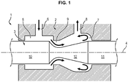
- the figure 1 illustrates an example of a valve 1 for the fuel circuit of an aircraft engine comprising a sheath 2 inside of which is a slide 3 extending along a longitudinal axis 4.
- the sleeve 2 comprises a first chamber 5 provided with a fuel inlet 6 and a second chamber 7 provided with a fuel outlet 8, the first and second chambers 5, 7 being connected to each other via a conduit 9.
- the sheath 2 further comprises two control chambers (not shown) making it possible to induce a displacement of the slide 3 along the longitudinal axis 4 as a function of a pressure differential between these two chambers.
- the drawer 3 comprises a first cylindrical part 10 extending in the first chamber 5, a second cylindrical part 11 extending in the second chamber 7 and a third part 12 connecting the first and second parts 10, 11 and at which the cross section of the drawer 3 is narrowed.
- the drawer 3 moves along the longitudinal axis 4 under the effect of a pressure differential between the two control chambers, between a closed position in which the first part 10 of the drawer 3 obstructs the conduit 9 so as to prevent the flow of fuel from the fuel inlet 6 to the fuel outlet 8, and an open position in which the first part 10 of the drawer 3 releases the duct 9 so as to allow the flow of fuel from the fuel inlet 6 to fuel outlet 8.
- the present invention addresses this problem by proposing a drawer for an aircraft engine fuel circuit valve which includes a shoulder provided with a step ensuring an arrival of the jet of fuel generated by said shoulder on a cylindrical portion of the drawer and a fuel recirculation in front of the shoulder. In this way, it avoids the generation of an axial force which would tend to move the drawer axially.
- the subject of the present invention is a slide valve for a fuel circuit valve of an aircraft engine extending along a longitudinal axis, and comprising a narrowed intermediate part extending between two cylindrical end parts, a first end part being separated from the narrowed intermediate part by a shoulder having a surface generally arranged perpendicular to the longitudinal axis, the narrowed intermediate part itself comprising, in the extension of the shoulder, at least one cylindrical portion.
- the shoulder is provided with a step which is a protrusion extending projecting from said shoulder, in the extension of the cylindrical surface of the first end part which, when fuel flows along the first end part towards the narrowed intermediate part and the second end part, ensures the generation of a jet of fuel on the cylindrical portion of the narrowed intermediate part, a fuel recirculation forming in an area in front of said shoulder.
- the step extends substantially perpendicularly from the surface of the shoulder.
- the shoulder comprises at least one groove which extends radially from the cylindrical surface of the first end part, in the direction of the longitudinal axis, up to the cylindrical portion of the narrowed intermediate part.
- This groove forms a fuel recirculation zone which ensures, when fuel flows along the first end part towards the narrowed intermediate part and the second end part, that the generated jet of fuel arrives on said cylindrical portion.
- the step extends from said groove, so as to accelerate the recirculation of the fuel in the recirculation zone.
- the groove extends longitudinally from the shoulder on the cylindrical portion of the narrowed intermediate part and the groove has, at the level of said cylindrical portion, a bottom overall. plane, the jet of fuel generated by the groove reaching said cylindrical portion at the bottom of said groove.
- this step extends substantially perpendicularly from the surface of the shoulder.
- the invention also relates to a valve for the fuel circuit of an aircraft engine, comprising a sheath, inside of which is a drawer as previously described, said sheath comprising two control chambers between which s extends the drawer and an intermediate chamber with a fuel inlet and a fuel outlet in which extends the first and second end portions and the narrowed intermediate portion of the drawer, the drawer being configured to move relatively to the sleeve under the effect of a pressure difference between the two control chambers, between a closed position in which the drawer obstructs the fuel inlet, and an open position in which the drawer releases the entry of fuel.
- the invention also relates to a fuel circuit of an aircraft turbomachine comprising a valve as previously described.
- the invention also relates to an assembly comprising an aircraft turbomachine and such a circuit, as well as an aircraft comprising a turbomachine connected to such a fuel circuit.
- the figure 2 illustrates an example of a valve 20 for an aircraft engine fuel circuit.
- the valve 20 in particular comprises a sheath 21, inside of which is a drawer 22 extending along a longitudinal axis 23.
- the sheath 21 comprises two control chambers 231, 232 making it possible to induce a displacement of the slide 22 along the longitudinal axis 23 as a function of a pressure differential between these two chambers.
- the sheath 21 further comprises an intermediate chamber formed by a first chamber 24 provided with a fuel inlet 25 and a second chamber 26 provided with a fuel outlet 27, the first and second chambers 24, 26 being connected to each other via a conduit 28.
- the slide 22 extends between the two control chambers 231, 232, in the intermediate chamber.
- the slide 22 comprises a narrowed intermediate portion 32 extending between two cylindrical end portions 29, 31, a first end portion 29 being separated from the narrowed intermediate portion 32 by a shoulder 36 having a surface 37 generally arranged perpendicularly by relative to the longitudinal axis 23.
- the narrowed intermediate portion 32 comprises, in the extension of the shoulder 36, at least one cylindrical portion 34.
- the narrowed intermediate portion 32 may also comprise a frustoconical portion 35 connecting the cylindrical portion 34 to the second end portion 31 of the drawer 22.
- the slide 22 moves along the longitudinal axis 23 under the effect of the pressure differential between the two control chambers 231, 232, between a closed position in which the first end portion 29 of the slide 22 obstructs the conduit 28 so as to prevent the flow of fuel from the inlet of fuel 25 to the fuel outlet 27, and an open position in which the first end portion 29 of the drawer 22 releases the conduit 28 so as to allow the flow of fuel from the fuel inlet 25 to the outlet fuel 27.
- the open position the sudden change in section between the first end portion 29 and the narrowed intermediate portion 32 results in the generation of a fuel jet on the narrowed intermediate portion 32.
- the shoulder 36 is provided with a step 42 extending in the extension of the cylindrical surface 30 of the first end portion 29.
- This step 42 is a protrusion projecting from the shoulder 36. It provides a recirculation of the fuel in front of the shoulder (recirculation zone 40) and thus the generation of a jet of fuel on the cylindrical portion 34 of the narrowed intermediate portion 32, when fuel flows along the first end portion 29 in the direction of the narrowed intermediate portion 32 and of the second end portion 31.
- the step 42 makes it possible to reduce the effect of the fuel pressure on the drawer 22.
- the step 42 is shown in more detail on the figure 2a .
- the step 42 extends from the shoulder 36 substantially parallel to the longitudinal axis 23. In other words, the step 42 is arranged substantially perpendicular to the shoulder 36 and to the radial surface 37 defining the latter.
- the term “substantially parallel” or “substantially perpendicular” means parallel or perpendicular to errors, that is to say to 10 °.
- the shoulder 36 comprises at least one groove 38 which extends radially from the cylindrical surface 30 of the first end portion 29, in the direction of the longitudinal axis 23, up to the cylindrical portion 34.
- the groove 38 provides recirculation of the fuel in front of the shoulder (recirculation zone 40) and thus the generation of a jet of fuel on the cylindrical portion 34 of the narrowed intermediate portion 32, when fuel flows along the first portion of end 29 towards the intermediate part narrowed 32 and the second end portion 31.
- the groove 38 makes it possible to reduce the effect of the fuel pressure on the slide 22.
- the step 42 extends from said groove 38, so as to accelerate the recirculation of the fuel in the recirculation zone 40.
- the step 42 in this case forms a protuberance preferably arranged over the entire width of the groove 38.
- the step 42 is shown in more detail on the figure 2a .
- the groove 38 comprises a surface 39 disposed generally perpendicular to the longitudinal axis 23, set back from the surface 37 of the shoulder 36 relative to the second end portion 31.
- the fuel recirculation zone 40 thus formed is positioned under the fuel jet, that is to say between the fuel jet and the spool 22.
- the fuel vortices generated at the fuel recirculation zone 40 allow to limit the angle with which the jet of fuel arrives on the narrowed intermediate portion 32, and thus to ensure that the jet of fuel arrives on the cylindrical portion 34 and not on the frustoconical portion 35 of the narrowed intermediate portion 32.
- the fuel recirculation makes it possible to reduce the effect of the fuel pressure on the slide 22.
- the jet of fuel does not apply any axial force on the cylindrical portion 34 tending to move the slide 22 longitudinally, and that in this case the only axial component applied to the slide 22 corresponds to the friction forces of the fuel. These frictional forces being negligible, the jet force is thus considerably limited.
- the fuel jet would risk reaching the frustoconical portion 35 of the narrowed intermediate portion 33, thereby generating an axial force disturbing the positioning of the drawer 22.
- the present invention tends to generate no difference in momentum between the inlet and the outlet 25, 27 of valve 20.
- the force generated by the pressure of the fuel in the recirculation zone 40 on the surface 39 of the groove 38 is limited. It is thus possible to further reduce the axial force generated on the slide 22 and in particular to compensate for the frictional forces generated by the flow of fuel on the slide 22.
- the groove 38 extends longitudinally from the shoulder 36 on the cylindrical portion 34 of the narrowed intermediate portion 32.
- the groove 38 has the effect of avoiding turbulence in the fuel flow, when the valve 20 is in position opening, and thus limit the phenomena of drawer flapping.
- the groove 38 has, at the level of the cylindrical portion 34, a generally planar bottom 41, the jet of fuel generated by the groove 38 reaching said cylindrical portion at the bottom 41 of said groove 38.
- the drawer 22 comprises for example two grooves 38 formed diametrically relative to one another.
- the groove 38 also has a connection leave 381 between the surface 39 of the groove 38 and the bottom 41 of said groove 38 configured to maintain the recirculation of the fuel in the recirculation zone 40.
- the connection leave 381 is dimensioned so as to maintain the recirculation of the fuel in the recirculation zone 40.
- the connection leave 381 facilitates the setting in motion of the fuel at the level of the recirculation zone 40 and therefore the recirculation of said fuel in said recirculation zone 40.
- the valve 20 and more specifically the drawer 22 have the advantage of reducing the jet forces which are applied to the drawer 22 by forming a recirculation zone 40 of fuel by means of the step 42 and by ensuring that the jet of fuel generated by the shoulder 36 arrives on the generally cylindrical portion 34 of the drawer 22.
- the valve 20 therefore makes it possible to prevent the flow of fuel from applying an axial force on the drawer 22.
Landscapes
- Engineering & Computer Science (AREA)
- General Engineering & Computer Science (AREA)
- Mechanical Engineering (AREA)
- Aviation & Aerospace Engineering (AREA)
- Physics & Mathematics (AREA)
- Fluid Mechanics (AREA)
- Fuel-Injection Apparatus (AREA)
- Sliding Valves (AREA)
- Valve Housings (AREA)
Description
- La présente invention concerne le domaine des vannes pour circuit de carburant d'un moteur d'aéronef du type tiroir/fourreau. Plus précisément, la présente invention concerne un tiroir pour vanne de circuit de carburant d'un moteur d'aéronef.
- La
figure 1 illustre un exemple de vanne 1 pour circuit de carburant d'un moteur d'aéronef comprenant un fourreau 2 à l'intérieur duquel est ménagé un tiroir 3 s'étendant selon un axe longitudinal 4. - Le fourreau 2 comprend une première chambre 5 munie d'une entrée de carburant 6 et d'une deuxième chambre 7 munie d'une sortie de carburant 8, la première et la deuxième chambres 5, 7 étant reliées l'une à l'autre via un conduit 9. Le fourreau 2 comprend en outre deux chambres de commande (non représentées) permettant d'induire un déplacement du tiroir 3 selon l'axe longitudinal 4 en fonction d'un différentiel de pression entre ces deux chambres.
- Le tiroir 3 comprend une première partie 10 cylindrique s'étendant dans la première chambre 5, une deuxième partie 11 cylindrique s'étendant dans la deuxième chambre 7 et une troisième partie 12 reliant les première et deuxième parties 10, 11 et au niveau de laquelle la section transversale du tiroir 3 est rétrécie. Le tiroir 3 se déplace selon l'axe longitudinal 4 sous l'effet d'un différentiel de pression entre les deux chambres de commande, entre une position de fermeture dans laquelle la première partie 10 du tiroir 3 obstrue le conduit 9 de sorte à empêcher l'écoulement de carburant depuis l'entrée de carburant 6 vers la sortie de carburant 8, et une position d'ouverture dans laquelle la première partie 10 du tiroir 3 libère le conduit 9 de sorte à autoriser l'écoulement de carburant depuis l'entrée de carburant 6 vers la sortie de carburant 8.
- Or, avec une telle vanne 1, dans la position d'ouverture, l'écoulement de carburant n'a pas la même quantité de mouvement entre l'entrée de carburant 6 et la sortie de carburant 8. En effet, la différence de section transversale entre la première partie 10 et la troisième partie 12 génère, en position d'ouverture, un jet de carburant qui vient appliquer un effort supplémentaire sur le tiroir 3. Cet effort supplémentaire, aussi appelé « force de jet », est particulièrement problématique car il comporte une composante axiale qui vient perturber le pilotage du tiroir 3 par le différentiel de pression. On comprendra en effet que tout effort axial supplémentaire s'appliquant sur le tiroir 3 entraîne une erreur dans le positionnement du tiroir 3 et génère de ce fait des imprécisions quant au débit de carburant en sortie de la deuxième chambre 7. La force de jet est donc préjudiciable au bon fonctionnement du circuit de carburant.
- Pour éviter de telles imprécisions, il est par exemple connu du document
WO 80/00870 US2015/0252908 etUS2014/0026546 . Il existe donc un besoin de limiter davantage les effets des forces de jet sur les tiroirs de circuit de carburant de moteur d'aéronef. - La présente invention répond à ce problème en proposant un tiroir pour vanne de circuit de carburant d'un moteur d'aéronef qui comprend un épaulement muni d'une marche assurant une arrivée du jet de carburant généré par ledit épaulement sur une portion cylindrique du tiroir et une recirculation du carburant devant l'épaulement. De cette façon, on évite la génération d'un effort axial qui tendrait à déplacer axialement le tiroir.
- Plus précisément, la présente invention a pour objet un tiroir pour vanne de circuit de carburant d'un moteur d'aéronef s'étendant selon un axe longitudinal, et comprenant une partie intermédiaire rétrécie s'étendant entre deux parties cylindriques d'extrémité, une première partie d'extrémité étant séparée de la partie intermédiaire rétrécie par un épaulement présentant une surface agencée globalement perpendiculairement à l'axe longitudinal, la partie intermédiaire rétrécie comportant elle-même, dans le prolongement de l'épaulement, au moins une portion cylindrique.
- L'épaulement est muni d'une marche qui est une protubérance s'étendant en saillie par rapport audit épaulement, dans le prolongement de la surface cylindrique de la première partie d'extrémité qui, lorsque du carburant s'écoule le long de la première partie d'extrémité en direction de la partie intermédiaire rétrécie et de la deuxième partie d'extrémité, assure la génération d'un jet de carburant sur la portion cylindrique de la partie intermédiaire rétrécie, une recirculation de carburant se formant dans une zone devant ledit épaulement.
- Selon un mode de réalisation, notamment la marche s'étend sensiblement perpendiculairement depuis la surface de l'épaulement.
- Selon l'invention, l'épaulement comprend au moins une rainure qui s'étend radialement depuis la surface cylindrique de la première partie d'extrémité, en direction de l'axe longitudinal, jusque la portion cylindrique de la partie intermédiaire rétrécie. Cette rainure forme une zone de recirculation de carburant qui assure, lorsque du carburant s'écoule le long de la première partie d'extrémité en direction de la partie intermédiaire rétrécie et de la deuxième partie d'extrémité, que le jet de carburant généré arrive sur ladite portion cylindrique.
- La marche s'étend à partir de ladite rainure, de sorte à accélérer la recirculation du carburant dans la zone de recirculation.
- Préférentiellement, la rainure se prolonge longitudinalement depuis l'épaulement sur la portion cylindrique de la partie intermédiaire rétrécie et la rainure présente, au niveau de ladite portion cylindrique, un fond globalement plan, le jet de carburant généré par la rainure atteignant ladite portion cylindrique au niveau du fond de ladite rainure.
- Dans un mode de réalisation, cette marche s'étend sensiblement perpendiculairement depuis la surface de l'épaulement.
- L'invention a également pour objet un vanne pour circuit de carburant d'un moteur d'aéronef, comprenant un fourreau, à l'intérieur duquel est ménagé un tiroir tel que précédemment décrit, ledit fourreau comprenant deux chambres de commande entre lesquelles s'étend le tiroir et une chambre intermédiaire munie d'une entrée de carburant et d'une sortie de carburant dans laquelle s'étend les première et deuxième parties d'extrémité et la partie intermédiaire rétrécie du tiroir, le tiroir étant configuré pour se déplacer relativement au fourreau sous l'effet d'une différence de pression entre les deux chambres de commande, entre une position de fermeture dans laquelle le tiroir obstrue l'entrée de carburant, et une position d'ouverture dans laquelle le tiroir libère l'entrée de carburant.
- L'invention a également pour objet un circuit de carburant d'une turbomachine d'aéronef comprenant une vanne telle que précédemment décrite.
- L'invention a également pour objet un ensemble comportant une turbomachine d'aéronef et un tel circuit, ainsi qu'un aéronef comprenant une turbomachine reliée à un tel circuit de carburant.
- D'autres caractéristiques, buts et avantages de la présente invention apparaitront à la lecture de la description détaillée qui va suivre, et en regard des dessins annexés donnés à titre d'exemples non limitatif et sur lesquels :
- la
figure 1 représente une vue schématique, en coupe longitudinale, d'une vanne pour circuit de carburant d'un moteur d'aéronef du type tiroir/fourreau selon l'art antérieur, - la
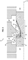
figure 2 représente une vue schématique partielle, en coupe longitudinale, d'une vanne pour circuit de carburant d'un moteur d'aéronef du type tiroir/fourreau selon un mode de réalisation de l'invention, - la
figure 2a représente une vue de détail de la vanne illustrée à lafigure 2 , - la
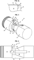
figure 3 représente une vue en perspective du tiroir de la vanne illustrée à lafigure 2 , et - la
figure 4 représente une vue de face du tiroir illustré à lafigure 3 . - La
figure 2 illustre un exemple de vanne 20 pour circuit de carburant d'un moteur d'aéronef. La vanne 20 comprend en particulier un fourreau 21, à l'intérieur duquel est ménagé un tiroir 22 s'étendant selon un axe longitudinal 23. - Le fourreau 21 comprend deux chambres de commande 231, 232 permettant d'induire un déplacement du tiroir 22 selon l'axe longitudinal 23 en fonction d'un différentiel de pression entre ces deux chambres. Le fourreau 21 comprend en outre une chambre intermédiaire formée d'une première chambre 24 munie d'une entrée de carburant 25 et d'une deuxième chambre 26 munie d'une sortie de carburant 27, la première et la deuxième chambres 24, 26 étant reliées l'une à l'autre via un conduit 28.
- Le tiroir 22 s'étend entre les deux chambres de commande 231, 232, dans la chambre intermédiaire.
- Le tiroir 22 comprend une partie intermédiaire rétrécie 32 s'étendant entre deux parties cylindriques d'extrémité 29, 31, une première partie d'extrémité 29 étant séparée de la partie intermédiaire rétrécie 32 par un épaulement 36 présentant une surface 37 agencée globalement perpendiculairement par rapport à l'axe longitudinal 23. La partie intermédiaire rétrécie 32 comporte, dans le prolongement de l'épaulement 36, au moins une portion cylindrique 34. La partie intermédiaire rétrécie 32 peut en outre comporter une portion tronconique 35 reliant la portion cylindrique 34 à la deuxième partie d'extrémité 31 du tiroir 22.
- Le tiroir 22 se déplace selon l'axe longitudinal 23 sous l'effet du différentiel de pression entre les deux chambres de commande 231, 232, entre une position de fermeture dans laquelle la première partie d'extrémité 29 du tiroir 22 obstrue le conduit 28 de sorte à empêcher l'écoulement de carburant depuis l'entrée de carburant 25 vers la sortie de carburant 27, et une position d'ouverture dans laquelle la première partie d'extrémité 29 du tiroir 22 libère le conduit 28 de sorte à autoriser l'écoulement de carburant depuis l'entrée de carburant 25 vers la sortie de carburant 27. En position d'ouverture, le changement brutal de section entre la première partie d'extrémité 29 et la partie intermédiaire rétrécie 32 entraîne la génération d'un jet de carburant sur la partie intermédiaire rétrécie 32.
- L'épaulement 36 est muni d'une marche 42 s'étendant dans le prolongement de la surface cylindrique 30 de la première partie d'extrémité 29. Cette marche 42 est une protubérance en saillie par rapport à l'épaulement 36. Elle assure une recirculation du carburant devant l'épaulement (zone de recirculation 40) et ainsi la génération d'un jet de carburant sur la portion cylindrique 34 de la partie intermédiaire rétrécie 32, lorsque du carburant s'écoule le long de la première partie d'extrémité 29 en direction de la partie intermédiaire rétrécie 32 et de la deuxième partie d'extrémité 31. La marche 42 permet de réduire l'effet de la pression du carburant sur le tiroir 22. La marche 42 est représentée plus en détail sur la
figure 2a . - La marche 42 s'étend depuis l'épaulement 36 sensiblement parallèlement à l'axe longitudinal 23. Autrement dit, la marche 42 est agencée sensiblement perpendiculairement à l'épaulement 36 et à la surface 37 radiale définissant celui-ci. On entend par « sensiblement parallèlement » ou « sensiblement perpendiculairement », parallèle ou perpendiculaire aux erreurs près, c'est-à-dire à 10° près.
- L'épaulement 36 comprend au moins une rainure 38 qui s'étend radialement depuis la surface cylindrique 30 de la première partie d'extrémité 29, en direction de l'axe longitudinal 23, jusqu'à la portion cylindrique 34. La rainure 38 assure une recirculation du carburant devant l'épaulement (zone de recirculation 40) et ainsi la génération d'un jet de carburant sur la portion cylindrique 34 de la partie intermédiaire rétrécie 32, lorsque du carburant s'écoule le long de la première partie d'extrémité 29 en direction de la partie intermédiaire rétrécie 32 et de la deuxième partie d'extrémité 31. La rainure 38 permet de réduire l'effet de la pression du carburant sur le tiroir 22.
La marche 42 s'étend à partir de ladite rainure 38, de sorte à accélérer la recirculation du carburant dans la zone de recirculation 40. La marche 42 forme dans ce cas une protubérance agencée de préférence sur toute la largeur de la rainure 38. - La marche 42 est représentée plus en détail sur la
figure 2a . - La rainure 38 comprend une surface 39 disposée globalement perpendiculairement à l'axe longitudinal 23, en retrait de la surface 37 de l'épaulement 36 par rapport à la deuxième partie d'extrémité 31.
- La zone de recirculation 40 de carburant ainsi formée est positionnée sous le jet de carburant, c'est-à-dire entre le jet de carburant et le tiroir 22. Les tourbillons de carburant générés au niveau de la zone de recirculation 40 de carburant permettent de limiter l'angle avec lequel le jet de carburant arrive sur la partie intermédiaire rétrécie 32, et ainsi de s'assurer que le jet de carburant arrive sur la portion cylindrique 34 et non sur la portion tronconique 35 de la partie intermédiaire rétrécie 32. De plus, la recirculation de carburant permet de réduire l'effet de la pression du carburant sur le tiroir 22.
- On comprendra qu'en raison de la forme cylindrique de la portion cylindrique 34, le jet de carburant n'applique sur la portion cylindrique 34 aucun effort axial tendant à déplacer longitudinalement le tiroir 22, et que dans ce cas la seule composante axiale appliquée sur le tiroir 22 correspond à des forces de frottement du carburant. Ces forces de frottement étant négligeables, la force de jet est ainsi considérablement limitée. Au contraire, sans la marche 42 et sans la zone de recirculation 40, le jet de carburant risquerait d'atteindre la portion tronconique 35 de la partie intermédiaire rétrécie 33, générant de ce fait un effort axial perturbant le positionnement du tiroir 22. Par ailleurs, contrairement à l'état de la technique qui tendait à compenser l'écart de quantité de mouvement entre l'entrée et la sortie de la vanne, la présente invention tend à ne générer aucun écart de quantité de mouvement entre l'entrée et la sortie 25, 27 de la vanne 20.
- En accélérant la recirculation de carburant dans la zone de recirculation 40, l'effort généré par la pression du carburant dans la zone de recirculation 40 sur la surface 39 de la rainure 38 est limité. Il est ainsi possible de réduire d'autant plus l'effort axial généré sur le tiroir 22 et notamment de compenser les forces de frottement générées par l'écoulement du carburant sur le tiroir 22.
- De préférence, la rainure 38 se prolonge longitudinalement depuis l'épaulement 36 sur la portion cylindrique 34 de la partie intermédiaire rétrécie 32. La rainure 38 a pour effet d'éviter les turbulences dans le flux de carburant, lorsque la vanne 20 est en position d'ouverture, et ainsi de limiter les phénomènes de battement de tiroir.
- La rainure 38 présente, au niveau de la portion cylindrique 34, un fond 41 globalement plan, le jet de carburant généré par la rainure 38 atteignant ladite portion cylindrique au niveau du fond 41 de ladite rainure 38.
- Le tiroir 22 comprend par exemple deux rainures 38 ménagées diamétralement l'une par rapport à l'autre.
- La rainure 38 présente en outre un congé de raccordement 381 entre la surface 39 de la rainure 38 et le fond 41 de ladite rainure 38 configurée pour entretenir la recirculation du carburant dans la zone de recirculation 40. Pour cela, le congé de raccordement 381 est dimensionné de sorte à entretenir la recirculation du carburant dans la zone de recirculation 40. Le congé de raccordement 381 facilite la mise en mouvement du carburant au niveau de la zone de recirculation 40 et donc la recirculation dudit carburant dans ladite zone de recirculation 40.
- La vanne 20 et plus spécifiquement le tiroir 22 présentent l'avantage de réduire les forces de jet qui s'appliquent sur le tiroir 22 en formant une zone de recirculation 40 de carburant au moyen de la marche 42 et en s'assurant que le jet de carburant généré par l'épaulement 36 arrive sur la portion globalement cylindrique 34 du tiroir 22. La vanne 20 permet donc d'éviter que l'écoulement du carburant applique un effort axial sur le tiroir 22.
Claims (7)
- Tiroir (22) pour vanne de circuit de carburant (20) d'un moteur d'aéronef s'étendant selon un axe longitudinal (23), et comprenant une partie intermédiaire rétrécie (32) s'étendant entre deux parties cylindriques d'extrémité (29, 31), une première partie d'extrémité (29) étant séparée de la partie intermédiaire rétrécie (32) par un épaulement (36) présentant une surface (37) agencée globalement perpendiculairement à l'axe longitudinal (23), la partie intermédiaire rétrécie (32) comportant elle-même, dans le prolongement de l'épaulement (36), au moins une portion cylindrique (34),
l'épaulement (36) étant muni d'une marche (42) qui est une protubérance s'étendant en saillie par rapport audit épaulement, dans le prolongement de la surface cylindrique (30) de la première partie d'extrémité (29) et qui, lorsque du carburant s'écoule le long de la première partie d'extrémité (29) en direction de la partie intermédiaire rétrécie (32) et de la deuxième partie d'extrémité (31), assure la génération d'un jet de carburant sur la portion cylindrique (34) de la partie intermédiaire rétrécie (32), une recirculation de carburant se formant dans une zone (40) adjacente audit épaulement (36), le tiroir étant caractérisé en ce que l'épaulement (36) comprend au moins une rainure (38) qui s'étend radialement depuis la surface cylindrique (30) de la première partie d'extrémité (29), en direction de l'axe longitudinal (23), jusqu'à la portion cylindrique (34), et à partir de laquelle s'étend la marche (42), de sorte à accélérer la recirculation du carburant dans la zone de recirculation (40). - Tiroir (22) selon la revendication 1, dans lequel la marche (42) s'étend sensiblement perpendiculairement depuis la surface (37) de l'épaulement (36).
- Tiroir (22) selon la revendication 1, dans lequel la rainure (38) se prolonge longitudinalement depuis l'épaulement (36) sur la portion cylindrique (34) de la partie intermédiaire rétrécie (32) et dans lequel la rainure (38) présente, au niveau de ladite portion cylindrique, un fond (41) globalement plan, le jet de carburant généré par la rainure (38) atteignant ladite portion cylindrique au niveau du fond (41) de ladite rainure (38).
- Vanne (20) pour circuit de carburant d'un moteur d'aéronef, comprenant un fourreau (21) à l'intérieur duquel est ménagé un tiroir (22) selon l'une quelconque des revendications 1 à 3, ledit fourreau (21) comprenant deux chambres de commande (231, 232) entre lesquelles s'étend le tiroir (22) et une chambre intermédiaire munie d'une entrée de carburant (25) et d'une sortie de carburant (27) dans laquelle s'étend les première et deuxième parties d'extrémité (29, 31) et la partie intermédiaire rétrécie (32) du tiroir (22), le tiroir (22) étant configuré pour se déplacer relativement au fourreau (21) sous l'effet d'une différence de pression entre les deux chambres de commande (231, 232), entre une position de fermeture dans laquelle le tiroir (22) obstrue l'entrée de carburant (25), et une position d'ouverture dans laquelle le tiroir libère l'entrée de carburant (25).
- Circuit de carburant de turbomachine d'aéronef comprenant une vanne (20) selon la revendication 4.
- Ensemble comportant une turbomachine d'aéronef et un circuit de carburant selon la revendication 5.
- Aéronef comprenant une turbomachine reliée à un circuit de carburant selon la revendication 5.
Applications Claiming Priority (2)
| Application Number | Priority Date | Filing Date | Title |
|---|---|---|---|
| FR1653520A FR3050509B1 (fr) | 2016-04-21 | 2016-04-21 | Tiroir pour vanne de circuit de carburant d'un moteur d'aeronef |
| PCT/FR2017/050939 WO2017182758A1 (fr) | 2016-04-21 | 2017-04-20 | Tiroir pour vanne de circuit de carburant d'un moteur d'aeronef |
Publications (2)
| Publication Number | Publication Date |
|---|---|
| EP3446008A1 EP3446008A1 (fr) | 2019-02-27 |
| EP3446008B1 true EP3446008B1 (fr) | 2020-01-22 |
Family
ID=56148505
Family Applications (1)
| Application Number | Title | Priority Date | Filing Date |
|---|---|---|---|
| EP17725297.0A Active EP3446008B1 (fr) | 2016-04-21 | 2017-04-20 | Tiroir pour vanne de circuit de carburant d'un moteur d'aeronef |
Country Status (5)
| Country | Link |
|---|---|
| US (1) | US10690264B2 (fr) |
| EP (1) | EP3446008B1 (fr) |
| CN (1) | CN109073101B (fr) |
| FR (1) | FR3050509B1 (fr) |
| WO (1) | WO2017182758A1 (fr) |
Families Citing this family (3)
| Publication number | Priority date | Publication date | Assignee | Title |
|---|---|---|---|---|
| FR3050508B1 (fr) * | 2016-04-21 | 2018-10-05 | Safran Aircraft Engines | Tiroir pour vanne de circuit de carburant d'un moteur d'aeronef |
| DE102018102397A1 (de) * | 2018-02-02 | 2019-08-08 | J.D. Neuhaus Holding Gmbh & Co. Kg | Steuerventilanordnung zur indirekten pneumatischen Steuerung |
| CN111637106A (zh) * | 2020-05-15 | 2020-09-08 | 大连理工大学 | 一种降低多路阀稳态液动力的环形凸台 |
Family Cites Families (15)
| Publication number | Priority date | Publication date | Assignee | Title |
|---|---|---|---|---|
| US3556155A (en) * | 1969-01-24 | 1971-01-19 | Caterpillar Tractor Co | Variable flow-modulated valve |
| US3630230A (en) * | 1969-10-21 | 1971-12-28 | Schneider Co Optische Werke | Fluid valve with controlled axial thrust |
| US4009864A (en) * | 1975-02-04 | 1977-03-01 | Caterpillar Tractor Co. | Throttling slot configuration for a valve spool |
| GB1510418A (en) * | 1976-03-08 | 1978-05-10 | Caterpillar Tractor Co | Fluid control valve |
| DE3119101A1 (de) * | 1981-05-14 | 1982-12-02 | Mannesmann Rexroth GmbH, 8770 Lohr | "wegeventil" |
| US4941508A (en) * | 1989-12-28 | 1990-07-17 | Dana Corporation | Force balanced hydraulic spool valve |
| US6397890B1 (en) * | 1999-02-15 | 2002-06-04 | Case Corp. | Variable metering fluid control valve |
| US6450194B1 (en) * | 2000-09-26 | 2002-09-17 | Case Corporation | Spool notch geometry for hydraulic spool valve |
| CN2533352Y (zh) * | 2002-04-05 | 2003-01-29 | 上海中茂新能源应用有限公司 | 轻烃汽油两用燃料汽车燃料转换阀 |
| KR100496650B1 (ko) * | 2002-06-27 | 2005-06-22 | 주식회사 한화 | 유동력 보상이 가능한 스풀 밸브 및 이를 이용한 유압밸브, 공압 밸브, 3웨이 제어 밸브, 4웨이 제어 밸브 |
| US6682016B1 (en) * | 2002-09-05 | 2004-01-27 | Hamilton Sundstrand | Thermal management valve with drop-tight shutoff of return to tank |
| US7093607B2 (en) * | 2004-03-23 | 2006-08-22 | Hr Textron, Inc. | Methods and apparatus for maintaining pressure gain in a servovalve assembly |
| US20140026546A1 (en) * | 2012-07-25 | 2014-01-30 | Caterpillar, Inc. | Regeneration Valve for a Hydraulic Circuit |
| JP2015169212A (ja) * | 2014-03-04 | 2015-09-28 | 株式会社デンソー | 流体制御弁 |
| FR3050508B1 (fr) * | 2016-04-21 | 2018-10-05 | Safran Aircraft Engines | Tiroir pour vanne de circuit de carburant d'un moteur d'aeronef |
-
2016
- 2016-04-21 FR FR1653520A patent/FR3050509B1/fr active Active
-
2017
- 2017-04-20 US US16/095,187 patent/US10690264B2/en active Active
- 2017-04-20 CN CN201780024977.9A patent/CN109073101B/zh active Active
- 2017-04-20 EP EP17725297.0A patent/EP3446008B1/fr active Active
- 2017-04-20 WO PCT/FR2017/050939 patent/WO2017182758A1/fr not_active Ceased
Non-Patent Citations (1)
| Title |
|---|
| None * |
Also Published As
| Publication number | Publication date |
|---|---|
| US10690264B2 (en) | 2020-06-23 |
| FR3050509A1 (fr) | 2017-10-27 |
| US20190137004A1 (en) | 2019-05-09 |
| FR3050509B1 (fr) | 2018-04-06 |
| CN109073101A (zh) | 2018-12-21 |
| EP3446008A1 (fr) | 2019-02-27 |
| WO2017182758A1 (fr) | 2017-10-26 |
| CN109073101B (zh) | 2020-03-10 |
Similar Documents
| Publication | Publication Date | Title |
|---|---|---|
| FR2954447A1 (fr) | Electrovanne et installation d'assistance de conduite equipee d'au moins une telle electrovanne | |
| EP3638936B1 (fr) | Gicleur de fluide axial a clapet evente | |
| EP2480774B1 (fr) | Doseur de carburant ayant un dispositif de regulation ameliore | |
| EP3446009B1 (fr) | Vanne de circuit de carburant d'un moteur d'aéronef | |
| EP2683930A1 (fr) | Injecteur pour le mélange de deux ergols comprenant au moins un élément d'injection a structure tricoaxiale | |
| EP3446008A1 (fr) | Tiroir pour vanne de circuit de carburant d'un moteur d'aeronef | |
| WO2017207902A1 (fr) | Chambre entre un embout d'entree et un obturateur, pour injecteur de turbomachine | |
| EP2143929B1 (fr) | Motor-fusée comprenant un dispositif d'injection de monoergol à débit modulable avec vitesse d'injection stable | |
| EP1312864B1 (fr) | Dispositif doseur de combustible pour injecteur de turbomachine | |
| EP2910767B1 (fr) | Injecteur de carburant | |
| FR3001001A1 (fr) | Soupape de regulation de pression d'accumulateur de carburant haute pression | |
| FR2775048A1 (fr) | Valve commandant le passage d'un gaz en fonction de sa pression | |
| EP2808532B1 (fr) | Injecteur de carburant | |
| EP4065892B1 (fr) | Système d'injection d'air et de carburant d'une turbomachine, chambre de combustion comprenant un tel système et turbomachine associée | |
| EP3253961B1 (fr) | Vanne de commande pour injecteur de carburant | |
| EP1426610B1 (fr) | Dispositif d'amortissement des ondes de pression pour système d'injection de carburant | |
| EP3027884B1 (fr) | Agencement intégré d'une vanne haute pression et d'une rampe d'injection | |
| EP2846033B1 (fr) | Valve de commande d'injecteur de carburant pour rampe d'injection commune et injecteur correspondant | |
| FR2752902A1 (fr) | Vanne, notamment pour la regulation d'une installation de distribution d'eau potable | |
| FR3061935A1 (fr) | Regulateur de pression pour une rampe commune d'une installation d'injection haute pression | |
| FR2848256A1 (fr) | Dispositif d'amortissement des ondes de pression pour systeme d'injection de carburant | |
| FR2877052A1 (fr) | Tuyere a section variable de turbomachine a support de levier de commande monobloc | |
| FR2705424A1 (fr) | Clapet anti retour avec limiteur de débit. | |
| FR3080891A1 (fr) | Injecteur de carburant pour moteur a combustion interne | |
| FR2857418A1 (fr) | Dispositif d'application de precontrainte a une soupape d'un injecteur de carburant et moyens de rupture d'impedance acoustique de l'injecteur |
Legal Events
| Date | Code | Title | Description |
|---|---|---|---|
| STAA | Information on the status of an ep patent application or granted ep patent |
Free format text: STATUS: UNKNOWN |
|
| STAA | Information on the status of an ep patent application or granted ep patent |
Free format text: STATUS: THE INTERNATIONAL PUBLICATION HAS BEEN MADE |
|
| PUAI | Public reference made under article 153(3) epc to a published international application that has entered the european phase |
Free format text: ORIGINAL CODE: 0009012 |
|
| STAA | Information on the status of an ep patent application or granted ep patent |
Free format text: STATUS: REQUEST FOR EXAMINATION WAS MADE |
|
| 17P | Request for examination filed |
Effective date: 20181023 |
|
| AK | Designated contracting states |
Kind code of ref document: A1 Designated state(s): AL AT BE BG CH CY CZ DE DK EE ES FI FR GB GR HR HU IE IS IT LI LT LU LV MC MK MT NL NO PL PT RO RS SE SI SK SM TR |
|
| AX | Request for extension of the european patent |
Extension state: BA ME |
|
| DAV | Request for validation of the european patent (deleted) | ||
| DAX | Request for extension of the european patent (deleted) | ||
| GRAP | Despatch of communication of intention to grant a patent |
Free format text: ORIGINAL CODE: EPIDOSNIGR1 |
|
| STAA | Information on the status of an ep patent application or granted ep patent |
Free format text: STATUS: GRANT OF PATENT IS INTENDED |
|
| INTG | Intention to grant announced |
Effective date: 20190823 |
|
| GRAS | Grant fee paid |
Free format text: ORIGINAL CODE: EPIDOSNIGR3 |
|
| GRAA | (expected) grant |
Free format text: ORIGINAL CODE: 0009210 |
|
| STAA | Information on the status of an ep patent application or granted ep patent |
Free format text: STATUS: THE PATENT HAS BEEN GRANTED |
|
| AK | Designated contracting states |
Kind code of ref document: B1 Designated state(s): AL AT BE BG CH CY CZ DE DK EE ES FI FR GB GR HR HU IE IS IT LI LT LU LV MC MK MT NL NO PL PT RO RS SE SI SK SM TR |
|
| REG | Reference to a national code |
Ref country code: GB Ref legal event code: FG4D Free format text: NOT ENGLISH |
|
| REG | Reference to a national code |
Ref country code: CH Ref legal event code: EP |
|
| REG | Reference to a national code |
Ref country code: DE Ref legal event code: R096 Ref document number: 602017010983 Country of ref document: DE |
|
| REG | Reference to a national code |
Ref country code: AT Ref legal event code: REF Ref document number: 1227109 Country of ref document: AT Kind code of ref document: T Effective date: 20200215 |
|
| REG | Reference to a national code |
Ref country code: IE Ref legal event code: FG4D Free format text: LANGUAGE OF EP DOCUMENT: FRENCH |
|
| REG | Reference to a national code |
Ref country code: SE Ref legal event code: TRGR |
|
| REG | Reference to a national code |
Ref country code: NL Ref legal event code: MP Effective date: 20200122 |
|
| REG | Reference to a national code |
Ref country code: LT Ref legal event code: MG4D |
|
| PG25 | Lapsed in a contracting state [announced via postgrant information from national office to epo] |
Ref country code: RS Free format text: LAPSE BECAUSE OF FAILURE TO SUBMIT A TRANSLATION OF THE DESCRIPTION OR TO PAY THE FEE WITHIN THE PRESCRIBED TIME-LIMIT Effective date: 20200122 Ref country code: FI Free format text: LAPSE BECAUSE OF FAILURE TO SUBMIT A TRANSLATION OF THE DESCRIPTION OR TO PAY THE FEE WITHIN THE PRESCRIBED TIME-LIMIT Effective date: 20200122 Ref country code: NO Free format text: LAPSE BECAUSE OF FAILURE TO SUBMIT A TRANSLATION OF THE DESCRIPTION OR TO PAY THE FEE WITHIN THE PRESCRIBED TIME-LIMIT Effective date: 20200422 Ref country code: PT Free format text: LAPSE BECAUSE OF FAILURE TO SUBMIT A TRANSLATION OF THE DESCRIPTION OR TO PAY THE FEE WITHIN THE PRESCRIBED TIME-LIMIT Effective date: 20200614 Ref country code: NL Free format text: LAPSE BECAUSE OF FAILURE TO SUBMIT A TRANSLATION OF THE DESCRIPTION OR TO PAY THE FEE WITHIN THE PRESCRIBED TIME-LIMIT Effective date: 20200122 |
|
| PG25 | Lapsed in a contracting state [announced via postgrant information from national office to epo] |
Ref country code: LV Free format text: LAPSE BECAUSE OF FAILURE TO SUBMIT A TRANSLATION OF THE DESCRIPTION OR TO PAY THE FEE WITHIN THE PRESCRIBED TIME-LIMIT Effective date: 20200122 Ref country code: IS Free format text: LAPSE BECAUSE OF FAILURE TO SUBMIT A TRANSLATION OF THE DESCRIPTION OR TO PAY THE FEE WITHIN THE PRESCRIBED TIME-LIMIT Effective date: 20200522 Ref country code: BG Free format text: LAPSE BECAUSE OF FAILURE TO SUBMIT A TRANSLATION OF THE DESCRIPTION OR TO PAY THE FEE WITHIN THE PRESCRIBED TIME-LIMIT Effective date: 20200422 Ref country code: HR Free format text: LAPSE BECAUSE OF FAILURE TO SUBMIT A TRANSLATION OF THE DESCRIPTION OR TO PAY THE FEE WITHIN THE PRESCRIBED TIME-LIMIT Effective date: 20200122 Ref country code: GR Free format text: LAPSE BECAUSE OF FAILURE TO SUBMIT A TRANSLATION OF THE DESCRIPTION OR TO PAY THE FEE WITHIN THE PRESCRIBED TIME-LIMIT Effective date: 20200423 |
|
| REG | Reference to a national code |
Ref country code: DE Ref legal event code: R097 Ref document number: 602017010983 Country of ref document: DE |
|
| PG25 | Lapsed in a contracting state [announced via postgrant information from national office to epo] |
Ref country code: LT Free format text: LAPSE BECAUSE OF FAILURE TO SUBMIT A TRANSLATION OF THE DESCRIPTION OR TO PAY THE FEE WITHIN THE PRESCRIBED TIME-LIMIT Effective date: 20200122 Ref country code: SM Free format text: LAPSE BECAUSE OF FAILURE TO SUBMIT A TRANSLATION OF THE DESCRIPTION OR TO PAY THE FEE WITHIN THE PRESCRIBED TIME-LIMIT Effective date: 20200122 Ref country code: EE Free format text: LAPSE BECAUSE OF FAILURE TO SUBMIT A TRANSLATION OF THE DESCRIPTION OR TO PAY THE FEE WITHIN THE PRESCRIBED TIME-LIMIT Effective date: 20200122 Ref country code: DK Free format text: LAPSE BECAUSE OF FAILURE TO SUBMIT A TRANSLATION OF THE DESCRIPTION OR TO PAY THE FEE WITHIN THE PRESCRIBED TIME-LIMIT Effective date: 20200122 Ref country code: SK Free format text: LAPSE BECAUSE OF FAILURE TO SUBMIT A TRANSLATION OF THE DESCRIPTION OR TO PAY THE FEE WITHIN THE PRESCRIBED TIME-LIMIT Effective date: 20200122 Ref country code: ES Free format text: LAPSE BECAUSE OF FAILURE TO SUBMIT A TRANSLATION OF THE DESCRIPTION OR TO PAY THE FEE WITHIN THE PRESCRIBED TIME-LIMIT Effective date: 20200122 Ref country code: RO Free format text: LAPSE BECAUSE OF FAILURE TO SUBMIT A TRANSLATION OF THE DESCRIPTION OR TO PAY THE FEE WITHIN THE PRESCRIBED TIME-LIMIT Effective date: 20200122 Ref country code: CZ Free format text: LAPSE BECAUSE OF FAILURE TO SUBMIT A TRANSLATION OF THE DESCRIPTION OR TO PAY THE FEE WITHIN THE PRESCRIBED TIME-LIMIT Effective date: 20200122 |
|
| REG | Reference to a national code |
Ref country code: AT Ref legal event code: MK05 Ref document number: 1227109 Country of ref document: AT Kind code of ref document: T Effective date: 20200122 |
|
| PLBE | No opposition filed within time limit |
Free format text: ORIGINAL CODE: 0009261 |
|
| STAA | Information on the status of an ep patent application or granted ep patent |
Free format text: STATUS: NO OPPOSITION FILED WITHIN TIME LIMIT |
|
| PG25 | Lapsed in a contracting state [announced via postgrant information from national office to epo] |
Ref country code: MC Free format text: LAPSE BECAUSE OF FAILURE TO SUBMIT A TRANSLATION OF THE DESCRIPTION OR TO PAY THE FEE WITHIN THE PRESCRIBED TIME-LIMIT Effective date: 20200122 |
|
| REG | Reference to a national code |
Ref country code: CH Ref legal event code: PL |
|
| 26N | No opposition filed |
Effective date: 20201023 |
|
| PG25 | Lapsed in a contracting state [announced via postgrant information from national office to epo] |
Ref country code: LI Free format text: LAPSE BECAUSE OF NON-PAYMENT OF DUE FEES Effective date: 20200430 Ref country code: CH Free format text: LAPSE BECAUSE OF NON-PAYMENT OF DUE FEES Effective date: 20200430 Ref country code: AT Free format text: LAPSE BECAUSE OF FAILURE TO SUBMIT A TRANSLATION OF THE DESCRIPTION OR TO PAY THE FEE WITHIN THE PRESCRIBED TIME-LIMIT Effective date: 20200122 Ref country code: LU Free format text: LAPSE BECAUSE OF NON-PAYMENT OF DUE FEES Effective date: 20200420 |
|
| REG | Reference to a national code |
Ref country code: BE Ref legal event code: MM Effective date: 20200430 |
|
| PG25 | Lapsed in a contracting state [announced via postgrant information from national office to epo] |
Ref country code: SI Free format text: LAPSE BECAUSE OF FAILURE TO SUBMIT A TRANSLATION OF THE DESCRIPTION OR TO PAY THE FEE WITHIN THE PRESCRIBED TIME-LIMIT Effective date: 20200122 Ref country code: BE Free format text: LAPSE BECAUSE OF NON-PAYMENT OF DUE FEES Effective date: 20200430 Ref country code: PL Free format text: LAPSE BECAUSE OF FAILURE TO SUBMIT A TRANSLATION OF THE DESCRIPTION OR TO PAY THE FEE WITHIN THE PRESCRIBED TIME-LIMIT Effective date: 20200122 |
|
| PG25 | Lapsed in a contracting state [announced via postgrant information from national office to epo] |
Ref country code: IE Free format text: LAPSE BECAUSE OF NON-PAYMENT OF DUE FEES Effective date: 20200420 |
|
| PG25 | Lapsed in a contracting state [announced via postgrant information from national office to epo] |
Ref country code: TR Free format text: LAPSE BECAUSE OF FAILURE TO SUBMIT A TRANSLATION OF THE DESCRIPTION OR TO PAY THE FEE WITHIN THE PRESCRIBED TIME-LIMIT Effective date: 20200122 Ref country code: MT Free format text: LAPSE BECAUSE OF FAILURE TO SUBMIT A TRANSLATION OF THE DESCRIPTION OR TO PAY THE FEE WITHIN THE PRESCRIBED TIME-LIMIT Effective date: 20200122 Ref country code: CY Free format text: LAPSE BECAUSE OF FAILURE TO SUBMIT A TRANSLATION OF THE DESCRIPTION OR TO PAY THE FEE WITHIN THE PRESCRIBED TIME-LIMIT Effective date: 20200122 |
|
| PG25 | Lapsed in a contracting state [announced via postgrant information from national office to epo] |
Ref country code: MK Free format text: LAPSE BECAUSE OF FAILURE TO SUBMIT A TRANSLATION OF THE DESCRIPTION OR TO PAY THE FEE WITHIN THE PRESCRIBED TIME-LIMIT Effective date: 20200122 Ref country code: AL Free format text: LAPSE BECAUSE OF FAILURE TO SUBMIT A TRANSLATION OF THE DESCRIPTION OR TO PAY THE FEE WITHIN THE PRESCRIBED TIME-LIMIT Effective date: 20200122 |
|
| PGFP | Annual fee paid to national office [announced via postgrant information from national office to epo] |
Ref country code: DE Payment date: 20250417 Year of fee payment: 9 |
|
| PGFP | Annual fee paid to national office [announced via postgrant information from national office to epo] |
Ref country code: IT Payment date: 20250430 Year of fee payment: 9 |
|
| PGFP | Annual fee paid to national office [announced via postgrant information from national office to epo] |
Ref country code: FR Payment date: 20250422 Year of fee payment: 9 |
|
| PGFP | Annual fee paid to national office [announced via postgrant information from national office to epo] |
Ref country code: SE Payment date: 20250423 Year of fee payment: 9 |
|
| PGFP | Annual fee paid to national office [announced via postgrant information from national office to epo] |
Ref country code: GB Payment date: 20260327 Year of fee payment: 10 |