EP3446037B1 - Flüssigkeitsverbrennungsvorrichtung - Google Patents
Flüssigkeitsverbrennungsvorrichtung Download PDFInfo
- Publication number
- EP3446037B1 EP3446037B1 EP17719892.6A EP17719892A EP3446037B1 EP 3446037 B1 EP3446037 B1 EP 3446037B1 EP 17719892 A EP17719892 A EP 17719892A EP 3446037 B1 EP3446037 B1 EP 3446037B1
- Authority
- EP
- European Patent Office
- Prior art keywords
- flow
- air
- fuel
- air inlet
- combustion device
- Prior art date
- Legal status (The legal status is an assumption and is not a legal conclusion. Google has not performed a legal analysis and makes no representation as to the accuracy of the status listed.)
- Active
Links
Images


Classifications
-
- F—MECHANICAL ENGINEERING; LIGHTING; HEATING; WEAPONS; BLASTING
- F23—COMBUSTION APPARATUS; COMBUSTION PROCESSES
- F23G—CREMATION FURNACES; CONSUMING WASTE PRODUCTS BY COMBUSTION
- F23G7/00—Incinerators or other apparatus for consuming industrial waste, e.g. chemicals
- F23G7/06—Incinerators or other apparatus for consuming industrial waste, e.g. chemicals of waste gases or noxious gases, e.g. exhaust gases
- F23G7/08—Incinerators or other apparatus for consuming industrial waste, e.g. chemicals of waste gases or noxious gases, e.g. exhaust gases using flares, e.g. in stacks
- F23G7/085—Incinerators or other apparatus for consuming industrial waste, e.g. chemicals of waste gases or noxious gases, e.g. exhaust gases using flares, e.g. in stacks in stacks
-
- F—MECHANICAL ENGINEERING; LIGHTING; HEATING; WEAPONS; BLASTING
- F23—COMBUSTION APPARATUS; COMBUSTION PROCESSES
- F23D—BURNERS
- F23D14/00—Burners for combustion of a gas, e.g. of a gas stored under pressure as a liquid
- F23D14/46—Details
- F23D14/72—Safety devices, e.g. operative in case of failure of gas supply
- F23D14/82—Preventing flashback or blowback
-
- F—MECHANICAL ENGINEERING; LIGHTING; HEATING; WEAPONS; BLASTING
- F23—COMBUSTION APPARATUS; COMBUSTION PROCESSES
- F23G—CREMATION FURNACES; CONSUMING WASTE PRODUCTS BY COMBUSTION
- F23G2208/00—Safety aspects
- F23G2208/10—Preventing or abating fire or explosion, e.g. by purging
-
- F—MECHANICAL ENGINEERING; LIGHTING; HEATING; WEAPONS; BLASTING
- F23—COMBUSTION APPARATUS; COMBUSTION PROCESSES
- F23G—CREMATION FURNACES; CONSUMING WASTE PRODUCTS BY COMBUSTION
- F23G2209/00—Specific waste
- F23G2209/14—Gaseous waste or fumes
Definitions
- This invention relates generally to a fluid combustion device for use in flaring. More specifically, although not exclusively, this invention relates to fluid combustion devices for use in flare pilots or gas flares or flare stacks and to methods for operating such devices. Even more specifically, although not exclusively, this invention relates to flame front generators for use in flare pilots.
- Flare systems 1' which commonly include flare stacks 2' and a fluid combustion device 3' such as a flare pilot 30' (as shown in Figure 1 ), find use in many gas processing facilities as a means to safely dispose of undesirable gases. These gases may be in the form of flammable and/or combustible waste gas streams and may be continuously vented or may be collected from one or more sources prior to disposal via a system of relief valves, blowdown valves and/or control valves.
- Flare stacks 2' are upwardly directed ducts designed for the disposal by burning of the unwanted quantities of flammable and/or combustible gases and are commonly used in process industries, e.g. the petroleum industry. Flare stacks 2' typically have a first end 21' which is open to the atmosphere and a second end (not shown) which is connected to the source of flammable and/or combustible gases.
- a typical condition of operation is one in which the quantity of gas required to be disposed of varies greatly over time and/or is discontinuous.
- Flare stacks 2' typically provide a relatively elevated location for the combustion of such emissions, for example 30m or more above ground level, such that heat generated by said combustion is spaced from ground level (where personnel and/or other equipment may be located).
- the pilot flame PF' is commonly generated by a flare pilot 30', in which a continuous flow of gaseous fuel, e.g. natural gas or plant gas, is provided through a supply conduit 5'.
- gaseous fuel e.g. natural gas or plant gas
- the supply conduit 5' is connected to a pilot tip 61' by a pilot mixer 6b' and a downstream conduit 6'.
- Air is supplied via an air intake 7' and mixed with the fuel flow in a pilot mixer 6b', the fuel and air mixture then flowing through the downstream conduit 6' and being ignited adjacent the pilot tip 61', thereby generating a continuous pilot flame PF' at the pilot tip 61'.
- Flare pilots 30' are known in which air is continuously supplied at pressure thereto, e.g. in the form of compressed air. However, if the supply of such pressurised air is interrupted or stopped the pilot flame PF' may be extinguished.
- Other flare pilots 30' are known in which air is self-inspirated, e.g. entrained, by the flow of fuel within the flare pilots 30'.
- pilot flames PF' may be susceptible to being extinguished, for example under the influence of strong winds or other environmental conditions or by a reduction or interruption in the supply of fuel and/or air.
- pilot flames PF' may be susceptible to being extinguished, for example under the influence of strong winds or other environmental conditions or by a reduction or interruption in the supply of fuel and/or air.
- FIG 1 Only one flare pilot 30' is shown in Figure 1 it will be appreciated by one skilled in the art that in practice multiple such flare pilots 30' may be disposed, generally at regularly spaced intervals, around the flare stack 2'. Multiple such flare pilots 30' are commonly provided in an attempt to mitigate against the possibility of extinguishment of pilot flames PF'.
- each flare pilot 30' is typically provided with an ignition means 4' which is designed to reliably reignite a pilot flame PF' should such a flame be extinguished, where reignition should typically be achievable even during a power failure and should be achievable independently of any other flare pilots 30' (if present).
- ignition means 4' are generally operable remotely from a generated pilot flame PF'.
- One such ignition means 4' may be a spark ignition, located adjacent or interior to the pilot tip 61' of a flare pilot 30'.
- a further ignition means 4' is a flame front generator 3" (as shown in Figure 2 ) which is a fluid combustion device 3".
- a flame front generator 3" typically includes a supply conduit 5" providing a non-continuous flow of fuel to which air is supplied, via an air intake 7", and is mixed in a mixing chamber 6b". Downstream of the mixing chamber 6b" the fuel and air mixture is ignited, for example via an ignition means such as a spark generator 41", in order to generate a flame front which travels along a downstream conduit 6" to a distal end 61" thereof.
- the distal end 61" of the flame front generator 3" is typically disposed adjacent a pilot tip of a flare pilot 30".
- the air may be supplied at pressure, e.g. in the form of compressed air, or may be self-inspirated, e.g. entrained, into the fuel flow.
- the flame front upon reaching the distal end 61" ignites or reignites a pilot flame PF" of the flare pilot 30".
- the air intake 7", mixing chamber 6b" and/or spark generator 41" are typically located at or about ground level, thereby enabling ease of manual operation and/or maintenance.
- Flame front generators 3" are known to suffer from a propensity to form moisture within the downstream conduit 6" which can lead to corrosion of said conduit 6".
- a flame front generated by a known flame front generator 3" may be extinguished within the downstream conduit 6" prior to reaching the distal end 61" thereof, hence failing to ignite or reignite a pilot flame PF". Extinguishment may be caused by accumulated moisture within the downstream conduit 6".
- Such an occurrence may result in the continuous supply of fuel from a flare pilot 30" failing to combust and hence generating a potentially hazardous mass of fuel in the vicinity of a flare stack 2' (and any equipment or personnel thereabout).
- any emission of gas through a flare stack 2' may not be ignited, due to the absence of a pilot flame PF", which may therefore generate a potentially hazardous mass of said emitted gas in the vicinity of the flare stack 2' (and any equipment or personnel thereabout).
- pilot flame PF pilot flame
- the flame front may travel back along the downstream conduit 6", consuming the fuel retained therein. Furthermore, the flame front may travel back from the ignition means 41' toward the air intake 7", for example when the velocity of the flame front exceeds the velocity of the fuel within the flame front generator 3". Such an occurrence is commonly known as flashback.
- the flame front may propagate along the downstream conduit 6" by deflagration and/or detonation.
- the flame propagation will typically start as a deflagration.
- the deflagration is characterised by combustion occurring behind the pressure wave with the expansion of the combustion products driving the flame front forwards.
- Turbulence leads to faster mass transport and increases the surface area of material, e.g. gas (for example natural gas or plant gas), to burn which, in turn, leads to rapid flame acceleration and possibly the formation of shock waves ahead of the flame front. In certain circumstances, this can lead to the deflagration transitioning into a detonation.
- Both deflagration and detonation cause damage to the conduit and/or equipment through which they travel and may additionally result in damage to and/or failure of adjacent structures.
- this damage may be catastrophic and entail danger to personnel as well as structures and/or equipment, for example if the deflagration or detonation reaches the air intake 7", mixing chamber 6b" and/or spark generator 41" which may be located at or about ground level.
- a flame front propagating by means of a deflagration travels through unburnt material, for example fuel or a fuel and air mixture, at subsonic speeds.
- a flame front propagating by means of a detonation travels through unburnt material, e.g. fuel or a fuel and air mixture, at supersonic speeds, the shock wave associated with detonation and the flame front being coupled or superimposed.
- detonations are capable of causing more damage than are deflagrations. Therefore, it is particularly important to protect against flashback detonation. It is also important to protect against flashback deflagration.
- US Patent 4,248,585 discloses an igniter for a flare stack for waste gases where a fuel gas for ignition aspirates combustion air through openings in a housing enclosing a supply line for the fuel gas.
- US Patent 4,025,281 discloses apparatus for flaring combustible waste gases including a vertical flare stack.
- a first aspect of the invention provides a fluid combustion device, in accordance with Claim 1.
- the fluid combustion device may be attached or attachable, e.g. associated or associable, at or adjacent an or the upper or open end of a flare stack.
- the or each air inlet surrounds the primary flow axis or path and/or the flow conduit.
- the or each air inlet surrounds and/or is concentric with the primary flow axis or path and/or the flow conduit.
- the or each air inlet may be disposed symmetrically or substantially symmetrically about the primary flow axis or path. It will be appreciated that a single, continuous, air inlet may include more orders of symmetry than plural air inlets, particularly if said continuous air inlet is concentric with the primary flow axis or path and/or the flow conduit.
- each air inlet may be positioned or arranged at evenly spaced locations circumferentially around the primary flow axis or path and/or the flow conduit.
- the plural air inlets may be positioned or arranged at non-evenly spaced locations circumferentially around the primary flow axis or path and/or the flow conduit.
- one or more of the plural air inlets may be located or positioned upstream or downstream of the other air inlet(s).
- the flow area of the flow conduit may increase or decrease at, adjacent or upstream of the air inlet or inlets, for example to encourage air to be entrained, in use, into a flow of fuel passing through the flow conduit.
- a fluid combustion device e.g. for use with or in a flare pilot or burner
- the fluid combustion device comprising a flow conduit with a fuel inlet, an outlet and a continuous air inlet or plural air inlets between the fuel inlet and the outlet, wherein the or each air inlet comprises protection means mounted in or on or otherwise associated therewith, and wherein the flow area of the flow conduit increases and/or decreases at, adjacent or upstream of the or each air inlet to encourage air to be entrained, in use, through said protection means and into a flow of fuel passing along the flow conduit for ignition (or and ignited) in, at or downstream of the outlet to produce a flame, e.g. a flame front.
- a fluid combustion device e.g. for use with or in a flare pilot or burner
- the fluid combustion device comprising a flow conduit with a fuel inlet, an outlet and a throttle between the fuel inlet and the outlet, where a continuous air inlet or plural air inlets is or are disposed between the fuel inlet and the throttle and/or adjacent the fuel inlet or the throttle, the or each air inlet comprising protection means mounted in or on or otherwise associated therewith, and wherein, in use, the throttle is configured to throttle a flow of fuel along the flow conduit thereby to entrain air through said protection means and into said flow of fuel for ignition (or and ignited) in, at or downstream of the outlet to produce a flame, e.g. a flame front.
- the flow conduit may comprise a constriction or restriction or flow restriction at, adjacent or upstream of the air inlet or inlets, for example to encourage air to be entrained, in use, into a flow of fuel passing through the flow conduit, e.g. by a venturi or jet effect.
- the flow conduit may comprise first and second parts, for example an upstream part and a downstream part.
- the first or upstream part may comprise the fuel inlet of the fluid combustion device and/or the second or downstream part may comprise the outlet of the fluid combustion device.
- the first or upstream part may be upstream the air inlet or inlets and/or the second or downstream part may be downstream the air inlet or inlets.
- the first or upstream part may comprise a fuel outlet, which may be in fluid communication with an inlet of the second or downstream part.
- the one or more air inlets may be in fluid communication with the or an inlet of the second or downstream part.
- the fuel outlet of the first or upstream part may be smaller than the inlet of the second or downstream part.
- the inlet of the second or downstream part may comprise or correspond to the combined flow areas of the fuel outlet of the first or upstream part and the one or more inlets.
- the first or upstream part may comprise the or a constriction or restriction, for example it may taper from a first flow area to the fuel outlet, which may have a second flow area smaller than the first flow area.
- the flow conduit may comprise a pipe or duct.
- the flow conduit may be of constant or substantially constant cross-section and/or cross-sectional area, e.g. along its length.
- the flow conduit may be of varied cross-section and/or cross-sectional area, e.g. varied along its length.
- the flow conduit may comprise a first end, for example which may comprise the fuel inlet and/or may be connected or connectable to a source ( e.g. container) of fuel.
- the flow conduit may comprise a second end, for example which may comprise the outlet.
- the air inlet or inlets may comprise or may each comprise an air inlet passageway, which may have a secondary flow axis or path.
- the secondary flow axis or path may extend at least in part at an acute angle relative to the primary flow axis or path.
- the secondary flow axis or path may extend at least in part perpendicularly or substantially perpendicularly relative to the primary flow axis or path.
- the primary flow axis or path may comprise a principal flow axis or path through the flow conduit, e.g. a first principal flow axis or path.
- the secondary flow axis or path may comprise a principal flow axis or path through or into the air inlet or air inlet passageway, e.g. a second principal flow axis or path.
- a fluid combustion device e.g. for use in a gas flare or flare stack
- the fluid combustion device comprising a flow conduit with a fuel inlet, an outlet, a primary flow axis or path through the flow conduit, a continuous air inlet passageway or plural air inlet passageways between the fuel inlet and the outlet and a secondary flow axis or path through the or each air inlet passageway, wherein the or each air inlet passageway comprises a protection means mounted in or on or otherwise associated therewith, and wherein the secondary flow axis or path extends at least in part at an acute angle relative to the primary flow axis or path such that air is entrained, in use, into a flow of fuel passing along the conduit for ignition (or and ignited) in, at or downstream of the outlet to produce a flame, e.g. a flame front.
- At least part of the air inlet passageway may be tapered and/or conical, e.g. frusto-conical, in shape.
- the air inlet passageway may comprise one or two or more portions, which may comprise respective flow axes or paths.
- the air inlet passageway may comprise two or more portions, a first of which may extend along a first direction, which may extend or be parallel to the primary flow axis or path orflow conduit, and/or a second of which may extend along a second direction, which may extend at an acute angle relative to the primary flow axis or path.
- the second portion of the air inlet passageway may extend into the flow conduit and/or primary flow path and/or may be tapered and/or conical, e.g. frusto-conical, in shape.
- the secondary flow path may comprise an annular flow path.
- the fluid combustion device may comprise a flame front generator, for example that is mounted or mountable to a pilot flare or burner at or adjacent its upper end or outlet.
- the flame front generator may comprise an ignition means, for example configured to ignite the fuel or fuel and air mixture, e.g. in order to produce a flame (for example a flame front or a non-continuous flame).
- the ignition means may comprise a spark generating device.
- the flow conduit may further comprise a mixing chamber, e.g. downstream of the fuel inlet and upstream of the outlet.
- the mixing chamber may be configured or configurable to achieve, in use, homogenous or substantially homogenous mixing of air and fuel flowing therealong, for example the mixing chamber may comprise a volume and/or length suitable for such mixing.
- the ignition means is preferably located downstream and/or adjacent the mixing chamber.
- the outlet may comprise the mixing chamber.
- the ignition means may be located in or adjacent the outlet and/or may be in communication with the outlet, e.g. adjacent the mixing chamber.
- the protection means may be located upstream a fluid connection between the air inlet and the flow conduit.
- the protection means may be located in or on or otherwise associated with, e.g. connected upstream, either the first or second portion of the air inlet passageway, preferably the first portion.
- the protection means may be configured to attenuate deflagration and/or detonation flashback, e.g. a propagating flame front and/or shock wave.
- the protection means may be configured to only partially attenuate deflagration flashback, e.g. a propagating flame front. Where the protection means is configured to only partially attenuate deflagration flashback, the pressure of any deflagration flashback passing therethrough may have a pressure below an accepted or acceptable value.
- Said protection means may comprise a flame arrester or flame arrester element and/or an explosion safety protection device and/or an explosion safety device and/or an explosion venting element and/or an explosion venting device.
- the protection means comprises a flame arrester or flame arrester element
- the flame arrester or flame arrester element may comprise an explosion safety protection device and/or an explosion safety device and/or an explosion venting panel and/or an explosion venting element and/or an explosion venting device.
- the explosion safety protection device and/or the explosion safety device and/or the explosion venting panel and/or the explosion venting element and/or the explosion venting device may be configured or configurable to reduce or remove, in use, an explosion pressure thereagainst ( e.g.
- the explosion safety protection device and/or the explosion safety device and/or the explosion venting panel and/or the explosion venting element and/or the explosion venting device may be configured or configurable to at least partially move, in use, e.g. in order to allow passage therethrough of an explosion.
- the protection means comprises a flame arrester or flame arrester element.
- the protection means e.g. the flame arrester or flame arrester element and/or the explosion safety protection device and/or the explosion safety device and/or the explosion venting element and/or the explosion venting device may comprise a plurality of small passageways, for example tortuous and/or small passageways or channels, arranged to attenuate deflagration and/or detonation flashback, for example arranged to at least partially attenuate deflagration flashback.
- the protection means e.g.
- the flame arrester or flame arrester element and/or the explosion safety protection device and/or the explosion safety device and/or the explosion venting element and/or the explosion venting device may be configured to allow (for example substantially unhindered) passage of air, therethrough.
- the protection means e.g. the flame arrester or flame arrester element and/or the explosion safety protection device and/or the explosion safety device and/or the explosion venting panel and/or the explosion venting element and/or the explosion venting device may be configured to prevent the passage therethrough of undesirable matter, e.g. waste and/or detritus and/or sources of ignition, for example sparks (for example from the surrounding environment).
- the protection means e.g.
- the flame arrester or flame arrester element and/or the explosion safety protection device and/or the explosion safety device and/or the explosion venting panel and/or the explosion venting element and/or the explosion venting device may comprise one or more crimped ribbon elements.
- the protection means e.g. the flame arrester or flame arrester element and/or the explosion safety protection device and/or the explosion safety device and/or the explosion venting panel and/or the explosion venting element and/or the explosion venting device may comprise one or more plate packs and/or annular plate stacks. Additionally or alternatively, the protection means, e.g.
- the flame arrester or flame arrester element and/or the explosion safety protection device and/or the explosion safety device and/or the explosion venting panel and/or the explosion venting element and/or the explosion venting device may comprise one or more wire gauze elements and/or one or more sintered metal elements and/or one or more perforated plates.
- a flame arrester element which is static in use, for example has no moving parts to effect a flame arrester function, in use.
- some or each of the plural air inlets (or air inlet passageways) may comprise separate or discrete protection means, e.g. separate or discrete flame arrester elements.
- the separate or discrete protection means, (e.g. separate or discrete flame arrester elements) may extend at least partially into ( e.g. may be provided at least partially within) some or each of the plural air inlets (or air inlet passageways).
- the fluid combustion device comprises a housing that includes, describes or defines at least part of the air inlet passageway.
- the housing may comprise a tapered and/or conical, e.g. frusto-conical, portion.
- the housing may comprise the protection means received therein.
- the fluid combustion device may further comprise one or more diverter plates, e.g. configured to divert or direct, in use, the flow of fuel and/or air.
- the one or more diverter plates may be configured to divert or direct a flashback, e.g. a reversed deflagration and/or detonation.
- the housing and/or the air inlet passageway may comprise the one or more diverter plates.
- the one or more diverter plates may be configured to divert or direct at least a portion of a flow, e.g. a flashback or a flow of air and/or fuel.
- the one or more diverter plates may be configured to divert or direct, in use, a portion of a flashback toward the protection means and/or away from the fuel inlet.
- the fluid combustion device may comprise one or more baffle members, e.g. configured to alter, in use, the flow, for example the flow pattern, of the fuel and/or air.
- the one or more baffle members may be located downstream of the fuel inlet, where provided. A portion of one or more of the baffle member or members may be located within the fuel inlet, where provided. Additionally or alternatively, one or more baffle members may be located within the fuel inlet, where provided.
- the one or more baffle members may comprise any suitable shape and/or size.
- the one or more baffle members may be configured or configurable to alter the direction of flow of fuel and/or air thereagainst.
- the flow of fuel may comprise a first mass flow rate and the flow of air may comprise a second mass flow rate.
- the ratio of first to second mass flow rates may be configured or configurable, e.g. to a desired ratio thereof, for example to provide a stoichiometric fuel to air ratio. In other embodiments the ratio may be configured to generate a lean or rich fuel and air mixture. In one embodiment the ratio may be configured by adjusting the velocity and/or mass flow rate of the fuel.
- the fluid combustion device may be configured such that air added to the fuel mixes therewith, e.g. substantially or entirely mixes therewith.
- the fluid combustion device comprises first and second flow conduit parts
- one or more features, e.g. the length, of the second part of the flow conduit may be configured or configurable in order to promote mixing of the air and fuel.
- air and fuel may mix, e.g. partially mix, at or adjacent a fluid connection between the air inlet and the flow conduit, for example within one or more chambers within the housing (if provided).
- a further aspect of the invention provides a flare pilot or flare stack comprising a fluid combustion device as described above.
- a further aspect of the invention provides a method of generating a flame or flame front in accordance with Claim 15.
- the method comprises entraining air into the flow of fuel via a continuous air inlet or plural air inlets that surround and/or are concentric with the primary flow axis or path and/or the flow conduit.
- the method may comprise entraining air into the flow of fuel via a continuous air inlet or plural air inlets disposed symmetrically or substantially symmetrically about the primary flow axis or path.
- the method may comprise entraining air into the flow of fuel via a continuous air inlet or plural air inlets through a portion of the flow conduit at or adjacent or upstream which the flow area is increased or decreased.
- the method may comprise entraining air into the flow of fuel via a continuous air inlet or plural air inlets that comprises an inlet passageway having a secondary flow axis or path therethrough which extends at least in part at an acute angle relative to the primary flow axis or path. Additionally or alternatively, the method may comprise entraining air into the flow of fuel via a continuous air inlet or plural air inlets that comprise an inlet passageway having a secondary flow axis or path therethrough which extends at least in part perpendicularly or substantially perpendicularly to the primary flow axis or path.
- the method may further comprise igniting the fuel or fuel and air mixture and/or preventing or mitigating the propagation, e.g. the flashback, of a flame front through the flow conduit using the protection means.
- the method may comprise controlling or adjusting the flow of fuel, which in turn controls or adjusts the flow of air entrained through the one or more inlets.
- FIG. 3 there is shown a flare system 1 including an improved fluid combustion device 3 according to a first embodiment of the invention, where like references (absent the prime (')) depict like features to those shown in Figure 1 , which will not be described further herein.
- the fluid combustion device 3 includes an upstream, inlet conduit 5 and a downstream, outlet conduit 6 connected by an air intake housing 7.
- a source (not shown) of gaseous fuel is fluidly connected to the inlet conduit 5.
- the outlet conduit 6 has an open first end 61, disposed adjacent the pilot tip of a flare pilot 30 which is in turn disposed adjacent an open first end 21 of the flare stack 2.
- a flow of air and fuel is mixed in a mixing chamber 6b downstream of the air intake housing 7.
- the flow of mixed air and fuel flows along the outlet conduit 6 to the open first end 61 thereof.
- the flow of mixed air and fuel is ignited by an ignition means 41, generating a flame front which travels along the outlet conduit 6 to the open first end 61 thereof.
- the ignition means 41 which may be a spark ignition, is in communication with the interior of the outlet conduit 6.
- the ignition means 41 is located downstream and adjacent the mixing chamber 6b and is spaced from the open first end 61 of the outlet conduit 6. When the flame front reaches the open first end 61 of the outlet conduit 6 it ignites or reignites a pilot flame PF on a flare pilot 30.
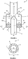
- Figure 4 shows a partial sectional view of the fluid combustion device 3 shown in Figure 3 .
- the inlet conduit 5 is generally cylindrical with a diameter D 1 and has a free first end 51.
- the outlet conduit 6 is generally cylindrical and has a diameter D 2 , which may be smaller than, equal to or larger than the diameter D 1 of the inlet conduit 5.
- the diameter D 2 of the outlet conduit 6 is larger than the diameter D 1 of the inlet conduit 5.
- the free first end 51 of the inlet conduit 5 includes an inwardly flaring frusto-conical taper 52, defining a baffle plate 53.
- an optional extension 54 projects from the taper 52.
- the taper 52 defines an opening 55 in the inlet conduit 5 which has a smaller diameter D 4 than the diameter D 1 of the inlet conduit 5, in this embodiment, though may be equal thereto in other embodiments.
- the diameter D 4 of the opening 55 of the inlet conduit 5 is smaller than the diameter D 2 of the outlet conduit 6.
- the air intake housing 7 is generally cylindrical and has a diameter D 3 , which is larger than the diameter D 1 of the inlet conduit 5 (see Figure 5 ).
- the air intake housing 7 has an end wall 71 which is fluidly sealed to the second end 62 of the outlet conduit 6 and a second, open end 72 which is open to the surrounding atmosphere.
- the end wall 71 is frusto-conical in this embodiment.
- Disposed within the air intake housing and adjacent the end wall 71 of the air intake housing 7 is a mixing chamber 73.
- the free first end 51 of the inlet conduit 5 is located inside the air intake housing 7, such that a circumferential and continuous air inlet 74a defining an air inlet passageway 74 is formed between the external surface of the inlet conduit 5 and the internal surface of the air intake housing 7.
- a protection means 8A which is a flame arrester element 8 is disposed within the air inlet passageway 74 such that it spans the entire circumference of the inlet conduit 5.
- the ignition means 41 (as shown in Figure 3 ) may be located adjacent and downstream of the mixing chamber.
- the ignition means 41 may be located at a distance equal to or greater than 2D 2 , for example equal to or greater than 5D 2 , say equal to or greater than 10D 2 from the second end 62 of the outlet conduit 6.
- the ignition means 41 may be located at a distance less than 10D 2 , for example than 5D 2 , say less than 2D 2 from the second end 62 of the outlet conduit 6. It will be appreciated that this distance between the ignition means 41 and the second end 62 of the outlet conduit 6 defines a mixing chamber 6b within the outlet conduit 6.
- the flame arrester element 8 is substantially annular in plan (as may be seen with reference to Figure 5 ) and may be fabricated by any means known in the art, for example a knitted metal mesh, a perforated plate, a coiled crimped ribbon or a sintered metal mesh structure.
- the flame arrester element 8 is configured to seat around the inlet conduit 5 and within the air intake housing 7, thereby spanning the air inlet passageway 74 therebetween.
- the flame arrester element 8 is preferably located adjacent the open end 72 of the air intake housing 7. Most preferably the flame arrester element 8 is constructed from a coiled crimped ribbon.
- the flame arrester element 8 may comprise more than one crimped ribbon element. Where more than one crimped ribbon element is provided each crimped ribbon element may be similar or may be different.
- the flame arrester element 8 should not cause a substantial impediment to flow of air A flowing into the air intake housing 7 from outside thence.
- a substantial flow impediment may reduce the mass flow rate of flow of air A flowing into the air intake housing 7 and thence entraining into the flow of fuel F. Therefore, the radial width of the air inlet passageway 74 between the external surface of the inlet conduit 5 and the internal surface of the air intake housing 7 (and hence the radial width of the flame arrester element 8) is selected in order to compensate for any restriction to the flow of air A caused by the presence of the flame arrester element 8.
- the radial width of the air inlet passageway 74 may be selected by altering the diameter D 1 of the inlet conduit 5 and/or the diameter D 3 of the air intake housing 7.
- the diameter D 4 of the opening 55 in the inlet conduit 5 may be altered in concert with any alteration to the diameter D 1 of the inlet conduit 5 and/or the diameter D 3 of the air intake housing.
- a flow of fuel F flows along the inlet conduit 5 towards the free first end 51 thereof and is emitted therefrom.
- the fuel flows along a primary flow path.
- the local flow velocity is increased whilst the local pressure of the flow is decreased, according to the Venturi effect.
- the flow of fuel F is then emitted from the opening 55 in the taper 52 with air A within the air intake housing 7 subsequently entrained into the flow due to the known principle of jetting.
- the air A is partially mixed with the fuel F within the mixing chamber 73 prior to flowing out of the air intake housing 7 and into the outlet conduit 6.
- the partially mixed air A and fuel F is then further mixed, preferably fully mixed, during passage along the mixing chamber 6b of the outlet conduit 6, due to turbulent flow of the mixture.
- a pressure differential is created between the air intake housing 7 and the ambient surroundings such that further air A is drawn into the air intake housing 7, through the flame arrester element 8 and the air inlet passageway 74.
- the air flows through the air inlet passageway 74 along a secondary flow path.
- the flow of air A along the secondary flow path is then entrained into the flow of fuel F, as described above.
- a flame arrester element 8 constructed of a coiled crimped ribbon comprises generally regular channels therethrough which may provide a guide to the flow of air A.
- these generally regular channels may direct a flow of air A into a desirable direction.
- the flow of air A may be introduced into the air intake housing 7 with improved uniformity of direction and/or with altered direction.
- the secondary flow path may be effected and/or improved by the presence of a flame arrester element 8 including generally regular channels.
- entrainment of air A into the flow of fuel F symmetrically or substantially symmetrically thereabout and/or the provision of mixing chambers 73, 6b ensures that air A and fuel F mix more fully and rapidly than in prior art systems.
- this mixture of air A and fuel F ignites and burns more efficiently and rapidly such that the generated flame front is therefore more reliable and/or robust, consequently having a reduced likelihood of extinguishment prior to reaching the open first end 61 of the outlet conduit 6.
- a fluid combustion device 3 according to the invention having a circumferential air inlet passageway 74, which is upstream of the ignition means 41, provides more efficient mixing of air A and fuel F prior to ignition thereof.
- Providing means for the ingress of a flow of air A concentrically around the majority or entirety of the circumference of the flow of fuel F maximises the surface area of the flow of fuel F against which air A is entrained, thereby maximising entrainment.
- air A is entrained into the flow of fuel F both more efficiently and more rapidly than were the flow of air A provided around a minor portion of the circumference of the flow of fuel F.
- the mixture of air A and fuel F may therefore be adjusted to a required concentration of fuel F, for example a concentration of fuel F which is easily ignitable.
- a generated flame front burning from a stoichiometric mixture of air A and fuel F burns without wasting fuel F, resulting in reduced expenditure, and without an excess of air A, hence producing a more robust and/or reliable flame front.
- the fluid combustion device 3 becomes partially blocked the fuel/air mixture may diverge from an ideal and/or stoichiometric mixture.
- the concentration of air A to fuel F within the mixture may be adjusted and therefore may be returned or maintained at or near to an ideal and/or stoichiometric mixture.
- a flame front generated by the ignition means 41 may travel back (reversed flow) along the outlet conduit 6 towards the air intake housing 7 (known as flashback). Such an event may result in a flame front and possibly a detonation propagating back along the outlet conduit 6 until they enter the air intake housing 7.
- the thus formed flame front and/or detonation may exhaust from the air intake housing 7 directly into the surrounds thereof, which may present a considerable danger to the integrity of the structure and to any personnel thereabout.
- the fluid combustion device 3 of the invention includes a flame arrester element 8 in the air inlet passageway 74 between the inlet conduit 5 and the air intake housing 7. Because the air intake housing 7 generally has a greater cross-sectional area than the outlet conduit 6, the detonation, if generated, will expand as it enters the air intake housing 7 and as a result the detonation will be, at least partially, attenuated and hence more easily contained.
- the baffle plate 53 of the inlet conduit 5 will act to divert a first portion of a flame front and/or detonation towards the flame arrester element 8.
- the opening 55 in the inlet conduit 5 has a smaller diameter D 4 than the diameter D 2 of the outlet conduit 6.
- a second portion of the flame front and/or detonation will enter the inlet conduit 5 and propagate therealong.
- the second portion is advantageously reduced in size.
- a flame front entering the opening 55 in the inlet conduit 5 cannot be sustained because the fuel F air A mixture is too rich with fuel F to combust.
- the flame arrester element 8 which will act to remove further energy from the flame front, thereby attenuating and ultimately quenching the flame front according to a known process.
- the protection means 8A may additionally or alternatively comprise
- Providing a concentrically disposed or substantially concentrically disposed air intake housing 7 and flame arrester element 8 further protects the fluid combustion device 3, flare stack 2 and any surrounding structures or personnel from flashback.
- an air intake housing 7 which is relatively wider than the outlet conduit 6 an explosion (deflagration and/or detonation) travelling back along the fluid combustion device 3 will expand upon entering the air intake housing 7.
- this expansion will result in a consequential reduction in the pressure of the explosion, resulting in, at least partial, attenuation thereof.
- the expanded explosion will then collide with the flame arrester element 8, being attenuated or contained thereby.
- the expansion of the explosion in the air intake housing 7 reduces the pressure of the explosion which subsequently collides with the flame arrester element 8, thereby protecting it from a collision with a relatively higher pressure explosion which may otherwise cause damage to the flame arrester element 8. Furthermore, the explosion is split into a first portion which collides with the flame arrester element 8 within the air intake housing 7 and a second portion which enters the inlet conduit 5. By splitting the explosion into two portions in this way the intensity thereof which collides with the flame arrester element 8 within the air intake housing 7 is reduced and consequently more readily attenuated or contained.
- the flame arrester element 8 also serves a secondary purpose as a protective barrier to prevent ingress of potentially harmful matter, for example elements capable of causing ignition, such as sparks, into the air intake housing 7 from the ambient surroundings.
- the flame arrester element 8 may be retained with the air intake housing 7 relatively thereabove.
- the flame arrester element 8 is protected from gravity feeding of unwanted particulate and fluid matter, e.g. dust and rain.
- the flame arrester element 8 is therefore less likely to become blocked and/or damaged and/or corroded and will consequently require reduced maintenance and may have an increased useful life, both of which result in reduced expenditure.
- the flame arrester element 8 may be visible from below for visible inspection by maintenance personnel, thereby reducing the difficulty (and hence expense) of periodic inspections.
- the symmetrical configuration of the fluid combustion device 3 in plan results in an even and balanced distribution of weight, e.g. relative to a primary axis along the inlet conduit 5 and/or the outlet conduit 6.
- this distribution of weight provides a more stable fluid combustion device 3 able to be supported safely, e.g. relative to the flare stack 2 and/or flare pilot 30.
- a flame arrester element 8 and air intake housing 7 within an integrated design the fluid combustion device 3 is simple and consequently has a reduced expense of manufacture relative to separate systems. Even further, the flame arrester element 8 may be accessed and even repaired or replaced during operation of the flare stack 2 and/or flare pilot 30.
- FIG. 6 to 9 there are shown alternative embodiments of the fluid combustion device showing different configurations of the free first end 51 of the inlet conduit 5 and/or in which the air intake housing 7 cooperates in differing ways with the free first end 51 of the inlet conduit 5 and/or with the second end 62 of the outlet conduit 6.
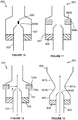
- Figure 6 shows a partial sectional view of a further fluid combustion device 103 according to the invention in which features that are similar to those of the first embodiment are identified by a preceding '10'.
- the air intake housing 107 is integrally formed with (or replaced by) the outlet conduit 106, with the flame arrester element 108 disposed therewithin and external to the inlet conduit 105.
- the free first end 1051 of the inlet conduit 105 does not include a taper or an extension (integers 52 and 54 in the embodiment shown in Figure 4 ).
- This embodiment of the fluid combustion device 103 is simpler than the embodiment shown in Figure 4 and may, as a consequence, be less expensive to manufacture.
- Figure 7 shows a partial sectional view of a further fluid combustion device 203 according to the invention in which features that are similar to those of earlier embodiments are identified by a preceding '20'.
- the free first end 2051 of the inlet conduit 205 does not include an extension (in contrast to the embodiment shown in Figure 4 ).
- the end wall 2071 of the air intake housing 207 is configured to direct the flow of air A along a secondary flow path having a first portion extending generally parallel to the primary flow path and a second portion directed towards the primary flow path of the flow of fuel F at an angle ⁇ .
- the configuration of the embodiment shown in Figure 7 results in a secondary flow path of air having a more constant and defined flow pattern.
- Figure 8 shows a partial sectional view of a further fluid combustion device 303 in which features that are similar to those of earlier embodiments are identified by a preceding '30'.
- the diameter D 1 of the inlet conduit 305 is less than the diameter D 2 of the outlet conduit 306.
- the air intake housing 307 of this fluid combustion device 303 includes concentric or substantially concentric outer and inner walls configured to remain equidistant from one another and to thereby provide an air inlet passageway 3074 therebetween.
- the inner wall of the air intake housing 307 includes a tapered first end 3073 connected to the free first end 3051 of the inlet conduit 305.
- the end wall 3071 of the air intake housing 307 is similarly tapered, such that a portion of the secondary flow path of air A is generated between the tapered first end 3073 and the end wall 3071.
- the diameter D 1 of the inlet conduit 305 may be equal to or greater than the diameter D 2 of the outlet conduit 306, where a nozzle (not shown) is provided on the free first end 3051 of the inlet conduit 305 and where the nozzle has an outlet diameter less than (or significantly less than) the diameter D 2 of the outlet conduit 306.
- the fluid combustion device 303 of Figure 8 differs from the embodiment of the fluid combustion device 203 shown in Figure 7 in that the inlet conduit 305 does not include a taper at its free first end 3051 and therefore does not have an opening of reduced diameter relative to the diameter D 1 of the inlet conduit 305. Consequently, the flow of fuel F along the inlet conduit 305 is not restricted in the embodiment of the fluid combustion device 303 shown in Figure 8 such that greater flow rates may be possible with this embodiment than with the embodiment shown in Figure 7 .
- FIG. 9 shows a partial sectional view of a further fluid combustion device 403 in which features that are similar to those of earlier embodiments are identified by a preceding '40'.
- the flame arrester element 408 and air intake housing 407 are arranged such that a portion of the second open end 4072 of the air intake housing 407 projects beyond the flame arrester element 408.
- This portion of the second open end 4072 of the air intake housing 407 may be angled with respect to the remainder of the air intake housing 407 and/or with respect to a primary flow path of fuel F through the inlet conduit 405.
- This portion of the second open end 4072 of the air intake housing 407 may comprise a frusto-conical portion thereof.
- provision of such a portion of the second open end 4072 of the air intake housing 407 reduces air flow losses adjacent this region and consequently enhances the flow of air A into the air intake housing 407 and thence entrainment of said air A into the flow of fuel F.
- FIG 10 shows a partial sectional view of a further fluid combustion device 503 in which features that are similar to those of earlier embodiments are identified by a preceding '50'.
- a baffle member 509 is provided adjacent the opening 5055 in the inlet conduit 505.
- the baffle member 509 is preferably formed from metal, such as steel, though in alternative embodiments it may be formed from any other suitable material.
- the baffle member 509 is attached to the air intake housing 507 and/or the inlet conduit 505 via attachment arms (not shown). Although the baffle member 509 is shown as being downstream of the opening 5055 this need not be the case and the baffle member 509 may instead be upstream of the opening 5055 or may instead be located at least partly in the opening 5055.
- the baffle member 509 is shown as being oval in cross-section in Figure 10 but it may have any suitable shape, for example circular, rectangular, square, triangular, irregularly shaped, etc.
- the baffle member 509 may be hollow or solid or may comprise a porous structure.
- the baffle member 509 alters the flow patterns of the flow of fuel F from the inlet conduit 505 consequently resulting in enhanced entrainment and/or mixing of air A into the flow of fuel F.
- a flow of fuel F thereagainst may be diverted according to the Coanda effect.
- a flow of fuel F diverted in this way may advantageously entrain an increased volume of air A relative to a non-diverted flow of fuel F.
- the shape and/or size and/or location of the baffle member 509 may be selected according to the dimensions and/or arrangement of the surrounding components and/or according to the operating flow rate and/or pressure of the flow of fuel F.
- Figure 11 shows a partial sectional view of a further fluid combustion device 603 in which features that are similar to those of earlier embodiments are identified by a preceding '60'.
- a further flame arrester element 608b is located in the air intake housing 607 downstream of flame arrester element 608.
- the further flame arrester element 608b entirely extends around the perimeter of the air intake housing 607.
- the further flame arrester element 608b is a plate pack flame arrester element, while the flame arrester element 608 is a crimped ribbon flame arrester element.
- the further flame arrester element 608b may comprise any suitable number of plates of suitable thickness and spacing from one another.
- the plates of the further flame arrester element 608b may be oriented in any suitable direction relative to the other components of the fluid combustion device 603.
- the wall of the air intake housing 607 includes an air inlet 608c adjacent the further flame arrester element 608b.
- the spaces between the plates of the plate pack flame arrester element of the further flame arrester element 608b provide fluid communication between the exterior and interior of the air intake housing 607, through the air inlet 608c.
- air A may flow through the air inlet 608c, through the further flame arrester element 608b and thence be entrained into a flow of fuel F in the fluid combustion device 603.
- the flame arrester element 608 may not be provided and only the further flame arrester element 608b may be provided.
- the further flame arrester element 608b may instead be a crimped ribbon flame arrester element or may be a plate pack flame arrester element or may be a perforated plate flame arrester element or may be any other suitable type of flame arrester element.
- both a flame arrester element 608 and a further flame arrester element 608b are provided both may be crimped ribbon flame arrester elements or both may be plate pack flame arrester elements or both may be perforated plate flame arrester elements.
- the flame arrester element 608 and the further flame arrester element 608b may be of different types.
- Figure 12 shows a partial sectional view of a further fluid combustion device 703 in which features that are similar to those of earlier embodiments are identified by a preceding '70'.
- a further flame arrester element 708b is located within air inlet 708c in the wall of the air intake housing 707.
- the further flame arrester element 708b is a plate pack flame arrester element. Channels between the plates of the further flame arrester element provide fluid communication between the inside of the air intake housing 707 and the surroundings thereof.
- the further flame arrester element 708b may have a first portion internal and a second portion external to the air intake housing 707. Alternatively, the further flame arrester element 708b may be entirely internal or entirely external to the air intake housing 707.
- the plates of the plate pack flame arrester element of the further flame arrester element 708b are substantially planar and are parallel to (and spaced from) one another. Planes defined by the major surfaces of one, some or all of the plates of the plate pack flame arrester element of the further flame arrester element 708b are substantially perpendicular to a primary flow path of a flow of fuel F, in use, through the inlet conduit 705. The further flame arrester element 708b entirely extends around the perimeter of the air intake housing 707.
- a flow of air A is entrained into a flow of fuel F through the further flame arrester element 708b and through the flame arrester element 708.
- the further flame arrester element 708b is configured to direct the flow of air A along a flow path which is substantially perpendicular to the primary flow path of the flow of fuel F.
- planes defined by the major surfaces of the plates of the plate pack of the further flame arrester element 708b may not be substantially perpendicular to a primary flow path of a flow of fuel F, in use, through the inlet conduit 705.
- the plates of the plate pack may be oriented at any suitable angle and may, for example define a frusto-conical shape directed either upstream or downstream of a flow of fuel F, in use.
- the flame arrester element 708 and/or the further flame arrester element 708b may be any suitable type of flame arrester element, for example may comprise a crimped ribbon flame arrester element, a plate pack flame arrester element, perforated plate flame arrester element, etc. Additionally or alternatively, the flame arrester element 708 and the further flame arrester element 708b may be the same type of flame arrester element or may be different types of flame arrester element. Additionally or alternatively, the flame arrester element 708 may not be provided. Where the flame arrester element 708 is not provided the flow of air A, in use, may flow only through the further flame arrester element 708b.
- FIG 13 shows a partial section view of a further fluid combustion device 803 in which features that are similar to those of earlier embodiments are identified by a preceding '80'.
- the air intake housing 807 includes a throttle 807a located downstream of the inlet conduit and upstream of the outlet conduit 806.
- the throttle 807a is defined by a converging portion 807b of the air intake housing 807, which converges or narrows in a downstream direction, and a diverging portion 807c of the air intake housing 807, which diverges or expands in a downstream direction.
- the throttle 807a is located downstream of the opening 8055 of the inlet conduit 805.
- the throttle 807a may be located adjacent the opening 8055 of the inlet conduit 805 or, alternatively, upstream thereof. In use, the throttle 807a is configured to throttle a flow of fuel F therethrough and hence to increase the local velocity whilst reducing the local pressure thereof.
- a further embodiment of the invention provides a fluid combustion device, e.g. for use with or in a gas flare or flare stack, the fluid combustion device comprising a flow conduit with a fuel inlet, an outlet, a primary flow axis or path through the flow conduit and a continuous air inlet or plural air inlets between the fuel inlet and the outlet, wherein the or each air inlet comprises a protection means mounted in or on or otherwise associated therewith, and wherein the one or more air inlets is or are disposed symmetrically or substantially symmetrically about the primary flow axis or path such that air is entrained, in use, into a flow of fuel passing along the flow conduit for ignition (or and ignited) in or at the outlet to produce a flame, e.g. a continuous flame or flame front.
- the flame arrester element has been shown as comprising only a plate pack or crimped ribbon structure, alternatively the flame arrester element may include a solid portion which may also be included at its core ( e.g . its centre) or at one of its edges.
- the flame arrester elements have been shown as toroidal they need not be and may instead be any suitable shape, for example frusto-conical and/or flared or inclined inwardly or outwardly with respect to the primary flow path along the inlet conduit.
- the flame arrester element (and the further flame arrester element, where provided) is described as being either a crimped ribbon flame arrester element or a plate pack flame arrester element this need not be the case and instead the flame arrester element (and/or the further flame arrester element, where provided) may be any suitable type of flame arrester element, for example comprising one or more perforated plates.
- the air inlet (as shown in any of the above described embodiments) is described as being continuous this need not be the case and instead the air inlet may be interrupted at one or more location, e.g. circumferentially, in order to provide plural air inlets. Where more than one air inlet is provided each may be provided with a flame arrester element.
- the flame arrester element (and/or the further flame arrester element if provided) may be continuous or may comprise plural flame arrester sub-elements, for example which may be separated from one another by any suitable means.
- inlet conduit, outlet conduit and housing are shown as cylindrical they need not be and any or all of them may instead have a square or hexagonal cross-section or any other suitable shape.
- edges and/or corners and/or junctions may be rounded or curved, e.g. smoothly curved.
- the junction between the side wall of the air intake housing 7 and the end wall 71 thereof may be rounded or curved, e.g. smoothly curved.
- the air inlet may comprise a compressed air supply, for example may be connected to a source of compressed air.
- the connection may extend in a direction parallel to the inlet conduit.
- the protection means or flame arrester element may thereby protect the source of compressed air, for example one or more pump, from explosion damage.
Landscapes
- Engineering & Computer Science (AREA)
- Mechanical Engineering (AREA)
- General Engineering & Computer Science (AREA)
- Environmental & Geological Engineering (AREA)
- Chemical & Material Sciences (AREA)
- Combustion & Propulsion (AREA)
- Gas Burners (AREA)
Claims (15)
- Fluidverbrennungsvorrichtung (3) zur Verwendung mit einem Fackelpilot (30), wobei die Fluidverbrennungsvorrichtung (3) eine Strömungsröhre mit einem Brennstoffeinlass (5), einem Auslass (6), einem primären Strömungspfad durch die Strömungsröhre und einen kontinuierlichen Lufteinlass (74) oder mehrere Lufteinlässe (74; 608C; 708C) zwischen dem Brennstoffeinlass (5) und dem Auslass (6) umfasst, wobei der oder jeder Lufteinlass (74; 608C; 708C) ein Schutzmittel (8A, 608b, 708b) umfasst, da darin oder daran angebracht oder anderweitig zugeordnet ist, wobei im Einsatz Luft in einer Brennstoffströmung mitgeführt wird, die entlang der Strömungsröhre verläuft, um in, an oder stromabwärts des Auslasses (6) zu zünden, um eine Flammenfront zu erzeugen, dadurch gekennzeichnet, dass der oder jeder Lufteinlass (74; 608c; 708c) einen ringförmigen Lufteinlass umfasst, der den primären Strömungspfad umgibt.
- Fluidverbrennungsvorrichtung (3) nach Anspruch 1, wobei der oder jeder Lufteinlass (74; 608c; 708c) einen ringförmigen Lufteinlass umfasst, der mit dem primären Strömungspfad konzentrisch ist.
- Fluidverbrennungsvorrichtung (3) nach Anspruch 1 oder 2, wobei das Schutzmittel (8A, 608b, 708b) ringförmig ist und in dem oder jedem Lufteinlass (74; 608c; 708c) aufgenommen wird oder damit ausgerichtet ist.
- Fluidverbrennungsvorrichtung (3) nach Anspruch 1, 2 oder 3, wobei das Schutzmittel (8A, 608b, 708b) ein oder mehrere Crimpbandelemente und/oder ein oder mehrere perforierte Platten und/oder eine oder mehrere Plattenpackungen und/oder ringförmige Plattenstapel umfasst.
- Fluidverbrennungsvorrichtung (3) nach einem der vorstehenden Ansprüche, wobei das Schutzmittel (8A, 608b, 708b) eine Explosionsentlastungsvorrichtung umfasst.
- Fluidverbrennungsvorrichtung (3) nach einem der vorstehenden Ansprüche, wobei der Strömungsquerschnitt der Strömungsröhre an, angrenzend an oder stromaufwärts des Lufteinlasses oder der Lufteinlässe (74; 608c; 708c) zunimmt, um unterstützend dabei zu wirken, dass Luft im Einsatz in einer Brennstoffströmung mitgeführt wird, die durch die Strömungsröhre verläuft.
- Fluidverbrennungsvorrichtung (3) nach einem der vorstehenden Ansprüche, wobei die Strömungsröhre eine Strömungsbegrenzung (55) an, angrenzend an oder stromaufwärts des Lufteinlasses oder der Lufteinlässe (74; 608c; 708c) umfasst, um unterstützend dabei zu wirken, dass Luft im Einsatz in einer Brennstoffströmung mitgeführt wird, die durch die Strömungsröhre verläuft.
- Fluidverbrennungsvorrichtung (3) nach einem der vorstehenden Ansprüche, wobei die Strömungsröhre einen ersten Teil stromaufwärts des Lufteinlasses oder der Lufteinlässe (74; 608c; 708c) umfasst und einen zweiten Teil stromabwärts des Lufteinlasses oder der Lufteinlässe (74; 608c; 708c), wobei der erste Teil einen Brennstoffauslass (55) in Fluidkommunikation mit einem Einlass (62) und kleiner als dieser Einlass des zweiten Teils aufweist, wobei der erste Teil der Strömungsröhre vorzugsweise eine Verjüngung von einem ersten Strömungsquerschnitt zu dem Brennstoffauslass (55) aufweist, der einen zweiten Strömungsquerschnitt aufweist, der kleiner ist als der erste Strömungsquerschnitt, wodurch die oder eine Strömungsbegrenzung bereitgestellt wird, um unterstützend dabei zu wirken, dass Luft im Einsatz in einer Brennstoffströmung mitgeführt wird, die durch die Strömungsröhre verläuft, und/oder wobei der zweite Teil den Auslass (6) der Fluidverbrennungsvorrichtung umfassen kann.
- Fluidverbrennungsvorrichtung (3) nach einem der vorstehenden Ansprüche, wobei der oder jeder Lufteinlass (74; 608c; 708c) einen Lufteinlasskanal mit einem sekundären Strömungspfad umfasst, der sich wenigstens teilweise in einem spitzen Winkel im Verhältnis zu dem primären Strömungspfad erstreckt, wobei vorzugsweise wenigstens ein Teil des Lufteinlasskanals verjüngt oder konisch ist.
- Fluidverbrennungsvorrichtung (3) nach Anspruch 9, wobei der Lufteinlasskanal zwei oder mehr Teile umfasst, die jeweils einen entsprechenden Strömungspfad aufweisen, wobei sich ein erster Teil des Lufteinlasskanals entlang einer ersten Richtung parallel zu dem primären Strömungspfad erstreckt, und wobei sich ein zweiter Teil dessen entlang einer zweiten Richtung in einem spitzen Winkel im Verhältnis zu dem primären Strömungspfad und in die Strömungsröhre erstreckt, wobei der zweite Teil des Lufteinlasskanals verjüngt oder konisch sein kann.
- Fluidverbrennungsvorrichtung (3) nach einem der Ansprüche 1 bis 8, wobei der oder jeder Lufteinlass (74; 608c; 708c) einen Lufteinlasskanal mit einem sekundären Strömungspfad umfasst, der sich wenigstens teilweise senkrecht zu dem primären Strömungspfad erstreckt.
- Fluidverbrennungsvorrichtung (3) nach einem der vorstehenden Ansprüche, wobei die Fluidverbrennungsvorrichtung (3) ferner ein oder mehrere Umlenkelemente (53) umfasst, die so gestaltet sind, dass sie die Strömungsrichtung des Brennstoffs und/oder von Luft dort vorbei ändern.
- Fluidverbrennungsvorrichtung (3) nach einem der vorstehenden Ansprüche, wobei das Schutzmittel (8A, 608b, 708b) ein Flammenabsperrelement (8) umfasst.
- Fackelpilot (30) oder Fackel (2), der bzw. die eine Fluidverbrennungsvorrichtung (3) nach einem der vorstehenden Ansprüche umfasst.
- Verfahren zur Erzeugung einer Flammenfront zum Zünden eines Fackelpiloten (30), wobei das Verfahren folgendes umfasst: Leiten einer Brennstoffströmung durch eine Strömungsröhre entlang eines primären Strömungspfads, wobei Luft über einen kontinuierlichen Lufteinlass oder mehrere ringförmige Lufteinlässe (74; 608c; 708c) in dem durch der Strömungsröhre verlaufenden Brennstoffströmung mitgeführt wird, um das Gemisch aus Brennstoff und Luft in, an oder stromabwärts des Auslasses (6) zu zünden, um eine Flammenfront zu erzeugen, wobei der oder jeder Lufteinlass (74; 608c; 708c) ein Schutzmittel (8A, 608b, 708b) oder ein Flammenabsperrelement (8) umfasst, das darin oder daran angebracht oder damit anderweitig zugeordnet ist, und dadurch gekennzeichnet, dass der Lufteinlass bzw. die Lufteinlässe (74; 608c, 708c) die primäre Strömungsachse oder den Pfad und/oder die Strömungsröhre umgeben und/oder damit konzentrisch sind.
Applications Claiming Priority (2)
| Application Number | Priority Date | Filing Date | Title |
|---|---|---|---|
| GB201606969 | 2016-04-21 | ||
| PCT/GB2017/051118 WO2017182824A1 (en) | 2016-04-21 | 2017-04-21 | Fluid combustion device |
Publications (2)
| Publication Number | Publication Date |
|---|---|
| EP3446037A1 EP3446037A1 (de) | 2019-02-27 |
| EP3446037B1 true EP3446037B1 (de) | 2020-03-18 |
Family
ID=58638888
Family Applications (1)
| Application Number | Title | Priority Date | Filing Date |
|---|---|---|---|
| EP17719892.6A Active EP3446037B1 (de) | 2016-04-21 | 2017-04-21 | Flüssigkeitsverbrennungsvorrichtung |
Country Status (3)
| Country | Link |
|---|---|
| EP (1) | EP3446037B1 (de) |
| GB (1) | GB2551255B (de) |
| WO (1) | WO2017182824A1 (de) |
Families Citing this family (2)
| Publication number | Priority date | Publication date | Assignee | Title |
|---|---|---|---|---|
| CN109297042B (zh) * | 2018-06-26 | 2023-12-22 | 宜兴市智博环境设备有限公司 | 一种喷射装置及废气输送管路阻火系统 |
| CN117419348B (zh) * | 2023-12-18 | 2024-03-05 | 西安紫光环保科技有限公司 | 一种煤气放散点火火炬 |
Family Cites Families (2)
| Publication number | Priority date | Publication date | Assignee | Title |
|---|---|---|---|---|
| US4025281A (en) * | 1975-08-08 | 1977-05-24 | Westech Industrial Ltd. | Method and apparatus for flaring combustible waste gases |
| US4248585A (en) * | 1978-12-04 | 1981-02-03 | Gulf Oil Corporation | Flare ignition apparatus |
-
2017
- 2017-04-21 GB GB1706372.8A patent/GB2551255B/en active Active
- 2017-04-21 EP EP17719892.6A patent/EP3446037B1/de active Active
- 2017-04-21 WO PCT/GB2017/051118 patent/WO2017182824A1/en not_active Ceased
Non-Patent Citations (1)
| Title |
|---|
| None * |
Also Published As
| Publication number | Publication date |
|---|---|
| GB201706372D0 (en) | 2017-06-07 |
| EP3446037A1 (de) | 2019-02-27 |
| WO2017182824A1 (en) | 2017-10-26 |
| GB2551255B (en) | 2019-05-29 |
| GB2551255A (en) | 2017-12-13 |
Similar Documents
| Publication | Publication Date | Title |
|---|---|---|
| JP7299424B2 (ja) | さか火現象を防止することができる水素ガス燃焼装置 | |
| US11724138B2 (en) | Flame arresters | |
| CN102901098B (zh) | 地面火炬多头高效预混型燃烧系统 | |
| US3649211A (en) | Air augmented duct burner | |
| KR20100122458A (ko) | 공기 플레어 장치 및 그 방법 | |
| CN202884924U (zh) | 地面火炬预混型燃烧器 | |
| CA2854383C (en) | Combustor for discrete low and high pressure vapor combustion | |
| KR20030017357A (ko) | 안정적 플레어 파이로트와 그 방법 | |
| JPH09178113A (ja) | 火炉の火炎・圧力脈動抑制方法および火炉 | |
| EP1486729B1 (de) | Verbrennungsofen | |
| US10119443B2 (en) | Spark arrestor and methods associated therewith | |
| EP0210314A1 (de) | Verfahren und Apparat zum Verbrennen von Brennstoff | |
| WO2017182824A1 (en) | Fluid combustion device | |
| US3887324A (en) | Method for non-polluting combustion of waste gases | |
| US4087235A (en) | Apparatus for incinerating waste gases | |
| RU2170389C2 (ru) | Факельная установка для сжигания сбросных газов | |
| CN104764013B (zh) | 具有增强联焰能力的引射式燃烧装置 | |
| EP1770249B1 (de) | Abgasdiffusor | |
| US4604047A (en) | Flare for and method of flaring high velocity gas | |
| JP5537299B2 (ja) | 廃棄物処理設備の燃焼室 | |
| JP5537298B2 (ja) | 廃棄物処理設備の燃焼室の燃焼バーナ | |
| JP2014122743A (ja) | 粉体燃焼装置及び粉体燃焼装置の運転方法 | |
| CN209310004U (zh) | 自冷式模块化燃烧装置 | |
| JPS63271007A (ja) | 微粉炭燃焼装置 | |
| CN105546536A (zh) | 引射式燃烧装置及其燃料控制系统 |
Legal Events
| Date | Code | Title | Description |
|---|---|---|---|
| STAA | Information on the status of an ep patent application or granted ep patent |
Free format text: STATUS: UNKNOWN |
|
| STAA | Information on the status of an ep patent application or granted ep patent |
Free format text: STATUS: THE INTERNATIONAL PUBLICATION HAS BEEN MADE |
|
| PUAI | Public reference made under article 153(3) epc to a published international application that has entered the european phase |
Free format text: ORIGINAL CODE: 0009012 |
|
| STAA | Information on the status of an ep patent application or granted ep patent |
Free format text: STATUS: REQUEST FOR EXAMINATION WAS MADE |
|
| 17P | Request for examination filed |
Effective date: 20181024 |
|
| AK | Designated contracting states |
Kind code of ref document: A1 Designated state(s): AL AT BE BG CH CY CZ DE DK EE ES FI FR GB GR HR HU IE IS IT LI LT LU LV MC MK MT NL NO PL PT RO RS SE SI SK SM TR |
|
| AX | Request for extension of the european patent |
Extension state: BA ME |
|
| DAV | Request for validation of the european patent (deleted) | ||
| DAX | Request for extension of the european patent (deleted) | ||
| GRAP | Despatch of communication of intention to grant a patent |
Free format text: ORIGINAL CODE: EPIDOSNIGR1 |
|
| STAA | Information on the status of an ep patent application or granted ep patent |
Free format text: STATUS: GRANT OF PATENT IS INTENDED |
|
| INTG | Intention to grant announced |
Effective date: 20191009 |
|
| GRAS | Grant fee paid |
Free format text: ORIGINAL CODE: EPIDOSNIGR3 |
|
| GRAA | (expected) grant |
Free format text: ORIGINAL CODE: 0009210 |
|
| STAA | Information on the status of an ep patent application or granted ep patent |
Free format text: STATUS: THE PATENT HAS BEEN GRANTED |
|
| AK | Designated contracting states |
Kind code of ref document: B1 Designated state(s): AL AT BE BG CH CY CZ DE DK EE ES FI FR GR HR HU IE IS IT LI LT LU LV MC MK MT NL NO PL PT RO RS SE SI SK SM TR |
|
| RBV | Designated contracting states (corrected) |
Designated state(s): AL AT BE BG CH CY CZ DE DK EE ES FI FR GR HR HU IE IS IT LI LT LU LV MC MK MT NL NO PL PT RO RS SE SI SK SM TR |
|
| REG | Reference to a national code |
Ref country code: DE Ref legal event code: R096 Ref document number: 602017013291 Country of ref document: DE |
|
| REG | Reference to a national code |
Ref country code: AT Ref legal event code: REF Ref document number: 1246319 Country of ref document: AT Kind code of ref document: T Effective date: 20200415 Ref country code: IE Ref legal event code: FG4D |
|
| REG | Reference to a national code |
Ref country code: NO Ref legal event code: T2 Effective date: 20200318 |
|
| REG | Reference to a national code |
Ref country code: NL Ref legal event code: FP |
|
| PG25 | Lapsed in a contracting state [announced via postgrant information from national office to epo] |
Ref country code: RS Free format text: LAPSE BECAUSE OF FAILURE TO SUBMIT A TRANSLATION OF THE DESCRIPTION OR TO PAY THE FEE WITHIN THE PRESCRIBED TIME-LIMIT Effective date: 20200318 Ref country code: FI Free format text: LAPSE BECAUSE OF FAILURE TO SUBMIT A TRANSLATION OF THE DESCRIPTION OR TO PAY THE FEE WITHIN THE PRESCRIBED TIME-LIMIT Effective date: 20200318 |
|
| PG25 | Lapsed in a contracting state [announced via postgrant information from national office to epo] |
Ref country code: HR Free format text: LAPSE BECAUSE OF FAILURE TO SUBMIT A TRANSLATION OF THE DESCRIPTION OR TO PAY THE FEE WITHIN THE PRESCRIBED TIME-LIMIT Effective date: 20200318 Ref country code: LV Free format text: LAPSE BECAUSE OF FAILURE TO SUBMIT A TRANSLATION OF THE DESCRIPTION OR TO PAY THE FEE WITHIN THE PRESCRIBED TIME-LIMIT Effective date: 20200318 Ref country code: SE Free format text: LAPSE BECAUSE OF FAILURE TO SUBMIT A TRANSLATION OF THE DESCRIPTION OR TO PAY THE FEE WITHIN THE PRESCRIBED TIME-LIMIT Effective date: 20200318 Ref country code: BG Free format text: LAPSE BECAUSE OF FAILURE TO SUBMIT A TRANSLATION OF THE DESCRIPTION OR TO PAY THE FEE WITHIN THE PRESCRIBED TIME-LIMIT Effective date: 20200618 Ref country code: GR Free format text: LAPSE BECAUSE OF FAILURE TO SUBMIT A TRANSLATION OF THE DESCRIPTION OR TO PAY THE FEE WITHIN THE PRESCRIBED TIME-LIMIT Effective date: 20200619 |
|
| REG | Reference to a national code |
Ref country code: LT Ref legal event code: MG4D |
|
| PG25 | Lapsed in a contracting state [announced via postgrant information from national office to epo] |
Ref country code: RO Free format text: LAPSE BECAUSE OF FAILURE TO SUBMIT A TRANSLATION OF THE DESCRIPTION OR TO PAY THE FEE WITHIN THE PRESCRIBED TIME-LIMIT Effective date: 20200318 Ref country code: SK Free format text: LAPSE BECAUSE OF FAILURE TO SUBMIT A TRANSLATION OF THE DESCRIPTION OR TO PAY THE FEE WITHIN THE PRESCRIBED TIME-LIMIT Effective date: 20200318 Ref country code: IS Free format text: LAPSE BECAUSE OF FAILURE TO SUBMIT A TRANSLATION OF THE DESCRIPTION OR TO PAY THE FEE WITHIN THE PRESCRIBED TIME-LIMIT Effective date: 20200718 Ref country code: CZ Free format text: LAPSE BECAUSE OF FAILURE TO SUBMIT A TRANSLATION OF THE DESCRIPTION OR TO PAY THE FEE WITHIN THE PRESCRIBED TIME-LIMIT Effective date: 20200318 Ref country code: LT Free format text: LAPSE BECAUSE OF FAILURE TO SUBMIT A TRANSLATION OF THE DESCRIPTION OR TO PAY THE FEE WITHIN THE PRESCRIBED TIME-LIMIT Effective date: 20200318 Ref country code: PT Free format text: LAPSE BECAUSE OF FAILURE TO SUBMIT A TRANSLATION OF THE DESCRIPTION OR TO PAY THE FEE WITHIN THE PRESCRIBED TIME-LIMIT Effective date: 20200812 Ref country code: SM Free format text: LAPSE BECAUSE OF FAILURE TO SUBMIT A TRANSLATION OF THE DESCRIPTION OR TO PAY THE FEE WITHIN THE PRESCRIBED TIME-LIMIT Effective date: 20200318 Ref country code: EE Free format text: LAPSE BECAUSE OF FAILURE TO SUBMIT A TRANSLATION OF THE DESCRIPTION OR TO PAY THE FEE WITHIN THE PRESCRIBED TIME-LIMIT Effective date: 20200318 |
|
| REG | Reference to a national code |
Ref country code: AT Ref legal event code: MK05 Ref document number: 1246319 Country of ref document: AT Kind code of ref document: T Effective date: 20200318 |
|
| REG | Reference to a national code |
Ref country code: CH Ref legal event code: PL |
|
| REG | Reference to a national code |
Ref country code: DE Ref legal event code: R097 Ref document number: 602017013291 Country of ref document: DE |
|
| PG25 | Lapsed in a contracting state [announced via postgrant information from national office to epo] |
Ref country code: MC Free format text: LAPSE BECAUSE OF FAILURE TO SUBMIT A TRANSLATION OF THE DESCRIPTION OR TO PAY THE FEE WITHIN THE PRESCRIBED TIME-LIMIT Effective date: 20200318 |
|
| PLBE | No opposition filed within time limit |
Free format text: ORIGINAL CODE: 0009261 |
|
| STAA | Information on the status of an ep patent application or granted ep patent |
Free format text: STATUS: NO OPPOSITION FILED WITHIN TIME LIMIT |
|
| PG25 | Lapsed in a contracting state [announced via postgrant information from national office to epo] |
Ref country code: ES Free format text: LAPSE BECAUSE OF FAILURE TO SUBMIT A TRANSLATION OF THE DESCRIPTION OR TO PAY THE FEE WITHIN THE PRESCRIBED TIME-LIMIT Effective date: 20200318 Ref country code: LI Free format text: LAPSE BECAUSE OF NON-PAYMENT OF DUE FEES Effective date: 20200430 Ref country code: LU Free format text: LAPSE BECAUSE OF NON-PAYMENT OF DUE FEES Effective date: 20200421 Ref country code: CH Free format text: LAPSE BECAUSE OF NON-PAYMENT OF DUE FEES Effective date: 20200430 Ref country code: DK Free format text: LAPSE BECAUSE OF FAILURE TO SUBMIT A TRANSLATION OF THE DESCRIPTION OR TO PAY THE FEE WITHIN THE PRESCRIBED TIME-LIMIT Effective date: 20200318 Ref country code: AT Free format text: LAPSE BECAUSE OF FAILURE TO SUBMIT A TRANSLATION OF THE DESCRIPTION OR TO PAY THE FEE WITHIN THE PRESCRIBED TIME-LIMIT Effective date: 20200318 |
|
| REG | Reference to a national code |
Ref country code: BE Ref legal event code: MM Effective date: 20200430 |
|
| 26N | No opposition filed |
Effective date: 20201221 |
|
| PG25 | Lapsed in a contracting state [announced via postgrant information from national office to epo] |
Ref country code: BE Free format text: LAPSE BECAUSE OF NON-PAYMENT OF DUE FEES Effective date: 20200430 Ref country code: PL Free format text: LAPSE BECAUSE OF FAILURE TO SUBMIT A TRANSLATION OF THE DESCRIPTION OR TO PAY THE FEE WITHIN THE PRESCRIBED TIME-LIMIT Effective date: 20200318 |
|
| PG25 | Lapsed in a contracting state [announced via postgrant information from national office to epo] |
Ref country code: IE Free format text: LAPSE BECAUSE OF NON-PAYMENT OF DUE FEES Effective date: 20200421 |
|
| PG25 | Lapsed in a contracting state [announced via postgrant information from national office to epo] |
Ref country code: SI Free format text: LAPSE BECAUSE OF FAILURE TO SUBMIT A TRANSLATION OF THE DESCRIPTION OR TO PAY THE FEE WITHIN THE PRESCRIBED TIME-LIMIT Effective date: 20200318 |
|
| PG25 | Lapsed in a contracting state [announced via postgrant information from national office to epo] |
Ref country code: TR Free format text: LAPSE BECAUSE OF FAILURE TO SUBMIT A TRANSLATION OF THE DESCRIPTION OR TO PAY THE FEE WITHIN THE PRESCRIBED TIME-LIMIT Effective date: 20200318 Ref country code: MT Free format text: LAPSE BECAUSE OF FAILURE TO SUBMIT A TRANSLATION OF THE DESCRIPTION OR TO PAY THE FEE WITHIN THE PRESCRIBED TIME-LIMIT Effective date: 20200318 Ref country code: CY Free format text: LAPSE BECAUSE OF FAILURE TO SUBMIT A TRANSLATION OF THE DESCRIPTION OR TO PAY THE FEE WITHIN THE PRESCRIBED TIME-LIMIT Effective date: 20200318 |
|
| PG25 | Lapsed in a contracting state [announced via postgrant information from national office to epo] |
Ref country code: MK Free format text: LAPSE BECAUSE OF FAILURE TO SUBMIT A TRANSLATION OF THE DESCRIPTION OR TO PAY THE FEE WITHIN THE PRESCRIBED TIME-LIMIT Effective date: 20200318 Ref country code: AL Free format text: LAPSE BECAUSE OF FAILURE TO SUBMIT A TRANSLATION OF THE DESCRIPTION OR TO PAY THE FEE WITHIN THE PRESCRIBED TIME-LIMIT Effective date: 20200318 |
|
| REG | Reference to a national code |
Ref country code: DE Ref legal event code: R081 Ref document number: 602017013291 Country of ref document: DE Owner name: THE PROTECTOSEAL COMPANY, BENSENVILLE, US Free format text: FORMER OWNER: ELMAC TECHNOLOGIES LIMITED, HOLYWELL, FLINTSHIRE, GB |
|
| REG | Reference to a national code |
Ref country code: NL Ref legal event code: PD Owner name: THE PROTECTOSEAL COMPANY; US Free format text: DETAILS ASSIGNMENT: CHANGE OF OWNER(S), ASSIGNMENT; FORMER OWNER NAME: ELMAC TECHNOLOGIES LIMITED Effective date: 20250522 |
|
| PGFP | Annual fee paid to national office [announced via postgrant information from national office to epo] |
Ref country code: NL Payment date: 20260415 Year of fee payment: 10 |
|
| PGFP | Annual fee paid to national office [announced via postgrant information from national office to epo] |
Ref country code: IT Payment date: 20260413 Year of fee payment: 10 |
|
| PGFP | Annual fee paid to national office [announced via postgrant information from national office to epo] |
Ref country code: DE Payment date: 20260417 Year of fee payment: 10 |
|
| PGFP | Annual fee paid to national office [announced via postgrant information from national office to epo] |
Ref country code: NO Payment date: 20260417 Year of fee payment: 10 |
|
| PGFP | Annual fee paid to national office [announced via postgrant information from national office to epo] |
Ref country code: FR Payment date: 20260423 Year of fee payment: 10 |