EP3446059B1 - Laminierte mikrokanal-wärmetauscher - Google Patents
Laminierte mikrokanal-wärmetauscher Download PDFInfo
- Publication number
- EP3446059B1 EP3446059B1 EP17786489.9A EP17786489A EP3446059B1 EP 3446059 B1 EP3446059 B1 EP 3446059B1 EP 17786489 A EP17786489 A EP 17786489A EP 3446059 B1 EP3446059 B1 EP 3446059B1
- Authority
- EP
- European Patent Office
- Prior art keywords
- sheets
- lanes
- microchannels
- thermally conductive
- heat exchanger
- Prior art date
- Legal status (The legal status is an assumption and is not a legal conclusion. Google has not performed a legal analysis and makes no representation as to the accuracy of the status listed.)
- Active
Links
Images




Classifications
-
- F—MECHANICAL ENGINEERING; LIGHTING; HEATING; WEAPONS; BLASTING
- F28—HEAT EXCHANGE IN GENERAL
- F28D—HEAT-EXCHANGE APPARATUS, NOT PROVIDED FOR IN ANOTHER SUBCLASS, IN WHICH THE HEAT-EXCHANGE MEDIA DO NOT COME INTO DIRECT CONTACT
- F28D15/00—Heat-exchange apparatus with the intermediate heat-transfer medium in closed tubes passing into or through the conduit walls ; Heat-exchange apparatus employing intermediate heat-transfer medium or bodies
- F28D15/02—Heat-exchange apparatus with the intermediate heat-transfer medium in closed tubes passing into or through the conduit walls ; Heat-exchange apparatus employing intermediate heat-transfer medium or bodies in which the medium condenses and evaporates, e.g. heat pipes
- F28D15/0233—Heat-exchange apparatus with the intermediate heat-transfer medium in closed tubes passing into or through the conduit walls ; Heat-exchange apparatus employing intermediate heat-transfer medium or bodies in which the medium condenses and evaporates, e.g. heat pipes the conduits having a particular shape, e.g. non-circular cross-section, annular
-
- F—MECHANICAL ENGINEERING; LIGHTING; HEATING; WEAPONS; BLASTING
- F28—HEAT EXCHANGE IN GENERAL
- F28F—DETAILS OF HEAT-EXCHANGE AND HEAT-TRANSFER APPARATUS, OF GENERAL APPLICATION
- F28F13/00—Arrangements for modifying heat-transfer, e.g. increasing, decreasing
- F28F13/06—Arrangements for modifying heat-transfer, e.g. increasing, decreasing by affecting the pattern of flow of the heat-exchange media
-
- F—MECHANICAL ENGINEERING; LIGHTING; HEATING; WEAPONS; BLASTING
- F28—HEAT EXCHANGE IN GENERAL
- F28F—DETAILS OF HEAT-EXCHANGE AND HEAT-TRANSFER APPARATUS, OF GENERAL APPLICATION
- F28F3/00—Plate-like or laminated elements; Assemblies of plate-like or laminated elements
- F28F3/08—Elements constructed for building-up into stacks, e.g. capable of being taken apart for cleaning
- F28F3/086—Elements constructed for building-up into stacks, e.g. capable of being taken apart for cleaning having one or more openings therein forming tubular heat-exchange passages
-
- F—MECHANICAL ENGINEERING; LIGHTING; HEATING; WEAPONS; BLASTING
- F28—HEAT EXCHANGE IN GENERAL
- F28F—DETAILS OF HEAT-EXCHANGE AND HEAT-TRANSFER APPARATUS, OF GENERAL APPLICATION
- F28F7/00—Elements not covered by group F28F1/00, F28F3/00 or F28F5/00
- F28F7/02—Blocks traversed by passages for heat-exchange media
-
- F—MECHANICAL ENGINEERING; LIGHTING; HEATING; WEAPONS; BLASTING
- F28—HEAT EXCHANGE IN GENERAL
- F28D—HEAT-EXCHANGE APPARATUS, NOT PROVIDED FOR IN ANOTHER SUBCLASS, IN WHICH THE HEAT-EXCHANGE MEDIA DO NOT COME INTO DIRECT CONTACT
- F28D21/00—Heat-exchange apparatus not covered by any of the groups F28D1/00 - F28D20/00
- F28D2021/0019—Other heat exchangers for particular applications; Heat exchange systems not otherwise provided for
- F28D2021/0028—Other heat exchangers for particular applications; Heat exchange systems not otherwise provided for for cooling heat generating elements, e.g. for cooling electronic components or electric devices
-
- F—MECHANICAL ENGINEERING; LIGHTING; HEATING; WEAPONS; BLASTING
- F28—HEAT EXCHANGE IN GENERAL
- F28F—DETAILS OF HEAT-EXCHANGE AND HEAT-TRANSFER APPARATUS, OF GENERAL APPLICATION
- F28F2260/00—Heat exchangers or heat exchange elements having special size, e.g. microstructures
- F28F2260/02—Heat exchangers or heat exchange elements having special size, e.g. microstructures having microchannels
-
- F—MECHANICAL ENGINEERING; LIGHTING; HEATING; WEAPONS; BLASTING
- F28—HEAT EXCHANGE IN GENERAL
- F28F—DETAILS OF HEAT-EXCHANGE AND HEAT-TRANSFER APPARATUS, OF GENERAL APPLICATION
- F28F2265/00—Safety or protection arrangements; Arrangements for preventing malfunction
- F28F2265/24—Safety or protection arrangements; Arrangements for preventing malfunction for electrical insulation
Definitions
- This invention relates to microchannel-based heat exchangers, including microchannel-based evaporators used to cool heat sources with high heat fluxes such as electronic devices.
- the fluid heat exchangers dissipate heat by thermally conducting the heat into internal passages of the exchanger, through which a coolant fluid flows, absorbing the heat conducted across the walls of the exchanger, and then transporting the fluid outside the exchanger, where the heat is rejected to an external heat sink.
- the coolant fluid flowing through the exchanger may be a gas, it is generally preferable to use a liquid, as liquids have higher heat capacities and heat transfer coefficients than gases.
- the liquid may remain in a single phase, or the liquid may partially or completely evaporate within the internal passages of the exchanger.
- US9310135 discloses a heat exchanger provided by assembling a plurality of individual plates having opposed faces, wherein flow channels are machined through those opposed faces, and the plates are interconnected with intervening shim plates. End plates are connected to an assembly of such plates and intermediate plates, to form a preform, which is then machined to a desired cross section.
- the resulting structure has a plurality of passages therethrough in one direction, and a second plurality of passages therethrough in a second direction, the passages fluidly isolated from one another.
- the resulting structure is configurable to a specific geometry of a flow passage, and enables heat exchange between fluids passing through the different flow channels
- the thermally conductive sheets can further define access channel openings at each end of the lanes, which when stacked create access channels for the microchannels.
- the sheets can define a more dense packing of cross ribs in at least one inlet end of the heat exchanger to reduce the open cross-section at the inlet end of the lanes.
- the aspect ratio of the microchannels can be above 4: 1.
- the aspect ratio of the microchannels can be above 8: 1.
- the apparatus can further include thermally conductive separator sheets located between groups of the thermally conductive sheets to form a multilayer heat exchanger.
- the sheets can be made of at least one conductive metal.
- the sheets can be made of sinterable thermally conductive ceramics. The sheets can be bonded or fused.
- the microchannels can have a hydraulic diameter of below 500 microns.
- the microchannels can have a hydraulic diameter of below 200 microns.
- the base can be a base plate that is thicker than each of the sheets and the cover can include access channels in communication with the microchannels.
- the base can be thermally conductive yet electrically insulating.
- the heat exchanger can be constructed for boiling or evaporating fluid service, with the heat exchanger further including flow restrictors at the inlet ends of the microchannels.
- the flow restrictors can be formed by alternately closing an end of the first slot in a lane of slots with cross-ribs that are wider than the bulk of the cross-ribs between slots, with the alternating closed-ended lanes of slots being staggered with respect to the lanes of slots above or below, in alternating layers of slotted sheets, such that, when the sheets are stacked and bonded together, the cross-section of the parallel channels that are formed have a checkerboard pattern across the inlets of the plurality of channels, which serve as integral flow restrictors covering substantially 50% of a cross-sectional area of the main channels.
- Systems according to the invention can help to suppress Ledinegg effects and thereby allow heat exchangers to work with two-phase systems.
- microchannel evaporators according to the invention can avoid flow instabilities, due to the Ledinegg effect, whereby boiling within multiple (parallel) microchannels might otherwise be non-uniform and due to the interaction of varying pressure drop as boiling develops in the various channels, resulting in periodic backflow into the inlet header or manifold. This can help to achieve stabilized and substantially uniform boiling flows and thereby result in improved and more stable thermal performance when cooling high-flux heat sources.
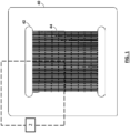
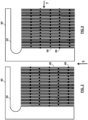
- the sheet of the first type 40 includes a plurality of lines 44 of multiple slots 46, with the slots in a given line being separated by thin wall that functions as a cross-rib 48. These lines span between the common cut-out areas connected to the slots at either end of each line of slots. The common cut-out areas align with each other to form input and output manifolds when sheets are stacked.
- alternating two or more types of sheets allows the microchannels to be defined in three-dimensions.
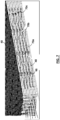
- the laminated core structure is assembled by alternating slotted-and-ribbed sheets having the cross-ribs staggered with respect to each other when the sheets are stacked so that each line of slots forms a continuous but serpentine flow path (see also Figs. 5-7 ).
- thermally conductive un-slotted separator sheets 60 having cut-out areas 62 that align with the common cut-out areas of the slotted-and-ribbed sheets can also be used on the top and bottom of the core and/or to separate layers of microchannels.
- stacking sets of the alternating slotted-and-ribbed-sheets, flanked by un-slotted separator sheets allows the formation of a core structure that includes one or more layers each having a plurality of microchannels with interspersed cross-ribs that intermittently partially interrupt the flow path with providing lateral strengthening of the channel walls.
- the number of alternating slotted-and-ribbed-sheets in each layer, along with the sheet thickness and slot width, determines the channel depth : width aspect ratio of the channel layers.
- the layered stacked sheets are preferably bonded to ensure that all the sheets are in thermally conductive communication with each other.
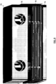
- the resulting sub-assembly can then be bonded to a base plate 74 to ensure that the base plate is in thermally conductive communication with the microchannel layers, and a cover 78 can be placed and sealed on top of the resulting assembly of microchannel layers 76 bonded to the base plate, thereby forming a complete microchannel heat exchanger assembly 70.
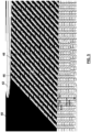
- the input sides of the microchannels preferably include flow restrictors where the exchanger is used in boiling or evaporative service. These restrictors can be built into the laminate structure by providing extra cross-ribs 82 at the inputs of the microchannels.
- the laminated structures described above enable microchannel heat exchangers having one or more layers of microchannels with hydraulic diameters of less than 500 microns, with the microchannels having arbitrarily high depth : width aspect ratios and with thin walls.
- the channels have internal cross-ribs connecting the channel's walls, and provide mechanical strength to the channel walls and way of breaking up the fluid stream lines to improve heat transfer.
- the thermally conductive sheet and base plate materials are preferably, but not limited to, metals and their alloys; non-metallic elements, thermally conductive carbon allotropes, or thermally conductive ceramics. Bonding of the sheets can be by any convenient means that ensure high thermal conduction between the sheets and the base plate.
- microchannels are formed by inserting, between stacks of slotted-and-ribbed sheets, additional thermally conductive un-slotted separator sheets having cut-out areas that align with the common cut-out areas of the slotted-and-ribbed sheets.
- the microchannels of any layer may have the same or different depth: width aspect ratio and hydraulic diameter compared to the microchannels in the other layers.
- the depth: width aspect ratio of the resulting microchannels can be at least 2:1, and preferably between 4:1 and 15: 1.
- the walls between the resulting microchannels can be less than 200 microns and preferably between 40 and 100 microns thick.
- the base plate and microchannel walls can be fabricated from materials having thermal conductivities in excess of 100 W/m-K.
- the hydraulic diameter of the resulting microchannels can be less than 500 microns, and preferably between 50 and 200 microns.
- the liquid inlet channels can be provided with flow restrictors, to prevent backflow or two-phase flow instabilities. These inlet restrictions are provided by closing-off the inlet-side ends of the slots (e.g. by adding additional cross-ribs) of alternate sheets in the stacks of slotted-and-ribbed sheets, thereby reducing the open cross-sectional area of the inlets to the channels relative to the main channel cross-section beyond the closed portions.
- the length of the closed-off (restriction) portions of the microchannels is at least 1 mm.
- microchannel heat exchanger e.g. microchannel stacks, base plate, and over plate
- the various components of the microchannel heat exchanger can be bonded or fused, so that the exchanger is hermetically sealed (with the exception of the fluid inlet and outlet ports that communicate with the manifolds), so that the exchanger can hold elevated internal pressures. Bonding or fusing may be accomplished by any convenient means.
- microchannel heat exchanger e.g. microchannel stacks, base plate, and over plate
- the various components of the microchannel heat exchanger can also be held together by mechanical means, with suitable seals between components, so that the exchanger can hold elevated internal pressures.
- the bottom base of the layer of the microchannel exchanger is made from or is coated with a thermally conductive yet electrically insulating ceramic or dielectric solid, such as aluminum nitride, silicon carbide, beryllium oxide, diamond film, and the like.
- the microchannel exchanger then serves as the substrate for (heat generating) electronic components, which are mounted on, and in thermal contact with, the electrically insulating but thermally conductive underside surface of the exchanger.
- microchannel heat exchanger e.g. the thermally conductive base, the microchannel layers, manifolds, covers, fluid inlet and outlet ports, the slotted-and-ribbed sheets, etc.
- thermally conductive base e.g. the thermally conductive base
- microchannel layers e.g. the thermally conductive base
- manifolds e.g. the thermally conductive base
- covers e.g. the thermally conductive base
- fluid inlet and outlet ports e.g. the thermally conductive base
- slotted-and-ribbed sheets, etc. may be fabricated by any convenient means consistent with the final assembly of the heat exchangers. Such means may include, but are not limited to, the following methods and combinations thereof:
- Embodiments according to the invention can be developed for a variety of different cooling configurations and applied to a variety of different cooling tasks. For example, they can implemented in connection with the teachings of published PCT application no. WO2009/085307, filed December 26, 2008 and published US application no. US-2009-0229794, filed on November 10, 2008 .
Landscapes
- Engineering & Computer Science (AREA)
- Physics & Mathematics (AREA)
- Thermal Sciences (AREA)
- Mechanical Engineering (AREA)
- General Engineering & Computer Science (AREA)
- Life Sciences & Earth Sciences (AREA)
- Sustainable Development (AREA)
- Cooling Or The Like Of Semiconductors Or Solid State Devices (AREA)
- Cooling Or The Like Of Electrical Apparatus (AREA)
- Heat-Exchange Devices With Radiators And Conduit Assemblies (AREA)
- Physical Or Chemical Processes And Apparatus (AREA)
Claims (15)
- Mikrokanal-Wärmetauscher (70), umfassend:eine Abdeckung (78) mit einem ersten Zugangskanal und einem zweiten Zugangskanal,eine wärmeleitende Basis (74),eine Vielzahl von wärmeleitenden Platten (40) zwischen der Abdeckung (78) und der Basis (74), die jeweils eine Reihe nebeneinanderliegender, in einer Strömungsrichtung ausgerichteter Bahnen (44) definieren, wobei die Bahnen (44) jeweils eine Vielzahl ausgerichteter Schlitze (46) einschließen, die Mikrokanalsegmente definieren, die sich entlang der Strömungsrichtung erstrecken und durch Querrippen (48) getrennt sind, die sich über die Bahnen (44) erstrecken,wobei die Platten (40) weiter gemeinsame Ausschnittbereiche (42) in Verbindung mit den Bahnen (44) an beiden Enden der Bahnen (44) definieren,wobei die Platten (40) in einer Richtung senkrecht zur Strömungsrichtung zwischen der Basis (74) und der Abdeckung (78) gestapelt sind, so dass zumindest einige der Rippen (48) in benachbarten Platten (40) entlang der Strömungsrichtung gegeneinander versetzt sind und es dadurch den Mikrokanalsegmenten in derselben Bahn (44) in benachbarten Platten (40) ermöglicht wird, entlang der Strömungsrichtung miteinander zu kommunizieren, um eine Vielzahl von benachbarten Mikrokanälen mit mehreren Platten im Wärmetauscher (70) zu definieren, die sich jeweils zwischen den Ausschnittbereichen (42) entlang der Strömungsrichtung erstrecken, undwobei die Platten (40) zwischen der Basis (74) und der Abdeckung (78) gestapelt sind, so dass die gemeinsamen Ausschnittbereiche (42) mindestens einen Eingangsverteiler und mindestens einen Ausgangsverteiler bilden, die jeweils mit dem ersten Zugangskanal und dem zweiten Zugangskanal auf der Abdeckung (78) ausgerichtet sind.
- Vorrichtung nach Anspruch 1 wobei die wärmeleitenden Platten (40) weiter Zugangskanalöffnungen an jedem Ende der Bahnen (44) definieren, die, wenn sie gestapelt sind, Zugangskanäle für die Mikrokanäle schaffen.
- Vorrichtung nach Anspruch 1 wobei die Platten (40) eine dichtere Packung von Querrippen (48) in mindestens einem Einlassende des Wärmetauschers (70) definieren, um den offenen Querschnitt am Einlassende der Bahnen (44) relativ zu einem Querschnitt eines Abschnitts der Bahnen (44) zwischen den Einlass- und Auslassenden der Bahnen (44) zu verringern.
- Vorrichtung nach Anspruch 1 wobei das Seitenverhältnis der Mikrokanäle über 4:1 liegt.
- Vorrichtung nach Anspruch 1 wobei das Seitenverhältnis der Mikrokanäle über 8:1 liegt.
- Vorrichtung nach Anspruch 1, die weiter wärmeleitende Trennplatten (60) einschließt, die sich zwischen Gruppen der wärmeleitenden Platten (40) befinden, um einen mehrschichtigen Wärmetauscher (70) zu bilden.
- Vorrichtung nach Anspruch 1 wobei die Platten (40) aus mindestens einem wärmeleitenden Metall hergestellt sind.
- Vorrichtung nach Anspruch 1 wobei die Platten (40) aus sinterbarer wärmeleitender Keramik hergestellt sind.
- Vorrichtung nach Anspruch 1 wobei die Platten (40) verklebt oder verschmolzen sind.
- Vorrichtung nach Anspruch 1 wobei die Mikrokanäle einen hydraulischen Durchmesser von unter 500 Mikrometern aufweisen.
- Vorrichtung nach Anspruch 1 wobei die Mikrokanäle einen Hydraulikdurchmesser von unter 200 Mikrometern aufweisen.
- Vorrichtung nach Anspruch 1 wobei die Basis eine Basisplatte (74) ist, die dicker ist als jede der Platten (40).
- Vorrichtung nach Anspruch 1 wobei die Basis (74) wärmeleitend, jedoch elektrisch isolierend ist.
- Vorrichtung nach Anspruch 1, wobei der Wärmetauscher (70) für einen Einsatz mit siedendem oder verdampfendem Fluid ausgelegt ist, und wobei der Wärmetauscher (70) weiter Durchflussbegrenzer an den Einlassenden der Mikrokanäle einschließt.
- Vorrichtung nach Anspruch 14 wobei die Durchflussbegrenzer dadurch gebildet sind, dass ein Eingangsende jeder zweiten Bahn (44) in jeder der Platten (40) mit einer Querrippe (48) verschlossen wird, wobei die Bahnen (44) von Schlitzen (46) mit verschlossenen Enden in Bezug aufeinander in benachbarten Platten (40) versetzt sind, wenn die Platten (40) gestapelt und miteinander verklebt sind, um ein Schachbrettmuster über den Einlässen der Vielzahl von Kanälen zu bilden.
Applications Claiming Priority (3)
| Application Number | Priority Date | Filing Date | Title |
|---|---|---|---|
| US201662324327P | 2016-04-18 | 2016-04-18 | |
| US201715402511A | 2017-01-10 | 2017-01-10 | |
| PCT/US2017/028183 WO2017184635A1 (en) | 2016-04-18 | 2017-04-18 | Laminated microchannel heat exchangers |
Publications (3)
| Publication Number | Publication Date |
|---|---|
| EP3446059A1 EP3446059A1 (de) | 2019-02-27 |
| EP3446059A4 EP3446059A4 (de) | 2020-01-01 |
| EP3446059B1 true EP3446059B1 (de) | 2024-06-26 |
Family
ID=60116305
Family Applications (1)
| Application Number | Title | Priority Date | Filing Date |
|---|---|---|---|
| EP17786489.9A Active EP3446059B1 (de) | 2016-04-18 | 2017-04-18 | Laminierte mikrokanal-wärmetauscher |
Country Status (7)
| Country | Link |
|---|---|
| EP (1) | EP3446059B1 (de) |
| KR (1) | KR102494649B1 (de) |
| CN (1) | CN109416224B (de) |
| DK (1) | DK3446059T3 (de) |
| FI (1) | FI3446059T3 (de) |
| IL (1) | IL263805A (de) |
| WO (1) | WO2017184635A1 (de) |
Families Citing this family (5)
| Publication number | Priority date | Publication date | Assignee | Title |
|---|---|---|---|---|
| US11732978B2 (en) | 2016-04-18 | 2023-08-22 | Qcip Holdings, Llc | Laminated microchannel heat exchangers |
| CN113446883B (zh) * | 2021-06-25 | 2022-10-25 | 西安交通大学 | 一种基于弹性湍流的双流体回路错排波型微通道散热器 |
| TWI827117B (zh) * | 2022-06-29 | 2023-12-21 | 國立勤益科技大學 | 3d列印微流體熱沉應用在彈性電子設備的散熱裝置 |
| US20240186218A1 (en) * | 2022-10-21 | 2024-06-06 | Semiconductor Components Industries, Llc | Molded power modules with fluidic-channel cooled substrates |
| CN118089458B (zh) * | 2024-03-27 | 2024-08-23 | 中国石油大学(华东) | 一种微通道柔性针肋作用下的流动沸腾强化换热装置 |
Family Cites Families (16)
| Publication number | Priority date | Publication date | Assignee | Title |
|---|---|---|---|---|
| FR2701554B1 (fr) * | 1993-02-12 | 1995-05-12 | Transcal | Echangeur de chaleur pour composants électroniques et appareillages électro-techniques. |
| CN1057424C (zh) * | 1996-02-29 | 2000-10-11 | 中国科学院上海光学精密机械研究所 | 微通道冷却热沉 |
| FR2763204A1 (fr) * | 1997-05-12 | 1998-11-13 | Ferraz | Echangeur de chaleur pour composants electroniques et appareillages electrotechniques |
| US6446442B1 (en) * | 1999-10-07 | 2002-09-10 | Hydrocool Pty Limited | Heat exchanger for an electronic heat pump |
| US20050189342A1 (en) * | 2004-02-23 | 2005-09-01 | Samer Kabbani | Miniature fluid-cooled heat sink with integral heater |
| KR100594185B1 (ko) * | 2004-12-02 | 2006-06-28 | 주식회사 이노윌 | 3차원 마이크로 채널을 구비한 플레이트 및 이를 이용한열교환기 |
| JP2007127398A (ja) * | 2005-10-05 | 2007-05-24 | Seiko Epson Corp | 熱交換器、熱交換器の製造方法、液冷システム、光源装置、プロジェクタ、電子デバイスユニット、電子機器 |
| CN1946278A (zh) * | 2005-10-05 | 2007-04-11 | 精工爱普生株式会社 | 热交换器、其制造方法、液冷系统、光源装置、投影机、电子器件单元及电子设备 |
| CN100584169C (zh) * | 2006-04-21 | 2010-01-20 | 富准精密工业(深圳)有限公司 | 液冷散热装置 |
| US8418751B2 (en) * | 2008-05-13 | 2013-04-16 | International Business Machines Corporation | Stacked and redundant chip coolers |
| US9310135B1 (en) | 2010-05-28 | 2016-04-12 | Cool Energy, Inc. | Configureable heat exchanger |
| CN201830605U (zh) * | 2010-10-12 | 2011-05-11 | 讯凯国际股份有限公司 | 液冷散热装置及其热交换器 |
| CN102003899B (zh) * | 2010-12-01 | 2012-05-02 | 杭州沈氏换热器有限公司 | 一种微通道换热器 |
| CN201897410U (zh) * | 2010-12-01 | 2011-07-13 | 杭州沈氏换热器有限公司 | 一种微通道换热器 |
| JP5944104B2 (ja) * | 2011-03-15 | 2016-07-05 | 株式会社東芝 | 熱交換器 |
| PT2730878T (pt) * | 2012-11-07 | 2019-05-30 | Alfa Laval Corp Ab | Bloco de placas e método de fazer um bloco de placas |
-
2017
- 2017-04-18 KR KR1020187033234A patent/KR102494649B1/ko active Active
- 2017-04-18 WO PCT/US2017/028183 patent/WO2017184635A1/en not_active Ceased
- 2017-04-18 FI FIEP17786489.9T patent/FI3446059T3/fi active
- 2017-04-18 DK DK17786489.9T patent/DK3446059T3/da active
- 2017-04-18 CN CN201780037866.1A patent/CN109416224B/zh active Active
- 2017-04-18 EP EP17786489.9A patent/EP3446059B1/de active Active
-
2018
- 2018-12-18 IL IL263805A patent/IL263805A/en unknown
Also Published As
| Publication number | Publication date |
|---|---|
| EP3446059A1 (de) | 2019-02-27 |
| FI3446059T3 (fi) | 2024-09-25 |
| DK3446059T3 (da) | 2024-09-30 |
| CN109416224B (zh) | 2022-05-06 |
| KR20190016489A (ko) | 2019-02-18 |
| KR102494649B1 (ko) | 2023-01-31 |
| CN109416224A (zh) | 2019-03-01 |
| EP3446059A4 (de) | 2020-01-01 |
| IL263805A (en) | 2019-03-31 |
| WO2017184635A1 (en) | 2017-10-26 |
Similar Documents
| Publication | Publication Date | Title |
|---|---|---|
| EP3446058B1 (de) | Mikrokanalverdampfer mit reduziertem druckabfall | |
| US11732978B2 (en) | Laminated microchannel heat exchangers | |
| US20220282931A1 (en) | Heat exchanger device | |
| US6935411B2 (en) | Normal-flow heat exchanger | |
| CN109416224B (zh) | 层压微通道热交换器 | |
| US7836597B2 (en) | Method of fabricating high surface to volume ratio structures and their integration in microheat exchangers for liquid cooling system | |
| US7278474B2 (en) | Heat exchanger | |
| US7302998B2 (en) | Normal-flow heat exchanger | |
| CN1629595A (zh) | 强制液热槽 | |
| US20140041836A1 (en) | Sealed self-contained fluidic cooling device | |
| TW201315960A (zh) | 疊層式散熱器 | |
| US20180045469A1 (en) | Heat exchanger device | |
| JP4721412B2 (ja) | 冷却器およびその製造方法 | |
| JP6162836B2 (ja) | 熱交換器 | |
| CN116666329B (zh) | 冷却集成的氮化镓模块及其制备方法 | |
| WO2002055942A2 (en) | Normal-flow heat exchanger | |
| CN118632482A (zh) | 一种紧凑型大功率散热器 | |
| JP2004333083A (ja) | 熱交換器 | |
| HK1076506A (en) | High heat flux single-phase heat exchanger |
Legal Events
| Date | Code | Title | Description |
|---|---|---|---|
| STAA | Information on the status of an ep patent application or granted ep patent |
Free format text: STATUS: THE INTERNATIONAL PUBLICATION HAS BEEN MADE |
|
| PUAI | Public reference made under article 153(3) epc to a published international application that has entered the european phase |
Free format text: ORIGINAL CODE: 0009012 |
|
| STAA | Information on the status of an ep patent application or granted ep patent |
Free format text: STATUS: REQUEST FOR EXAMINATION WAS MADE |
|
| 17P | Request for examination filed |
Effective date: 20181119 |
|
| AK | Designated contracting states |
Kind code of ref document: A1 Designated state(s): AL AT BE BG CH CY CZ DE DK EE ES FI FR GB GR HR HU IE IS IT LI LT LU LV MC MK MT NL NO PL PT RO RS SE SI SK SM TR |
|
| AX | Request for extension of the european patent |
Extension state: BA ME |
|
| DAV | Request for validation of the european patent (deleted) | ||
| DAX | Request for extension of the european patent (deleted) | ||
| A4 | Supplementary search report drawn up and despatched |
Effective date: 20191128 |
|
| RIC1 | Information provided on ipc code assigned before grant |
Ipc: B81B 1/00 20060101ALI20191122BHEP Ipc: F28D 9/00 20060101AFI20191122BHEP |
|
| STAA | Information on the status of an ep patent application or granted ep patent |
Free format text: STATUS: EXAMINATION IS IN PROGRESS |
|
| 17Q | First examination report despatched |
Effective date: 20221221 |
|
| GRAP | Despatch of communication of intention to grant a patent |
Free format text: ORIGINAL CODE: EPIDOSNIGR1 |
|
| STAA | Information on the status of an ep patent application or granted ep patent |
Free format text: STATUS: GRANT OF PATENT IS INTENDED |
|
| INTG | Intention to grant announced |
Effective date: 20240119 |
|
| GRAS | Grant fee paid |
Free format text: ORIGINAL CODE: EPIDOSNIGR3 |
|
| GRAA | (expected) grant |
Free format text: ORIGINAL CODE: 0009210 |
|
| STAA | Information on the status of an ep patent application or granted ep patent |
Free format text: STATUS: THE PATENT HAS BEEN GRANTED |
|
| AK | Designated contracting states |
Kind code of ref document: B1 Designated state(s): AL AT BE BG CH CY CZ DE DK EE ES FI FR GB GR HR HU IE IS IT LI LT LU LV MC MK MT NL NO PL PT RO RS SE SI SK SM TR |
|
| REG | Reference to a national code |
Ref country code: GB Ref legal event code: FG4D |
|
| REG | Reference to a national code |
Ref country code: CH Ref legal event code: EP |
|
| REG | Reference to a national code |
Ref country code: DE Ref legal event code: R096 Ref document number: 602017082831 Country of ref document: DE |
|
| REG | Reference to a national code |
Ref country code: FI Ref legal event code: FGE |
|
| REG | Reference to a national code |
Ref country code: DK Ref legal event code: T3 Effective date: 20240924 |
|
| REG | Reference to a national code |
Ref country code: NL Ref legal event code: FP |
|
| PG25 | Lapsed in a contracting state [announced via postgrant information from national office to epo] |
Ref country code: BG Free format text: LAPSE BECAUSE OF FAILURE TO SUBMIT A TRANSLATION OF THE DESCRIPTION OR TO PAY THE FEE WITHIN THE PRESCRIBED TIME-LIMIT Effective date: 20240626 |
|
| PG25 | Lapsed in a contracting state [announced via postgrant information from national office to epo] |
Ref country code: HR Free format text: LAPSE BECAUSE OF FAILURE TO SUBMIT A TRANSLATION OF THE DESCRIPTION OR TO PAY THE FEE WITHIN THE PRESCRIBED TIME-LIMIT Effective date: 20240626 |
|
| REG | Reference to a national code |
Ref country code: LT Ref legal event code: MG9D |
|
| PG25 | Lapsed in a contracting state [announced via postgrant information from national office to epo] |
Ref country code: GR Free format text: LAPSE BECAUSE OF FAILURE TO SUBMIT A TRANSLATION OF THE DESCRIPTION OR TO PAY THE FEE WITHIN THE PRESCRIBED TIME-LIMIT Effective date: 20240927 |
|
| REG | Reference to a national code |
Ref country code: NL Ref legal event code: PD Owner name: QCIP HOLDINGS, LLC; US Free format text: DETAILS ASSIGNMENT: CHANGE OF OWNER(S), ASSIGNMENT; FORMER OWNER NAME: OREGON STATE UNIVERSITY Effective date: 20241018 Ref country code: DE Ref legal event code: R081 Ref document number: 602017082831 Country of ref document: DE Owner name: QCIP HOLDINGS, LLC, STRAFFORD, US Free format text: FORMER OWNER: OREGON STATE UNIVERSITY, CORVALLIS, OR, US |
|
| PG25 | Lapsed in a contracting state [announced via postgrant information from national office to epo] |
Ref country code: LV Free format text: LAPSE BECAUSE OF FAILURE TO SUBMIT A TRANSLATION OF THE DESCRIPTION OR TO PAY THE FEE WITHIN THE PRESCRIBED TIME-LIMIT Effective date: 20240626 |
|
| PG25 | Lapsed in a contracting state [announced via postgrant information from national office to epo] |
Ref country code: NO Free format text: LAPSE BECAUSE OF FAILURE TO SUBMIT A TRANSLATION OF THE DESCRIPTION OR TO PAY THE FEE WITHIN THE PRESCRIBED TIME-LIMIT Effective date: 20240926 Ref country code: LV Free format text: LAPSE BECAUSE OF FAILURE TO SUBMIT A TRANSLATION OF THE DESCRIPTION OR TO PAY THE FEE WITHIN THE PRESCRIBED TIME-LIMIT Effective date: 20240626 Ref country code: HR Free format text: LAPSE BECAUSE OF FAILURE TO SUBMIT A TRANSLATION OF THE DESCRIPTION OR TO PAY THE FEE WITHIN THE PRESCRIBED TIME-LIMIT Effective date: 20240626 Ref country code: GR Free format text: LAPSE BECAUSE OF FAILURE TO SUBMIT A TRANSLATION OF THE DESCRIPTION OR TO PAY THE FEE WITHIN THE PRESCRIBED TIME-LIMIT Effective date: 20240927 Ref country code: BG Free format text: LAPSE BECAUSE OF FAILURE TO SUBMIT A TRANSLATION OF THE DESCRIPTION OR TO PAY THE FEE WITHIN THE PRESCRIBED TIME-LIMIT Effective date: 20240626 Ref country code: RS Free format text: LAPSE BECAUSE OF FAILURE TO SUBMIT A TRANSLATION OF THE DESCRIPTION OR TO PAY THE FEE WITHIN THE PRESCRIBED TIME-LIMIT Effective date: 20240926 |
|
| RAP2 | Party data changed (patent owner data changed or rights of a patent transferred) |
Owner name: QCIP HOLDINGS, LLC |
|
| PG25 | Lapsed in a contracting state [announced via postgrant information from national office to epo] |
Ref country code: PT Free format text: LAPSE BECAUSE OF FAILURE TO SUBMIT A TRANSLATION OF THE DESCRIPTION OR TO PAY THE FEE WITHIN THE PRESCRIBED TIME-LIMIT Effective date: 20241028 |
|
| PG25 | Lapsed in a contracting state [announced via postgrant information from national office to epo] |
Ref country code: PT Free format text: LAPSE BECAUSE OF FAILURE TO SUBMIT A TRANSLATION OF THE DESCRIPTION OR TO PAY THE FEE WITHIN THE PRESCRIBED TIME-LIMIT Effective date: 20241028 |
|
| REG | Reference to a national code |
Ref country code: AT Ref legal event code: PC Ref document number: 1698031 Country of ref document: AT Kind code of ref document: T Owner name: QCIP HOLDINGS, LLC, US Effective date: 20241210 |
|
| PG25 | Lapsed in a contracting state [announced via postgrant information from national office to epo] |
Ref country code: PL Free format text: LAPSE BECAUSE OF FAILURE TO SUBMIT A TRANSLATION OF THE DESCRIPTION OR TO PAY THE FEE WITHIN THE PRESCRIBED TIME-LIMIT Effective date: 20240626 |
|
| PG25 | Lapsed in a contracting state [announced via postgrant information from national office to epo] |
Ref country code: EE Free format text: LAPSE BECAUSE OF FAILURE TO SUBMIT A TRANSLATION OF THE DESCRIPTION OR TO PAY THE FEE WITHIN THE PRESCRIBED TIME-LIMIT Effective date: 20240626 |
|
| PG25 | Lapsed in a contracting state [announced via postgrant information from national office to epo] |
Ref country code: IS Free format text: LAPSE BECAUSE OF FAILURE TO SUBMIT A TRANSLATION OF THE DESCRIPTION OR TO PAY THE FEE WITHIN THE PRESCRIBED TIME-LIMIT Effective date: 20241026 |
|
| PG25 | Lapsed in a contracting state [announced via postgrant information from national office to epo] |
Ref country code: CZ Free format text: LAPSE BECAUSE OF FAILURE TO SUBMIT A TRANSLATION OF THE DESCRIPTION OR TO PAY THE FEE WITHIN THE PRESCRIBED TIME-LIMIT Effective date: 20240626 |
|
| PG25 | Lapsed in a contracting state [announced via postgrant information from national office to epo] |
Ref country code: RO Free format text: LAPSE BECAUSE OF FAILURE TO SUBMIT A TRANSLATION OF THE DESCRIPTION OR TO PAY THE FEE WITHIN THE PRESCRIBED TIME-LIMIT Effective date: 20240626 Ref country code: SK Free format text: LAPSE BECAUSE OF FAILURE TO SUBMIT A TRANSLATION OF THE DESCRIPTION OR TO PAY THE FEE WITHIN THE PRESCRIBED TIME-LIMIT Effective date: 20240626 |
|
| PG25 | Lapsed in a contracting state [announced via postgrant information from national office to epo] |
Ref country code: ES Free format text: LAPSE BECAUSE OF FAILURE TO SUBMIT A TRANSLATION OF THE DESCRIPTION OR TO PAY THE FEE WITHIN THE PRESCRIBED TIME-LIMIT Effective date: 20240626 Ref country code: SM Free format text: LAPSE BECAUSE OF FAILURE TO SUBMIT A TRANSLATION OF THE DESCRIPTION OR TO PAY THE FEE WITHIN THE PRESCRIBED TIME-LIMIT Effective date: 20240626 |
|
| PG25 | Lapsed in a contracting state [announced via postgrant information from national office to epo] |
Ref country code: SM Free format text: LAPSE BECAUSE OF FAILURE TO SUBMIT A TRANSLATION OF THE DESCRIPTION OR TO PAY THE FEE WITHIN THE PRESCRIBED TIME-LIMIT Effective date: 20240626 Ref country code: SK Free format text: LAPSE BECAUSE OF FAILURE TO SUBMIT A TRANSLATION OF THE DESCRIPTION OR TO PAY THE FEE WITHIN THE PRESCRIBED TIME-LIMIT Effective date: 20240626 Ref country code: RO Free format text: LAPSE BECAUSE OF FAILURE TO SUBMIT A TRANSLATION OF THE DESCRIPTION OR TO PAY THE FEE WITHIN THE PRESCRIBED TIME-LIMIT Effective date: 20240626 Ref country code: PL Free format text: LAPSE BECAUSE OF FAILURE TO SUBMIT A TRANSLATION OF THE DESCRIPTION OR TO PAY THE FEE WITHIN THE PRESCRIBED TIME-LIMIT Effective date: 20240626 Ref country code: IS Free format text: LAPSE BECAUSE OF FAILURE TO SUBMIT A TRANSLATION OF THE DESCRIPTION OR TO PAY THE FEE WITHIN THE PRESCRIBED TIME-LIMIT Effective date: 20241026 Ref country code: ES Free format text: LAPSE BECAUSE OF FAILURE TO SUBMIT A TRANSLATION OF THE DESCRIPTION OR TO PAY THE FEE WITHIN THE PRESCRIBED TIME-LIMIT Effective date: 20240626 Ref country code: EE Free format text: LAPSE BECAUSE OF FAILURE TO SUBMIT A TRANSLATION OF THE DESCRIPTION OR TO PAY THE FEE WITHIN THE PRESCRIBED TIME-LIMIT Effective date: 20240626 Ref country code: CZ Free format text: LAPSE BECAUSE OF FAILURE TO SUBMIT A TRANSLATION OF THE DESCRIPTION OR TO PAY THE FEE WITHIN THE PRESCRIBED TIME-LIMIT Effective date: 20240626 |
|
| REG | Reference to a national code |
Ref country code: GB Ref legal event code: 732E Free format text: REGISTERED BETWEEN 20250109 AND 20250115 |
|
| PG25 | Lapsed in a contracting state [announced via postgrant information from national office to epo] |
Ref country code: IT Free format text: LAPSE BECAUSE OF FAILURE TO SUBMIT A TRANSLATION OF THE DESCRIPTION OR TO PAY THE FEE WITHIN THE PRESCRIBED TIME-LIMIT Effective date: 20240626 |
|
| REG | Reference to a national code |
Ref country code: DE Ref legal event code: R097 Ref document number: 602017082831 Country of ref document: DE |
|
| PLBE | No opposition filed within time limit |
Free format text: ORIGINAL CODE: 0009261 |
|
| STAA | Information on the status of an ep patent application or granted ep patent |
Free format text: STATUS: NO OPPOSITION FILED WITHIN TIME LIMIT |
|
| 26N | No opposition filed |
Effective date: 20250327 |
|
| PG25 | Lapsed in a contracting state [announced via postgrant information from national office to epo] |
Ref country code: SE Free format text: LAPSE BECAUSE OF FAILURE TO SUBMIT A TRANSLATION OF THE DESCRIPTION OR TO PAY THE FEE WITHIN THE PRESCRIBED TIME-LIMIT Effective date: 20240626 |
|
| REG | Reference to a national code |
Ref country code: AT Ref legal event code: UEP Ref document number: 1698031 Country of ref document: AT Kind code of ref document: T Effective date: 20240626 |
|
| PG25 | Lapsed in a contracting state [announced via postgrant information from national office to epo] |
Ref country code: LU Free format text: LAPSE BECAUSE OF NON-PAYMENT OF DUE FEES Effective date: 20250418 |
|
| PG25 | Lapsed in a contracting state [announced via postgrant information from national office to epo] |
Ref country code: MC Free format text: LAPSE BECAUSE OF FAILURE TO SUBMIT A TRANSLATION OF THE DESCRIPTION OR TO PAY THE FEE WITHIN THE PRESCRIBED TIME-LIMIT Effective date: 20240626 |
|
| REG | Reference to a national code |
Ref country code: BE Ref legal event code: MM Effective date: 20250430 |
|
| PG25 | Lapsed in a contracting state [announced via postgrant information from national office to epo] |
Ref country code: BE Free format text: LAPSE BECAUSE OF NON-PAYMENT OF DUE FEES Effective date: 20250430 |
|
| REG | Reference to a national code |
Ref country code: CH Ref legal event code: U11 Free format text: ST27 STATUS EVENT CODE: U-0-0-U10-U11 (AS PROVIDED BY THE NATIONAL OFFICE) Effective date: 20260501 |
|
| PGFP | Annual fee paid to national office [announced via postgrant information from national office to epo] |
Ref country code: NL Payment date: 20260430 Year of fee payment: 10 |
|
| PG25 | Lapsed in a contracting state [announced via postgrant information from national office to epo] |
Ref country code: CY Free format text: LAPSE BECAUSE OF FAILURE TO SUBMIT A TRANSLATION OF THE DESCRIPTION OR TO PAY THE FEE WITHIN THE PRESCRIBED TIME-LIMIT Effective date: 20240626 |
|
| PG25 | Lapsed in a contracting state [announced via postgrant information from national office to epo] |
Ref country code: LT Free format text: LAPSE BECAUSE OF FAILURE TO SUBMIT A TRANSLATION OF THE DESCRIPTION OR TO PAY THE FEE WITHIN THE PRESCRIBED TIME-LIMIT Effective date: 20240626 |
|
| PGFP | Annual fee paid to national office [announced via postgrant information from national office to epo] |
Ref country code: GB Payment date: 20260421 Year of fee payment: 10 Ref country code: DK Payment date: 20260428 Year of fee payment: 10 |
|
| PGFP | Annual fee paid to national office [announced via postgrant information from national office to epo] |
Ref country code: DE Payment date: 20260427 Year of fee payment: 10 |
|
| PGFP | Annual fee paid to national office [announced via postgrant information from national office to epo] |
Ref country code: AT Payment date: 20260429 Year of fee payment: 10 Ref country code: FI Payment date: 20260429 Year of fee payment: 10 |
|
| PGFP | Annual fee paid to national office [announced via postgrant information from national office to epo] |
Ref country code: CH Payment date: 20260501 Year of fee payment: 10 Ref country code: IE Payment date: 20260429 Year of fee payment: 10 |
|
| PGFP | Annual fee paid to national office [announced via postgrant information from national office to epo] |
Ref country code: FR Payment date: 20260428 Year of fee payment: 10 |