EP3446579A1 - Unité évaporateur pour un inhalateur et procédé de commande d'une unité évaporateur - Google Patents
Unité évaporateur pour un inhalateur et procédé de commande d'une unité évaporateur Download PDFInfo
- Publication number
- EP3446579A1 EP3446579A1 EP18190453.3A EP18190453A EP3446579A1 EP 3446579 A1 EP3446579 A1 EP 3446579A1 EP 18190453 A EP18190453 A EP 18190453A EP 3446579 A1 EP3446579 A1 EP 3446579A1
- Authority
- EP
- European Patent Office
- Prior art keywords
- evaporator unit
- heating element
- electronic control
- control device
- liquid
- Prior art date
- Legal status (The legal status is an assumption and is not a legal conclusion. Google has not performed a legal analysis and makes no representation as to the accuracy of the status listed.)
- Granted
Links
Images

Classifications
-
- A—HUMAN NECESSITIES
- A24—TOBACCO; CIGARS; CIGARETTES; SIMULATED SMOKING DEVICES; SMOKERS' REQUISITES
- A24F—SMOKERS' REQUISITES; MATCH BOXES; SIMULATED SMOKING DEVICES
- A24F40/00—Electrically operated smoking devices; Component parts thereof; Manufacture thereof; Maintenance or testing thereof; Charging means specially adapted therefor
- A24F40/50—Control or monitoring
-
- A—HUMAN NECESSITIES
- A24—TOBACCO; CIGARS; CIGARETTES; SIMULATED SMOKING DEVICES; SMOKERS' REQUISITES
- A24F—SMOKERS' REQUISITES; MATCH BOXES; SIMULATED SMOKING DEVICES
- A24F40/00—Electrically operated smoking devices; Component parts thereof; Manufacture thereof; Maintenance or testing thereof; Charging means specially adapted therefor
- A24F40/10—Devices using liquid inhalable precursors
-
- A—HUMAN NECESSITIES
- A24—TOBACCO; CIGARS; CIGARETTES; SIMULATED SMOKING DEVICES; SMOKERS' REQUISITES
- A24F—SMOKERS' REQUISITES; MATCH BOXES; SIMULATED SMOKING DEVICES
- A24F40/00—Electrically operated smoking devices; Component parts thereof; Manufacture thereof; Maintenance or testing thereof; Charging means specially adapted therefor
- A24F40/40—Constructional details, e.g. connection of cartridges and battery parts
- A24F40/46—Shape or structure of electric heating means
-
- A—HUMAN NECESSITIES
- A24—TOBACCO; CIGARS; CIGARETTES; SIMULATED SMOKING DEVICES; SMOKERS' REQUISITES
- A24F—SMOKERS' REQUISITES; MATCH BOXES; SIMULATED SMOKING DEVICES
- A24F40/00—Electrically operated smoking devices; Component parts thereof; Manufacture thereof; Maintenance or testing thereof; Charging means specially adapted therefor
- A24F40/50—Control or monitoring
- A24F40/53—Monitoring, e.g. fault detection
-
- A—HUMAN NECESSITIES
- A24—TOBACCO; CIGARS; CIGARETTES; SIMULATED SMOKING DEVICES; SMOKERS' REQUISITES
- A24F—SMOKERS' REQUISITES; MATCH BOXES; SIMULATED SMOKING DEVICES
- A24F40/00—Electrically operated smoking devices; Component parts thereof; Manufacture thereof; Maintenance or testing thereof; Charging means specially adapted therefor
- A24F40/80—Testing
-
- H—ELECTRICITY
- H05—ELECTRIC TECHNIQUES NOT OTHERWISE PROVIDED FOR
- H05B—ELECTRIC HEATING; ELECTRIC LIGHT SOURCES NOT OTHERWISE PROVIDED FOR; CIRCUIT ARRANGEMENTS FOR ELECTRIC LIGHT SOURCES, IN GENERAL
- H05B1/00—Details of electric heating devices
- H05B1/02—Automatic switching arrangements specially adapted to apparatus ; Control of heating devices
-
- H—ELECTRICITY
- H05—ELECTRIC TECHNIQUES NOT OTHERWISE PROVIDED FOR
- H05B—ELECTRIC HEATING; ELECTRIC LIGHT SOURCES NOT OTHERWISE PROVIDED FOR; CIRCUIT ARRANGEMENTS FOR ELECTRIC LIGHT SOURCES, IN GENERAL
- H05B1/00—Details of electric heating devices
- H05B1/02—Automatic switching arrangements specially adapted to apparatus ; Control of heating devices
- H05B1/0227—Applications
- H05B1/0297—Heating of fluids for non specified applications
Definitions
- the present invention relates to an evaporator unit for an inhaler having an electronic control device and at least one heating element, wherein the evaporator unit is adapted for evaporating liquid supplied from a liquid storage, and the evaporated liquid is taken up by an air flow flowing through the evaporator unit.
- a wick for example of glass fiber
- a wick is partially wrapped with a heating coil and is in communication with a liquid storage.
- the liquid in the wick evaporates in the region of the heating coil.
- the liquid is typically a mixture of different substances which have different boiling temperatures as well as different physiological effects.
- the droplet size is regulated because different sized droplets are absorbed by the body at different rates.
- the use of a suitable electronic control device allows the targeted setting of the droplet size of the droplets in the resulting aerosol by means of the adjustment of the heating temperature of the heating element designed as a heating coil.
- Such an electronic cigarette is exemplary in the US 2016/0021930 A1 (RJ Reynolds Tobacco Company).
- a substance having a low boiling temperature can be used up completely after a corresponding period of use without the liquid reservoir being emptied.
- the physiological or taste effect of the resulting aerosol changes. If, for example, nicotine is used up, the smoking experience can be inhibited.
- the object of the invention is to provide a safe, high-quality and energy-efficient evaporator unit, in which a reliable drug administration is given and a potential risk of overheating and the associated pollutant emissions can be avoided.
- the electronic control device is set up to heat the at least one heating element with a variable control frequency.
- control frequency with which the at least one heating element is heated in addition to the geometry and the advantageously established liquid supply has a decisive influence on the size of the droplets located in the aerosol.
- the amount of steam produced when pulsing or otherwise heating at different frequencies is different and therefore specifically adjustable and also changes the droplet size of the aerosol substantially with the amount of steam, depending on the geometry of the heating element used.
- a high control frequency favors the generation of smaller droplets, while a low control frequency causes the generation of larger droplets.
- the uptake and effect of the substances present in the liquid is adjusted by the droplet size with the control frequency.
- the heating temperature can be set according to the substances in the liquid and overheating can be avoided.
- the energy requirement of the evaporator is improved by adjusting the droplet size over the frequency over the setting of the temperature.
- variable control frequency is to be understood as the temporal and / or local variation of the control frequency.
- the administration of physiological agents can be controlled and, for example, the nicotine intake during smoking can be adjusted so that the smoking pleasure is improved.
- the electronic control device is adapted to heat the at least one heating element at a plurality of different control frequencies so as to achieve a multimodal droplet size distribution.
- the heating of the at least one heating element with the plurality of different control frequencies means that a plurality of control frequencies can be superimposed and thus the at least one heating element simultaneously with a plurality of frequencies can be heated.
- Several control frequencies may be present globally or at defined locations of the at least one heating element, so that the at least one heating element is divided into different areas with different control frequencies.
- the evaporator unit has a plurality of heating elements and the electronic control device is adapted to heat different heating elements with different control frequencies.
- the electronic control device is adapted to heat different heating elements with different control frequencies.
- each heating element may produce one or more droplet sizes that are collectively received by the airflow passing through the evaporator unit and supplied to the user.
- the electronic control device is adapted to control the drive frequency of the plurality of heating elements so that there is a multimodal droplet size distribution of the evaporated liquid.
- a multimodal, adjustable droplet size distribution can be achieved. For example, if it is desired to produce droplets of large size, for example> 5 .mu.m, and droplets of small size, for example ⁇ 1 .mu.m, the heating elements can be controlled such that at least one of the heating elements generates large droplets and at least one of the heating elements generates small droplets.
- the at least one heating element for the small droplets is heated at a high control frequency, and the at least one heating element for large droplets is heated at a low control frequency.
- additional heating elements can be added to produce droplets of certain sizes.
- the resulting droplet size distribution is multimodal and has maximums at the desired droplet sizes. This, for example, is conducive to a positive sense of smoke, since small droplets penetrate far into the respiratory tract, where nicotine, but also other substances, work effectively, while large droplets can be well perceived in terms of taste.
- the targeted adjustment of the multimodal distribution corresponds to a specific adjustment of the physiological and taste effects. It would be conceivable to have a 1: 1 ratio of small and large droplets to make the effect fast (small droplets), but also long-lasting (large droplets).
- the electronic control device is adapted to change the drive frequency of the at least one heating element over the discharge duration of the liquid storage.
- the concentrations of the substances in the liquid may change due to their different boiling temperature and / or volatility.
- the liquid contained in the liquid storage is separated by the differential distillation taking place during the evaporation. That is, higher-boiling components accumulate, which leads to an inhomogeneous release of active ingredient. For example, significantly less nicotine is present from about half consumed liquid storage.
- a desired physiological effect of the active substances of the individual substances can preferably be achieved by changing the control frequency over the duration of the emptying of the fluid reservoir.
- the electronic control device is adapted to increase the drive frequency of the at least one heating element with progressive emptying of the liquid storage.
- nicotine evaporates at a comparatively low temperature. Therefore, the duration of emptying of the fluid reservoir decreases the dose of nicotine absorbed per puff at the same temperature and droplet size.
- the droplets e.g. Due to large droplets at the beginning (delayed action in the body) and small droplets at the end (fast action) of the discharge duration of the fluid reservoir, the subjective perception of effect can be homogenized and concentration changes are compensated.
- the drive frequency of the at least one heating element can be set in a targeted manner such that a desired droplet size of the evaporated liquid of, for example, ⁇ 5 ⁇ m results.
- a desired droplet size of the evaporated liquid of, for example, ⁇ 5 ⁇ m results.
- Droplets with a diameter or an aerodynamic diameter (MMD) of less than 5 ⁇ m do not remain in the upper respiratory tract, but penetrate into the bronchi which promotes absorption of nicotine or other active ingredients, for example for drug treatment.
- the aerodynamic diameter is the diameter at which the entirety of those particles with a smaller or larger diameter each contribute half of the total mass of all particles.
- the droplet size is less than or equal to 0.2 ⁇ m.
- a drive frequency of the at least one heating element of at least 10 Hz and preferably at most 20 kHz is set.
- the variable control frequencies according to the invention are in a preferred embodiment in the range of 10 Hz to 20 kHz, more preferably between 500 Hz and 2 kHz.
- the frequencies can be set individually for each heating element per heater. Thus, a preferred distribution of droplet sizes and energy efficient heating can be favored.
- the heating element is realized as a thermistor
- the temperature can be determined via the resistance measurement.
- a diagnosis of the operating state, the state of the liquid-wetted heating element (with wrong liquid, no liquid, too little liquid, right amount of liquid and / or too much liquid) and / or possible malfunctions can be performed.
- the driving and measuring device a data processing unit or is connected to such.
- the drive and measuring device has a reference resistor connected in series with the heating element.
- each heating element is connected in series with a separate reference resistor. This allows a precise resistance measurement of the heating element or the heating elements.
- the drive and measuring device has at least one operational amplifier.
- An operational amplifier can amplify the current flowing through the heating element and allow easy evaluation by the data processing unit.
- the driving and measuring device has a switching device.
- the switching device can turn on the driving and measuring device when no heating voltage applied to the heating element (follow-up phase) and turn off when a heating voltage applied to the heating element (heating or evaporation phase). But it can also be measured during a heating pulse in the evaporation phase.
- the measurement results of the switching device are preferably processed in the preferably common data processing unit.
- the electronic control unit may be configured to perform the aforementioned measures such as control, regulation, control or further measurement on the basis of the measured values.
- the at least one heating element is designed as a microsystem unit.
- a microsystem unit preferably has a very low heat capacity and / or a high thermal conductivity.
- the heating element has a low thermal inertia and can rapidly change its temperature and cause a particularly rapid evaporation.
- a rapid change in temperature is particularly preferred at high control frequencies and allows the production of very small droplets.
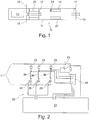
- FIG. 1 shows the schematic structure of an inhaler 10, for example, an electronic cigarette product.
- the inhaler comprises a substantially rod-shaped or cylindrical housing 11 with a mouth end 15 and one or more air inlet openings 16.
- the mouth end 15 designates the end at which the user pulls for the purpose of inhalation.
- an air channel is provided, which is passable by an air flow 17.
- the inhaler 10 is subjected to a negative pressure, as a result of which an air flow 17 in the air channel is established between the air inlet openings 16 and the mouth end 15.
- the air inlet openings 16 may be arranged on the shell side of the housing 11. Additionally or alternatively, at least one air inlet opening 16 may be provided at the end of the inhaler 10, which is opposite to the mouth end 15.
- the air stream 17 passes through an evaporator unit 20 arranged in the housing 11.
- the evaporator unit 20 is provided with liquid from a liquid reservoir 12 and has at least one heating element 36.
- the inhaler 10 comprises the liquid reservoir 12, which accommodates the liquid to be evaporated.
- An advantageous volume of the liquid reservoir 12 is in the range of 0.1-5 ml, preferably between 0.5-3 ml, more preferably between 0.7-2 ml or 1.5 ml.
- the liquid reservoir 12 preferably has a closed surface and is preferably a flexible bag. The liquid supply advantageously results from the evaporated liquid quantity.
- the evaporator unit 20 is supplied with liquid from the liquid storage 12 and electrically controlled to evaporate the liquid and add it to the air flow 17 in the form of gas and / or aerosol.
- the evaporator unit 20 is disposed in the housing 11 in an axial heating section.
- the amount of aerosol generated in the evaporator unit 20 can be changed both by changing the applied voltage and by the number of heating elements 36 used in parallel.
- an electrical voltage may be pulsed, oscillating or applied to the heating elements 36 by pulse width modulation.
- the characteristic of the voltage for example the amplitude and / or the frequency spectrum, can be advantageously adjusted over time or by adjustment of the user of the inhaler 10.
- the inhaler 10 comprises an electronic unit 14, which is in communication with a power source 27 and can perform measurement, control, regulation, data processing and / or data transfer.
- the electronic unit 14 advantageously comprises an electronic control device 21, in particular a microprocessor or microcontroller.
- the electronic unit 14 may preferably include an interface configured to output data to the user of the inhaler 10 and / or to have data entered by the user of the inhaler 10.
- a smoker can choose their favorite setting via their smartphone and Bluetooth connectivity and share it via social networks, make recommendations, and statistically evaluate their data and user behavior.
- the data preferably comprise data about the at least one heating element 36, the control frequencies, the level the liquid storage 12, the power source 27 and / or diagnostic and error data.
- the power source 27 may be a disposable electrochemical battery or a rechargeable electrochemical battery, e.g. a Lilon battery or a Li-battery.
- a step-up converter can be, starting from, for example, a lithium battery with 2.7-4.1 V, variable, adapted to the heating elements 36 voltages up to, for example 43 V, preferably 5-15 V, particularly preferably 2.7-15 V. , more preferably 3.6-6V, generate.
- the current source 27 serves to supply all active electrical components in the inhaler 10 electrically.
- the inhaler 10 is preferably modular and divided into at least one consumer unit and at least one reusable unit.
- the evaporator unit 20 may be a replaceable cartridge, or part of such a cartridge.
- the main body of the inhaler 10 may be reusable.
- the electronic unit 14 and / or the current source 27 are preferably connected via an interface with the evaporator unit 20.
- the power source 27 and / or the liquid storage 12 can be arranged in a consumption unit and intended for one-way use or arranged for reusable consumption in a reusable unit in the housing 11.
- the evaporator unit 20 can be used in electronic cigarette products as well as in medical inhalers. In addition to use in rod-shaped electronic cigarette products, the evaporator unit 20 can be used in electronic pipes, shishas or other products in which a liquid is to be evaporated from a liquid reservoir 12.
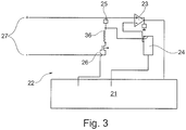
- FIG. 2 Fig. 12 shows a circuit diagram for a preferred embodiment of the inhaler 10 with, for example, three heating elements 36. In other embodiments, not shown, the number of heating elements 36 is more or less than three.
- the inhaler 10 includes a driving and measuring device 22, which is advantageously supplied by the electronic unit 14 by the power source 27 with electric current.
- the driving and measuring device 22 is controlled by the electronic control device 21.
- the drive and measuring device 22 comprises an operational amplifier 23, a switching device 24, at least one reference resistor 25 and at least one transistor 26.
- Preferably, for each heating element 36 is a reference resistor 25 connected in series (shunt) and a likewise connected in series thereto transistor 26th intended.
- the electronic unit 14 comprises the operational amplifier 23, the switching device 24, the reference resistor (s) 25 and / or the transistor (s) 26.
- the electronic control device 21 is adapted to detect a pull by the consumer by means of a suitable sensor, for example by means of a pressure sensor, and consequently to control the heating elements 36 in the evaporator unit 20 in order to heat the liquid to a suitable temperature.
- the electronic control unit 21 is connected to the transistors 26 and can control them independently of each other to independently control the heating elements 36 corresponding to the transistors 26.
- the electronic control device 21 is connected to the switching device 24 and the operational amplifier 23 as in FIG FIG. 2 shown connected to realize resistance measurements of the heating elements 36. Further sensors for the measurement of temperatures, pressures, and other variables for describing the operating state can be contained in the drive and measurement device 22 and coupled to the electronic control device 21.
- the operational amplifier 23 (current shunt monitor) is connected to the control unit 21, a ground, a positive pole, the reference resistor 25 and the switching device 24 and serves, for example, to measure the voltage drop between one of the reference resistors 25 and the voltage source 27.
- An amplified measurement result is the operational amplifier 23 to the control unit 21 on where the data processing is done to determine the measured resistance of the corresponding heating element 36.
- the switching device 24 is controlled by the control unit 21 and preferably sets one of the reference resistors 25 as the reference resistor 25 to be measured. Preferably, an electrical connection is made with the switching device 24 between the heating element 36 and the associated reference resistor 25.
- the switching device 24 preferably has a switch for each reference resistor 25 to be measured, in order to enable targeted measurement.
- the reference resistors 25 are preferably ohmic resistors.
- Each heating element 36 has a reference resistor 25 for current measurement.
- the transistors 26 are preferably designed as field-effect transistors (FET) and serve to control and regulate the heating elements 36. Each heating element 36 can be controlled via an associated transistor 26.
- FET field-effect transistors
- a suitable circuit can be integrated in addition to the individual control of the heating elements 36 and control mechanisms. In this way, monitoring and control of the evaporator unit 20 succeeds. Measurements can be made when switching on, off and / or during a train, but with the heating voltage switched off, for example every 10-1000 ms per channel, preferably 20-500 ms, particularly preferably 250 -400 ms. By multiplexing and modulating the signals onto a carrier signal, the amount of data can be reduced.
- the obtained current data of the individual heating elements 36 correlate with their resistance.
- the resistance clearly correlates with the temperature of the respective heating element 36.
- resistance and temperature information can be used to control and regulate the heating elements 36.
- a detailed error detection allows the detection of, for example, incorrect, too little or too much liquid or a defective heating element 36; an accurate state detection taking into account the known during the heating process thermodynamic state and the composition of the liquid is possible.
- thermometers preferably thermometers, humidity and / or pressure sensors to accurately characterize the operating state of the evaporator 20 and / or the heating elements 36.
- the heating elements 36 are preferably implemented as ohmic resistors and as a microsystem unit (e.g., MEMS).
- the design as a microsystem unit is particularly advantageous because of its very fine structures in the micron range and the associated thermal properties.
- the microsystem heating elements 36 are preferably made of a semiconductor material, for example doped silicon. This is inert and has no catalytic effect and the heating element 36 can thus be made particularly small, reproducible and stable.
- a temperature-variable resistance of, for example, 0.1-20 ohms, preferably 0.5-1.5 ohms, can be set.
- a temperature-dependent NTC or PTC behavior of the resistance of the heating elements 36 can be achieved, i. the resistance decreases or increases with increasing temperature.
- the heating elements 36 are connected to the liquid storage 12. For example, the liquid is conveyed capillary into a pore structure of the heating elements 36. If the heating elements 36 are heated to a temperature above a boiling temperature of a component of the liquid, evaporation takes place on the surface of the heating elements 36.
- the structure and surface of the heating elements 36 may, for example, also be based on bionic structures, such as tracheae.
- a capillary barrier for air from one side and liquid from the other side can be formed.
- the Heater structures are disposed along the air-to-liquid interface, and upon reaching a boiling temperature, the vaporized liquid may pass through the heater structure and be supplied to the airflow 17.
- the heating elements 36 preferably each have a layer structure, wherein in each case a heating element 36 has an area of preferably 0.25-6 mm 2 , particularly preferably 0.5-3 mm 2 .
- the total area of all heating elements 36 is preferably 0.2-1 cm 2 , more preferably 0.3-0.8 cm 2 , and a preferred layer thickness is in the range of 3-400 ⁇ m in order to achieve an optimum ratio to the liquid volume to be evaporated, depending on the heating surface ,
- the pores of the heater structure for example, have a diameter between 10-100 microns, preferably between 15-50 microns.
- the design of the heating elements 36 as a microsystem unit offers the possibility of influencing the amount of steam at the same applied average (evaporative) power by changing the drive frequency. This allows a particularly efficient and energy-saving steam generation by the heating elements 36. If the heating element 36 is driven at a certain frequency, ie heated, the proportion of the heating power brought into the evaporation increases with increasing frequency at the same average heating power up to an optimum. Thus, higher vapor levels are to be expected at higher frequencies as the resulting vaporization efficiency increases. The optimization of the energy input leads incidentally to a reduced power consumption.
- a change in the aerosol quality with the drive frequency of the heating elements 36 can furthermore be observed.
- a finer droplet size distribution can be determined, i. the distribution of droplet size shifts in favor of a smaller droplet size. This is due to a, with increasing frequency improved entry of the heat in the liquid to be evaporated. It is suitably pulsed or chosen a sufficient frequency that the heat of the heating element 36 can go into the liquid and without that losses due to too high energy input at too high a frequency (short pulse duration) or too strong cooling at too low a frequency (long Pulse duration).
- the heating elements 36 are designed as a microsystem unit and are able to follow the rapid change of energy input with its Schundtemperatur, i. have only a low thermal inertia. In contrast to a spiral or lattice structure, the heating elements 36 have a much higher cutoff frequency.
- FIG. 3 shows a circuit diagram for a preferred embodiment of the inhaler 10 with, for example, a heating element 36th
- the inhaler 10 comprises a driving and measuring device 22, which is advantageously comprised by the electronic unit 14 and is supplied with electric current by the current source 27.
- the driving and measuring device 22 is controlled by the electronic control device 21.
- the driving and measuring device 22 comprises an operational amplifier 23, a switching device 24, a reference resistor 25 and a transistor 26.
- the switching device 24 may be recessed with the use of only one heating element 36 in order to allow a simpler and more cost-effective design.
- the heating element 36 can be subjected to different and changeable drive frequencies. Both a superposition of different drive signals as well as a temporal change and / or modulation are conceivable in order to achieve a desired droplet size distribution.
- FIG. 4 shows an example of the time course of the heating voltage U H , which is applied to the heating element 36.
- the heating element 36 is heated in this embodiment, depending on the time t with pulses 32.
- a period 33 is subdivided into an evaporation phase 30 and a subsequent phase 31.
- a heating voltage U H is applied to the heating element 36 and allows evaporation of the liquid located on and / or on the heating element 36.
- the follow-up phase 31 preferably no heating voltage is applied to the heating element 36.
- an evaporation phase 30 takes place, the length of which is defined by the duty cycle.
- 33 different heating elements 36 can be measured sequentially during a period 33 and / or a shorter fraction of a period. With a suitable period duration 33, it is also possible to carry out a plurality of measurements, controls, controls and / or checks on different heating elements 36. In a preferred embodiment, at regular intervals to the controller, Regulation, control and / or data processing simplified.
- the heating power in the form of other alternating currents, periodic and aperiodic gradients is conceivable.
- the period 33 changes in a preferred embodiment over the duration of the operation and / or is preferably adjustable.
- Each heating element 36 can be heated identically or differently.
- FIG. 5 shows an example of the timing of the drive frequency f, which is applied to the heating element 36.
- the drive frequency f increases over the course of time t over the duration 42.
- the duration 42 can be given for example by the discharge duration of the liquid reservoir 12.
- the broken time axis makes it clear that the emptying time in this example should not be limited to the illustrated number of five trains 10.
- the drive frequency f is constant over a train 40.
- the heating power to the heating element 36 follows, for example, during a train to in FIG. 4 illustrated course.
- the individual trains 40 are interrupted by pauses 41 in which measurement, control, regulation and / or control of the operating state can take place. From train 40 to train 40, the driving frequency f increases over time t and, over time t, allows ever smaller droplets to be generated, for example to homogenize smoking experience and nicotine administration. Depending on the application, other temporal characteristics of the frequency are conceivable.
Landscapes
- Catching Or Destruction (AREA)
- Medicinal Preparation (AREA)
- Measurement Of The Respiration, Hearing Ability, Form, And Blood Characteristics Of Living Organisms (AREA)
- Special Spraying Apparatus (AREA)
- Sampling And Sample Adjustment (AREA)
Applications Claiming Priority (1)
| Application Number | Priority Date | Filing Date | Title |
|---|---|---|---|
| DE102017119521.1A DE102017119521A1 (de) | 2017-08-25 | 2017-08-25 | Verdampfereinheit für einen Inhalator und Verfahren zum Steuern einer Verdampfereinheit |
Publications (3)
| Publication Number | Publication Date |
|---|---|
| EP3446579A1 true EP3446579A1 (fr) | 2019-02-27 |
| EP3446579B1 EP3446579B1 (fr) | 2022-10-05 |
| EP3446579B8 EP3446579B8 (fr) | 2023-01-04 |
Family
ID=63371560
Family Applications (1)
| Application Number | Title | Priority Date | Filing Date |
|---|---|---|---|
| EP18190453.3A Active EP3446579B8 (fr) | 2017-08-25 | 2018-08-23 | Inhalateur et procédé de commande d'un inhalateur |
Country Status (6)
| Country | Link |
|---|---|
| US (1) | US20190059446A1 (fr) |
| EP (1) | EP3446579B8 (fr) |
| JP (1) | JP7252722B2 (fr) |
| KR (1) | KR102699812B1 (fr) |
| CN (1) | CN109419045B (fr) |
| DE (1) | DE102017119521A1 (fr) |
Cited By (1)
| Publication number | Priority date | Publication date | Assignee | Title |
|---|---|---|---|---|
| WO2022253734A1 (fr) * | 2021-06-02 | 2022-12-08 | Körber Technologies Gmbh | Dispositif de vaporisation pour inhalateur |
Families Citing this family (15)
| Publication number | Priority date | Publication date | Assignee | Title |
|---|---|---|---|---|
| US12599174B2 (en) * | 2018-05-10 | 2026-04-14 | Rai Strategic Holdings, Inc. | Control component for segmented heating in an aerosol delivery device |
| WO2020092245A1 (fr) * | 2018-10-29 | 2020-05-07 | Zorday IP, LLC | Cigarette électronique compatible avec un réseau |
| EP3711572A1 (fr) | 2019-03-22 | 2020-09-23 | Nerudia Limited | Système de substitution du tabac |
| DE102019114473A1 (de) | 2019-05-29 | 2020-12-03 | Hauni Maschinenbau Gmbh | Verdampfungsvorrichtung für einen elektrischen Inhalator |
| JP7274661B2 (ja) * | 2019-07-02 | 2023-05-16 | イーエム-テック・カンパニー・リミテッド | 携帯用エアロゾル発生装置及びその運用方法 |
| KR102477075B1 (ko) * | 2019-07-02 | 2022-12-13 | 주식회사 이엠텍 | 휴대용 에어로졸 발생장치 및 그 운용방법 |
| WO2021053229A1 (fr) | 2019-09-20 | 2021-03-25 | Nerudia Limited | Appareil de substitution pour fumeurs |
| JP6667708B1 (ja) | 2019-10-24 | 2020-03-18 | 日本たばこ産業株式会社 | エアロゾル吸引器の電源ユニット |
| JP6667709B1 (ja) * | 2019-10-24 | 2020-03-18 | 日本たばこ産業株式会社 | エアロゾル吸引器の電源ユニット |
| US12520880B2 (en) | 2021-01-18 | 2026-01-13 | Altria Client Services Llc | Heat-not-burn (HNB) aerosol-generating devices including energy based heater control, and methods of controlling a heater |
| WO2022164115A1 (fr) | 2021-01-26 | 2022-08-04 | Kt&G Corporation | Dispositif de génération d'aérosol |
| WO2022208834A1 (fr) * | 2021-04-01 | 2022-10-06 | 日本たばこ産業株式会社 | Dispositif de commande, dispositif terminal et procédé de traitement d'informations |
| CN115462563A (zh) * | 2021-06-10 | 2022-12-13 | 深圳市合元科技有限公司 | 电子雾化装置、电源机构及控制方法 |
| KR102625768B1 (ko) * | 2021-06-14 | 2024-01-16 | 주식회사 케이티앤지 | 에어로졸 생성 장치 및 그 제어 방법 |
| KR20230130367A (ko) * | 2022-03-03 | 2023-09-12 | 주식회사 케이티앤지 | 에어로졸 생성 방법 및 그 방법을 수행하는 전자 장치 |
Citations (5)
| Publication number | Priority date | Publication date | Assignee | Title |
|---|---|---|---|---|
| US6040560A (en) * | 1996-10-22 | 2000-03-21 | Philip Morris Incorporated | Power controller and method of operating an electrical smoking system |
| US20130340750A1 (en) * | 2010-12-03 | 2013-12-26 | Philip Morris Products S.A. | Electrically Heated Aerosol Generating System Having Improved Heater Control |
| US20160007653A1 (en) * | 2014-07-11 | 2016-01-14 | Xiang Zheng Tu | MEMS Vaporizer |
| US20160021934A1 (en) * | 2014-07-24 | 2016-01-28 | Edmond J. Cadieux | Electronic vaping device and components thereof |
| EP3170413A1 (fr) * | 2015-11-19 | 2017-05-24 | Fontem Holdings 1 B.V. | Dispositif à fumer électronique à éléments de chauffage fonctionnant de manière non simultanée |
Family Cites Families (20)
| Publication number | Priority date | Publication date | Assignee | Title |
|---|---|---|---|---|
| EP2143346A1 (fr) | 2008-07-08 | 2010-01-13 | Philip Morris Products S.A. | Système de capteur de flux |
| US9999250B2 (en) | 2010-05-15 | 2018-06-19 | Rai Strategic Holdings, Inc. | Vaporizer related systems, methods, and apparatus |
| EP2468117A1 (fr) | 2010-12-24 | 2012-06-27 | Philip Morris Products S.A. | Système de génération d'aérosol disposant de supports pour déterminer la déplétion d'un substrat liquide |
| GB2491358A (en) * | 2011-05-31 | 2012-12-05 | British American Tobacco Co | Smoking device for generating an aerosol |
| US8881737B2 (en) | 2012-09-04 | 2014-11-11 | R.J. Reynolds Tobacco Company | Electronic smoking article comprising one or more microheaters |
| TWI608805B (zh) | 2012-12-28 | 2017-12-21 | 菲利浦莫里斯製品股份有限公司 | 加熱型氣溶膠產生裝置及用於產生具有一致性質的氣溶膠之方法 |
| US9423152B2 (en) | 2013-03-15 | 2016-08-23 | R. J. Reynolds Tobacco Company | Heating control arrangement for an electronic smoking article and associated system and method |
| EP3831230B1 (fr) * | 2013-05-23 | 2025-03-12 | Altria Client Services LLC | Application de marketing numérique destinée à des utilisateurs de cigarettes électroniques |
| CN203467678U (zh) * | 2013-09-27 | 2014-03-12 | 向智勇 | 一种吸烟信号产生装置及电子烟 |
| RU2629878C1 (ru) * | 2013-09-30 | 2017-09-04 | Джапан Тобакко Инк. | Ароматический ингалятор негорящего типа |
| EP3076806B1 (fr) * | 2013-11-21 | 2021-08-25 | Avanzato Technology Corp. | Commande améliorée de vaporisation et dosage pour un inhalateur à vaporiseur électronique |
| CA2931577A1 (fr) * | 2013-12-11 | 2015-06-18 | Jt International S.A. | Systeme de chauffage et procede pour chauffer un dispositif d'inhalateur |
| US10081531B2 (en) | 2014-02-28 | 2018-09-25 | Beyond Twenty Ltd. | Electronic vaporiser system |
| GB201410171D0 (en) * | 2014-06-09 | 2014-07-23 | Nicoventures Holdings Ltd | Electronic vapour provision system |
| WO2016029225A1 (fr) * | 2014-08-22 | 2016-02-25 | Fontem Holdings 2 B.V. | Procédé, système et dispositif de commande d'un élément chauffant |
| WO2016075747A1 (fr) | 2014-11-10 | 2016-05-19 | 日本たばこ産業株式会社 | Inhalateur d'arôme sans combustion et emballage associé |
| PL3066940T3 (pl) * | 2015-03-13 | 2020-11-16 | Fontem Holdings 1 B.V. | Element wytwarzający aerozol dla elektronicznego urządzenia do palenia i elektroniczne urządzenie do palenia |
| WO2016175320A1 (fr) | 2015-04-30 | 2016-11-03 | 日本たばこ産業株式会社 | Appareil d'aspiration d'arôme sans combustion |
| WO2017085242A1 (fr) * | 2015-11-19 | 2017-05-26 | Philip Morris Products S.A. | Dispositif de chauffage à induction pour un substrat de formation d'aérosol |
| CN106343617B (zh) * | 2016-11-30 | 2019-04-30 | 广州周立功单片机科技有限公司 | 电子烟控制方法、装置和电子烟 |
-
2017
- 2017-08-25 DE DE102017119521.1A patent/DE102017119521A1/de active Pending
-
2018
- 2018-08-21 KR KR1020180097603A patent/KR102699812B1/ko active Active
- 2018-08-23 EP EP18190453.3A patent/EP3446579B8/fr active Active
- 2018-08-24 US US16/111,913 patent/US20190059446A1/en not_active Abandoned
- 2018-08-24 CN CN201810972853.XA patent/CN109419045B/zh active Active
- 2018-08-24 JP JP2018156891A patent/JP7252722B2/ja active Active
Patent Citations (5)
| Publication number | Priority date | Publication date | Assignee | Title |
|---|---|---|---|---|
| US6040560A (en) * | 1996-10-22 | 2000-03-21 | Philip Morris Incorporated | Power controller and method of operating an electrical smoking system |
| US20130340750A1 (en) * | 2010-12-03 | 2013-12-26 | Philip Morris Products S.A. | Electrically Heated Aerosol Generating System Having Improved Heater Control |
| US20160007653A1 (en) * | 2014-07-11 | 2016-01-14 | Xiang Zheng Tu | MEMS Vaporizer |
| US20160021934A1 (en) * | 2014-07-24 | 2016-01-28 | Edmond J. Cadieux | Electronic vaping device and components thereof |
| EP3170413A1 (fr) * | 2015-11-19 | 2017-05-24 | Fontem Holdings 1 B.V. | Dispositif à fumer électronique à éléments de chauffage fonctionnant de manière non simultanée |
Cited By (1)
| Publication number | Priority date | Publication date | Assignee | Title |
|---|---|---|---|---|
| WO2022253734A1 (fr) * | 2021-06-02 | 2022-12-08 | Körber Technologies Gmbh | Dispositif de vaporisation pour inhalateur |
Also Published As
| Publication number | Publication date |
|---|---|
| CN109419045A (zh) | 2019-03-05 |
| KR20190022360A (ko) | 2019-03-06 |
| EP3446579B1 (fr) | 2022-10-05 |
| JP2019037226A (ja) | 2019-03-14 |
| JP7252722B2 (ja) | 2023-04-05 |
| CN109419045B (zh) | 2024-05-07 |
| KR102699812B1 (ko) | 2024-08-29 |
| EP3446579B8 (fr) | 2023-01-04 |
| US20190059446A1 (en) | 2019-02-28 |
| DE102017119521A1 (de) | 2019-02-28 |
Similar Documents
| Publication | Publication Date | Title |
|---|---|---|
| EP3446579B1 (fr) | Inhalateur et procédé de commande d'un inhalateur | |
| DE102017111435B4 (de) | Verdampfereinheit für einen Inhalator und Verfahren zum Steuern einer Verdampfereinheit | |
| EP3886619A1 (fr) | Procédé et dispositif pour le réglage de température d'un vaporisateur pour un inhalateur, en particulier pour un produit de cigarette électronique | |
| EP2574247B1 (fr) | Feuille chauffante électrique perméable pour l'évaporation de liquides à partir d'embouts buccaux à usage unique avec membranes d'évaporation | |
| EP3496792B1 (fr) | Méthode de commande d'un inhalateur | |
| EP4026440B1 (fr) | Inhalateur | |
| EP3694349B2 (fr) | Inhalateur, notamment produit cigarette électronique | |
| DE69731980T2 (de) | Leistungsregler und verfahren zum betreiben eines elektrischen rauchsystems | |
| DE102017111119A1 (de) | Verdampfereinheit für einen Inhalator | |
| EP3534734A1 (fr) | Unité d'évaporation pour un inhalateur et procédé de commande d'une unité d'évaporation | |
| DE102012112977A1 (de) | Atem-Analysesystem auf Ionengrundlage | |
| EP3372096A1 (fr) | Unité d'évaporation pour un inhalateur | |
| DE102020110258B4 (de) | Inhalator | |
| WO2018115109A1 (fr) | Unité d'évaporation pour un inhalateur et procédé de commande d'une unité d'évaporation | |
| EP3972435B1 (fr) | Procédé de régulation de l'évaporation d'un vaporisateur dans un inhalateur | |
| DE102022110722A1 (de) | Vorrichtung zum Transferieren von einem Wirkstoff in eine Gasphase |
Legal Events
| Date | Code | Title | Description |
|---|---|---|---|
| PUAI | Public reference made under article 153(3) epc to a published international application that has entered the european phase |
Free format text: ORIGINAL CODE: 0009012 |
|
| STAA | Information on the status of an ep patent application or granted ep patent |
Free format text: STATUS: THE APPLICATION HAS BEEN PUBLISHED |
|
| AK | Designated contracting states |
Kind code of ref document: A1 Designated state(s): AL AT BE BG CH CY CZ DE DK EE ES FI FR GB GR HR HU IE IS IT LI LT LU LV MC MK MT NL NO PL PT RO RS SE SI SK SM TR |
|
| AX | Request for extension of the european patent |
Extension state: BA ME |
|
| STAA | Information on the status of an ep patent application or granted ep patent |
Free format text: STATUS: REQUEST FOR EXAMINATION WAS MADE |
|
| 17P | Request for examination filed |
Effective date: 20190731 |
|
| RBV | Designated contracting states (corrected) |
Designated state(s): AL AT BE BG CH CY CZ DE DK EE ES FI FR GB GR HR HU IE IS IT LI LT LU LV MC MK MT NL NO PL PT RO RS SE SI SK SM TR |
|
| REG | Reference to a national code |
Ref country code: DE Ref legal event code: R079 Ref document number: 502018010761 Country of ref document: DE Free format text: PREVIOUS MAIN CLASS: A24F0047000000 Ipc: A24F0040460000 |
|
| GRAP | Despatch of communication of intention to grant a patent |
Free format text: ORIGINAL CODE: EPIDOSNIGR1 |
|
| STAA | Information on the status of an ep patent application or granted ep patent |
Free format text: STATUS: GRANT OF PATENT IS INTENDED |
|
| RIC1 | Information provided on ipc code assigned before grant |
Ipc: A24F 40/53 20200101ALI20220214BHEP Ipc: A24F 40/46 20200101AFI20220214BHEP |
|
| INTG | Intention to grant announced |
Effective date: 20220321 |
|
| GRAS | Grant fee paid |
Free format text: ORIGINAL CODE: EPIDOSNIGR3 |
|
| GRAA | (expected) grant |
Free format text: ORIGINAL CODE: 0009210 |
|
| STAA | Information on the status of an ep patent application or granted ep patent |
Free format text: STATUS: THE PATENT HAS BEEN GRANTED |
|
| AK | Designated contracting states |
Kind code of ref document: B1 Designated state(s): AL AT BE BG CH CY CZ DE DK EE ES FI FR GB GR HR HU IE IS IT LI LT LU LV MC MK MT NL NO PL PT RO RS SE SI SK SM TR |
|
| REG | Reference to a national code |
Ref country code: GB Ref legal event code: FG4D Free format text: NOT ENGLISH |
|
| REG | Reference to a national code |
Ref country code: CH Ref legal event code: EP |
|
| REG | Reference to a national code |
Ref country code: AT Ref legal event code: REF Ref document number: 1522192 Country of ref document: AT Kind code of ref document: T Effective date: 20221015 |
|
| REG | Reference to a national code |
Ref country code: IE Ref legal event code: FG4D Free format text: LANGUAGE OF EP DOCUMENT: GERMAN |
|
| REG | Reference to a national code |
Ref country code: DE Ref legal event code: R081 Ref document number: 502018010761 Country of ref document: DE Owner name: KOERBER TECHNOLOGIES GMBH, DE Free format text: FORMER OWNER: HAUNI MASCHINENBAU GMBH, 21033 HAMBURG, DE Ref country code: DE Ref legal event code: R096 Ref document number: 502018010761 Country of ref document: DE |
|
| REG | Reference to a national code |
Ref country code: CH Ref legal event code: PK Free format text: BERICHTIGUNG B8 |
|
| RAP4 | Party data changed (patent owner data changed or rights of a patent transferred) |
Owner name: KOERBER TECHNOLOGIES GMBH |
|
| REG | Reference to a national code |
Ref country code: LT Ref legal event code: MG9D |
|
| REG | Reference to a national code |
Ref country code: NL Ref legal event code: MP Effective date: 20221005 |
|
| PG25 | Lapsed in a contracting state [announced via postgrant information from national office to epo] |
Ref country code: NL Free format text: LAPSE BECAUSE OF FAILURE TO SUBMIT A TRANSLATION OF THE DESCRIPTION OR TO PAY THE FEE WITHIN THE PRESCRIBED TIME-LIMIT Effective date: 20221005 |
|
| PG25 | Lapsed in a contracting state [announced via postgrant information from national office to epo] |
Ref country code: SE Free format text: LAPSE BECAUSE OF FAILURE TO SUBMIT A TRANSLATION OF THE DESCRIPTION OR TO PAY THE FEE WITHIN THE PRESCRIBED TIME-LIMIT Effective date: 20221005 Ref country code: PT Free format text: LAPSE BECAUSE OF FAILURE TO SUBMIT A TRANSLATION OF THE DESCRIPTION OR TO PAY THE FEE WITHIN THE PRESCRIBED TIME-LIMIT Effective date: 20230206 Ref country code: NO Free format text: LAPSE BECAUSE OF FAILURE TO SUBMIT A TRANSLATION OF THE DESCRIPTION OR TO PAY THE FEE WITHIN THE PRESCRIBED TIME-LIMIT Effective date: 20230105 Ref country code: LT Free format text: LAPSE BECAUSE OF FAILURE TO SUBMIT A TRANSLATION OF THE DESCRIPTION OR TO PAY THE FEE WITHIN THE PRESCRIBED TIME-LIMIT Effective date: 20221005 Ref country code: FI Free format text: LAPSE BECAUSE OF FAILURE TO SUBMIT A TRANSLATION OF THE DESCRIPTION OR TO PAY THE FEE WITHIN THE PRESCRIBED TIME-LIMIT Effective date: 20221005 Ref country code: ES Free format text: LAPSE BECAUSE OF FAILURE TO SUBMIT A TRANSLATION OF THE DESCRIPTION OR TO PAY THE FEE WITHIN THE PRESCRIBED TIME-LIMIT Effective date: 20221005 |
|
| PG25 | Lapsed in a contracting state [announced via postgrant information from national office to epo] |
Ref country code: RS Free format text: LAPSE BECAUSE OF FAILURE TO SUBMIT A TRANSLATION OF THE DESCRIPTION OR TO PAY THE FEE WITHIN THE PRESCRIBED TIME-LIMIT Effective date: 20221005 Ref country code: PL Free format text: LAPSE BECAUSE OF FAILURE TO SUBMIT A TRANSLATION OF THE DESCRIPTION OR TO PAY THE FEE WITHIN THE PRESCRIBED TIME-LIMIT Effective date: 20221005 Ref country code: LV Free format text: LAPSE BECAUSE OF FAILURE TO SUBMIT A TRANSLATION OF THE DESCRIPTION OR TO PAY THE FEE WITHIN THE PRESCRIBED TIME-LIMIT Effective date: 20221005 Ref country code: IS Free format text: LAPSE BECAUSE OF FAILURE TO SUBMIT A TRANSLATION OF THE DESCRIPTION OR TO PAY THE FEE WITHIN THE PRESCRIBED TIME-LIMIT Effective date: 20230205 Ref country code: HR Free format text: LAPSE BECAUSE OF FAILURE TO SUBMIT A TRANSLATION OF THE DESCRIPTION OR TO PAY THE FEE WITHIN THE PRESCRIBED TIME-LIMIT Effective date: 20221005 Ref country code: GR Free format text: LAPSE BECAUSE OF FAILURE TO SUBMIT A TRANSLATION OF THE DESCRIPTION OR TO PAY THE FEE WITHIN THE PRESCRIBED TIME-LIMIT Effective date: 20230106 |
|
| REG | Reference to a national code |
Ref country code: DE Ref legal event code: R026 Ref document number: 502018010761 Country of ref document: DE |
|
| PLBI | Opposition filed |
Free format text: ORIGINAL CODE: 0009260 |
|
| PLAX | Notice of opposition and request to file observation + time limit sent |
Free format text: ORIGINAL CODE: EPIDOSNOBS2 |
|
| P01 | Opt-out of the competence of the unified patent court (upc) registered |
Effective date: 20230616 |
|
| PG25 | Lapsed in a contracting state [announced via postgrant information from national office to epo] |
Ref country code: SM Free format text: LAPSE BECAUSE OF FAILURE TO SUBMIT A TRANSLATION OF THE DESCRIPTION OR TO PAY THE FEE WITHIN THE PRESCRIBED TIME-LIMIT Effective date: 20221005 Ref country code: RO Free format text: LAPSE BECAUSE OF FAILURE TO SUBMIT A TRANSLATION OF THE DESCRIPTION OR TO PAY THE FEE WITHIN THE PRESCRIBED TIME-LIMIT Effective date: 20221005 Ref country code: EE Free format text: LAPSE BECAUSE OF FAILURE TO SUBMIT A TRANSLATION OF THE DESCRIPTION OR TO PAY THE FEE WITHIN THE PRESCRIBED TIME-LIMIT Effective date: 20221005 Ref country code: DK Free format text: LAPSE BECAUSE OF FAILURE TO SUBMIT A TRANSLATION OF THE DESCRIPTION OR TO PAY THE FEE WITHIN THE PRESCRIBED TIME-LIMIT Effective date: 20221005 Ref country code: CZ Free format text: LAPSE BECAUSE OF FAILURE TO SUBMIT A TRANSLATION OF THE DESCRIPTION OR TO PAY THE FEE WITHIN THE PRESCRIBED TIME-LIMIT Effective date: 20221005 |
|
| 26 | Opposition filed |
Opponent name: G.D S.P.A. Effective date: 20230704 |
|
| PG25 | Lapsed in a contracting state [announced via postgrant information from national office to epo] |
Ref country code: SK Free format text: LAPSE BECAUSE OF FAILURE TO SUBMIT A TRANSLATION OF THE DESCRIPTION OR TO PAY THE FEE WITHIN THE PRESCRIBED TIME-LIMIT Effective date: 20221005 Ref country code: AL Free format text: LAPSE BECAUSE OF FAILURE TO SUBMIT A TRANSLATION OF THE DESCRIPTION OR TO PAY THE FEE WITHIN THE PRESCRIBED TIME-LIMIT Effective date: 20221005 |
|
| PLBB | Reply of patent proprietor to notice(s) of opposition received |
Free format text: ORIGINAL CODE: EPIDOSNOBS3 |
|
| PG25 | Lapsed in a contracting state [announced via postgrant information from national office to epo] |
Ref country code: SI Free format text: LAPSE BECAUSE OF FAILURE TO SUBMIT A TRANSLATION OF THE DESCRIPTION OR TO PAY THE FEE WITHIN THE PRESCRIBED TIME-LIMIT Effective date: 20221005 |
|
| PG25 | Lapsed in a contracting state [announced via postgrant information from national office to epo] |
Ref country code: MC Free format text: LAPSE BECAUSE OF FAILURE TO SUBMIT A TRANSLATION OF THE DESCRIPTION OR TO PAY THE FEE WITHIN THE PRESCRIBED TIME-LIMIT Effective date: 20221005 |
|
| REG | Reference to a national code |
Ref country code: CH Ref legal event code: PL |
|
| PG25 | Lapsed in a contracting state [announced via postgrant information from national office to epo] |
Ref country code: MC Free format text: LAPSE BECAUSE OF FAILURE TO SUBMIT A TRANSLATION OF THE DESCRIPTION OR TO PAY THE FEE WITHIN THE PRESCRIBED TIME-LIMIT Effective date: 20221005 |
|
| PG25 | Lapsed in a contracting state [announced via postgrant information from national office to epo] |
Ref country code: LU Free format text: LAPSE BECAUSE OF NON-PAYMENT OF DUE FEES Effective date: 20230823 |
|
| PG25 | Lapsed in a contracting state [announced via postgrant information from national office to epo] |
Ref country code: LU Free format text: LAPSE BECAUSE OF NON-PAYMENT OF DUE FEES Effective date: 20230823 Ref country code: CH Free format text: LAPSE BECAUSE OF NON-PAYMENT OF DUE FEES Effective date: 20230831 |
|
| REG | Reference to a national code |
Ref country code: BE Ref legal event code: MM Effective date: 20230831 |
|
| REG | Reference to a national code |
Ref country code: IE Ref legal event code: MM4A |
|
| PG25 | Lapsed in a contracting state [announced via postgrant information from national office to epo] |
Ref country code: IT Free format text: LAPSE BECAUSE OF FAILURE TO SUBMIT A TRANSLATION OF THE DESCRIPTION OR TO PAY THE FEE WITHIN THE PRESCRIBED TIME-LIMIT Effective date: 20221005 |
|
| PG25 | Lapsed in a contracting state [announced via postgrant information from national office to epo] |
Ref country code: IE Free format text: LAPSE BECAUSE OF NON-PAYMENT OF DUE FEES Effective date: 20230823 |
|
| PG25 | Lapsed in a contracting state [announced via postgrant information from national office to epo] |
Ref country code: IE Free format text: LAPSE BECAUSE OF NON-PAYMENT OF DUE FEES Effective date: 20230823 |
|
| PG25 | Lapsed in a contracting state [announced via postgrant information from national office to epo] |
Ref country code: BE Free format text: LAPSE BECAUSE OF NON-PAYMENT OF DUE FEES Effective date: 20230831 |
|
| REG | Reference to a national code |
Ref country code: AT Ref legal event code: MM01 Ref document number: 1522192 Country of ref document: AT Kind code of ref document: T Effective date: 20230823 |
|
| PG25 | Lapsed in a contracting state [announced via postgrant information from national office to epo] |
Ref country code: AT Free format text: LAPSE BECAUSE OF NON-PAYMENT OF DUE FEES Effective date: 20230823 |
|
| PG25 | Lapsed in a contracting state [announced via postgrant information from national office to epo] |
Ref country code: AT Free format text: LAPSE BECAUSE OF NON-PAYMENT OF DUE FEES Effective date: 20230823 |
|
| PG25 | Lapsed in a contracting state [announced via postgrant information from national office to epo] |
Ref country code: BG Free format text: LAPSE BECAUSE OF FAILURE TO SUBMIT A TRANSLATION OF THE DESCRIPTION OR TO PAY THE FEE WITHIN THE PRESCRIBED TIME-LIMIT Effective date: 20221005 |
|
| PG25 | Lapsed in a contracting state [announced via postgrant information from national office to epo] |
Ref country code: BG Free format text: LAPSE BECAUSE OF FAILURE TO SUBMIT A TRANSLATION OF THE DESCRIPTION OR TO PAY THE FEE WITHIN THE PRESCRIBED TIME-LIMIT Effective date: 20221005 |
|
| PG25 | Lapsed in a contracting state [announced via postgrant information from national office to epo] |
Ref country code: CY Free format text: LAPSE BECAUSE OF FAILURE TO SUBMIT A TRANSLATION OF THE DESCRIPTION OR TO PAY THE FEE WITHIN THE PRESCRIBED TIME-LIMIT; INVALID AB INITIO Effective date: 20180823 |
|
| PG25 | Lapsed in a contracting state [announced via postgrant information from national office to epo] |
Ref country code: HU Free format text: LAPSE BECAUSE OF FAILURE TO SUBMIT A TRANSLATION OF THE DESCRIPTION OR TO PAY THE FEE WITHIN THE PRESCRIBED TIME-LIMIT; INVALID AB INITIO Effective date: 20180823 |
|
| PGFP | Annual fee paid to national office [announced via postgrant information from national office to epo] |
Ref country code: DE Payment date: 20250821 Year of fee payment: 8 |
|
| PGFP | Annual fee paid to national office [announced via postgrant information from national office to epo] |
Ref country code: GB Payment date: 20250827 Year of fee payment: 8 |
|
| PGFP | Annual fee paid to national office [announced via postgrant information from national office to epo] |
Ref country code: FR Payment date: 20250826 Year of fee payment: 8 |
|
| PG25 | Lapsed in a contracting state [announced via postgrant information from national office to epo] |
Ref country code: TR Free format text: LAPSE BECAUSE OF FAILURE TO SUBMIT A TRANSLATION OF THE DESCRIPTION OR TO PAY THE FEE WITHIN THE PRESCRIBED TIME-LIMIT Effective date: 20221005 |
|
| RDAF | Communication despatched that patent is revoked |
Free format text: ORIGINAL CODE: EPIDOSNREV1 |