EP3446584B1 - Verfahren zum herstellen eines schutzhelms und nach diesem verfahren hergestellter schutzhelm - Google Patents
Verfahren zum herstellen eines schutzhelms und nach diesem verfahren hergestellter schutzhelm Download PDFInfo
- Publication number
- EP3446584B1 EP3446584B1 EP18186059.4A EP18186059A EP3446584B1 EP 3446584 B1 EP3446584 B1 EP 3446584B1 EP 18186059 A EP18186059 A EP 18186059A EP 3446584 B1 EP3446584 B1 EP 3446584B1
- Authority
- EP
- European Patent Office
- Prior art keywords
- helmet body
- helmet
- outer shell
- filling point
- filling
- Prior art date
- Legal status (The legal status is an assumption and is not a legal conclusion. Google has not performed a legal analysis and makes no representation as to the accuracy of the status listed.)
- Active
Links
Images

Classifications
-
- B—PERFORMING OPERATIONS; TRANSPORTING
- B29—WORKING OF PLASTICS; WORKING OF SUBSTANCES IN A PLASTIC STATE IN GENERAL
- B29C—SHAPING OR JOINING OF PLASTICS; SHAPING OF MATERIAL IN A PLASTIC STATE, NOT OTHERWISE PROVIDED FOR; AFTER-TREATMENT OF THE SHAPED PRODUCTS, e.g. REPAIRING
- B29C39/00—Shaping by casting, i.e. introducing the moulding material into a mould or between confining surfaces without significant moulding pressure; Apparatus therefor
- B29C39/02—Shaping by casting, i.e. introducing the moulding material into a mould or between confining surfaces without significant moulding pressure; Apparatus therefor for making articles of definite length, i.e. discrete articles
- B29C39/10—Shaping by casting, i.e. introducing the moulding material into a mould or between confining surfaces without significant moulding pressure; Apparatus therefor for making articles of definite length, i.e. discrete articles incorporating preformed parts or layers, e.g. casting around inserts or for coating articles
-
- A—HUMAN NECESSITIES
- A42—HEADWEAR
- A42C—MANUFACTURING OR TRIMMING HEAD COVERINGS, e.g. HATS
- A42C2/00—Manufacturing helmets by processes not otherwise provided for
- A42C2/002—In-mould forming
-
- A—HUMAN NECESSITIES
- A42—HEADWEAR
- A42B—HATS; HEAD COVERINGS
- A42B3/00—Helmets; Helmet covers ; Other protective head coverings
- A42B3/04—Parts, details or accessories of helmets
- A42B3/0406—Accessories for helmets
-
- A—HUMAN NECESSITIES
- A42—HEADWEAR
- A42B—HATS; HEAD COVERINGS
- A42B3/00—Helmets; Helmet covers ; Other protective head coverings
- A42B3/04—Parts, details or accessories of helmets
- A42B3/0406—Accessories for helmets
- A42B3/042—Optical devices
-
- A—HUMAN NECESSITIES
- A42—HEADWEAR
- A42B—HATS; HEAD COVERINGS
- A42B3/00—Helmets; Helmet covers ; Other protective head coverings
- A42B3/04—Parts, details or accessories of helmets
- A42B3/0406—Accessories for helmets
- A42B3/0433—Detecting, signalling or lighting devices
- A42B3/044—Lighting devices, e.g. helmets with lamps
-
- A—HUMAN NECESSITIES
- A42—HEADWEAR
- A42B—HATS; HEAD COVERINGS
- A42B3/00—Helmets; Helmet covers ; Other protective head coverings
- A42B3/04—Parts, details or accessories of helmets
- A42B3/06—Impact-absorbing shells, e.g. of crash helmets
-
- A—HUMAN NECESSITIES
- A42—HEADWEAR
- A42B—HATS; HEAD COVERINGS
- A42B3/00—Helmets; Helmet covers ; Other protective head coverings
- A42B3/04—Parts, details or accessories of helmets
- A42B3/06—Impact-absorbing shells, e.g. of crash helmets
- A42B3/066—Impact-absorbing shells, e.g. of crash helmets specially adapted for cycling helmets, e.g. for soft shelled helmets
-
- A—HUMAN NECESSITIES
- A42—HEADWEAR
- A42B—HATS; HEAD COVERINGS
- A42B3/00—Helmets; Helmet covers ; Other protective head coverings
- A42B3/04—Parts, details or accessories of helmets
- A42B3/28—Ventilating arrangements
- A42B3/281—Air ducting systems
- A42B3/283—Air inlets or outlets, with or without closure shutters
-
- B—PERFORMING OPERATIONS; TRANSPORTING
- B29—WORKING OF PLASTICS; WORKING OF SUBSTANCES IN A PLASTIC STATE IN GENERAL
- B29C—SHAPING OR JOINING OF PLASTICS; SHAPING OF MATERIAL IN A PLASTIC STATE, NOT OTHERWISE PROVIDED FOR; AFTER-TREATMENT OF THE SHAPED PRODUCTS, e.g. REPAIRING
- B29C39/00—Shaping by casting, i.e. introducing the moulding material into a mould or between confining surfaces without significant moulding pressure; Apparatus therefor
- B29C39/003—Shaping by casting, i.e. introducing the moulding material into a mould or between confining surfaces without significant moulding pressure; Apparatus therefor characterised by the choice of material
-
- B—PERFORMING OPERATIONS; TRANSPORTING
- B29—WORKING OF PLASTICS; WORKING OF SUBSTANCES IN A PLASTIC STATE IN GENERAL
- B29C—SHAPING OR JOINING OF PLASTICS; SHAPING OF MATERIAL IN A PLASTIC STATE, NOT OTHERWISE PROVIDED FOR; AFTER-TREATMENT OF THE SHAPED PRODUCTS, e.g. REPAIRING
- B29C45/00—Injection moulding, i.e. forcing the required volume of moulding material through a nozzle into a closed mould; Apparatus therefor
- B29C45/0001—Injection moulding, i.e. forcing the required volume of moulding material through a nozzle into a closed mould; Apparatus therefor characterised by the choice of material
-
- B—PERFORMING OPERATIONS; TRANSPORTING
- B29—WORKING OF PLASTICS; WORKING OF SUBSTANCES IN A PLASTIC STATE IN GENERAL
- B29C—SHAPING OR JOINING OF PLASTICS; SHAPING OF MATERIAL IN A PLASTIC STATE, NOT OTHERWISE PROVIDED FOR; AFTER-TREATMENT OF THE SHAPED PRODUCTS, e.g. REPAIRING
- B29C45/00—Injection moulding, i.e. forcing the required volume of moulding material through a nozzle into a closed mould; Apparatus therefor
- B29C45/14—Injection moulding, i.e. forcing the required volume of moulding material through a nozzle into a closed mould; Apparatus therefor incorporating preformed parts or layers, e.g. injection moulding around inserts or for coating articles
- B29C45/14336—Coating a portion of the article, e.g. the edge of the article
-
- B—PERFORMING OPERATIONS; TRANSPORTING
- B29—WORKING OF PLASTICS; WORKING OF SUBSTANCES IN A PLASTIC STATE IN GENERAL
- B29C—SHAPING OR JOINING OF PLASTICS; SHAPING OF MATERIAL IN A PLASTIC STATE, NOT OTHERWISE PROVIDED FOR; AFTER-TREATMENT OF THE SHAPED PRODUCTS, e.g. REPAIRING
- B29C45/00—Injection moulding, i.e. forcing the required volume of moulding material through a nozzle into a closed mould; Apparatus therefor
- B29C45/14—Injection moulding, i.e. forcing the required volume of moulding material through a nozzle into a closed mould; Apparatus therefor incorporating preformed parts or layers, e.g. injection moulding around inserts or for coating articles
- B29C45/14778—Injection moulding, i.e. forcing the required volume of moulding material through a nozzle into a closed mould; Apparatus therefor incorporating preformed parts or layers, e.g. injection moulding around inserts or for coating articles the article consisting of a material with particular properties, e.g. porous, brittle
- B29C45/14795—Porous or permeable material, e.g. foam
-
- A—HUMAN NECESSITIES
- A42—HEADWEAR
- A42B—HATS; HEAD COVERINGS
- A42B3/00—Helmets; Helmet covers ; Other protective head coverings
- A42B3/04—Parts, details or accessories of helmets
- A42B3/28—Ventilating arrangements
-
- B—PERFORMING OPERATIONS; TRANSPORTING
- B29—WORKING OF PLASTICS; WORKING OF SUBSTANCES IN A PLASTIC STATE IN GENERAL
- B29K—INDEXING SCHEME ASSOCIATED WITH SUBCLASSES B29B, B29C OR B29D, RELATING TO MOULDING MATERIALS OR TO MATERIALS FOR MOULDS, REINFORCEMENTS, FILLERS OR PREFORMED PARTS, e.g. INSERTS
- B29K2025/00—Use of polymers of vinyl-aromatic compounds or derivatives thereof as moulding material
- B29K2025/04—Polymers of styrene
- B29K2025/06—PS, i.e. polystyrene
-
- B—PERFORMING OPERATIONS; TRANSPORTING
- B29—WORKING OF PLASTICS; WORKING OF SUBSTANCES IN A PLASTIC STATE IN GENERAL
- B29L—INDEXING SCHEME ASSOCIATED WITH SUBCLASS B29C, RELATING TO PARTICULAR ARTICLES
- B29L2031/00—Other particular articles
- B29L2031/48—Wearing apparel
- B29L2031/4807—Headwear
- B29L2031/4814—Hats
- B29L2031/4821—Helmets
Definitions
- the present invention relates to a method for producing a protective helmet, in particular a bicycle helmet, which has a shock-absorbing helmet body with a concave inside and a convex outside and an outer shell arranged on the outer side of the helmet body, with the steps of: placing the outer shell in a casting mold and filling it a casting material into the casting mold at at least one filling point in order to form the helmet body, wherein the casting material is bonded to an inside of the outer shell.
- the invention also relates to a protective helmet produced by this method.
- Such a protective helmet serves to protect the user against head injuries in the event of a fall or an impact of an object on the user's head.
- the protective helmet comprises a helmet body which has a generally concave-shaped inside facing the head of the user and a generally convex-shaped outside facing away from the head of the user.
- the protective helmet can have several ventilation openings which run through the outer shell and through the helmet body.
- the helmet body should absorb as much as possible the kinetic energy acting on the protective helmet in the event of an impact (impact or impact) through inelastic and / or elastic deformation.
- a belt fixing system can also be attached to the helmet body, by means of which the helmet body can be fixed to the head of the user and which can for example comprise several neck and chin straps.
- the protective helmet further comprises an outer shell which is arranged on the outer side of the helmet body and which, corresponding to the helmet body, can have a generally concave-shaped inner side and a generally convex-shaped outer side.
- the outer shell can also perform a protective function (e.g. shock absorption or reduction of the coefficient of friction for the protective helmet to slide along a rough surface), or it essentially only fulfills a decorative function.
- the outer shell is placed in a casting mold.
- a casting material is then poured into the casting mold at at least one filling point in order to form the helmet body, the casting material bonding to the inside of the outer shell.
- foaming of the casting material can be provided.
- the method can in particular also be carried out as an injection molding method in which the casting material (as an injection molding material) is filled or injected into the casting mold under pressure.
- a method for producing a protective helmet and a corresponding protective helmet which has a shock-absorbing helmet body, wherein a casting material is poured into a casting mold at at least one filling point around the To form helmet body, wherein the filling point is provided on the outside of the helmet body formed.
- the end EP 2 071 969 A2 and DE 92 04 816 U1 further manufacturing processes and corresponding protective helmets are known.
- the filling point for the casting material is provided on the outside of the helmet body formed, the outer shell having an exposure in the area of the filling point.
- the casting material is poured into the casting mold in accordance with inmold technology, while the outer shell of the protective helmet to be formed is already inserted into the casting mold.
- the casting material is poured into the casting mold at at least one filling point which is provided on the (convex) outside of the helmet body to be formed.
- the casting mold comprises at least one corresponding filling channel for the casting material.
- the mentioned filling point is that point on the outside of the helmet body to be formed or formed at which the filling channel of the casting mold opens.
- the outer shell In order to enable such a filling of the casting material on the outside of the helmet body or on the corresponding (concave) inner surface of the casting mold, the outer shell (inserted into the casting mold) has a clearance in the area of the mentioned filling point, i.e. an interruption such that immediately after the casting process and after removing the Helmet body and the outer shell from the mold exposes the filling point of the helmet body on the outside of the helmet body formed.
- At least one filling point for the casting material is also provided on the outside of the helmet body.
- Such a filling point on the surface of the helmet body forms a fundamentally perceptible disruption of the otherwise homogeneously producible appearance of the helmet body, which is why it is obvious to provide the filling point for the casting material on the (concave) inside of the helmet body, which when the protective helmet is used, the head of the Facing the user and is therefore not visible.
- at least one filling point is arranged on the outside of the helmet body, the shape of the helmet body is more flexible, since there are additional possibilities for filling the casting material into the casting mold at suitable positions.
- the filling point for the casting material can be arranged at a distance from an edge region of the helmet body formed. This enables the casting material to be distributed over a wide area within the casting mold.
- the casting material can be poured into the casting mold at several filling points, ie the casting mold can have several filling channels for the casting material.
- at least one of the plurality of filling points (in particular also each of the plurality of filling points) can be provided on the outside of the helmet body formed. This also makes it possible to achieve a homogeneous distribution of the casting material over a wide area within the casting mold, even with a complex shape.
- expanded polystyrene rigid foam can be provided as the casting material.
- the casting mold can be an injection mold, the casting material being an injection molding material which is filled into the injection mold under pressure.
- the exposure can be circumferentially closed, i.e. the outer shell surrounds the filling point of the helmet body circumferentially.
- the outer shell can at the same time enclose a ventilation opening in the helmet body.
- the outer shell of the protective helmet can be in one piece or in several pieces.
- the outer shell of the protective helmet can for example have a shell, in particular a film, made of polyvinyl chloride (PVC), polyethylene terephthalate (PET) or a polycarbonate (PC).
- a shell in particular a film, made of polyvinyl chloride (PVC), polyethylene terephthalate (PET) or a polycarbonate (PC).
- the outer side of the helmet body can be covered with a cover part in the area of the filling point.
- the cover part can in particular be a shell part which at least essentially corresponds to the appearance of the outer shell of the protective helmet.
- the corresponding shell part can correspond to the outer shell of the protective helmet in terms of material and / or color.
- the cover part in particular the shell part, can, however, also be formed from a different material than the outer shell of the protective helmet, for example from acrylonitrile-butadiene-styrene copolymer (ABS), polyethylene (PE), polypropylene (PP), aramid (especially Kevlar), Fiberglass or a combination thereof.
- ABS acrylonitrile-butadiene-styrene copolymer
- PE polyethylene
- PP polypropylene
- aramid especially Kevlar
- Fiberglass or a combination thereof.
- the cover part in particular the shell part, can also be additionally provided with a damping material, in particular with a damping material layer, which is, for example, foamed on or attached in some other way.
- a damping material layer which is, for example, foamed on or attached in some other way.
- This can be provided in particular in an embodiment in which the cover part, in particular the shell part, has additional or different damping properties or forms aerodynamically optimized surfaces.
- the cover part in particular the shell part, can have a receiving device - for example a fastening opening, a fastening recess or a fastening elevation - for receiving a helmet accessory, e.g. a lighting device or a camera.
- a receiving device - for example a fastening opening, a fastening recess or a fastening elevation - for receiving a helmet accessory, e.g. a lighting device or a camera.
- the attachment of the cover part to the helmet body and / or to the outer shell can be done, for example, by means of a latching connection or by gluing.
- the protective helmet has several ventilation openings which run through the outer shell and through the helmet body, the filling point provided on the outside of the helmet body being arranged on a boundary surface of one of the ventilation openings.
- the filling point for the casting material can be arranged set back relative to the generally convex surface of the helmet body, so that the filling point is visually less noticeable.
- the protective helmet can have a recess for receiving a helmet accessory, e.g. a lighting device or a camera, the filling point for the casting material provided on the outside of the helmet body being arranged on a boundary surface of the recess.
- a helmet accessory e.g. a lighting device or a camera
- the filling point for the casting material provided on the outside of the helmet body being arranged on a boundary surface of the recess.
- the object of the invention is also achieved by a protective helmet with the features of claim 6.
- Such a protective helmet has a shock-absorbing helmet body and an outer shell arranged on the outside of the helmet body and is produced by a method according to one of the embodiments described above, the surface of the helmet body having at least one filling point for the casting material forming the helmet body, the filling point is arranged on the outside of the helmet body, and wherein the outer shell has an exposure in the area of the filling point.
- the outside of the helmet body can be covered with a cover part of the type explained, in particular with a shell part, in the area of the filling point.
- the bicycle helmet 11 shown comprises a helmet body 13, for example made of EPS rigid foam, with a concave inside 15 and a convex outside 17, as well as an outer shell 21 arranged on the outside 17 of the helmet body 13, for example made of a polycarbonate.
- the bicycle helmet 11 is manufactured on the basis of an inmold technique and is located in the in Fig. 1 shown state in a casting mold 23, which comprises a die 25 and a male mold 27, which delimit a cavity 29 of the casting mold 23.
- the cross-sectional view shown in the drawing runs through several ventilation openings 31 of the bicycle helmet 11, so that both the helmet body 13 and the outer shell 21 each appear segment-like. In fact, however, the helmet body 13 and the outer shell 21 each form a coherent structure.
- the outer shell 21 is first placed in the die 25 so that a convex outer side of the outer shell 21 rests against a concave inner surface of the die 25.
- the mold 23 is then closed. Thereafter, a molding material is poured into the mold 23 to form the helmet body 13.
- the casting mold 23 has three filling channels 33. The middle of these three filling channels 33 is located in the die 25 and ends at a filling point 35 of the helmet body 13, which is arranged on the outside 17 of the helmet body 13 to be formed, at a distance from the edge of the helmet body 13 is.
- the outer shell 21 has a clearance 37 in the area of the filling point 35, ie the helmet body 13 to be formed is not covered by the outer shell 21 at this point.
- the casting material After the casting material has been poured into the casting mold 23, it is connected in a force-locking manner to an inside of the outer shell 21. After a curing time, the casting mold 23 can be opened. The bicycle helmet 11 can then be removed from the casting mold 23 and provided with further equipment elements, for example an inside padding and a belt fixing system.
- the fact that the filling point 35 of the central filling channel 33 is arranged on the outside 17 of the helmet body 13 results in new possibilities for the shaping of the helmet body 13, since a homogeneous distribution of the casting material within the cavity 29 of the casting mold 23 can be achieved more easily.
- the structure of the casting mold 23 can also be made simpler as a result.
- a filling point 35 on the outside 17 of the helmet body 13 can be covered by means of a shell part 39 (cf. the arrow shown in dashed lines).
- the shell part 39 can correspond to the outer shell 21 in terms of material and / or color.
- a different type of cover part can also be provided, as explained above.
Landscapes
- Engineering & Computer Science (AREA)
- Manufacturing & Machinery (AREA)
- Mechanical Engineering (AREA)
- Helmets And Other Head Coverings (AREA)
Description
- Die vorliegende Erfindung betrifft ein Verfahren zum Herstellen eines Schutzhelms, insbesondere eines Fahrradhelms, der einen stoßabsorbierenden Helmkörper mit einer konkaven Innenseite und einer konvexen Außenseite sowie eine an der Außenseite des Helmkörpers angeordnete Außenschale aufweist, mit den Schritten: Einlegen der Außenschale in eine Gießform und Einfüllen eines Gießmaterials in die Gießform an wenigstens einer Einfüllstelle, um den Helmkörper zu bilden, wobei das Gießmaterial sich mit einer Innenseite der Außenschale verbindet. Die Erfindung betrifft ferner einen nach diesem Verfahren hergestellten Schutzhelm.
- Ein derartiger Schutzhelm, insbesondere Fahrradhelm, dient zum Schutz des Benutzers gegen Kopfverletzungen im Falle eines Sturzes oder eines Anpralls eines Objekts an dem Kopf des Benutzers. Hierfür umfasst der Schutzhelm einen Helmkörper, der eine generell konkav geformte, dem Kopf des Benutzers zugewandte Innenseite und eine generell konvex geformte, dem Kopf des Benutzers abgewandte Außenseite aufweist. Insbesondere bei einer Anwendung als Fahrradhelm kann der Schutzhelm mehrere Belüftungsöffnungen aufweisen, die durch die Außenschale und durch den Helmkörper hindurch verlaufen. Der Helmkörper soll die bei einem Stoß (Aufprall oder Anprall) auf den Schutzhelm einwirkende kinetische Energie durch inelastische und/oder elastische Verformung möglichst weitgehend absorbieren. An dem Helmkörper kann außerdem ein Gurtfixiersystem befestigt sein, mittels dessen der Helmkörper am Kopf des Benutzers fixiert werden kann und das beispielsweise mehrere Nacken- und Kinngurte umfassen kann.
- Der Schutzhelm umfasst ferner eine an der Außenseite des Helmkörpers angeordnete Außenschale, die entsprechend dem Helmkörper eine generell konkav geformte Innenseite und eine generell konvex geformte Außenseite aufweisen kann. Die Außenschale kann ebenfalls eine Schutzfunktion ausüben (z.B. Stoßdämpfung oder Verringerung des Reibungskoeffizienten für ein Entlanggleiten des Schutzhelms an einer rauen Oberfläche), oder sie erfüllt im Wesentlichen nur eine dekorative Funktion.
- Bei einem Herstellungsverfahren nach der sogenannten Inmold-Technik wird die Außenschale in eine Gießform eingelegt. Sodann wird an wenigstens einer Einfüllstelle ein Gießmaterial in die Gießform eingefüllt, um den Helmkörper zu bilden, wobei das Gießmaterial sich mit der Innenseite der Außenschale verbindet. Durch dieses Verfahren kann mit wenigen Arbeitsschritten eine dauerhaft kraftschlüssige Verbindung zwischen dem Helmkörper und der Außenschale hergestellt werden. Hierbei kann je nach Wahl des Gießmaterials ein Aufschäumen des Gießmaterials vorgesehen sein. Das Verfahren kann insbesondere auch als ein Spritzgießverfahren durchgeführt werden, bei dem das Gießmaterial (als Spritzgießmaterial) unter Druck in die Gießform eingefüllt bzw. eingespritzt wird.
- Bei einem derartigen Herstellungsverfahren bestehen jedoch unerwünschte Einschränkungen, was die mögliche Formgebung des Helmkörpers betrifft. Insbesondere können komplexe Formen - beispielsweise verzweigte Belüftungs- oder Stabilisierungsstrukturen - nicht leicht erzeugt werden, da das Gießmaterial sich vor dem Erstarren nicht beliebig weit innerhalb der Gießform ausbreiten kann.
- Aus
EP 0 096 763 A2 ,US 5 651 145 A undUS 5 699 561 A sind jeweils ein Verfahren zum Herstellen eines Schutzhelms und ein entsprechender Schutzhelm bekannt, der einen stoßabsorbierenden Helmkörper aufweist, wobei ein Gießmaterial in eine Gießform an wenigstens einer Einfüllstelle eingefüllt wird, um den Helmkörper zu bilden, wobei die Einfüllstelle an der Außenseite des gebildeten Helmkörpers vorgesehen ist. AusEP 2 071 969 A2 undDE 92 04 816 U1 sind weitere Herstellungsverfahren und entsprechende Schutzhelme bekannt. - Es ist eine Aufgabe, ein Verfahren zum Herstellen eines Schutzhelms der genannten Art anzugeben, welches die Herstellung des Schutzhelms noch weiter vereinfacht und insbesondere auch das Erzeugen komplexer Formen des Helmkörpers ermöglicht. Ferner soll ein entsprechender Schutzhelm angegeben werden.
- Diese Aufgabe wird durch ein Verfahren mit den Merkmalen des Anspruchs 1 gelöst.
- Bei einem derartigen Verfahren ist die Einfüllstelle für das Gießmaterial an der Außenseite des gebildeten Helmkörpers vorgesehen, wobei die Außenschale im Bereich der Einfüllstelle eine Freistellung aufweist.
- Bei dem erfindungsgemäßen Verfahren wird entsprechend der Inmold-Technologie das Gießmaterial in die Gießform eingefüllt, während die Außenschale des zu bildenden Schutzhelms bereits in die Gießform eingelegt ist. Das Einfüllen des Gießmaterials in die Gießform erfolgt an wenigstens einer Einfüllstelle, die an der (konvexen) Außenseite des zu bildenden Helmkörpers vorgesehen ist. Die Gießform umfasst hierfür wenigstens einen entsprechenden Einfüllkanal für das Gießmaterial. Die genannte Einfüllstelle ist diejenige Stelle der Außenseite des zu bildenden bzw. gebildeten Helmkörpers, an welche der Einfüllkanal der Gießform mündet. Um ein derartiges Einfüllen des Gießmaterials an der Außenseite des Helmkörpers bzw. an der entsprechenden (konkaven) Innenfläche der Gießform zu ermöglichen, weist die (in die Gießform eingelegte) Außenschale im Bereich der genannten Einfüllstelle eine Freistellung auf, also eine Unterbrechung dergestalt, dass unmittelbar nach dem Gießvorgang und nach dem Entfernen des Helmkörpers und der Außenschale aus der Gießform die Einfüllstelle des Helmkörpers an der Außenseite des gebildeten Helmkörpers freiliegt.
- Somit wird abweichend von der üblichen Vorgehensweise bei der Herstellung von Schutzhelmen nach der Inmold-Technik auch an der Außenseite des Helmkörpers wenigstens eine Einfüllstelle für das Gießmaterial vorgesehen. Zwar bildet eine derartige Einfüllstelle an der Oberfläche des Helmkörpers eine grundsätzlich wahrnehmbare Störung des ansonsten homogen erzeugbaren Erscheinungsbildes des Helmkörpers, weshalb es naheliegend ist, die Einfüllstelle für das Gießmaterial an der (konkaven) Innenseite des Helmkörpers vorzusehen, die bei Benutzung des Schutzhelms dem Kopf des Benutzers zugewandt und somit nicht sichtbar ist. Indem jedoch abweichend von dieser üblichen Vorgehensweise wenigstens eine Einfüllstelle an der Außenseite des Helmkörpers angeordnet ist, gestaltet sich die Formgebung des Helmkörpers flexibler, da zusätzliche Möglichkeiten für das Einfüllen des Gießmaterials in die Gießform an geeigneten Positionen bestehen. Hierdurch ist es möglich, auch nach der Inmold-Technik komplexe Helmstrukturen zu erzeugen, beispielsweise mit einer Vielzahl von Rippen und Kanälen an der Innenseite des Helmkörpers. Wenn die Einfüllstelle(n) für das Gießmaterial an der Außenseite des Helmkörpers vorgesehen ist/sind, kann auch der Aufbau der Gießform einfacher gestaltet werden. Insbesondere kann eine flexiblere Anordnung der Einfüllkanäle (auch an der konvexen Außenseite des Helmkörpers) die Anordnung der in einer Gießform üblicherweise benötigten Schieber vereinfachen.
- Gemäß einer Ausführungsform kann die Einfüllstelle für das Gießmaterial von einem Randbereich des gebildeten Helmkörpers beabstandet angeordnet sein. Hierdurch ist eine weitflächige Verteilung des Gießmaterials innerhalb der Gießform möglich.
- Gemäß einer weiteren Ausführungsform kann das Gießmaterial an mehreren Einfüllstellen in die Gießform eingefüllt werden, d.h. die Gießform kann mehrere Einfüllkanäle für das Gießmaterial aufweisen. Bei dieser Ausführungsform kann wenigstens eine der mehreren Einfüllstellen (insbesondere auch jede der mehreren Einfüllstellen) an der Außenseite des gebildeten Helmkörpers vorgesehen sein. Auch hierdurch kann eine weitflächige homogene Verteilung des Gießmaterials innerhalb der Gießform auch bei einer komplexen Formgebung erreicht werden.
- Gemäß einer Ausführungsform kann als Gießmaterial expandierter Polystyrol-Hartschaum (EPS) vorgesehen sein.
- Gemäß einer weiteren Ausführungsform kann die Gießform eine Spritzgießform sein, wobei das Gießmaterial ein Spritzgießmaterial ist, das unter Druck in die Spritzgießform eingefüllt wird.
- Was die genannte Freistellung der Außenschale im Bereich der Einfüllstelle für das Gießmaterial betrifft, so kann die die Freistellung umfänglich geschlossen sein, d.h. die Außenschale umschließt die Einfüllstelle des Helmkörpers umfänglich. Hierbei kann die Außenschale zugleich eine Belüftungsöffnung des Helmkörpers umschließen.
- Die Außenschale des Schutzhelms kann einteilig oder mehrteilig sein.
- Die Außenschale des Schutzhelms kann beispielsweise eine Schale, insbesondere eine Folie, aus Polyvinylchlorid (PVC), Polyethylenterephtalat (PET) oder einem Polycarbonat (PC) aufweisen.
- Gemäß einer vorteilhaften Ausführungsform kann nach dem Entfernen des Helmkörpers und der hiermit verbundenen Außenschale aus der Gießform die Außenseite des Helmkörpers im Bereich der Einfüllstelle mit einem Abdeckteil überdeckt werden. Bei dem Abdeckteil kann es sich insbesondere um ein Schalenteil handeln, welches zumindest im Wesentlichen dem Erscheinungsbild der Außenschale des Schutzhelms entspricht. Hierdurch kann mit einem geringen Material- und Arbeitsaufwand die visuell wahrnehmbare Einfüllstelle des Helmkörpers an dessen Außenseite kaschiert werden. Das entsprechende Schalenteil kann hinsichtlich Material und/oder Farbe der Außenschale des Schutzhelms entsprechen. Das Abdeckteil, insbesondere Schalenteil, kann allerdings auch aus einem anderen Material gebildet sein als die Außenschale des Schutzhelms, beispielsweise aus Acrylnitril-Butadien-Styrol-Copolymer (ABS), Polyethylen (PE), Polypropylen (PP), Aramid (insbesondere Kevlar), Glasfaser oder einer Kombination hiervon.
- Das Abdeckteil, insbesondere Schalenteil, kann auch zusätzlich mit einem dämpfenden Material, insbesondere mit einer dämpfenden Materialschicht, versehen sein, das bzw. die beispielsweise angeschäumt oder in anderer Weise angebracht ist. Dies kann insbesondere bei einer Ausführungsform vorgesehen sein, bei der das Abdeckteil, insbesondere Schalenteil, zusätzliche oder andersartige Dämpfungseigenschaften besitzt oder aerodynamisch optimierte Flächen bildet.
- Das Abdeckteil, insbesondere Schalenteil, kann eine Aufnahmeeinrichtung - beispielsweise eine Befestigungsöffnung, eine Befestigungsvertiefung oder eine Befestigungserhebung - zum Aufnehmen eines Helmzubehörs, z.B. einer Beleuchtungseinrichtung oder einer Kamera, aufweisen.
- Das Befestigen des Abdeckteils an dem Helmkörper und/oder an der Außenschale kann beispielsweise mittels einer Rastverbindung oder durch Verkleben erfolgen.
- Alternativ hierzu kann beispielsweise vorgesehen sein, dass der Schutzhelm mehrere Belüftungsöffnungen aufweist, die durch die Außenschale und durch den Helmkörper hindurch verlaufen, wobei die an der Außenseite des Helmkörpers vorgesehene Einfüllstelle an einer Begrenzungsfläche einer der Belüftungsöffnungen angeordnet ist. Bei einer solchen Ausführungsform kann die Einfüllstelle für das Gießmaterial relativ zu der generell konvexen Oberfläche des Helmkörpers zurückversetzt angeordnet sein, so dass die Einfüllstelle visuell weniger auffällt.
- Gemäß einer weiteren alternativen Ausführungsform kann der Schutzhelm eine Vertiefung zum Aufnehmen eines Helmzubehörs, z.B. einer Beleuchtungseinrichtung oder einer Kamera, aufweisen, wobei die an der Außenseite des Helmkörpers vorgesehene Einfüllstelle für das Gießmaterial an einer Begrenzungsfläche der Vertiefung angeordnet ist. Auch hierdurch kann die Einfüllstelle relativ zu der generell konvexen Oberfläche des Helmkörpers zurückversetzt angeordnet oder sogar durch ein in die Vertiefung eingesetztes Helmzubehör überdeckt sein, so dass die Einfüllstelle visuell weniger oder überhaupt nicht wahrgenommen wird.
- Die Aufgabe der Erfindung wird auch durch einen Schutzhelm mit den Merkmalen des Anspruchs 6 gelöst.
- Ein derartiger Schutzhelm weist einen stoßabsorbierenden Helmkörper sowie eine an der Außenseite des Helmkörpers angeordnete Außenschale auf und wird nach einem Verfahren gemäß einer der vorstehend beschriebenen Ausführungsformen hergestellt, wobei der Helmkörper an seiner Oberfläche wenigstens eine Einfüllstelle für das den Helmkörper bildende Gießmaterial aufweist, wobei die Einfüllstelle an der Außenseite des Helmkörpers angeordnet ist, und wobei die Außenschale im Bereich der Einfüllstelle eine Freistellung aufweist.
- Bei einem derartigen Schutzhelm kann die Außenseite des Helmkörpers im Bereich der Einfüllstelle mit einem Abdeckteil der erläuterten Art, insbesondere mit einem Schalenteil, überdeckt sein.
- Weitere Ausführungsformen sind in den abhängigen Ansprüchen genannt.
- Die Erfindung wird nachfolgend lediglich beispielhaft unter Bezugnahme auf die Zeichnungen erläutert.
- Fig. 1
- zeigt eine Querschnittsansicht eines in einer Gießform befindlichen Fahrradhelms.
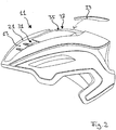
- Fig. 2
- zeigt eine Seitenansicht eines Fahrradhelms mit einem an der Außenseite zu befestigenden Schalenteil.
- Der in
Fig. 1 gezeigte Fahrradhelm 11 umfasst einen Helmkörper 13, beispielsweise aus EPS-Hartschaum, mit einer konkaven Innenseite 15 und einer konvexen Außenseite 17, sowie eine an der Außenseite 17 des Helmkörpers 13 angeordnete Außenschale 21, beispielsweise aus einem Polycarbonat. Der Fahrradhelm 11 wird auf Basis einer Inmold-Technik hergestellt und befindet sich in dem inFig. 1 gezeigten Zustand in einer Gießform 23, die eine Matrize 25 und eine Patrize 27 umfasst, welche einen Hohlraum 29 der Gießform 23 begrenzen. In der inFig. 1 gezeigten Querschnittsansicht verläuft die zeichnerische Querschnittsebene durch mehrere Belüftungsöffnungen 31 des Fahrradhelms 11, so dass sowohl der Helmkörper 13 als auch die Außenschale 21 jeweils segmentartig erscheinen. Tatsächlich bilden der Helmkörper 13 und die Außenschale 21 jedoch jeweils eine zusammenhängende Struktur. - Für die Herstellung des Fahrradhelms 11 wird zunächst die Außenschale 21 in die Matrize 25 eingelegt, so dass eine konvexe Außenseite der Außenschale 21 an einer konkaven Innenfläche der Matrize 25 anliegt. Sodann wird die Gießform 23 geschlossen. Danach wird ein Gießmaterial in die Gießform 23 eingefüllt, um den Helmkörper 13 zu bilden. Hierfür weist die Gießform 23 drei Einfüllkanäle 33 auf. Der mittlere dieser drei Einfüllkanäle 33 befindet sich in der Matrize 25 und mündet an eine Einfüllstelle 35 des Helmkörpers 13, die an der Außenseite 17 des zu bildenden Helmkörpers 13, beabstandet von dem Rand des Helmkörpers 13, angeordnet ist. Damit das Gießmaterial durch den mittleren Einfüllkanal 33 in den Hohlraum 29 der Gießform 23 gelangen kann, weist die Außenschale 21 im Bereich der Einfüllstelle 35 eine Freistellung 37 auf, d.h. der zu bildende Helmkörper 13 ist an dieser Stelle nicht von der Außenschale 21 überdeckt.
- Nach dem Einfüllen des Gießmaterials in die Gießform 23 verbindet sich dieses kraftschlüssig mit einer Innenseite der Außenschale 21. Nach einer Aushärtezeit kann die Gießform 23 geöffnet werden. Der Fahrradhelm 11 kann sodann aus der Gießform 23 entnommen und mit weiteren Ausstattungselementen versehen werden, beispielsweise einer innenseitigen Polsterung und einem Gurtfixiersystem.
- Indem die Einfüllstelle 35 des mittleren Einfüllkanals 33 an der Außenseite 17 des Helmkörpers 13 angeordnet ist, ergeben sich neuartige Möglichkeiten für die Formgebung des Helmkörpers 13, da ein homogenes Verteilen des Gießmaterials innerhalb des Hohlraums 29 der Gießform 23 einfacher bewerkstelligt werden kann. Auch der Aufbau der Gießform 23 kann hierdurch einfacher gestaltet werden.
- Aus
Fig. 2 ist ersichtlich, dass bei einem derartigen Fahrradhelm 11 eine Einfüllstelle 35 an der Außenseite 17 des Helmkörpers 13 mittels eines Schalenteils 39 überdeckt werden kann (vgl. den gestrichelt dargestellten Pfeil). Das Schalenteil 39 kann hinsichtlich Material und/oder Farbe der Außenschale 21 entsprechen. Anstelle des Schalenteils 39 kann auch ein andersartiges Abdeckteil vorgesehen sein, wie vorstehend erläutert. -
- 11
- Fahrradhelm
- 13
- Helmkörper
- 15
- Innenseite
- 17
- Außenseite
- 21
- Außenschale
- 23
- Gießform
- 25
- Matrize
- 27
- Patrize
- 29
- Hohlraum
- 31
- Belüftungsöffnung
- 33
- Einfüllkanal
- 35
- Einfüllstelle
- 37
- Freistellung
- 39
- Schalenteil
Claims (7)
- Verfahren zum Herstellen eines Schutzhelms, insbesondere eines Fahrradhelms (11), der einen stoßabsorbierenden Helmkörper (13) mit einer konkaven Innenseite (15) und einer konvexen Außenseite (17) sowie eine an der Außenseite (17) des Helmkörpers (13) angeordnete Außenschale (21) aufweist, gekennzeichnet durch die Schritte:- Einlegen der Außenschale (21) in eine Gießform (23), und- Einfüllen eines Gießmaterials in die Gießform (23) an wenigstens einer Einfüllstelle (35), um den Helmkörper (13) zu bilden, wobei das Gießmaterial sich mit einer Innenseite der Außenschale (21) verbindet,wobei die Einfüllstelle (35) an der Außenseite (17) des gebildeten Helmkörpers (13) vorgesehen ist, wobei die Außenschale (21) im Bereich der Einfüllstelle (35) eine Freistellung (37) aufweist.
- Verfahren nach Anspruch 1,
wobei die Einfüllstelle (35) von dem Rand des Helmkörpers (13) beabstandet angeordnet ist. - Verfahren nach Anspruch 1 oder 2,
wobei das Gießmaterial an mehreren Einfüllstellen (35) in die Gießform (23) eingefüllt wird, wobei wenigstens eine der mehreren Einfüllstellen (35) an der Außenseite (17) des gebildeten Helmkörpers (13) vorgesehen ist. - Verfahren nach einem der vorhergehenden Ansprüche,
wobei die Freistellung (37) der Außenschale (21) umfänglich geschlossen ist. - Verfahren nach einem der vorhergehenden Ansprüche,
wobei nach dem Entfernen des Helmkörpers (13) und der hiermit verbundenen Außenschale (21) aus der Gießform (23) die Außenseite (17) des Helmkörpers (13) im Bereich der Einfüllstelle (35) mit einem Abdeckteil, insbesondere einem Schalenteil (39), überdeckt wird. - Schutzhelm, insbesondere Fahrradhelm (11), der einen stoßabsorbierenden Helmkörper (13) sowie eine an der Außenseite (17) des Helmkörpers (13) angeordnete Außenschale (21) aufweist, dadurch gekennzeichnet dass er nach einem Verfahren gemäß einem der vorhergehenden Ansprüche hergestellt worden ist, wobei der Schutzhelm mehrere Belüftungsöffnungen (31) aufweist, die durch die Außenschale (17) und durch den Helmkörper (13) hindurch verlaufen, wobei der Helmkörper (13) an seiner Oberfläche wenigstens eine Einfüllstelle (35) für das den Helmkörper (13) bildende Gießmaterial aufweist, wobei die Einfüllstelle (35) an der Außenseite (17) des Helmkörpers (13) angeordnet ist, wobei die Einfüllstelle (35) an der Oberfläche des Helmkörpers (13) eine wahrnehmbare Störung des Erscheinungsbildes des Helmkörpers (13) bildet,
dadurch gekennzeichnet,
dass die Außenschale (21) im Bereich der Einfüllstelle (35) eine Freistellung (37) aufweist. - Schutzhelm nach Anspruch 6,
wobei die Außenseite (17) des Helmkörpers (13) im Bereich der Einfüllstelle (35) mit einem Abdeckteil, insbesondere einem Schalenteil (39), überdeckt ist.
Applications Claiming Priority (1)
| Application Number | Priority Date | Filing Date | Title |
|---|---|---|---|
| DE102017119535.1A DE102017119535A1 (de) | 2017-08-25 | 2017-08-25 | Verfahren zum Herstellen eines Schutzhelms und nach diesem Verfahren hergestellter Schutzhelm |
Publications (2)
| Publication Number | Publication Date |
|---|---|
| EP3446584A1 EP3446584A1 (de) | 2019-02-27 |
| EP3446584B1 true EP3446584B1 (de) | 2021-10-27 |
Family
ID=63079821
Family Applications (1)
| Application Number | Title | Priority Date | Filing Date |
|---|---|---|---|
| EP18186059.4A Active EP3446584B1 (de) | 2017-08-25 | 2018-07-27 | Verfahren zum herstellen eines schutzhelms und nach diesem verfahren hergestellter schutzhelm |
Country Status (5)
| Country | Link |
|---|---|
| US (1) | US20190059501A1 (de) |
| EP (1) | EP3446584B1 (de) |
| CN (1) | CN109421196B (de) |
| DE (1) | DE102017119535A1 (de) |
| PT (1) | PT3446584T (de) |
Families Citing this family (4)
| Publication number | Priority date | Publication date | Assignee | Title |
|---|---|---|---|---|
| USD902493S1 (en) * | 2018-06-18 | 2020-11-17 | Bell Sports, Inc. | Cycling helmet |
| CN115648473B (zh) * | 2022-09-26 | 2025-08-12 | 广东伯乐运动器材有限公司 | 一种衬垫层的制备方法及头盔 |
| CN115816768A (zh) * | 2022-11-18 | 2023-03-21 | 深圳美工源塑胶模具有限公司 | 一种头盔成型模具 |
| DE102024101337A1 (de) * | 2024-01-17 | 2025-07-17 | ABUS August Bremicker Söhne Kommanditgesellschaft | Helm |
Family Cites Families (16)
| Publication number | Priority date | Publication date | Assignee | Title |
|---|---|---|---|---|
| DE3222681C2 (de) * | 1982-06-16 | 1985-04-18 | Egon 4830 Gütersloh Busch | Schutzhelm und Verfahren zum Herstellen von Schutzhelmen |
| JPH089186B2 (ja) * | 1990-07-31 | 1996-01-31 | 住友ゴム工業株式会社 | 耐衝撃用具および該耐衝撃用具の製造方法 |
| CN1074854A (zh) * | 1992-01-30 | 1993-08-04 | 陈耀东 | 安全帽壳体与内层缓冲体的密贴成型制造方法 |
| DE9204816U1 (de) * | 1992-04-07 | 1992-06-11 | Callegari Promotionals AG, St. Gallen | Schutzhelm, insbesondere Sportschutzhelm |
| US5450631A (en) * | 1993-09-17 | 1995-09-19 | Specialized Bicycle Components, Inc. | Bicycle helmet |
| DE19546551C1 (de) * | 1995-12-13 | 1997-01-16 | Daimler Benz Ag | Beschichtetes Dekorteil |
| US5699561A (en) * | 1996-06-28 | 1997-12-23 | Troxel West | Self-contained bicycle helmet and molding process therefor |
| US6226801B1 (en) * | 1999-02-09 | 2001-05-08 | Adams Usa, Inc. | Football helmet having a removable inflatable liner and a method for making the same |
| CN1261058C (zh) * | 2003-09-19 | 2006-06-28 | 株式会社山清 | 安全帽、安全帽内壳层以及制造内壳层的方法 |
| CN200973399Y (zh) * | 2006-11-24 | 2007-11-14 | 林家和 | 一种改进的注射成型头盔 |
| ITTO20070936A1 (it) * | 2007-12-21 | 2009-06-22 | Cd Design S R L | Casco composito e procedimento per la sua fabbricazione |
| USD679865S1 (en) * | 2010-05-17 | 2013-04-09 | Louis Garneau Sports Inc. | Helmet |
| US9566497B2 (en) * | 2013-05-01 | 2017-02-14 | Kranos Ip Corporation | Batting helmet |
| US20150282550A1 (en) * | 2014-04-03 | 2015-10-08 | Bell Sports, Inc. | Adaptive fit helmet and method for fitting helmet to customer head |
| US9675129B2 (en) * | 2014-12-01 | 2017-06-13 | Bern Unlimited, Inc. | Helmet with vent opening control |
| US10010127B1 (en) * | 2017-06-29 | 2018-07-03 | Bell Sports, Inc. | Protective helmet with multi-density impact liners and method for same |
-
2017
- 2017-08-25 DE DE102017119535.1A patent/DE102017119535A1/de not_active Withdrawn
-
2018
- 2018-07-27 EP EP18186059.4A patent/EP3446584B1/de active Active
- 2018-07-27 PT PT181860594T patent/PT3446584T/pt unknown
- 2018-08-20 CN CN201810946682.3A patent/CN109421196B/zh active Active
- 2018-08-24 US US16/111,340 patent/US20190059501A1/en not_active Abandoned
Also Published As
| Publication number | Publication date |
|---|---|
| CN109421196B (zh) | 2021-12-03 |
| US20190059501A1 (en) | 2019-02-28 |
| EP3446584A1 (de) | 2019-02-27 |
| DE102017119535A1 (de) | 2019-02-28 |
| PT3446584T (pt) | 2021-11-30 |
| CN109421196A (zh) | 2019-03-05 |
Similar Documents
| Publication | Publication Date | Title |
|---|---|---|
| EP3446584B1 (de) | Verfahren zum herstellen eines schutzhelms und nach diesem verfahren hergestellter schutzhelm | |
| EP2113429B1 (de) | Innenverkleidung mit integrierter Airbagabdeckung | |
| DE3910889C2 (de) | ||
| DE2659935C2 (de) | Verfahren zum Herstellen von Fittings | |
| DE19929971B4 (de) | Kraftfahrzeugtür-Innenverkleidung | |
| DE112006002629T5 (de) | Helmbelüftungsstromreguliervorrichtung und -Schild | |
| DE1065302B (de) | Panzerung, insbesondere Helm, und Verfahren zu ihrer Herstellung | |
| DE602005002988T2 (de) | Integralhelm und Verfahren zu seiner Herstellung | |
| EP1731381B1 (de) | Airbageinrichtungsgrundmodul, Airbageinrichtung damit, Herstellungsverfahren und Herstellungswerkzeug für ein Airbageinrichtungsmodul | |
| DE102015109547A1 (de) | Geformte aktive Kunststoffkomponenten für eine Fahrzeugairbaganordnung | |
| DE102007023178A1 (de) | Bauteil für einen Fahrzeuginnenraum sowie eine Spritzgussanordnung und ein Verfahren zum Fertigen des Bauteils | |
| DE3936140C2 (de) | ||
| WO2009152795A1 (de) | Schutzhelm | |
| DE102014208421B4 (de) | Verfahren zur Herstellung eines Hybridbauteiles sowie ein nach diesem Verfahren hergestelltes Hybridbauteil und ein Kraftfahrzeug mit einem solchen Hybridbauteil | |
| EP2976956B1 (de) | Fahrradhelm | |
| DE102004033139B4 (de) | Kunststoffverbundformteil sowie Verfahren zu dessen Herstellung | |
| DE202010013863U1 (de) | Luftdurchlässiger Helm | |
| EP3817968B1 (de) | Fahrradsattel sowie verfahren zur herstellung eines polsterelements für einen fahrradsattel | |
| DE202007012115U1 (de) | Helm mit mehrteiliger Dekorschale | |
| DE19935389C2 (de) | Schutzhelm und Verfahren zu seiner Herstellung | |
| DE60201128T2 (de) | Verfahren zur mikrobearbeitung der oberfläche einer kunststoffform | |
| EP2829378B1 (de) | Verfahren zur Herstellung eines zusammenfaltbaren Elements | |
| DE69216859T2 (de) | Sonnenblende für kraftfahrzeug | |
| DE19504022C2 (de) | Verfahren zur Herstellung eines Sicherheitshelms als Kopfschutz gegen Schlag und Aufprall, sowie ein nach diesem Verfahren hergestellter Sicherheitshelm | |
| DE112017006277B4 (de) | Haltegriff |
Legal Events
| Date | Code | Title | Description |
|---|---|---|---|
| PUAI | Public reference made under article 153(3) epc to a published international application that has entered the european phase |
Free format text: ORIGINAL CODE: 0009012 |
|
| STAA | Information on the status of an ep patent application or granted ep patent |
Free format text: STATUS: THE APPLICATION HAS BEEN PUBLISHED |
|
| AK | Designated contracting states |
Kind code of ref document: A1 Designated state(s): AL AT BE BG CH CY CZ DE DK EE ES FI FR GB GR HR HU IE IS IT LI LT LU LV MC MK MT NL NO PL PT RO RS SE SI SK SM TR |
|
| AX | Request for extension of the european patent |
Extension state: BA ME |
|
| STAA | Information on the status of an ep patent application or granted ep patent |
Free format text: STATUS: REQUEST FOR EXAMINATION WAS MADE |
|
| 17P | Request for examination filed |
Effective date: 20190816 |
|
| RBV | Designated contracting states (corrected) |
Designated state(s): AL AT BE BG CH CY CZ DE DK EE ES FI FR GB GR HR HU IE IS IT LI LT LU LV MC MK MT NL NO PL PT RO RS SE SI SK SM TR |
|
| GRAP | Despatch of communication of intention to grant a patent |
Free format text: ORIGINAL CODE: EPIDOSNIGR1 |
|
| STAA | Information on the status of an ep patent application or granted ep patent |
Free format text: STATUS: GRANT OF PATENT IS INTENDED |
|
| INTG | Intention to grant announced |
Effective date: 20210527 |
|
| GRAS | Grant fee paid |
Free format text: ORIGINAL CODE: EPIDOSNIGR3 |
|
| GRAA | (expected) grant |
Free format text: ORIGINAL CODE: 0009210 |
|
| STAA | Information on the status of an ep patent application or granted ep patent |
Free format text: STATUS: THE PATENT HAS BEEN GRANTED |
|
| AK | Designated contracting states |
Kind code of ref document: B1 Designated state(s): AL AT BE BG CH CY CZ DE DK EE ES FI FR GB GR HR HU IE IS IT LI LT LU LV MC MK MT NL NO PL PT RO RS SE SI SK SM TR |
|
| REG | Reference to a national code |
Ref country code: GB Ref legal event code: FG4D Free format text: NOT ENGLISH |
|
| REG | Reference to a national code |
Ref country code: CH Ref legal event code: EP |
|
| REG | Reference to a national code |
Ref country code: AT Ref legal event code: REF Ref document number: 1441043 Country of ref document: AT Kind code of ref document: T Effective date: 20211115 |
|
| REG | Reference to a national code |
Ref country code: DE Ref legal event code: R096 Ref document number: 502018007562 Country of ref document: DE |
|
| REG | Reference to a national code |
Ref country code: IE Ref legal event code: FG4D Free format text: LANGUAGE OF EP DOCUMENT: GERMAN |
|
| REG | Reference to a national code |
Ref country code: PT Ref legal event code: SC4A Ref document number: 3446584 Country of ref document: PT Date of ref document: 20211130 Kind code of ref document: T Free format text: AVAILABILITY OF NATIONAL TRANSLATION Effective date: 20211124 |
|
| REG | Reference to a national code |
Ref country code: LT Ref legal event code: MG9D |
|
| REG | Reference to a national code |
Ref country code: NL Ref legal event code: MP Effective date: 20211027 |
|
| PG25 | Lapsed in a contracting state [announced via postgrant information from national office to epo] |
Ref country code: RS Free format text: LAPSE BECAUSE OF FAILURE TO SUBMIT A TRANSLATION OF THE DESCRIPTION OR TO PAY THE FEE WITHIN THE PRESCRIBED TIME-LIMIT Effective date: 20211027 Ref country code: LT Free format text: LAPSE BECAUSE OF FAILURE TO SUBMIT A TRANSLATION OF THE DESCRIPTION OR TO PAY THE FEE WITHIN THE PRESCRIBED TIME-LIMIT Effective date: 20211027 Ref country code: FI Free format text: LAPSE BECAUSE OF FAILURE TO SUBMIT A TRANSLATION OF THE DESCRIPTION OR TO PAY THE FEE WITHIN THE PRESCRIBED TIME-LIMIT Effective date: 20211027 Ref country code: BG Free format text: LAPSE BECAUSE OF FAILURE TO SUBMIT A TRANSLATION OF THE DESCRIPTION OR TO PAY THE FEE WITHIN THE PRESCRIBED TIME-LIMIT Effective date: 20220127 |
|
| PG25 | Lapsed in a contracting state [announced via postgrant information from national office to epo] |
Ref country code: IS Free format text: LAPSE BECAUSE OF FAILURE TO SUBMIT A TRANSLATION OF THE DESCRIPTION OR TO PAY THE FEE WITHIN THE PRESCRIBED TIME-LIMIT Effective date: 20220227 Ref country code: SE Free format text: LAPSE BECAUSE OF FAILURE TO SUBMIT A TRANSLATION OF THE DESCRIPTION OR TO PAY THE FEE WITHIN THE PRESCRIBED TIME-LIMIT Effective date: 20211027 Ref country code: PL Free format text: LAPSE BECAUSE OF FAILURE TO SUBMIT A TRANSLATION OF THE DESCRIPTION OR TO PAY THE FEE WITHIN THE PRESCRIBED TIME-LIMIT Effective date: 20211027 Ref country code: NO Free format text: LAPSE BECAUSE OF FAILURE TO SUBMIT A TRANSLATION OF THE DESCRIPTION OR TO PAY THE FEE WITHIN THE PRESCRIBED TIME-LIMIT Effective date: 20220127 Ref country code: NL Free format text: LAPSE BECAUSE OF FAILURE TO SUBMIT A TRANSLATION OF THE DESCRIPTION OR TO PAY THE FEE WITHIN THE PRESCRIBED TIME-LIMIT Effective date: 20211027 Ref country code: LV Free format text: LAPSE BECAUSE OF FAILURE TO SUBMIT A TRANSLATION OF THE DESCRIPTION OR TO PAY THE FEE WITHIN THE PRESCRIBED TIME-LIMIT Effective date: 20211027 Ref country code: HR Free format text: LAPSE BECAUSE OF FAILURE TO SUBMIT A TRANSLATION OF THE DESCRIPTION OR TO PAY THE FEE WITHIN THE PRESCRIBED TIME-LIMIT Effective date: 20211027 Ref country code: ES Free format text: LAPSE BECAUSE OF FAILURE TO SUBMIT A TRANSLATION OF THE DESCRIPTION OR TO PAY THE FEE WITHIN THE PRESCRIBED TIME-LIMIT Effective date: 20211027 |
|
| REG | Reference to a national code |
Ref country code: DE Ref legal event code: R097 Ref document number: 502018007562 Country of ref document: DE |
|
| PG25 | Lapsed in a contracting state [announced via postgrant information from national office to epo] |
Ref country code: SM Free format text: LAPSE BECAUSE OF FAILURE TO SUBMIT A TRANSLATION OF THE DESCRIPTION OR TO PAY THE FEE WITHIN THE PRESCRIBED TIME-LIMIT Effective date: 20211027 Ref country code: SK Free format text: LAPSE BECAUSE OF FAILURE TO SUBMIT A TRANSLATION OF THE DESCRIPTION OR TO PAY THE FEE WITHIN THE PRESCRIBED TIME-LIMIT Effective date: 20211027 Ref country code: EE Free format text: LAPSE BECAUSE OF FAILURE TO SUBMIT A TRANSLATION OF THE DESCRIPTION OR TO PAY THE FEE WITHIN THE PRESCRIBED TIME-LIMIT Effective date: 20211027 Ref country code: DK Free format text: LAPSE BECAUSE OF FAILURE TO SUBMIT A TRANSLATION OF THE DESCRIPTION OR TO PAY THE FEE WITHIN THE PRESCRIBED TIME-LIMIT Effective date: 20211027 |
|
| PLBE | No opposition filed within time limit |
Free format text: ORIGINAL CODE: 0009261 |
|
| STAA | Information on the status of an ep patent application or granted ep patent |
Free format text: STATUS: NO OPPOSITION FILED WITHIN TIME LIMIT |
|
| 26N | No opposition filed |
Effective date: 20220728 |
|
| PG25 | Lapsed in a contracting state [announced via postgrant information from national office to epo] |
Ref country code: AL Free format text: LAPSE BECAUSE OF FAILURE TO SUBMIT A TRANSLATION OF THE DESCRIPTION OR TO PAY THE FEE WITHIN THE PRESCRIBED TIME-LIMIT Effective date: 20211027 |
|
| PG25 | Lapsed in a contracting state [announced via postgrant information from national office to epo] |
Ref country code: SI Free format text: LAPSE BECAUSE OF FAILURE TO SUBMIT A TRANSLATION OF THE DESCRIPTION OR TO PAY THE FEE WITHIN THE PRESCRIBED TIME-LIMIT Effective date: 20211027 |
|
| PG25 | Lapsed in a contracting state [announced via postgrant information from national office to epo] |
Ref country code: MC Free format text: LAPSE BECAUSE OF FAILURE TO SUBMIT A TRANSLATION OF THE DESCRIPTION OR TO PAY THE FEE WITHIN THE PRESCRIBED TIME-LIMIT Effective date: 20211027 |
|
| REG | Reference to a national code |
Ref country code: CH Ref legal event code: PL |
|
| GBPC | Gb: european patent ceased through non-payment of renewal fee |
Effective date: 20220727 |
|
| REG | Reference to a national code |
Ref country code: BE Ref legal event code: MM Effective date: 20220731 |
|
| PG25 | Lapsed in a contracting state [announced via postgrant information from national office to epo] |
Ref country code: LU Free format text: LAPSE BECAUSE OF NON-PAYMENT OF DUE FEES Effective date: 20220727 Ref country code: LI Free format text: LAPSE BECAUSE OF NON-PAYMENT OF DUE FEES Effective date: 20220731 Ref country code: CH Free format text: LAPSE BECAUSE OF NON-PAYMENT OF DUE FEES Effective date: 20220731 |
|
| PG25 | Lapsed in a contracting state [announced via postgrant information from national office to epo] |
Ref country code: GB Free format text: LAPSE BECAUSE OF NON-PAYMENT OF DUE FEES Effective date: 20220727 Ref country code: BE Free format text: LAPSE BECAUSE OF NON-PAYMENT OF DUE FEES Effective date: 20220731 |
|
| PG25 | Lapsed in a contracting state [announced via postgrant information from national office to epo] |
Ref country code: IE Free format text: LAPSE BECAUSE OF NON-PAYMENT OF DUE FEES Effective date: 20220727 |
|
| PG25 | Lapsed in a contracting state [announced via postgrant information from national office to epo] |
Ref country code: HU Free format text: LAPSE BECAUSE OF FAILURE TO SUBMIT A TRANSLATION OF THE DESCRIPTION OR TO PAY THE FEE WITHIN THE PRESCRIBED TIME-LIMIT; INVALID AB INITIO Effective date: 20180727 |
|
| PG25 | Lapsed in a contracting state [announced via postgrant information from national office to epo] |
Ref country code: MK Free format text: LAPSE BECAUSE OF FAILURE TO SUBMIT A TRANSLATION OF THE DESCRIPTION OR TO PAY THE FEE WITHIN THE PRESCRIBED TIME-LIMIT Effective date: 20211027 Ref country code: CY Free format text: LAPSE BECAUSE OF FAILURE TO SUBMIT A TRANSLATION OF THE DESCRIPTION OR TO PAY THE FEE WITHIN THE PRESCRIBED TIME-LIMIT Effective date: 20211027 |
|
| PG25 | Lapsed in a contracting state [announced via postgrant information from national office to epo] |
Ref country code: TR Free format text: LAPSE BECAUSE OF FAILURE TO SUBMIT A TRANSLATION OF THE DESCRIPTION OR TO PAY THE FEE WITHIN THE PRESCRIBED TIME-LIMIT Effective date: 20211027 |
|
| REG | Reference to a national code |
Ref country code: AT Ref legal event code: MM01 Ref document number: 1441043 Country of ref document: AT Kind code of ref document: T Effective date: 20230727 |
|
| PG25 | Lapsed in a contracting state [announced via postgrant information from national office to epo] |
Ref country code: MT Free format text: LAPSE BECAUSE OF FAILURE TO SUBMIT A TRANSLATION OF THE DESCRIPTION OR TO PAY THE FEE WITHIN THE PRESCRIBED TIME-LIMIT Effective date: 20211027 |
|
| PG25 | Lapsed in a contracting state [announced via postgrant information from national office to epo] |
Ref country code: AT Free format text: LAPSE BECAUSE OF NON-PAYMENT OF DUE FEES Effective date: 20230727 |
|
| PG25 | Lapsed in a contracting state [announced via postgrant information from national office to epo] |
Ref country code: AT Free format text: LAPSE BECAUSE OF NON-PAYMENT OF DUE FEES Effective date: 20230727 |
|
| PG25 | Lapsed in a contracting state [announced via postgrant information from national office to epo] |
Ref country code: GR Free format text: LAPSE BECAUSE OF NON-PAYMENT OF DUE FEES Effective date: 20211027 |
|
| PG25 | Lapsed in a contracting state [announced via postgrant information from national office to epo] |
Ref country code: GR Free format text: LAPSE BECAUSE OF NON-PAYMENT OF DUE FEES Effective date: 20211027 |
|
| PGFP | Annual fee paid to national office [announced via postgrant information from national office to epo] |
Ref country code: PT Payment date: 20250717 Year of fee payment: 8 |
|
| PGFP | Annual fee paid to national office [announced via postgrant information from national office to epo] |
Ref country code: IT Payment date: 20250724 Year of fee payment: 8 |
|
| PGFP | Annual fee paid to national office [announced via postgrant information from national office to epo] |
Ref country code: FR Payment date: 20250725 Year of fee payment: 8 |
|
| PGFP | Annual fee paid to national office [announced via postgrant information from national office to epo] |
Ref country code: CZ Payment date: 20250718 Year of fee payment: 8 |
|
| PGFP | Annual fee paid to national office [announced via postgrant information from national office to epo] |
Ref country code: RO Payment date: 20250722 Year of fee payment: 8 |
|
| PGFP | Annual fee paid to national office [announced via postgrant information from national office to epo] |
Ref country code: DE Payment date: 20250926 Year of fee payment: 8 |
|
| PGFP | Annual fee paid to national office [announced via postgrant information from national office to epo] |
Ref country code: AT Payment date: 20260410 Year of fee payment: 5 |