EP3446837B1 - Dispositif de commande de robot, système de robot, procédé de commande de robot et programme de commande de robot - Google Patents
Dispositif de commande de robot, système de robot, procédé de commande de robot et programme de commande de robot Download PDFInfo
- Publication number
- EP3446837B1 EP3446837B1 EP18155643.2A EP18155643A EP3446837B1 EP 3446837 B1 EP3446837 B1 EP 3446837B1 EP 18155643 A EP18155643 A EP 18155643A EP 3446837 B1 EP3446837 B1 EP 3446837B1
- Authority
- EP
- European Patent Office
- Prior art keywords
- robot
- distance
- stopped
- robot arm
- relative
- Prior art date
- Legal status (The legal status is an assumption and is not a legal conclusion. Google has not performed a legal analysis and makes no representation as to the accuracy of the status listed.)
- Active
Links
Images


Classifications
-
- B—PERFORMING OPERATIONS; TRANSPORTING
- B25—HAND TOOLS; PORTABLE POWER-DRIVEN TOOLS; MANIPULATORS
- B25J—MANIPULATORS; CHAMBERS PROVIDED WITH MANIPULATION DEVICES
- B25J9/00—Program-controlled manipulators
- B25J9/16—Program controls
- B25J9/1656—Program controls characterised by programming, planning systems for manipulators
- B25J9/1664—Program controls characterised by programming, planning systems for manipulators characterised by motion, path, trajectory planning
- B25J9/1666—Avoiding collision or forbidden zones
-
- B—PERFORMING OPERATIONS; TRANSPORTING
- B25—HAND TOOLS; PORTABLE POWER-DRIVEN TOOLS; MANIPULATORS
- B25J—MANIPULATORS; CHAMBERS PROVIDED WITH MANIPULATION DEVICES
- B25J9/00—Program-controlled manipulators
- B25J9/16—Program controls
- B25J9/1674—Program controls characterised by safety, monitoring, diagnostic
- B25J9/1676—Avoiding collision or forbidden zones
-
- B—PERFORMING OPERATIONS; TRANSPORTING
- B25—HAND TOOLS; PORTABLE POWER-DRIVEN TOOLS; MANIPULATORS
- B25J—MANIPULATORS; CHAMBERS PROVIDED WITH MANIPULATION DEVICES
- B25J9/00—Program-controlled manipulators
- B25J9/16—Program controls
- B25J9/1628—Program controls characterised by the control loop
- B25J9/1651—Program controls characterised by the control loop acceleration, rate control
-
- B—PERFORMING OPERATIONS; TRANSPORTING
- B25—HAND TOOLS; PORTABLE POWER-DRIVEN TOOLS; MANIPULATORS
- B25J—MANIPULATORS; CHAMBERS PROVIDED WITH MANIPULATION DEVICES
- B25J9/00—Program-controlled manipulators
- B25J9/16—Program controls
- B25J9/1694—Program controls characterised by use of sensors other than normal servo-feedback from position, speed or acceleration sensors, perception control, multi-sensor controlled systems, sensor fusion
-
- B—PERFORMING OPERATIONS; TRANSPORTING
- B25—HAND TOOLS; PORTABLE POWER-DRIVEN TOOLS; MANIPULATORS
- B25J—MANIPULATORS; CHAMBERS PROVIDED WITH MANIPULATION DEVICES
- B25J9/00—Program-controlled manipulators
- B25J9/16—Program controls
- B25J9/1694—Program controls characterised by use of sensors other than normal servo-feedback from position, speed or acceleration sensors, perception control, multi-sensor controlled systems, sensor fusion
- B25J9/1697—Vision controlled systems
-
- G—PHYSICS
- G05—CONTROLLING; REGULATING
- G05B—CONTROL OR REGULATING SYSTEMS IN GENERAL; FUNCTIONAL ELEMENTS OF SUCH SYSTEMS; MONITORING OR TESTING ARRANGEMENTS FOR SUCH SYSTEMS OR ELEMENTS
- G05B2219/00—Program-control systems
- G05B2219/30—Nc systems
- G05B2219/39—Robotics, robotics to robotics hand
- G05B2219/39091—Avoid collision with moving obstacles
-
- G—PHYSICS
- G05—CONTROLLING; REGULATING
- G05B—CONTROL OR REGULATING SYSTEMS IN GENERAL; FUNCTIONAL ELEMENTS OF SUCH SYSTEMS; MONITORING OR TESTING ARRANGEMENTS FOR SUCH SYSTEMS OR ELEMENTS
- G05B2219/00—Program-control systems
- G05B2219/30—Nc systems
- G05B2219/39—Robotics, robotics to robotics hand
- G05B2219/39097—Estimate own stop, brake time, then verify if in safe distance
-
- G—PHYSICS
- G05—CONTROLLING; REGULATING
- G05B—CONTROL OR REGULATING SYSTEMS IN GENERAL; FUNCTIONAL ELEMENTS OF SUCH SYSTEMS; MONITORING OR TESTING ARRANGEMENTS FOR SUCH SYSTEMS OR ELEMENTS
- G05B2219/00—Program-control systems
- G05B2219/30—Nc systems
- G05B2219/39—Robotics, robotics to robotics hand
- G05B2219/39098—Estimate stop, brake distance in predef time, then verify if in safe distance
-
- Y—GENERAL TAGGING OF NEW TECHNOLOGICAL DEVELOPMENTS; GENERAL TAGGING OF CROSS-SECTIONAL TECHNOLOGIES SPANNING OVER SEVERAL SECTIONS OF THE IPC; TECHNICAL SUBJECTS COVERED BY FORMER USPC CROSS-REFERENCE ART COLLECTIONS [XRACs] AND DIGESTS
- Y10—TECHNICAL SUBJECTS COVERED BY FORMER USPC
- Y10S—TECHNICAL SUBJECTS COVERED BY FORMER USPC CROSS-REFERENCE ART COLLECTIONS [XRACs] AND DIGESTS
- Y10S901/00—Robots
- Y10S901/02—Arm motion controller
- Y10S901/09—Closed loop, sensor feedback controls arm movement
-
- Y—GENERAL TAGGING OF NEW TECHNOLOGICAL DEVELOPMENTS; GENERAL TAGGING OF CROSS-SECTIONAL TECHNOLOGIES SPANNING OVER SEVERAL SECTIONS OF THE IPC; TECHNICAL SUBJECTS COVERED BY FORMER USPC CROSS-REFERENCE ART COLLECTIONS [XRACs] AND DIGESTS
- Y10—TECHNICAL SUBJECTS COVERED BY FORMER USPC
- Y10S—TECHNICAL SUBJECTS COVERED BY FORMER USPC CROSS-REFERENCE ART COLLECTIONS [XRACs] AND DIGESTS
- Y10S901/00—Robots
- Y10S901/46—Sensing device
-
- Y—GENERAL TAGGING OF NEW TECHNOLOGICAL DEVELOPMENTS; GENERAL TAGGING OF CROSS-SECTIONAL TECHNOLOGIES SPANNING OVER SEVERAL SECTIONS OF THE IPC; TECHNICAL SUBJECTS COVERED BY FORMER USPC CROSS-REFERENCE ART COLLECTIONS [XRACs] AND DIGESTS
- Y10—TECHNICAL SUBJECTS COVERED BY FORMER USPC
- Y10S—TECHNICAL SUBJECTS COVERED BY FORMER USPC CROSS-REFERENCE ART COLLECTIONS [XRACs] AND DIGESTS
- Y10S901/00—Robots
- Y10S901/46—Sensing device
- Y10S901/47—Optical
Definitions
- the present invention relates to a technology for realizing cooperative work between a robot and a moving body.
- JP 4648486 B deceleration of a speed at which a robot can move according to a condition considering a distance between a worker and the robot, and provision of a robot entry prohibition region for performing control of not allowing the robot to enter was investigated.
- JP 5370127 B control for performing deceleration and emergency stop of a robot using a distance between the robot and a worker was investigated.
- an analysis module may detect that an unintended object is approaching the robotic equipment, and based on a proximity and/or a speed of approach of the object to the robotic equipment, the analysis module may instruct the robotic equipment to reduce an operating speed and/or stop motion of the robotic equipment.
- SSM speed and separation monitoring
- the robot control device of the present invention is provided as set forth in claim 1. Moreover, according to other aspects of the present invention, a robot system as set forth in claim 6, a method of controlling a robot as set forth in claim 7, and a corresponding program as set forth in claim 8 are provided. Preferred embodiments of the present invention may be gathered from the dependent claims.
- a robot arm which is able to move about a support point, a detection unit which detects a relative positional relationship with a moving body, a control unit which generates a drive control signal of an actuator which causes the robot arm to be able to move on the basis of a change in the relative positional relationship between the robot arm and the moving body detected by the detection unit, and an output unit which outputs the drive control signal generated by the control unit to the actuator are provided.
- the detection unit detects the relative positional relationship between the robot arm and the moving body by a sensor attached to the robot arm.
- the control unit generates the drive control signal which changes a speed at which the robot arm is able to move in accordance with a change in the relative positional relationship with the moving body.
- the output unit outputs the drive control signal to the actuator.
- the robot arm may include the support point formed on one end portion thereof and the sensor attached to the other end portion thereof. With such a configuration, the robot arm can detect a relative position of the moving body at a position at which a distance to the moving body is furthest, that is, a position at which the robot arm and the moving body are most likely to collide, and thus it is possible to reduce the number of sensors.
- the control unit may generate the drive control signal using a relative speed between the robot arm and the moving body calculated from a change in the relative positional relationship between the robot arm and the moving body.
- the control unit may generate the drive control signal using a relative distance between the robot arm and the moving body calculated from a change in the relative speed between the robot arm and the moving body. With such a configuration, it is possible to generate a drive control signal by acquiring the relative distance due to a change in the relative speed between the robot arm and the moving body. Further, it is possible to calculate the relative speed from the relative distance.
- the control unit may generate the drive control signal for stopping the robot arm when the relative distance between the robot arm and the moving body is shorter than a predetermined stopped distance.
- the control unit may generate the drive control signal for decelerating or accelerating the robot arm when the relative distance between the robot arm and the moving body is longer than a predetermined stopped distance.
- the present invention it is possible to secure safety of the moving body when the robot is able to move without increasing the distance between the robot and the moving body.
- FIG. 1 is a schematic view illustrating a relationship between a robot 1, a worker 2, and a controller 3 using a robot control device according to this example.
- the robot 1 of this example includes a plurality of robot aims 11, support points (joints) 12, 12A, and 12B, and a robot hand 10.
- a sensor 15 is provided in the robot hand 10.
- the robot 1 is fixed to a robot base 20 by the support point 12.
- the robot base 20 may have a turning structure.
- the support points 12, 12A and 12B can be moved as joints of the robot 1.
- the robot 1 includes an actuator as a drive mechanism for moving these joints.
- a distance between the robot and a moving body in the present invention refers to a distance between a position of the robot hand 10 farthest from a base point of the robot base 20 and the moving body. In other words, this is a distance between an end of a maximum range of the robot at that time and the moving body.
- a range in which the robot can move varies depending on the number of joints (number of axes).
- the sensor 15 of the robot 1 detects a relative positional relationship with the worker 2.
- the worker 2 is a moving body in the present invention.
- the controller 3 is a control unit of the present invention.
- the sensor 15 is formed as, for example, a displacement sensor, an ultrasonic sensor, a millimeter wave sensor, an optical sensor, or the like.
- a relative position detected by the sensor 15 is three-dimensional if the robot hand 10 (robot arm 11) can move in three dimensions. Further, the relative position detected by the sensor 15 is two-dimensional if the robot hand 10 (robot arm 11) can move in two dimensions.
- the sensor 15 continuously detects the relative position at predetermined time intervals. It is assumed that the worker 2 moves in a worker movement direction, and similarly, the robot hand 10 moves in a robot arm movement direction.
- the sensor 15 calculates a relative speed between the worker 2 and the robot hand 10.
- the sensor 15 transmits the calculated relative speed as sensing data to the controller 3.
- the controller 3 generates a drive control signal based on a predetermined risk determination of the sensing data.
- the controller 3 transmits the drive control signal to the robot 1.
- the robot 1 transmits the drive control signal to actuators provided in the support points 12, 12A and 12B.
- the risk determination refers to a prescribed value determined so that the robot 1 and the worker 2 are capable of moving safely without collision.
- a sensing unit 15A, a detection unit 15B, and a controller connection unit 15C are provided in the sensor 15.
- a sensing device connection unit 3A, a control unit 3B, and an output unit 3C are provided in the controller 3.
- a separation distance estimating function unit 31B and a risk determination function unit 32B are provided in the control unit 3B. It is assumed that the sensor 15 is attached to the robot hand 10 (a distal end of the robot arm 11) of the robot 1. Also, the sensor 15 is assumed to be, for example, a displacement sensor and will be described below.
- the sensing unit 15A is a sensing element and outputs a sensor signal corresponding to the positional relationship between the sensor 15 including the sensing unit 15A itself and the worker 2 to the detection unit 15B.
- the detection unit 15B calculates the relative positional relationship of the sensor 15 with respect to the worker 2 using the sensor signal.
- the detection unit 15B outputs the relative positional relationship to the controller connection unit 15C.
- the controller connection unit 15C transmits the relative positional relationship to the sensing device connection unit 3A.
- the sensing device connection unit 3A receives the relative positional relationship from the controller connection unit 15C.
- the sensing device connection unit 3A transmits the relative positional relationship to the separation distance estimating function unit 31B.
- the separation distance estimating function unit 31B calculates a relative speed of the sensor 15 and the worker 2 from a temporal change of the relative positional relationship. Also, a stopped relative distance when an emergency stop occurs is calculated from the relative positional relationship.
- the separation distance estimating function unit 31B transmits the stopped relative distance and the relative speed to the risk determination function unit 32B.
- the risk determination function unit 32B transmits the drive control signal generated by the predetermined risk determination to the output unit 3C on the basis of the stopped relative distance and the relative speed.
- the output unit 3C transmits the drive control signal to the actuator of the robot 1.
- the separation distance estimating function unit 31B can calculate a relative positional relationship by integrating the relative speeds.
- FIG. 3 is a view for specifically describing a method of estimating a stopped relative distance at the time of an emergency stop using the separation distance estimating function unit 31B.
- a case in which a two-dimensional relative speed is used is taken as an example.
- the robot hand 10 may move along a trajectory of a point RA1, a point RA2, and a point RA3 toward the worker 2 (in a robot traveling direction).
- a trajectory of the robot hand 10 at the time of emergency stop will be described.
- the worker 2 moves along a trajectory of a point SA1, a point SA2, and a point SA3 toward the robot 1 (in a worker traveling direction).
- the points RA1 and SA1, the points RA2 and SA2, and the points RA3 and SA3 indicate respective positions of the robot 1 and the worker 2 at the same time.
- the stopped relative distance refers to a relative distance between the robot hand 10 (robot 1) and the worker 2 at the time when the robot hand 10 is assumed to have been stopped.
- the robot 1 moves at a speed vr1 at the point RA1, a speed vr2 at the point RA2, and a speed vr3 at the point RA3.
- the worker 2 moves at a speed vs1 at the point SA1, the speed vs2 at the point SA2, and the speed vs3 at the point SA3.
- the speed vs1, the speed vs2, and the speed vs3 are variable, but may also be constant.
- the controller 3 calculates the stopped relative distance with the worker 2. Further, it is assumed that the robot hand 10 stops at the point RA3.
- the robot hand 10 does not stop at the point RA2 due to inertia of the robot hand 10 and decelerates from the speed vr1. For example, it decelerates from the speed vr1 and further decelerates via the speed vr2.
- the robot hand 10 has a speed lower than the speed vr2, that is, the speed vr3 at which the speed is 0, and stops.
- a distance calculated from a position of the robot hand 10 at the point RA3 and a position of the worker 2 at the point SA3 is the stopped relative distance.
- the sensor 15 acquires a relative distance with the worker 2 (S1). Also, the sensor 15 acquires a relative speed with the worker 2.
- the controller 3 estimates a relative distance at the time of emergency stop (S2).
- the relative distance at the time of emergency stop is a distance between the robot hand 10 and the worker 2 when the robot hand 10 is stopped in a case in which an emergency stop is performed at a current relative distance and current relative speed. That is, when the robot 1 and the worker 2 move forward to a certain point, it is a distance calculated by estimating a case in which an emergency stop is performed at an arbitrary point of time. This is the stopped relative distance.
- a relative distance and a relative speed of the distal end of the robot 1, that is, the sensor 15 attached to the robot hand 10 and the worker 2 are calculated.
- a distance between the robot hand 10 and the worker 2 when the robot hand 10 is stopped is calculated assuming that the robot hand 10 decelerates while the worker 2 does not decelerate.
- the controller 3 determines whether or not the stopped relative distance is smaller than a predetermined stopped distance PD (S4).
- the positive value in the stopped relative distance means that there is a distance in which the robot hand 10 does not collide with the worker 2 when an emergency stop is made at the present point of time.
- the controller 3 decelerates the robot hand 10 while maintaining its moving direction (S5) with respect to the robot 1. That is, the robot hand 10 decelerates while maintaining the trajectory of the robot hand 10.
- the stopped relative distance smaller than the stopped distance PD means that the robot hand 10 and the worker 2 come close to each other when the robot 1 and the worker 2 move while maintaining the relative speed.
- the deceleration speed is set to satisfy a condition in which the stopped relative distance > PD.
- the controller 3 acquires another relative position and relative speed, and determines whether or not the stopped relative distance is smaller than the stopped distance PD (S6). When the stopped relative distance is smaller than the stopped distance PD (S6: Yes), the robot is emergently stopped (S7).
- the robot accelerates to a speed at which it can be accelerated or moves at a constant speed (S11), and another relative speed is acquired (S1).
- the robot 1 and the worker 2 can perform a safe cooperative work without collision. Further, a distance at which a movable portion of the robot and the moving body can be prevented from colliding can be made smaller than a conventional configuration.
- the sensor 15 acquires a relative speed
- the relative speed described above is specifically calculated as follows. In the following description, a case using a two-dimensional relative speed is taken as an example.
- the robot in FIGS. 5A and 5B is, for example, a vertical articulated robot.
- FIG. 5A is a schematic side view of the robot 1 and the worker 2.
- FIG. 5B is a schematic view of the robot 1 and the worker 2 viewed from a top.
- Vt a relative speed vector detected by the sensor 15 when the robot hand 10 is moved in a traveling direction toward the worker 2 is defined as Vt.
- An axis connecting the robot base 20 (support point 12) to which the robot 1 is fixed and the worker 2 in a straight line is defined as an X axis.
- An axis perpendicular to the X axis is defined as a Y axis.
- An angle between the relative speed vector Vt and the X axis is defined as ⁇ 1.
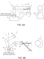
- FIGS. 6A and 6B an overview of calculating a relative speed of the robot and the worker (person) when the robot is able to move will be described.
- the robot in FIGS. 6A and 6B is, for example, a horizontal articulated robot.
- FIG. 6A is a schematic side view of the robot 1 and the worker 2.
- FIG. 6B is a schematic view of the robot 1 and the worker 2 viewed from a top.
- Vt2 a relative speed vector detected by the sensor 15 when the robot hand 10 is rotated in a rotating direction toward the worker 2 is defined as Vt2.
- An axis connecting the robot base 20 (support point 12) to which the robot 1 is fixed and the worker 2 in a straight line is defined as an X axis.
- An axis perpendicular to the X axis is defined as a Y axis.
- An angle between the relative speed vector Vt2 and the X axis is defined as ⁇ 2.
- the method of calculating the stopped relative distance and the relative speed in the control unit has been described.
- the relative distance and the relative speed may be calculated by a detection unit.
- the relative speed between the robot and the worker is acquired by attaching a sensor to the distal end of the robot (the robot hand in the above example).
- a sensor is attached to each of the support points (joints) of the robot.
- the relative speed or the relative distance is sensed by each sensor of the support points (joints)
- more detailed sensing data can be obtained, and thereby safety can be improved further.
Landscapes
- Engineering & Computer Science (AREA)
- Robotics (AREA)
- Mechanical Engineering (AREA)
- Manipulator (AREA)
Claims (8)
- Dispositif de commande de robot pour commander un robot (1), le robot (1) comprenant un bras de robot (11) adapté pour se déplacer autour d'un point de support (12, 12A, 12B), dans lequel le bras de robot (11) comprend une main de robot (10) située à une extrémité distale du bras de robot (11) ;dans lequel le dispositif de commande de robot comprend :une unité de détection (15B) adaptée pour détecter une relation de position relative avec un corps mobile (2) ;une unité de commande (3B) adaptée pour générer un signal de commande d'entraînement d'un actionneur qui provoque un déplacement du bras de robot (11) sur la base d'un changement de la relation de position relative entre le bras de robot (11) et le corps mobile (2) détectée par l'unité de détection (15B) ; etune unité de sortie (3C) adaptée pour envoyer le signal de commande d'entraînement généré par l'unité de commande (3B) à l'actionneur,dans lequel l'unité de détection (15B) détecte la relation de position relative entre le bras de robot (11) et le corps mobile (2) à l'aide d'un capteur (15) attaché au bras de robot (11),caractérisé en ce quel'unité de commande (3B) est en outre adaptée pour estimer (S2) une distance relative à l'arrêt lors d'un arrêt d'urgence, dans lequel la distance relative à l'arrêt est une distance entre la main de robot (10) et le corps mobile (2) quand la main de robot (10) est arrêtée en effectuant l'arrêt d'urgence ;l'unité de commande (3B) est en outre adaptée pour accélérer (S11) la main de robot (10) quand (S4) la distance relative à l'arrêt est supérieure à une distance à l'arrêt prédéterminée (PD), etquand (S4) la distance relative à l'arrêt est inférieure à la distance à l'arrêt prédéterminée (PD), l'unité de commande (3B) est en outre adaptée pour :décélérer (S5) la main de robot (10) tout en maintenant sa direction de déplacement par rapport au robot (1) ; déterminer ultérieurement (S6) si la distance relative à l'arrêt est ou non inférieure à la distance à l'arrêt prédéterminée (PD), etarrêter d'urgence (S7) la main de robot (10) quand (S6) la distance relative à l'arrêt déterminée ultérieurement est inférieure à la distance à l'arrêt prédéterminée (PD).
- Dispositif de commande de robot selon la revendication 1, dans lequel le bras de robot (11) comprend le point de support (12, 12A, 12B) formé sur un côté de portion d'extrémité de celui-ci et le capteur (15) attaché à l'autre côté de portion d'extrémité de celui-ci.
- Dispositif de commande de robot selon la revendication 1 ou 2, dans lequel l'unité de commande (3B) est adaptée pour générer le signal de commande d'entraînement en utilisant une vitesse relative entre le bras de robot (11) et le corps mobile (2) calculée à partir d'un changement de la relation de position relative entre le bras de robot (11) et le corps mobile (2).
- Dispositif de commande de robot selon l'une quelconque des revendications 1 à 3, dans lequel l'unité de commande (3B) est adaptée pour générer le signal de commande d'entraînement en utilisant une distance relative entre le bras de robot (11) et le corps mobile (2) calculée à partir d'un changement de la vitesse relative entre le bras de robot (11) et le corps mobile (2) .
- Dispositif de commande de robot selon l'une quelconque des revendications 1 à 4, dans lequel l'unité de commande (3B) est adaptée pour générer le signal de commande d'entraînement pour arrêter le bras de robot (11) quand la distance relative entre le bras de robot (11) et le corps mobile (2) est inférieure à la distance à l'arrêt prédéterminée (PD).
- Système de robot, comprenant :un robot (1) comportant un bras de robot (11) adapté pour se déplacer autour d'un point de support (12, 12A, 12B), dans lequel le bras de robot (11) comporte une main de robot (10) située à une extrémité distale du bras de robot (11) ; etun dispositif de commande de robot selon l'une quelconque des revendications 1 à 5.
- Procédé de commande d'un robot (1) exécuté par un ordinateur, dans lequel le robot (1) comprend un bras de robot (11) adapté pour se déplacer autour d'un point de support (12, 12A, 12B), dans lequel le bras de robot (11) comprend une main de robot (10) située à une extrémité distale du bras de robot (11),le procédé comprenant :une étape de détection consistant à détecter une relation de position relative entre le bras de robot (11) et un corps mobile (2) à partir d'une sortie de détection d'un capteur (15) attaché au bras de robot (11) ;une étape de génération consistant à générer un signal de commande d'entraînement d'un actionneur qui provoque un déplacement du bras de robot (11) sur la base d'un changement de la relation de position relative détectée entre le bras de robot (11) et le corps mobile (2) ; etune étape de sortie consistant à envoyer le signal de commande d'entraînement à l'actionneur,caractérisé par :
une étape d'estimation (S2) d'une distance relative à l'arrêt lors d'un arrêt d'urgence, dans lequel la distance relative à l'arrêt est une distance entre la main de robot (10) et le corps mobile quand la main de robot (10) est arrêtée en effectuant l'arrêt d'urgence, une étape d'accélération (S11) de la main de robot (10) quand (S4) la distance relative à l'arrêt est supérieure à une distance à l'arrêt prédéterminée (PD),et caractérisé en outre en ce que :
quand (S4) la distance relative à l'arrêt est inférieure à la distance à l'arrêt prédéterminée (PD), le procédé comprend en outre :une étape de décélération (S5) de la main de robot (10) ;une étape de détermination ultérieure (S6) du fait que la distance relative à l'arrêt est inférieure ou non à la distance à l'arrêt prédéterminée (PD) ; etune étape d'arrêt d'urgence (S7) de la main de robot (10) quand (S6) la distance relative à l'arrêt déterminée ultérieurement est inférieure à la distance à l'arrêt prédéterminée (PD). - Programme comprenant des instructions qui, lorsqu'elles sont exécutées par un ordinateur, sont adaptées pour mettre en œuvre le procédé selon la revendication 7.
Applications Claiming Priority (1)
| Application Number | Priority Date | Filing Date | Title |
|---|---|---|---|
| JP2017161770A JP7329902B2 (ja) | 2017-08-25 | 2017-08-25 | ロボット制御装置、ロボットシステム、ロボット制御方法、および、ロボット制御プログラム |
Publications (2)
| Publication Number | Publication Date |
|---|---|
| EP3446837A1 EP3446837A1 (fr) | 2019-02-27 |
| EP3446837B1 true EP3446837B1 (fr) | 2023-06-07 |
Family
ID=61187231
Family Applications (1)
| Application Number | Title | Priority Date | Filing Date |
|---|---|---|---|
| EP18155643.2A Active EP3446837B1 (fr) | 2017-08-25 | 2018-02-07 | Dispositif de commande de robot, système de robot, procédé de commande de robot et programme de commande de robot |
Country Status (4)
| Country | Link |
|---|---|
| US (1) | US20190061155A1 (fr) |
| EP (1) | EP3446837B1 (fr) |
| JP (2) | JP7329902B2 (fr) |
| CN (1) | CN109421046A (fr) |
Families Citing this family (15)
| Publication number | Priority date | Publication date | Assignee | Title |
|---|---|---|---|---|
| JP7329902B2 (ja) * | 2017-08-25 | 2023-08-21 | オムロン株式会社 | ロボット制御装置、ロボットシステム、ロボット制御方法、および、ロボット制御プログラム |
| JP7058126B2 (ja) * | 2018-01-12 | 2022-04-21 | 株式会社日立製作所 | ロボット制御装置および自動組立システム |
| JP6687654B2 (ja) * | 2018-03-14 | 2020-04-28 | ファナック株式会社 | 協働ロボットの制御装置及び制御方法 |
| JP7141232B2 (ja) * | 2018-04-06 | 2022-09-22 | 川崎重工業株式会社 | ロボットの制御装置 |
| JP7036078B2 (ja) * | 2019-03-28 | 2022-03-15 | オムロン株式会社 | 制御システム、制御方法、および制御ユニット |
| JP7294880B2 (ja) * | 2019-05-20 | 2023-06-20 | ファナック株式会社 | ロボット制御装置、ロボットシステム、及びロボット制御方法 |
| US11123870B2 (en) * | 2019-09-27 | 2021-09-21 | HighRes Biosolutions, Inc. | Robotic transport system and method therefor |
| JP7707478B2 (ja) * | 2020-05-12 | 2025-07-15 | ソレマルテック エス.エー. | 作業デバイス |
| JP7482719B2 (ja) * | 2020-08-27 | 2024-05-14 | 京セラ株式会社 | ロボット制御装置、ロボット制御システム、及びロボット制御方法 |
| CN114683273B (zh) * | 2020-12-31 | 2024-05-24 | 美的集团(上海)有限公司 | 机器人停机控制方法、装置、机器人及存储介质 |
| CN113319891A (zh) * | 2021-01-28 | 2021-08-31 | 山东硅步机器人技术有限公司 | 一种低延迟机器人检测机械臂碰撞的方法 |
| WO2023053053A1 (fr) * | 2021-09-29 | 2023-04-06 | Gaiotto Automation S.P.A. | Procédé de contrôle de sécurité, lors de l'apprentissage direct, d'un système robotisé et système robotisé associé |
| US12552034B2 (en) * | 2021-12-25 | 2026-02-17 | Mantis Robotics, Inc. | Robot system |
| US12409550B2 (en) * | 2022-01-12 | 2025-09-09 | Mantis Robotics, Inc. | Robot system with casing elements |
| US12459123B2 (en) | 2022-02-16 | 2025-11-04 | Mantis Robotics, Inc. | Robot system with object detecting sensors |
Citations (1)
| Publication number | Priority date | Publication date | Assignee | Title |
|---|---|---|---|---|
| DE10361132A1 (de) * | 2003-06-18 | 2005-01-27 | Elan Schaltelemente Gmbh & Co. Kg | Verfahren zur Überwachung der Bewegung eines sich in mehreren Freiheitsgraden bewegenden Gefahr bringenden Objektes wie Handhabungsmasse und/oder der beweglichen Masse eines Handhabungsgerätes |
Family Cites Families (17)
| Publication number | Priority date | Publication date | Assignee | Title |
|---|---|---|---|---|
| JPH11188687A (ja) * | 1997-12-26 | 1999-07-13 | Mitsubishi Electric Corp | 制御装置 |
| JP2003215238A (ja) * | 2002-01-23 | 2003-07-30 | Mitsubishi Heavy Ind Ltd | 近接信管装置 |
| JP4127043B2 (ja) * | 2002-12-11 | 2008-07-30 | ソニー株式会社 | 脚式移動ロボット並びに脚式移動ロボットの関節軸として適用されるアクチュエータ装置 |
| JP2005288657A (ja) * | 2004-04-05 | 2005-10-20 | Matsushita Electric Ind Co Ltd | ロボット |
| ATE504869T1 (de) * | 2006-09-30 | 2011-04-15 | Abb Technology Ag | Verfahren und system zur auslegung und überprüfung von sicherheitsbereichen eines roboters |
| JP2009090403A (ja) * | 2007-10-05 | 2009-04-30 | Fanuc Ltd | ロボット動作範囲設定装置 |
| JP5365524B2 (ja) * | 2007-12-07 | 2013-12-11 | 株式会社安川電機 | ロボット動作規制方法およびロボットシステム |
| JP4648486B2 (ja) | 2009-01-26 | 2011-03-09 | ファナック株式会社 | 人間とロボットとの協調動作領域を有する生産システム |
| JP5370127B2 (ja) * | 2009-12-18 | 2013-12-18 | 株式会社デンソーウェーブ | ロボットの干渉回避装置 |
| JP5523386B2 (ja) * | 2011-04-15 | 2014-06-18 | 三菱電機株式会社 | 衝突回避装置 |
| JP5668770B2 (ja) * | 2013-03-15 | 2015-02-12 | 株式会社安川電機 | ロボットシステム、及び、ロボットシステムの制御方法 |
| US10888998B2 (en) * | 2013-10-07 | 2021-01-12 | Abb Schweiz Ag | Method and device for verifying one or more safety volumes for a movable mechanical unit |
| CN111240269B (zh) * | 2014-08-08 | 2023-12-08 | 机器人视觉科技股份有限公司 | 实现用于机器人单元的基于传感器的安全特征的方法和系统 |
| CN104723350B (zh) * | 2015-03-16 | 2016-07-20 | 珠海格力电器股份有限公司 | 工业机器人安全防护智能控制方法及系统 |
| JP2017007010A (ja) * | 2015-06-19 | 2017-01-12 | セイコーエプソン株式会社 | ロボット、制御装置およびロボットシステム |
| JPWO2019035362A1 (ja) | 2017-08-18 | 2019-11-07 | 三菱電機株式会社 | ロボット制御装置およびこれを用いたロボットシステム |
| JP7329902B2 (ja) | 2017-08-25 | 2023-08-21 | オムロン株式会社 | ロボット制御装置、ロボットシステム、ロボット制御方法、および、ロボット制御プログラム |
-
2017
- 2017-08-25 JP JP2017161770A patent/JP7329902B2/ja active Active
-
2018
- 2018-02-07 US US15/891,334 patent/US20190061155A1/en not_active Abandoned
- 2018-02-07 EP EP18155643.2A patent/EP3446837B1/fr active Active
- 2018-02-08 CN CN201810131567.0A patent/CN109421046A/zh active Pending
-
2022
- 2022-08-01 JP JP2022122566A patent/JP7521559B2/ja active Active
Patent Citations (1)
| Publication number | Priority date | Publication date | Assignee | Title |
|---|---|---|---|---|
| DE10361132A1 (de) * | 2003-06-18 | 2005-01-27 | Elan Schaltelemente Gmbh & Co. Kg | Verfahren zur Überwachung der Bewegung eines sich in mehreren Freiheitsgraden bewegenden Gefahr bringenden Objektes wie Handhabungsmasse und/oder der beweglichen Masse eines Handhabungsgerätes |
Also Published As
| Publication number | Publication date |
|---|---|
| JP2022136318A (ja) | 2022-09-15 |
| JP7521559B2 (ja) | 2024-07-24 |
| JP7329902B2 (ja) | 2023-08-21 |
| US20190061155A1 (en) | 2019-02-28 |
| EP3446837A1 (fr) | 2019-02-27 |
| CN109421046A (zh) | 2019-03-05 |
| JP2019038065A (ja) | 2019-03-14 |
Similar Documents
| Publication | Publication Date | Title |
|---|---|---|
| EP3446837B1 (fr) | Dispositif de commande de robot, système de robot, procédé de commande de robot et programme de commande de robot | |
| JP6860498B2 (ja) | ロボットシステムの監視装置 | |
| US9821459B2 (en) | Multi-joint robot having function for repositioning arm | |
| US9030674B2 (en) | Method and apparatus for secure control of a robot | |
| CN104044140B (zh) | 机器人系统及机器人系统的控制方法 | |
| US11389959B2 (en) | Robot system | |
| JP2011125975A (ja) | ロボットの干渉回避装置 | |
| JP2009545457A (ja) | 機械の衝突防止のためのカメラを利用した監視方法及び装置 | |
| JP6748145B2 (ja) | ロボットシステム | |
| CN108068140A (zh) | 用于作用到物件上的设备和方法 | |
| KR20190079322A (ko) | 로봇 제어 시스템 | |
| US12064881B2 (en) | Robot controlling device | |
| JP2019025604A (ja) | 多関節ロボットの制御装置 | |
| JP2020093373A (ja) | ロボット干渉判定装置、ロボット干渉判定方法、ロボット制御装置、およびロボット制御システム | |
| KR20220159761A (ko) | 충돌감지 기능을 갖는 협동로봇 및 협동로봇의 충돌감지 방법 | |
| US12311558B2 (en) | Robot control device, robot system, and robot control method | |
| Lee et al. | Safety-preservation oriented reaching monitoring for smooth control mode switching of skill-assist | |
| EP2900432B1 (fr) | Procédé de surveillance d'un robot | |
| KR101968751B1 (ko) | 충돌 감지 장치, 그를 갖는 엔드 이펙터, 로봇 및 그를 이용한 충돌 감지 방법 | |
| Tsetserukou et al. | iSoRA: humanoid robot arm for intelligent haptic interaction with the environment | |
| JP7629777B2 (ja) | ロボットの制御方法 | |
| Ostermann et al. | Freed from fences-Safeguarding industrial robots with ultrasound | |
| CN224129826U (zh) | 工业机械臂 | |
| KR20250087970A (ko) | 센서를 포함하는 로봇 및 그 제어 방법 | |
| Luo et al. | Non-contact collision avoidance with sensory servo control in real time for industrial automation |
Legal Events
| Date | Code | Title | Description |
|---|---|---|---|
| PUAI | Public reference made under article 153(3) epc to a published international application that has entered the european phase |
Free format text: ORIGINAL CODE: 0009012 |
|
| STAA | Information on the status of an ep patent application or granted ep patent |
Free format text: STATUS: REQUEST FOR EXAMINATION WAS MADE |
|
| 17P | Request for examination filed |
Effective date: 20180209 |
|
| AK | Designated contracting states |
Kind code of ref document: A1 Designated state(s): AL AT BE BG CH CY CZ DE DK EE ES FI FR GB GR HR HU IE IS IT LI LT LU LV MC MK MT NL NO PL PT RO RS SE SI SK SM TR |
|
| AX | Request for extension of the european patent |
Extension state: BA ME |
|
| RBV | Designated contracting states (corrected) |
Designated state(s): AL AT BE BG CH CY CZ DE DK EE ES FI FR GB GR HR HU IE IS IT LI LT LU LV MC MK MT NL NO PL PT RO RS SE SI SK SM TR |
|
| STAA | Information on the status of an ep patent application or granted ep patent |
Free format text: STATUS: EXAMINATION IS IN PROGRESS |
|
| 17Q | First examination report despatched |
Effective date: 20210604 |
|
| GRAP | Despatch of communication of intention to grant a patent |
Free format text: ORIGINAL CODE: EPIDOSNIGR1 |
|
| STAA | Information on the status of an ep patent application or granted ep patent |
Free format text: STATUS: GRANT OF PATENT IS INTENDED |
|
| INTG | Intention to grant announced |
Effective date: 20230203 |
|
| GRAS | Grant fee paid |
Free format text: ORIGINAL CODE: EPIDOSNIGR3 |
|
| GRAA | (expected) grant |
Free format text: ORIGINAL CODE: 0009210 |
|
| STAA | Information on the status of an ep patent application or granted ep patent |
Free format text: STATUS: THE PATENT HAS BEEN GRANTED |
|
| AK | Designated contracting states |
Kind code of ref document: B1 Designated state(s): AL AT BE BG CH CY CZ DE DK EE ES FI FR GB GR HR HU IE IS IT LI LT LU LV MC MK MT NL NO PL PT RO RS SE SI SK SM TR |
|
| REG | Reference to a national code |
Ref country code: GB Ref legal event code: FG4D |
|
| REG | Reference to a national code |
Ref country code: CH Ref legal event code: EP Ref country code: AT Ref legal event code: REF Ref document number: 1573607 Country of ref document: AT Kind code of ref document: T Effective date: 20230615 Ref country code: DE Ref legal event code: R096 Ref document number: 602018050658 Country of ref document: DE |
|
| REG | Reference to a national code |
Ref country code: LT Ref legal event code: MG9D |
|
| REG | Reference to a national code |
Ref country code: NL Ref legal event code: MP Effective date: 20230607 |
|
| PG25 | Lapsed in a contracting state [announced via postgrant information from national office to epo] |
Ref country code: SE Free format text: LAPSE BECAUSE OF FAILURE TO SUBMIT A TRANSLATION OF THE DESCRIPTION OR TO PAY THE FEE WITHIN THE PRESCRIBED TIME-LIMIT Effective date: 20230607 Ref country code: NO Free format text: LAPSE BECAUSE OF FAILURE TO SUBMIT A TRANSLATION OF THE DESCRIPTION OR TO PAY THE FEE WITHIN THE PRESCRIBED TIME-LIMIT Effective date: 20230907 Ref country code: ES Free format text: LAPSE BECAUSE OF FAILURE TO SUBMIT A TRANSLATION OF THE DESCRIPTION OR TO PAY THE FEE WITHIN THE PRESCRIBED TIME-LIMIT Effective date: 20230607 |
|
| REG | Reference to a national code |
Ref country code: AT Ref legal event code: MK05 Ref document number: 1573607 Country of ref document: AT Kind code of ref document: T Effective date: 20230607 |
|
| PG25 | Lapsed in a contracting state [announced via postgrant information from national office to epo] |
Ref country code: RS Free format text: LAPSE BECAUSE OF FAILURE TO SUBMIT A TRANSLATION OF THE DESCRIPTION OR TO PAY THE FEE WITHIN THE PRESCRIBED TIME-LIMIT Effective date: 20230607 Ref country code: NL Free format text: LAPSE BECAUSE OF FAILURE TO SUBMIT A TRANSLATION OF THE DESCRIPTION OR TO PAY THE FEE WITHIN THE PRESCRIBED TIME-LIMIT Effective date: 20230607 Ref country code: LV Free format text: LAPSE BECAUSE OF FAILURE TO SUBMIT A TRANSLATION OF THE DESCRIPTION OR TO PAY THE FEE WITHIN THE PRESCRIBED TIME-LIMIT Effective date: 20230607 Ref country code: LT Free format text: LAPSE BECAUSE OF FAILURE TO SUBMIT A TRANSLATION OF THE DESCRIPTION OR TO PAY THE FEE WITHIN THE PRESCRIBED TIME-LIMIT Effective date: 20230607 Ref country code: HR Free format text: LAPSE BECAUSE OF FAILURE TO SUBMIT A TRANSLATION OF THE DESCRIPTION OR TO PAY THE FEE WITHIN THE PRESCRIBED TIME-LIMIT Effective date: 20230607 Ref country code: GR Free format text: LAPSE BECAUSE OF FAILURE TO SUBMIT A TRANSLATION OF THE DESCRIPTION OR TO PAY THE FEE WITHIN THE PRESCRIBED TIME-LIMIT Effective date: 20230908 |
|
| PG25 | Lapsed in a contracting state [announced via postgrant information from national office to epo] |
Ref country code: FI Free format text: LAPSE BECAUSE OF FAILURE TO SUBMIT A TRANSLATION OF THE DESCRIPTION OR TO PAY THE FEE WITHIN THE PRESCRIBED TIME-LIMIT Effective date: 20230607 |
|
| PG25 | Lapsed in a contracting state [announced via postgrant information from national office to epo] |
Ref country code: SK Free format text: LAPSE BECAUSE OF FAILURE TO SUBMIT A TRANSLATION OF THE DESCRIPTION OR TO PAY THE FEE WITHIN THE PRESCRIBED TIME-LIMIT Effective date: 20230607 |
|
| PG25 | Lapsed in a contracting state [announced via postgrant information from national office to epo] |
Ref country code: IS Free format text: LAPSE BECAUSE OF FAILURE TO SUBMIT A TRANSLATION OF THE DESCRIPTION OR TO PAY THE FEE WITHIN THE PRESCRIBED TIME-LIMIT Effective date: 20231007 |
|
| PG25 | Lapsed in a contracting state [announced via postgrant information from national office to epo] |
Ref country code: SM Free format text: LAPSE BECAUSE OF FAILURE TO SUBMIT A TRANSLATION OF THE DESCRIPTION OR TO PAY THE FEE WITHIN THE PRESCRIBED TIME-LIMIT Effective date: 20230607 Ref country code: SK Free format text: LAPSE BECAUSE OF FAILURE TO SUBMIT A TRANSLATION OF THE DESCRIPTION OR TO PAY THE FEE WITHIN THE PRESCRIBED TIME-LIMIT Effective date: 20230607 Ref country code: RO Free format text: LAPSE BECAUSE OF FAILURE TO SUBMIT A TRANSLATION OF THE DESCRIPTION OR TO PAY THE FEE WITHIN THE PRESCRIBED TIME-LIMIT Effective date: 20230607 Ref country code: PT Free format text: LAPSE BECAUSE OF FAILURE TO SUBMIT A TRANSLATION OF THE DESCRIPTION OR TO PAY THE FEE WITHIN THE PRESCRIBED TIME-LIMIT Effective date: 20231009 Ref country code: IS Free format text: LAPSE BECAUSE OF FAILURE TO SUBMIT A TRANSLATION OF THE DESCRIPTION OR TO PAY THE FEE WITHIN THE PRESCRIBED TIME-LIMIT Effective date: 20231007 Ref country code: EE Free format text: LAPSE BECAUSE OF FAILURE TO SUBMIT A TRANSLATION OF THE DESCRIPTION OR TO PAY THE FEE WITHIN THE PRESCRIBED TIME-LIMIT Effective date: 20230607 Ref country code: CZ Free format text: LAPSE BECAUSE OF FAILURE TO SUBMIT A TRANSLATION OF THE DESCRIPTION OR TO PAY THE FEE WITHIN THE PRESCRIBED TIME-LIMIT Effective date: 20230607 Ref country code: AT Free format text: LAPSE BECAUSE OF FAILURE TO SUBMIT A TRANSLATION OF THE DESCRIPTION OR TO PAY THE FEE WITHIN THE PRESCRIBED TIME-LIMIT Effective date: 20230607 |
|
| PG25 | Lapsed in a contracting state [announced via postgrant information from national office to epo] |
Ref country code: PL Free format text: LAPSE BECAUSE OF FAILURE TO SUBMIT A TRANSLATION OF THE DESCRIPTION OR TO PAY THE FEE WITHIN THE PRESCRIBED TIME-LIMIT Effective date: 20230607 |
|
| REG | Reference to a national code |
Ref country code: DE Ref legal event code: R097 Ref document number: 602018050658 Country of ref document: DE |
|
| PLBE | No opposition filed within time limit |
Free format text: ORIGINAL CODE: 0009261 |
|
| STAA | Information on the status of an ep patent application or granted ep patent |
Free format text: STATUS: NO OPPOSITION FILED WITHIN TIME LIMIT |
|
| PG25 | Lapsed in a contracting state [announced via postgrant information from national office to epo] |
Ref country code: DK Free format text: LAPSE BECAUSE OF FAILURE TO SUBMIT A TRANSLATION OF THE DESCRIPTION OR TO PAY THE FEE WITHIN THE PRESCRIBED TIME-LIMIT Effective date: 20230607 |
|
| PG25 | Lapsed in a contracting state [announced via postgrant information from national office to epo] |
Ref country code: SI Free format text: LAPSE BECAUSE OF FAILURE TO SUBMIT A TRANSLATION OF THE DESCRIPTION OR TO PAY THE FEE WITHIN THE PRESCRIBED TIME-LIMIT Effective date: 20230607 |
|
| 26N | No opposition filed |
Effective date: 20240308 |
|
| PG25 | Lapsed in a contracting state [announced via postgrant information from national office to epo] |
Ref country code: SI Free format text: LAPSE BECAUSE OF FAILURE TO SUBMIT A TRANSLATION OF THE DESCRIPTION OR TO PAY THE FEE WITHIN THE PRESCRIBED TIME-LIMIT Effective date: 20230607 Ref country code: IT Free format text: LAPSE BECAUSE OF FAILURE TO SUBMIT A TRANSLATION OF THE DESCRIPTION OR TO PAY THE FEE WITHIN THE PRESCRIBED TIME-LIMIT Effective date: 20230607 |
|
| PG25 | Lapsed in a contracting state [announced via postgrant information from national office to epo] |
Ref country code: MC Free format text: LAPSE BECAUSE OF FAILURE TO SUBMIT A TRANSLATION OF THE DESCRIPTION OR TO PAY THE FEE WITHIN THE PRESCRIBED TIME-LIMIT Effective date: 20230607 |
|
| REG | Reference to a national code |
Ref country code: CH Ref legal event code: PL |
|
| PG25 | Lapsed in a contracting state [announced via postgrant information from national office to epo] |
Ref country code: LU Free format text: LAPSE BECAUSE OF NON-PAYMENT OF DUE FEES Effective date: 20240207 |
|
| PG25 | Lapsed in a contracting state [announced via postgrant information from national office to epo] |
Ref country code: CH Free format text: LAPSE BECAUSE OF NON-PAYMENT OF DUE FEES Effective date: 20240229 |
|
| GBPC | Gb: european patent ceased through non-payment of renewal fee |
Effective date: 20240207 |
|
| PG25 | Lapsed in a contracting state [announced via postgrant information from national office to epo] |
Ref country code: LU Free format text: LAPSE BECAUSE OF NON-PAYMENT OF DUE FEES Effective date: 20240207 Ref country code: CH Free format text: LAPSE BECAUSE OF NON-PAYMENT OF DUE FEES Effective date: 20240229 |
|
| PG25 | Lapsed in a contracting state [announced via postgrant information from national office to epo] |
Ref country code: BG Free format text: LAPSE BECAUSE OF FAILURE TO SUBMIT A TRANSLATION OF THE DESCRIPTION OR TO PAY THE FEE WITHIN THE PRESCRIBED TIME-LIMIT Effective date: 20230607 |
|
| PG25 | Lapsed in a contracting state [announced via postgrant information from national office to epo] |
Ref country code: BG Free format text: LAPSE BECAUSE OF FAILURE TO SUBMIT A TRANSLATION OF THE DESCRIPTION OR TO PAY THE FEE WITHIN THE PRESCRIBED TIME-LIMIT Effective date: 20230607 |
|
| REG | Reference to a national code |
Ref country code: BE Ref legal event code: MM Effective date: 20240229 |
|
| PG25 | Lapsed in a contracting state [announced via postgrant information from national office to epo] |
Ref country code: BE Free format text: LAPSE BECAUSE OF NON-PAYMENT OF DUE FEES Effective date: 20240229 |
|
| PG25 | Lapsed in a contracting state [announced via postgrant information from national office to epo] |
Ref country code: GB Free format text: LAPSE BECAUSE OF NON-PAYMENT OF DUE FEES Effective date: 20240207 |
|
| PG25 | Lapsed in a contracting state [announced via postgrant information from national office to epo] |
Ref country code: FR Free format text: LAPSE BECAUSE OF NON-PAYMENT OF DUE FEES Effective date: 20240229 |
|
| PG25 | Lapsed in a contracting state [announced via postgrant information from national office to epo] |
Ref country code: IE Free format text: LAPSE BECAUSE OF NON-PAYMENT OF DUE FEES Effective date: 20240207 |
|
| PG25 | Lapsed in a contracting state [announced via postgrant information from national office to epo] |
Ref country code: IE Free format text: LAPSE BECAUSE OF NON-PAYMENT OF DUE FEES Effective date: 20240207 Ref country code: GB Free format text: LAPSE BECAUSE OF NON-PAYMENT OF DUE FEES Effective date: 20240207 Ref country code: FR Free format text: LAPSE BECAUSE OF NON-PAYMENT OF DUE FEES Effective date: 20240229 Ref country code: BE Free format text: LAPSE BECAUSE OF NON-PAYMENT OF DUE FEES Effective date: 20240229 |
|
| PG25 | Lapsed in a contracting state [announced via postgrant information from national office to epo] |
Ref country code: CY Free format text: LAPSE BECAUSE OF FAILURE TO SUBMIT A TRANSLATION OF THE DESCRIPTION OR TO PAY THE FEE WITHIN THE PRESCRIBED TIME-LIMIT; INVALID AB INITIO Effective date: 20180207 |
|
| PG25 | Lapsed in a contracting state [announced via postgrant information from national office to epo] |
Ref country code: HU Free format text: LAPSE BECAUSE OF FAILURE TO SUBMIT A TRANSLATION OF THE DESCRIPTION OR TO PAY THE FEE WITHIN THE PRESCRIBED TIME-LIMIT; INVALID AB INITIO Effective date: 20180207 |
|
| PG25 | Lapsed in a contracting state [announced via postgrant information from national office to epo] |
Ref country code: TR Free format text: LAPSE BECAUSE OF FAILURE TO SUBMIT A TRANSLATION OF THE DESCRIPTION OR TO PAY THE FEE WITHIN THE PRESCRIBED TIME-LIMIT Effective date: 20230607 |
|
| PGFP | Annual fee paid to national office [announced via postgrant information from national office to epo] |
Ref country code: DE Payment date: 20260217 Year of fee payment: 9 |