EP3447012B1 - Appareil d'alimentation de feuilles et appareil de formation d'images - Google Patents
Appareil d'alimentation de feuilles et appareil de formation d'images Download PDFInfo
- Publication number
- EP3447012B1 EP3447012B1 EP18187554.3A EP18187554A EP3447012B1 EP 3447012 B1 EP3447012 B1 EP 3447012B1 EP 18187554 A EP18187554 A EP 18187554A EP 3447012 B1 EP3447012 B1 EP 3447012B1
- Authority
- EP
- European Patent Office
- Prior art keywords
- sheet
- abutment
- feeding apparatus
- sheet feeding
- separation
- Prior art date
- Legal status (The legal status is an assumption and is not a legal conclusion. Google has not performed a legal analysis and makes no representation as to the accuracy of the status listed.)
- Active
Links
Images




Classifications
-
- B—PERFORMING OPERATIONS; TRANSPORTING
- B65—CONVEYING; PACKING; STORING; HANDLING THIN OR FILAMENTARY MATERIAL
- B65H—HANDLING THIN OR FILAMENTARY MATERIAL, e.g. SHEETS, WEBS, CABLES
- B65H3/00—Separating articles from piles
- B65H3/02—Separating articles from piles using friction forces between articles and separator
- B65H3/06—Rollers or like rotary separators
- B65H3/0669—Driving devices therefor
-
- B—PERFORMING OPERATIONS; TRANSPORTING
- B65—CONVEYING; PACKING; STORING; HANDLING THIN OR FILAMENTARY MATERIAL
- B65H—HANDLING THIN OR FILAMENTARY MATERIAL, e.g. SHEETS, WEBS, CABLES
- B65H1/00—Supports or magazines for piles from which articles are to be separated
- B65H1/04—Supports or magazines for piles from which articles are to be separated adapted to support articles substantially horizontally, e.g. for separation from top of pile
-
- B—PERFORMING OPERATIONS; TRANSPORTING
- B65—CONVEYING; PACKING; STORING; HANDLING THIN OR FILAMENTARY MATERIAL
- B65H—HANDLING THIN OR FILAMENTARY MATERIAL, e.g. SHEETS, WEBS, CABLES
- B65H3/00—Separating articles from piles
- B65H3/02—Separating articles from piles using friction forces between articles and separator
- B65H3/06—Rollers or like rotary separators
-
- B—PERFORMING OPERATIONS; TRANSPORTING
- B65—CONVEYING; PACKING; STORING; HANDLING THIN OR FILAMENTARY MATERIAL
- B65H—HANDLING THIN OR FILAMENTARY MATERIAL, e.g. SHEETS, WEBS, CABLES
- B65H3/00—Separating articles from piles
- B65H3/02—Separating articles from piles using friction forces between articles and separator
- B65H3/06—Rollers or like rotary separators
- B65H3/0684—Rollers or like rotary separators on moving support, e.g. pivoting, for bringing the roller or like rotary separator into contact with the pile
-
- B—PERFORMING OPERATIONS; TRANSPORTING
- B65—CONVEYING; PACKING; STORING; HANDLING THIN OR FILAMENTARY MATERIAL
- B65H—HANDLING THIN OR FILAMENTARY MATERIAL, e.g. SHEETS, WEBS, CABLES
- B65H3/00—Separating articles from piles
- B65H3/46—Supplementary devices or measures to assist separation or prevent double feed
- B65H3/56—Elements, e.g. scrapers, fingers, needles, brushes, acting on separated article or on edge of the pile
- B65H3/565—Elements, e.g. scrapers, fingers, needles, brushes, acting on separated article or on edge of the pile for reintroducing partially separated articles in the stack
-
- B—PERFORMING OPERATIONS; TRANSPORTING
- B65—CONVEYING; PACKING; STORING; HANDLING THIN OR FILAMENTARY MATERIAL
- B65H—HANDLING THIN OR FILAMENTARY MATERIAL, e.g. SHEETS, WEBS, CABLES
- B65H5/00—Feeding articles separated from piles; Feeding articles to machines
- B65H5/06—Feeding articles separated from piles; Feeding articles to machines by rollers or balls, e.g. between rollers
- B65H5/062—Feeding articles separated from piles; Feeding articles to machines by rollers or balls, e.g. between rollers between rollers or balls
-
- B—PERFORMING OPERATIONS; TRANSPORTING
- B65—CONVEYING; PACKING; STORING; HANDLING THIN OR FILAMENTARY MATERIAL
- B65H—HANDLING THIN OR FILAMENTARY MATERIAL, e.g. SHEETS, WEBS, CABLES
- B65H5/00—Feeding articles separated from piles; Feeding articles to machines
- B65H5/36—Article guides or smoothers, e.g. movable in operation
- B65H5/38—Article guides or smoothers, e.g. movable in operation immovable in operation
-
- B—PERFORMING OPERATIONS; TRANSPORTING
- B65—CONVEYING; PACKING; STORING; HANDLING THIN OR FILAMENTARY MATERIAL
- B65H—HANDLING THIN OR FILAMENTARY MATERIAL, e.g. SHEETS, WEBS, CABLES
- B65H7/00—Controlling article feeding, separating, pile-advancing, or associated apparatus, to take account of incorrect feeding, absence of articles, or presence of faulty articles
- B65H7/02—Controlling article feeding, separating, pile-advancing, or associated apparatus, to take account of incorrect feeding, absence of articles, or presence of faulty articles by feelers or detectors
-
- B—PERFORMING OPERATIONS; TRANSPORTING
- B65—CONVEYING; PACKING; STORING; HANDLING THIN OR FILAMENTARY MATERIAL
- B65H—HANDLING THIN OR FILAMENTARY MATERIAL, e.g. SHEETS, WEBS, CABLES
- B65H2301/00—Handling processes for sheets or webs
- B65H2301/40—Type of handling process
- B65H2301/42—Piling, depiling, handling piles
- B65H2301/422—Handling piles, sets or stacks of articles
- B65H2301/4222—Squaring-up piles
-
- B—PERFORMING OPERATIONS; TRANSPORTING
- B65—CONVEYING; PACKING; STORING; HANDLING THIN OR FILAMENTARY MATERIAL
- B65H—HANDLING THIN OR FILAMENTARY MATERIAL, e.g. SHEETS, WEBS, CABLES
- B65H2301/00—Handling processes for sheets or webs
- B65H2301/40—Type of handling process
- B65H2301/42—Piling, depiling, handling piles
- B65H2301/423—Depiling; Separating articles from a pile
- B65H2301/4232—Depiling; Separating articles from a pile of horizontal or inclined articles, i.e. wherein articles support fully or in part the mass of other articles in the piles
- B65H2301/42324—Depiling; Separating articles from a pile of horizontal or inclined articles, i.e. wherein articles support fully or in part the mass of other articles in the piles from top of the pile
-
- B—PERFORMING OPERATIONS; TRANSPORTING
- B65—CONVEYING; PACKING; STORING; HANDLING THIN OR FILAMENTARY MATERIAL
- B65H—HANDLING THIN OR FILAMENTARY MATERIAL, e.g. SHEETS, WEBS, CABLES
- B65H2403/00—Power transmission; Driving means
- B65H2403/50—Driving mechanisms
- B65H2403/51—Cam mechanisms
- B65H2403/512—Cam mechanisms involving radial plate cam
-
- B—PERFORMING OPERATIONS; TRANSPORTING
- B65—CONVEYING; PACKING; STORING; HANDLING THIN OR FILAMENTARY MATERIAL
- B65H—HANDLING THIN OR FILAMENTARY MATERIAL, e.g. SHEETS, WEBS, CABLES
- B65H2403/00—Power transmission; Driving means
- B65H2403/50—Driving mechanisms
- B65H2403/53—Articulated mechanisms
- B65H2403/533—Slotted link mechanism
-
- B—PERFORMING OPERATIONS; TRANSPORTING
- B65—CONVEYING; PACKING; STORING; HANDLING THIN OR FILAMENTARY MATERIAL
- B65H—HANDLING THIN OR FILAMENTARY MATERIAL, e.g. SHEETS, WEBS, CABLES
- B65H2403/00—Power transmission; Driving means
- B65H2403/70—Clutches; Couplings
- B65H2403/72—Clutches, brakes, e.g. one-way clutch +F204
- B65H2403/724—Clutches, brakes, e.g. one-way clutch +F204 electromagnetic clutches
-
- B—PERFORMING OPERATIONS; TRANSPORTING
- B65—CONVEYING; PACKING; STORING; HANDLING THIN OR FILAMENTARY MATERIAL
- B65H—HANDLING THIN OR FILAMENTARY MATERIAL, e.g. SHEETS, WEBS, CABLES
- B65H2404/00—Parts for transporting or guiding the handled material
- B65H2404/10—Rollers
- B65H2404/13—Details of longitudinal profile
- B65H2404/134—Axle
- B65H2404/1341—Elastic mounting, i.e. subject to biasing means
-
- B—PERFORMING OPERATIONS; TRANSPORTING
- B65—CONVEYING; PACKING; STORING; HANDLING THIN OR FILAMENTARY MATERIAL
- B65H—HANDLING THIN OR FILAMENTARY MATERIAL, e.g. SHEETS, WEBS, CABLES
- B65H2701/00—Handled material; Storage means
- B65H2701/10—Handled articles or webs
- B65H2701/11—Dimensional aspect of article or web
- B65H2701/113—Size
- B65H2701/1131—Size of sheets
-
- B—PERFORMING OPERATIONS; TRANSPORTING
- B65—CONVEYING; PACKING; STORING; HANDLING THIN OR FILAMENTARY MATERIAL
- B65H—HANDLING THIN OR FILAMENTARY MATERIAL, e.g. SHEETS, WEBS, CABLES
- B65H2801/00—Application field
- B65H2801/03—Image reproduction devices
Definitions
- the present invention relates to a sheet feeding apparatus for feeding sheets and an image forming apparatus including the sheet feeding apparatus.
- the sloping-surface member separates a sheet, one by one, from sheets fed by a sheet feeding roller.
- the sloping-surface member has a sloping surface which is obtuse with respect to a sheet feeding tray on which sheets are stacked. Sheets fed by the sheet feeding roller are separated into one sheet from the other while passing the sloping surface.
- the sloping-surface member has an opening, from which an abutment member protrudes. When sheets are inserted into the sheet feeding tray, the leading edge of the sheets abuts against the abutment member positioned at a protruding position. Thus, the sheets are set at a proper set position.
- the abutment member is urged by a spring member toward a retracting position.
- the retracting position is a position to which the abutment member is retracted from the sloping surface.
- the abutment member is pushed by a cam member against the urging force of the spring member, the abutment member is positioned at the protruding position.
- the cam member is driven by a motor. That is, the abutment member can be moved to the protruding position or the retracting position by the motor that drives the cam member in a forward direction or a reverse direction.
- the sheet feeding apparatus described in Japanese Patent Application Publication No. 2016-052950 controls the cam member, in a job to continuously form an image on a plurality of sheets, so that the abutment member is positioned at the retracting position at the beginning of the job, and at the protruding position at the end of the job.
- the sheet feeding apparatus fails to push back the sheet, and may cause failure of the feeding.
- patent document US 2013/001859 A1 discloses a sheet conveying apparatus according to the preamble portion of claim 1.
- the present invention in its first aspect provides a sheet feeding apparatus as specified in claims 1 through 16.
- the present invention in its second aspect provides an image forming apparatus as specified in claims 17.
- a printer 10 which serves as an image forming apparatus, is an electrophotographic monochrome laser-beam printer. As illustrated in FIG. 1 , the printer 10 includes an image forming portion 14, serving as an image forming part, to form an image on a sheet S, a sheet feeding apparatus 13, a fixing portion 15, and a discharge roller pair 6.
- the sheet feeding apparatus 13 includes a controller 80 that controls each component of the printer 10, which includes the sheet feeding apparatus 13.
- the printer 10 forms an image on the sheet S, fed by the sheet feeding apparatus 13, under the control of the controller 80 and depending on image information data sent from an external device, such as a computer.
- the controller 80 is disposed on a control board used to control the printer 10.
- the sheet feeding apparatus 13 may be achieved as a unit, the controller 80 may be disposed in the unit that serves as the sheet feeding apparatus 13, and the controller 80 may be electrically connected with a controller of the printer 10.
- the image forming portion 14 includes a detachable process cartridge 11, an exposure apparatus 3, and a transfer roller 12.
- the process cartridge 11 includes a photosensitive drum 1, a charging roller 2, and a developing roller 4.
- the photosensitive drum 1 includes a cylindrical member and a photosensitive layer formed on the surface of the cylindrical member, and can be rotated by a motor (not illustrated).
- the charging roller 2 uses an applied charging voltage, and causes the surface of the photosensitive drum 1 to be electrically charged with an identical electric potential.
- the exposure apparatus 3 scans the photosensitive drum 1 by using a laser beam, and forms an electrostatic latent image on the surface of the photosensitive drum 1.
- the developing roller 4 carries toner, and supplies the toner to the photosensitive drum 1 to develop the electrostatic latent image formed on the photosensitive drum 1, as a toner image.
- the sheet S is conveyed from the sheet feeding apparatus 13 to a nip N1 of a conveyance roller pair 17.
- the sheet S is then conveyed by the conveyance roller pair 17 toward a transfer nip N2, which is formed by the photosensitive drum 1 and the transfer roller 12.
- a registration roller pair may be disposed between the conveyance roller pair 17 and the transfer nip N2, and may convey the sheet S to the transfer nip N2 in synchronization with a timing of the transfer performed at the transfer nip N2.
- the toner image on the photosensitive drum 1 is transferred onto the sheet S at the transfer nip N2, by the transfer roller 12 being applied with a bias voltage.
- sticking substance such as remaining toner, which has not been transferred onto the sheet S and is left on the photosensitive drum 1, is removed by a cleaner (not illustrated).
- the sheet S on which the unfixed image is formed is then heated while pressurized, by a fixing roller pair 5 of the fixing portion 15. With this operation, the toner image which has been transferred onto the sheet S melts, solidifies, and adheres to the sheet S.
- the sheet S to which the image has been fixed by the fixing portion 15 is then discharged to a discharge tray 18 by the discharge roller pair 6, and the print operation completes.
- the sheet feeding apparatus 13 includes a feeding tray 8, which serves as a stacking part.
- the feeding tray 8 includes a stacking surface 8a, serving as a support surface, on which the sheet S is stacked.
- the feeding tray 8 is provided with an auxiliary tray 7, which can be pulled out.
- the position of the sheet S stacked on the stacking surface 8a is regulated by a pair of side regulation plates (not illustrated), in a width direction which is orthogonal to a sheet feeding direction.
- a front face of the printer 10 (on which the operation is performed) is arranged on the right side in FIG. 1 , and is provided with an insertion opening 81, which is used to insert the sheet S into the sheet feeding apparatus 13.
- the feeding tray 8 may be integrally formed with an exterior cover 90, which serves as an exterior member to constitute the exterior of the sheet feeding apparatus 13 and the printer 10; or may be formed separately from the exterior cover 90.
- a conveyance guide 21 is disposed in the downstream of the feeding tray 8 in the sheet feeding direction.
- the conveyance guide 21 supports a flag member 19 which can pivot on a pivot shaft 33.
- the flag member 19 protrudes from the conveyance guide 21 toward the front side of the printer 10 (right side in FIG. 1 ).
- the flag member 19 is pressed by the leading edge of the sheet S, and pivots.
- the controller 80 can detect the sheet S stacked on the feeding tray 8.
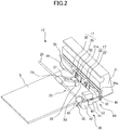
- FIG. 2 is a perspective view illustrating the sheet feeding apparatus 13.
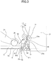
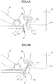
- FIGS. 3 , 4A, and 4B are sectional views illustrating the sheet feeding apparatus 13. In FIGS. 2 to 4B , the flag member 19 is not illustrated.
- the sheet feeding apparatus 13 includes a feeding mechanism 23, a transmission mechanism 40, and a moving mechanism 60.
- the transmission mechanism 40 serves as a transmission part; and transmits driving force of a motor M, which serves as a driving source, to the feeding mechanism 23.
- the moving mechanism 60 serves as a moving part, and moves later-described abutment members 52.
- the feeding mechanism 23 includes a rotation shaft 25, a holder 24 which is swingably supported by the rotation shaft 25, and a pickup roller 26 which serves as a feeding part and is rotatably supported by the end of the holder 24.
- the holder 24 includes a drivetrain 27 disposed between the rotation shaft 25 and the pickup roller 26.
- the drivetrain 27 is constituted by gears.
- the rotation of the rotation shaft 25 is transmitted to the pickup roller 26 via the drivetrain 27.
- the holder 24 can swing in accordance with the height of sheets stacked on the stacking surface 8a (see FIG. 1 ) of the feeding tray 8.
- the conveyance guide 21 which serves as a guide part, has a sloping surface 21a.
- the angle ⁇ 1 of the sloping surface 21a with respect to the stacking surface 8a of the feeding tray 8 is obtuse on the pickup roller side.
- the sloping surface 21a which serves as a separation part and a separation surface is provided with a sloping-surface cover 49.
- the sloping-surface cover 49 has its low resistance to the conveyance, and thus smoothly guides the sheet S to the conveyance roller pair 17.
- the conveyance guide 21 supports separation members 50.
- the separation members 50 are urged by separation springs 51 such that the separation members 50 protrude from the sloping surface 21a and the sloping-surface cover 49 toward the pickup roller 26.
- the separation members 50 and the separation springs 51 are each provided three to be symmetric to each other.
- a center of the conveyance path in the width direction serves as a center of the symmetry.
- the separation members 50, the sloping-surface cover 49, and the conveyance guide 21 constitute a separation sloping-surface portion 70.
- each of the separation members 50 On a surface 50a of each of the separation members 50, a plurality of convexities and concavities are formed along the sloping surface 21a.
- the separation members 50 can move between a protruding position and a retracting position. When the separation members 50 are positioned at the protruding position, the separation members 50 protrude from the sloping surface 21a and the sloping-surface cover 49 toward the pickup roller 26. When the separation members 50 are positioned at the retracting position, the separation members 50 are retracted in the inside of the sloping surface 21a. When the sheet S is fed by the pickup roller 26, the separation members 50 are moved from the protruding position to the retracting position against the urging force of the separation springs 51. In this time, the sheet S can be effectively separated from another sheet because the convexities and concavities are formed on the surface 50a of each of the separation members 50.
- the conveyance roller pair 17 is disposed in the downstream of the separation members 50 in a sheet traveling direction D.
- the conveyance roller pair 17 has a driving roller 29 and a driven roller 30.
- the driven roller 30 is urged toward the driving roller 29 by a spring (not illustrated), with a predetermined pressure.
- a rotation shaft 29a of the driving roller 29 is rotatably supported by a bearing 31 which is fit in the conveyance guide 21.
- the sloping surface 21a is provided with openings 21b serving as an opening part, which accommodate respective abutment members 52 serving as an abutment part.
- the openings 21b and the abutment members 52 are each provided two to be symmetric to each other.
- a center of the conveyance path in the width direction serves as a center of the symmetry.
- the right and left abutment members 52 are formed on a pivot shaft 52a, which serves as a shaft member. Between the right and left abutment members 52, there is formed a stopper 56 which is bent in a U shape.
- the abutment members 52 can pivot between a protruding position illustrated in FIG. 4A and a retracting position illustrated in FIG. 4B , with the rotation of the pivot shaft 52a.
- the abutment members 52 each have an abutment surface 57 which can abut against the leading edge of the sheet S.
- the abutment surface 57 which serves as an abutment area, is shaped like steps having a plurality of curved surfaces.
- the abutment surface 57 is positioned more away from the pickup roller 26 than the separation sloping-surface portion 70. That is, the abutment surface 57 does not protrude toward the pickup roller 26 from the sloping surface 21a.
- the abutment surface 57 of each of the abutment members 52 does not contact the sheet S.
- the abutment members 52 do not interfere with the sheet S, and thus the sheet S can be reliably separated.
- FIG. 5 is an exploded perspective view of the conveyance guide 21 and the pivot shaft 52a as viewed from the bottom face side of the printer 10.
- the conveyance guide 21 is provided with a plurality of U-shaped cutouts 21c whose lower portions are opened.
- the U-shaped cutouts 21c pivotably support an upper portion of the pivot shaft 52a.
- the pivot shaft 52a is provided with positioning ribs 52c extending in a radial direction.
- the positioning ribs 52c are arranged so as to hold a corresponding U-shaped cutout 21c therebetween, and thus the pivot shaft 52a is positioned in its axial direction.
- the exterior cover 90 includes a base plate 90a of the sheet feeding apparatus 13 (see FIG. 1 ).
- the base plate 90a includes support portions 91 protruding upward.
- the support portions 91 have U-shaped cutouts 91a whose upper portions are opened.
- the U-shaped cutouts 91a pivotably support a lower portion of the pivot shaft 52a. That is, as illustrated in FIG. 7 , the upper portion of the pivot shaft 52a is supported by the U-shaped cutouts 21c formed in the conveyance guide 21, and the lower portion of the pivot shaft 52a is supported by the U-shaped cutouts 91a formed in the support portions 91. With this structure, the pivot shaft 52a is positioned in a radial direction.
- the support portions 91 are provided three, and aligned with each other on the base plate 90a, along the axial direction of the pivot shaft 52a.
- three of the U-shaped cutouts 21c (see FIG. 5 ) formed in the conveyance guide 21 are positioned at positions corresponding to the three support portions 91.
- a cushioning member 92 is disposed, as an elastic member, on the base plate 90a so as to be positioned under the pivot shaft 52a, which is supported by the support portions 91.
- the cushioning member 92 is stuck on the base plate 90a with an adhesive tape (not illustrated); and is compressed in an outer shape of the pivot shaft 52a, between the base plate 90a and the pivot shaft 52a supported by the support portions 91.
- the cushioning member 92 does not prevent the abutment members 52 from pivoting between the protruding position and the retracting position.
- the cushioning member 92 is made of sponge.
- the material of the cushioning member 92 is not limited to this, and may be another material, such as rubber.
- the cushioning member 92 is disposed between the two abutment members 52 in a state where the pivot shaft 52a is supported by the support portions 91.
- the cushioning member 92 is disposed between the abutment members 52 and the base plate 90a, which is a part of the exterior cover 90.
- the arrangement of the cushioning member 92 will be more specifically described below.
- a lower surface 90c of the base plate 90a is provided with foot portions 93, which are a first foot portion, a second foot portion, and a third foot portion.
- the foot portions 93 support the sheet feeding apparatus 13 or the printer 10.
- one foot portion 93 When viewed in a direction orthogonal to the lower surface 90c, one foot portion 93 is not disposed on a line passing through the others. Specifically, two of the foot portions 93 are disposed on the front side of the printer 10, and one of the foot portions 93 is disposed on the back side of the printer 10. A straight line 95 which connects the foot portions 93 forms a triangle, and the cushioning member 92 is positioned inside the triangle. With the cushioning member 92 arranged in this manner, vibration of the abutment members 52 can be suppressed from propagating to the exterior cover 90. That is, the vibration can be effectively suppressed from propagating to the foot portions 93 through the base plate 90a of the exterior cover 90. As a result, a table or the like on which the printer 10 is placed can be prevented from vibrating and making noise.
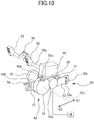
- the transmission mechanism 40 includes an input gear 41, a control gear 42, an output gear 43, a solenoid 44, and a locking pawl 58.
- the transmission mechanism 40 can transmit driving force generated by a motor M, to the pickup roller 26 (see FIG. 2 ).
- the motor M rotates in only one direction, and generates the driving force.
- the input gear 41 is coupled with the motor M.
- the output gear 43 is fixed to the rotation shaft 25 (see FIG. 2 ) used to rotate the pickup roller 26.
- the outer circumferential surfaces of the input gear 41 and the output gear 43 are each provided with a gear teeth portion over the whole circumference.
- the control gear 42 which serves as a rotary member, includes a locked portion 42b, a first teeth-free portion 59a, and a second teeth-free portion 59b.
- the locked portion 42b is capable of locking with a pawl portion 58a of the locking pawl 58.
- the first teeth-free portion 59a and the second teeth-free portion 59b are portions of the control gear 42 in which a gear teeth portion is not formed on an outer circumferential surface thereof.
- the locked portion 42b, the first teeth-free portion 59a, and the second teeth-free portion 59b are formed along the axial direction of the control gear 42, at positions different from each other.
- the gear teeth portion is formed on a portion of the outer circumferential surface of the control gear 42, other than the first teeth-free portion 59a.
- the gear teeth portion is formed on a portion of the outer circumferential surface of the control gear 42, other than the second teeth-free portion 59b.
- the control gear 42 is positioned at a rotational position (phase) which is a standby position.
- the input gear 41 faces the first teeth-free portion 59a
- the output gear 43 faces the second teeth-free portion 59b.
- the driving force is not transmitted between the input gear 41 and the control gear 42, and between the control gear 42 and the output gear 43.
- the locking pawl 58 is urged by a spring (not illustrated) toward a direction in which the locked portion is locked.
- the locking pawl 58 moves against the urging force of the spring so that the locked portion 42b is unlocked. That is, when the solenoid 44 is operated, the lock state between the locking pawl 58 and the locked portion 42b of the control gear 42 is released.
- the control gear 42 includes a compression spring (not illustrated).
- the moving mechanism 60 includes a link member 53.
- the link member 53 has an engage hole 53a, which can be engaged with an engage portion52b.
- the engage portion 52b extends from one end of the pivot shaft 52a, to which the abutment members 52 are fixed; and is formed like a crank. That is, the engage portion 52b is shifted from the pivot shaft 52a in a radial direction of the pivot shaft 52a.
- the link member 53 can move toward a direction which is indicated by an arrow E1, and a direction which is indicated by an arrow E2 and opposite to the direction indicated by the arrow E1.
- the link member 53 is urged toward the direction indicated by the arrow E1, by a link spring 54, which serves as an urging member.
- the control gear 42 is provided with a semicircular protrusion portion 62 on a side of the control gear 42 which faces the link member 53. From the protrusion portion 62, a boss portion 42a extends in the axial direction of the protrusion portion 62. The boss portion 42a is disposed in a radial direction of the control gear 42, at a position different from a rotation axis 42c of the control gear 42. When the control gear 42 rotates, the boss portion 42a performs circular motion. In addition, a plane portion 62a of the protrusion portion 62 is formed so as to contact with a slide surface 45b of a return lever 45.
- the return lever 45 is supported around a pivot shaft 45a so that the return lever 45 can pivot on the pivot shaft 45a.
- the return lever 45 is urged by a lever spring 46 toward the plane portion 62a.
- the link member 53 includes a semicircular boss engage portion 53b which can engage with the boss portion 42a, and a cam portion 53c on which the boss portion 42a slides while pressing it.
- the boss portion 42a which serves as a positioning portion, engages with the boss engage portion 53b, which serves as an engage portion; and thereby positions the abutment members 52 at the protruding position.
- the control gear 42 is positioned at the standby position, the boss portion 42a is engaged with the boss engage portion 53b, and the slide surface 45b of the return lever 45 abuts against the plane portion 62a.
- the solenoid 44 is in its non-operation state, and the pawl portion 58a of the locking pawl 58 locks the locked portion 42b of the control gear 42, as illustrated in FIG. 10 .
- the control gear 42 is reliably held at the standby position. In this time, the first teeth-free portion 59a of the control gear 42 faces the input gear 41, and the second teeth-free portion 59b faces the output gear 43.
- the abutment members 52 are positioned at the protruding position, as illustrated in FIG. 4A .
- a user inserts the sheet S from the insertion opening 81 (see FIG. 1 ), and abuts the leading edge of the sheet S against the abutment surface 57 of each of the abutment members 52.
- the controller 80 drives the motor M in one direction, and moves the locking pawl 58 by operating the solenoid 44 for a predetermined time. Then, the lock state between the pawl portion 58a of the locking pawl 58 and the locked portion 42b of the control gear 42 is released, and the compression spring (not illustrated) included in the control gear 42 causes the control gear 42 to start rotating in one direction.
- the control gear 42 rotates, the input gear 41 meshes with the gear teeth portion of the control gear 42, so that the driving force of the motor M is transmitted to the control gear 42 via the input gear 41.
- the abutment members 52 fixed to the pivot shaft 52a move from the protruding position to the retracting position.
- the link member 53 moves relatively faster, when the engagement between the boss portion 42a and the boss engage portion 53b is released, because of the urging force of the link spring 54.
- the abutment members 52 move relatively faster from the protruding position to the retracting position.
- the abutment members 52 move from the protruding position to the retracting position in tens of milliseconds.
- the output gear 43 starts to mesh with the gear teeth portion of the control gear 42. That is, since the second teeth-free portion 59b of the control gear 42 is formed in a wider range than the first teeth-free portion 59a, the output gear 43 remains facing the second teeth-free portion 59b until the control gear 42 rotates by a predetermined angle from the standby position. Thus, the sheet S is not fed by the pickup roller 26 until the abutment members 52 move to the retracting position.
- the pickup roller 26 rotates and feeds the sheet S from the stacking surface 8a.
- the boss portion 42a formed on the control gear 42, slidingly contacts the cam portion 53c of the link member 53 before the control gear 42 completes its one rotation performed from the standby position. Since the boss portion 42a presses the cam portion 53c while slidingly contacting the cam portion 53c, the link member 53 is moved, as illustrated in FIG. 11A , toward a direction indicated by an arrow E2 against the urging force of the link spring 54.
- the link member 53 is moved, in this manner, toward the direction indicated by the arrow E2, the abutment members 52 gradually move from the retracting position toward the protruding position.
- the boss portion 42a engages with the boss engage portion 53b, and the abutment members 52 are positioned at the protruding position again.
- the slide surface 45b of the return lever 45 presses the plane portion 62a of the protrusion portion 62 toward the rotation axis 42c of the control gear 42, in response to the urging force of the lever spring 46.
- the boss engage portion 53b also presses the boss portion 42a toward the rotation axis 42c of the control gear 42, in response to the urging force of the link spring 54.
- the urging direction of the lever spring 46 and the urging direction of the link spring 54 are substantially orthogonal to each other.
- the stop control for the control gear 42 for each one rotation that is, the one-rotation control for the control gear 42 is performed as described above.
- the sheet S is moved at least until the leading edge of the sheet S is nipped by the conveyance roller pair 17.
- the sheet S nipped by the conveyance roller pair 17 is conveyed downstream in the sheet conveyance direction, by the conveyance roller pair 17.
- the pickup roller 26 is in contact with the sheet S which is being conveyed, and thus is rotated by the sheet S.
- the motor M is rotated until the job is completed, and the solenoid 44 is operated at a timing when each sheet S is fed.
- the boss portion 42a performs a series of operations; that is, the boss portion 42a is released from the engagement with the boss engage portion 53b, presses the cam portion 53c, and engages with the boss engage portion 53b again.
- the abutment members 52 move from the protruding position to the retracting position.
- the abutment members 52 are moved from the retracting position to the protruding position by the link member 53 which is being pressed by the boss portion 42a along the cam portion 53c. In this time, the abutment members 52 move slower than when moving from the protruding position to the retracting position.
- the abutment members 52 return to the protruding position every time each sheet S is fed, the sheet S can be prevented from leaning on the separation sloping-surface portion 70 during a job, and this leads to reduction in failure of the feeding. Furthermore, even though the motor M rotates in only one direction, the abutment members 52 can be moved between the protruding position and the retracting position by the simple mechanical configuration, in synchronization with the feeding of the sheet S. This can achieve cost reduction and downsizing.
- the one-rotation control for the control gear 42 is achieved by using the solenoid 44, the first teeth-free portion 59a, and the second teeth-free portion 59b.
- the present disclosure is not limited to this configuration.
- the first teeth-free portion 59a of the control gear 42 may not be formed, the input gear 41 may always mesh with the control gear 42, and a torque limiter may be provided between the input gear 41 and the rotation shaft of the input gear 41.
- the one-rotation control for the control gear 42 may be performed by using an electromagnetic clutch or another clutch mechanism.
- each sheet may be fed while the control gear 42 makes not one rotation, but two or more rotations.
- the feeding tray 8 may be provided with an intermediate plate which can move up and down, and the sheet intermediate plate may move up and down in response to the one-rotation control for the control gear 42.
- the rotation shaft 25 may be provided with a cam, and the sheet supporting portion may be provided with a cam follower which can engage with the cam.
- the holder 24, which raises and lowers the pickup roller 26, may swing for each sheet.
- the present embodiment has been described for the electrophotographic printer 10, but the present invention is not limited to this.
- the present invention may be applied to other image forming apparatuses, such as electrophotographic full-color printers, copying machines, facsimiles, and multifunction products.
- the present invention may also be applied to ink-jet image forming apparatuses that form images on sheets by injecting ink from their nozzles.
- the sheet feeding apparatus 13 is disposed in the printer 10.
- the present disclosure is not limited to this.
- the sheet feeding apparatus of the present embodiment may be applied to an option feeder which is connected to a bottom face or a side face of the printer 10.
- a sheet feeding apparatus (13) includes a stacking part (8), a feeding part (26), an abutment part (52) comprising an abutment area (57), the abutment part (52) being configured to move between a first position and a second position, a transmission part (40) comprising a rotary member (42), the rotary member (42) being configured to be stopped every one rotation, and a moving part (60) configured to move the abutment part (52) in response to rotation of the rotary member (42) such that the abutment part (52) positions at the first position in a case where the rotary member (42) is stopped, and the abutment part (52) moves from the first position to the second position and from the second position to the first position while the rotary member (42) makes one rotation.
Landscapes
- Engineering & Computer Science (AREA)
- Mechanical Engineering (AREA)
- Sheets, Magazines, And Separation Thereof (AREA)
- Physics & Mathematics (AREA)
- General Physics & Mathematics (AREA)
Claims (17)
- Appareil d'alimentation en feuille (13), comprenant :une partie d'empilement (8) sur laquelle est empilée une feuille ;une partie d'alimentation (26) configurée pour alimenter la feuille empilée sur la partie d'empilement (8) ;une partie de séparation (21a) configurée pour séparer la feuille d'une autre feuille tout en contactant de manière glissante la feuille alimentée par la partie d'alimentation (26) ; etune partie de butée (52) comprenant une zone de butée (57) contre laquelle est en butée un bord de tête de la feuille empilée sur la partie d'empilement (8), la partie de butée (52) étant configurée pour se déplacer entre une première position et une seconde position, la première position étant une position au niveau de laquelle au moins une partie de la zone de butée (57) fait saillie de la partie de séparation (21a) en direction de la partie d'alimentation (26), la seconde position étant une position au niveau de laquelle la zone de butée (57) ne fait pas saillie de la partie de séparation (21a) en direction de la partie d'alimentation (26) ; caractérisé parune partie de transmission (40) comprenant un élément rotatif (42) et configurée pour transmettre une puissance d'entraînement d'une source d'entraînement (M) à la partie d'alimentation (26) par le biais de l'élément rotatif (42), l'élément rotatif (42) étant configuré pour être arrêté à chaque rotation ; etune partie de déplacement (60) configurée pour déplacer la partie de butée (52) en réponse à une rotation de l'élément rotatif (42) de sorte que(1) la partie de butée (52) se positionne au niveau de la première position dans un cas dans lequel l'élément rotatif (42) est arrêté, et(2) la partie de butée (52) se déplace de la première position à la seconde position et de la seconde position à la première position tandis que l'élément rotatif (42) effectue une rotation.
- Appareil d'alimentation en feuille (13) selon la revendication 1, dans lequel la partie d'alimentation (26) alimente une feuille empilée sur la partie d'empilement (8) en réponse à une rotation de l'élément rotatif (42), et
dans lequel la partie de butée (52) se déplace de la première position à la seconde position avant que la feuille alimentée par la partie d'alimentation (26) n'atteigne la partie de butée (52), et se déplace de la seconde position à la première position tandis que la feuille passe la partie de butée (52). - Appareil d'alimentation en feuille (13) selon la revendication 1 ou 2, dans lequel la partie de butée (52) se déplace plus lentement lorsqu'elle se déplace de la seconde position à la première position que lorsqu'elle se déplace de la première position à la seconde position.
- Appareil d'alimentation en feuille (13) selon l'une quelconque des revendications 1 à 3, dans lequel la partie de déplacement (60) comprend
une partie de positionnement (42a) disposée sur l'élément rotatif (42),
un élément de liaison (53) comprenant une partie de prise (53b) configurée pour venir en prise avec la partie de positionnement (42a), l'élément de liaison (53) étant relié à la partie de butée (52), et
un élément de sollicitation (54) configuré pour solliciter l'élément de liaison (53) de sorte que la partie de butée (52) se déplace en direction de la seconde position, et
dans lequel la partie de butée (52) est retenue au niveau de la première position contre une force de sollicitation de l'élément de sollicitation (54) dans un cas dans lequel la partie de positionnement (42a) fait l'objet d'une prise par la partie de prise (53b) de l'élément de liaison (53). - Appareil d'alimentation en feuille (13) selon la revendication 4, dans lequel la partie de positionnement (42a) fait l'objet d'une prise par la partie de prise (53b) dans un cas dans lequel l'élément rotatif (42) est arrêté.
- Appareil d'alimentation en feuille (13) selon la revendication 4 ou 5, dans lequel la partie de positionnement (42a) est disposée au niveau d'une position différente à partir d'un axe de rotation (42c) de l'élément rotatif (42) dans une direction radiale de l'élément rotatif (42).
- Appareil d'alimentation en feuille (13) selon l'une quelconque des revendications 4 à 6, dans lequel l'élément de liaison (53) comprend une partie came (53c) configurée pour être pressée par la partie de positionnement (42a), et
dans lequel la partie de positionnement (42a) est libérée de la partie de prise (53b), presse la partie came (53c) et fait l'objet d'une prise par la partie de prise (53b) tandis que l'élément rotatif (42) effectue une rotation. - Appareil d'alimentation en feuille (13) selon la revendication 7, dans lequel l'élément de liaison (53) est déplacé par la force de sollicitation de l'élément de sollicitation (54) de façon à déplacer la partie de butée (52) en direction de la seconde position dans un cas de libération d'une prise entre la partie de positionnement (42a) et la partie de prise (53b),
dans lequel l'élément de liaison (53) déplace la partie de butée (52) de la seconde position en direction de la première position dans un cas dans lequel la partie came (53c) est pressée par la partie de positionnement (42a) contre la force de sollicitation de l'élément de sollicitation (54), et
dans lequel la partie de positionnement (42a) déplace l'élément de liaison (53) en pressant la partie came (53c) de l'élément de liaison (53) à une vitesse plus lente qu'une vitesse à laquelle l'élément de liaison (53) est déplacé par la force de sollicitation de l'élément de sollicitation (54). - Appareil d'alimentation en feuille (13) selon l'une quelconque des revendications 1 à 8, comprenant en outre :une partie de guidage (21) comprenant la partie de séparation (21a) et une partie d'ouverture (21b), la partie d'ouverture (21b) étant configurée pour loger la partie de butée (52) positionnée au niveau de la seconde position ; etun élément de séparation (50) comprenant une pluralité de convexités et de concavités formées le long de la partie de séparation (21a).
- Appareil d'alimentation en feuille (13) selon l'une quelconque des revendications 1 à 9, dans lequel la partie d'empilement (8) comprend une surface de support (8a) configurée pour supporter la feuille,
dans lequel la partie de séparation comprend une surface de séparation (21a) configurée pour contacter la feuille,
dans lequel un angle (θ1) défini par la surface de support (8a) et la surface de séparation (21a) est obtus d'un côté partie d'alimentation, et
dans lequel un angle (θ2) défini par la surface de support (8a) et la zone de butée (57) de la partie de butée (52) positionnée au niveau de la première position est aigu du côté partie d'alimentation. - Appareil d'alimentation en feuille (13) selon l'une quelconque des revendications 1 à 10, comprenant en outre un moteur servant de source d'entraînement (M) et configuré pour ne tourner que dans un seul sens.
- Appareil d'alimentation en feuille (13) selon l'une quelconque des revendications 1 à 11, comprenant en outre :un élément extérieur (90) configuré pour constituer une partie extérieure de l'appareil d'alimentation en feuille (13) ; etun élément élastique (92) disposé entre la partie de butée (52) et l'élément extérieur (90), et configuré pour se déformer élastiquement.
- Appareil d'alimentation en feuille (13) selon la revendication 12, dans lequel la partie de butée (52) est l'une d'une pluralité de parties de butée (52, 52),
l'appareil d'alimentation en feuille (13) comprenant en outre un élément arbre (52a) configuré pour supporter de manière pivotante la pluralité de parties de butée (52, 52),
dans lequel l'élément extérieur (90) comprend une plaque de base (90a) de l'appareil d'alimentation en feuille (13), et
dans lequel l'élément élastique (92) est disposé entre l'élément arbre (52a) et la plaque de base (90a). - Appareil d'alimentation en feuille (13) selon la revendication 13, dans lequel la plaque de base (90a) comprend une partie de support (91) configurée pour supporter de manière pivotante l'élément arbre (52a), et
dans lequel l'élément élastique (92) est comprimé entre l'élément arbre (52a) supporté par la partie de support (91) et la plaque de base (90a). - Appareil d'alimentation en feuille (13) selon la revendication 13 ou 14, l'appareil d'alimentation en feuille (13) comprenant en outre une première partie pied (93), une deuxième partie pied (93) et une troisième partie pied (93) disposées individuellement sur une surface inférieure de la plaque de base (90a) et configurées pour supporter l'appareil d'alimentation en feuille (13),
dans lequel la troisième partie pied (93) n'est pas disposée sur une ligne passant par la première partie pied (93) et la deuxième partie pied (93), lorsqu'observée dans une direction orthogonale qui est orthogonale à la surface inférieure, et
dans lequel l'élément élastique (92) est disposé à l'intérieur d'un triangle (95), lorsqu'observé dans la direction orthogonale, défini en reliant la première partie pied (93), la deuxième partie pied (93) et la troisième partie pied (93). - Appareil d'alimentation en feuille (13) selon l'une quelconque des revendications 12 à 15, dans lequel l'élément élastique (92) est constitué d'éponge.
- Appareil de formation d'image, comprenant :l'appareil d'alimentation en feuille (13) selon l'une quelconque des revendications 1 à 16 ; etune partie de formation d'image (14) configurée pour former une image sur la feuille alimentée par l'appareil d'alimentation en feuille (13).
Applications Claiming Priority (3)
| Application Number | Priority Date | Filing Date | Title |
|---|---|---|---|
| JP2017159736A JP6971708B2 (ja) | 2017-08-22 | 2017-08-22 | シート給送装置及び画像形成装置 |
| JP2017159735A JP6918635B2 (ja) | 2017-08-22 | 2017-08-22 | シート給送装置及び画像形成装置 |
| JP2017230515A JP7039267B2 (ja) | 2017-11-30 | 2017-11-30 | 画像形成装置 |
Publications (2)
| Publication Number | Publication Date |
|---|---|
| EP3447012A1 EP3447012A1 (fr) | 2019-02-27 |
| EP3447012B1 true EP3447012B1 (fr) | 2020-12-09 |
Family
ID=63173955
Family Applications (1)
| Application Number | Title | Priority Date | Filing Date |
|---|---|---|---|
| EP18187554.3A Active EP3447012B1 (fr) | 2017-08-22 | 2018-08-06 | Appareil d'alimentation de feuilles et appareil de formation d'images |
Country Status (4)
| Country | Link |
|---|---|
| US (1) | US10543997B2 (fr) |
| EP (1) | EP3447012B1 (fr) |
| KR (1) | KR102367038B1 (fr) |
| CN (1) | CN109422112B (fr) |
Families Citing this family (5)
| Publication number | Priority date | Publication date | Assignee | Title |
|---|---|---|---|---|
| JP6921628B2 (ja) * | 2017-05-24 | 2021-08-18 | キヤノン株式会社 | シート給送装置及び画像形成装置 |
| JP7616558B2 (ja) * | 2020-10-12 | 2025-01-17 | 株式会社リコー | 給送装置及び画像形成装置 |
| JP7665126B2 (ja) | 2020-11-05 | 2025-04-21 | ブラザー工業株式会社 | 画像処理装置 |
| CN113335962A (zh) * | 2021-07-02 | 2021-09-03 | 广东吉鼎机械科技有限公司 | 一种地板贴皮机的面片输送机构 |
| JP2024127166A (ja) * | 2023-03-09 | 2024-09-20 | セイコーエプソン株式会社 | 印刷装置 |
Family Cites Families (21)
| Publication number | Priority date | Publication date | Assignee | Title |
|---|---|---|---|---|
| JP2648518B2 (ja) | 1989-08-30 | 1997-09-03 | 三田工業株式会社 | 給紙装置 |
| US5648808A (en) | 1991-06-10 | 1997-07-15 | Canon Kabushiki Kaisha | Automatic sheet feeding apparatus |
| JP2925368B2 (ja) | 1991-07-25 | 1999-07-28 | キヤノン株式会社 | シート給送装置及び画像形成装置 |
| ATE208279T1 (de) | 1992-07-31 | 2001-11-15 | Canon Kk | Blattfördervorrichtung |
| JPH06144624A (ja) | 1992-11-04 | 1994-05-24 | Ricoh Co Ltd | 画像形成装置の手差し給紙装置 |
| JP3119754B2 (ja) | 1992-12-24 | 2000-12-25 | キヤノン株式会社 | 記録装置 |
| US6877738B2 (en) * | 2001-05-10 | 2005-04-12 | Canon Kabushiki Kaisha | Sheet material feed apparatus and recording apparatus |
| US7665725B2 (en) * | 2007-01-22 | 2010-02-23 | Xerox Corporation | Registration gate for multi sheet inserter tray |
| JP5171462B2 (ja) | 2008-07-31 | 2013-03-27 | キヤノン株式会社 | シート給送装置及び画像形成装置 |
| JP5178478B2 (ja) | 2008-11-28 | 2013-04-10 | キヤノン株式会社 | シート給送装置及び画像形成装置 |
| JP5743757B2 (ja) | 2010-08-06 | 2015-07-01 | キヤノン株式会社 | シート給送装置、画像形成装置及び画像読取装置 |
| JP5606232B2 (ja) * | 2010-09-13 | 2014-10-15 | キヤノン株式会社 | シート給送装置及び画像形成装置 |
| US8465016B2 (en) * | 2011-01-14 | 2013-06-18 | Hewlett-Packard Development Company, L.P. | Media stack compression with paddle |
| JP5213983B2 (ja) * | 2011-03-30 | 2013-06-19 | キヤノン株式会社 | シート給送装置及び画像形成装置 |
| JP5832123B2 (ja) * | 2011-04-08 | 2015-12-16 | キヤノン株式会社 | シート給送装置及び画像形成装置 |
| JP5911217B2 (ja) | 2011-06-30 | 2016-04-27 | キヤノン株式会社 | 記録装置 |
| JP5980026B2 (ja) | 2012-07-18 | 2016-08-31 | キヤノン株式会社 | シート給送装置及び画像形成装置 |
| JP6213140B2 (ja) * | 2013-10-18 | 2017-10-18 | 富士ゼロックス株式会社 | 収容装置、画像形成装置 |
| US11046097B2 (en) * | 2015-10-28 | 2021-06-29 | Hewlett-Packard Development Company, L.P. | Media retraction |
| JP2016052950A (ja) | 2015-12-10 | 2016-04-14 | キヤノン株式会社 | 給紙装置、および記録装置 |
| JP6924369B2 (ja) * | 2017-05-30 | 2021-08-25 | セイコーエプソン株式会社 | 記録装置 |
-
2018
- 2018-08-02 US US16/052,767 patent/US10543997B2/en active Active
- 2018-08-06 EP EP18187554.3A patent/EP3447012B1/fr active Active
- 2018-08-17 CN CN201810937437.6A patent/CN109422112B/zh active Active
- 2018-08-21 KR KR1020180097153A patent/KR102367038B1/ko active Active
Non-Patent Citations (1)
| Title |
|---|
| None * |
Also Published As
| Publication number | Publication date |
|---|---|
| KR102367038B1 (ko) | 2022-02-24 |
| CN109422112A (zh) | 2019-03-05 |
| US20190062087A1 (en) | 2019-02-28 |
| US10543997B2 (en) | 2020-01-28 |
| EP3447012A1 (fr) | 2019-02-27 |
| CN109422112B (zh) | 2020-11-03 |
| KR20190021178A (ko) | 2019-03-05 |
Similar Documents
| Publication | Publication Date | Title |
|---|---|---|
| EP3447012B1 (fr) | Appareil d'alimentation de feuilles et appareil de formation d'images | |
| US10591853B2 (en) | Moving device and image forming apparatus incorporating the moving device | |
| CN101923297B (zh) | 图像形成设备 | |
| US8577258B2 (en) | Image forming device having regulating member configured to prohibit movement of photosensitive body in lock state | |
| EP2399851B1 (fr) | Appareil d'alimentation en feuille et appareil de formation d'image | |
| JP7375434B2 (ja) | シート給送装置及び画像形成装置 | |
| US11868078B2 (en) | Image forming apparatus including external sheet feed tray with sheet feeder | |
| US11613439B2 (en) | Sheet feeding apparatus and image forming apparatus | |
| US10183822B2 (en) | Sheet feeding unit, sheet feeding apparatus including sheet feeding unit, and image forming apparatus including sheet feeding apparatus | |
| US20080211166A1 (en) | Sheet feeding device and image forming apparatus | |
| JP2018138487A (ja) | シート積載装置、給送装置及び画像形成装置 | |
| US12180024B2 (en) | Image forming apparatus and sheet feeding apparatus | |
| US10087023B2 (en) | Sheet feeding apparatus and image forming apparatus | |
| JP2020172379A (ja) | ホルダーユニットおよびそれを備えた画像形成装置 | |
| JP2010133476A (ja) | 軸継手構造、これを用いた画像形成装置用ユニット、このユニットを用いた画像形成装置 | |
| US11440756B2 (en) | Sheet feeding apparatus and image forming apparatus | |
| US20200231397A1 (en) | Sheet conveying device and image forming apparatus incorporating the sheet conveying device | |
| JP6971708B2 (ja) | シート給送装置及び画像形成装置 | |
| JP7646426B2 (ja) | シート給送装置及び画像形成装置 | |
| US11834292B2 (en) | Driving force transmission device and image forming apparatus | |
| JP2019099307A (ja) | 画像形成装置 | |
| US20260084911A1 (en) | Sheet feeding apparatus and image forming apparatus | |
| JP6918635B2 (ja) | シート給送装置及び画像形成装置 | |
| US8480075B2 (en) | Image forming apparatus | |
| JP2023081541A (ja) | シート給送装置 |
Legal Events
| Date | Code | Title | Description |
|---|---|---|---|
| PUAI | Public reference made under article 153(3) epc to a published international application that has entered the european phase |
Free format text: ORIGINAL CODE: 0009012 |
|
| STAA | Information on the status of an ep patent application or granted ep patent |
Free format text: STATUS: THE APPLICATION HAS BEEN PUBLISHED |
|
| AK | Designated contracting states |
Kind code of ref document: A1 Designated state(s): AL AT BE BG CH CY CZ DE DK EE ES FI FR GB GR HR HU IE IS IT LI LT LU LV MC MK MT NL NO PL PT RO RS SE SI SK SM TR |
|
| AX | Request for extension of the european patent |
Extension state: BA ME |
|
| STAA | Information on the status of an ep patent application or granted ep patent |
Free format text: STATUS: REQUEST FOR EXAMINATION WAS MADE |
|
| 17P | Request for examination filed |
Effective date: 20190827 |
|
| RBV | Designated contracting states (corrected) |
Designated state(s): AL AT BE BG CH CY CZ DE DK EE ES FI FR GB GR HR HU IE IS IT LI LT LU LV MC MK MT NL NO PL PT RO RS SE SI SK SM TR |
|
| GRAP | Despatch of communication of intention to grant a patent |
Free format text: ORIGINAL CODE: EPIDOSNIGR1 |
|
| STAA | Information on the status of an ep patent application or granted ep patent |
Free format text: STATUS: GRANT OF PATENT IS INTENDED |
|
| INTG | Intention to grant announced |
Effective date: 20200629 |
|
| GRAS | Grant fee paid |
Free format text: ORIGINAL CODE: EPIDOSNIGR3 |
|
| GRAA | (expected) grant |
Free format text: ORIGINAL CODE: 0009210 |
|
| STAA | Information on the status of an ep patent application or granted ep patent |
Free format text: STATUS: THE PATENT HAS BEEN GRANTED |
|
| AK | Designated contracting states |
Kind code of ref document: B1 Designated state(s): AL AT BE BG CH CY CZ DE DK EE ES FI FR GB GR HR HU IE IS IT LI LT LU LV MC MK MT NL NO PL PT RO RS SE SI SK SM TR |
|
| REG | Reference to a national code |
Ref country code: GB Ref legal event code: FG4D |
|
| REG | Reference to a national code |
Ref country code: AT Ref legal event code: REF Ref document number: 1343223 Country of ref document: AT Kind code of ref document: T Effective date: 20201215 Ref country code: CH Ref legal event code: EP |
|
| REG | Reference to a national code |
Ref country code: DE Ref legal event code: R096 Ref document number: 602018010565 Country of ref document: DE |
|
| REG | Reference to a national code |
Ref country code: IE Ref legal event code: FG4D |
|
| PG25 | Lapsed in a contracting state [announced via postgrant information from national office to epo] |
Ref country code: RS Free format text: LAPSE BECAUSE OF FAILURE TO SUBMIT A TRANSLATION OF THE DESCRIPTION OR TO PAY THE FEE WITHIN THE PRESCRIBED TIME-LIMIT Effective date: 20201209 Ref country code: FI Free format text: LAPSE BECAUSE OF FAILURE TO SUBMIT A TRANSLATION OF THE DESCRIPTION OR TO PAY THE FEE WITHIN THE PRESCRIBED TIME-LIMIT Effective date: 20201209 Ref country code: GR Free format text: LAPSE BECAUSE OF FAILURE TO SUBMIT A TRANSLATION OF THE DESCRIPTION OR TO PAY THE FEE WITHIN THE PRESCRIBED TIME-LIMIT Effective date: 20210310 Ref country code: NO Free format text: LAPSE BECAUSE OF FAILURE TO SUBMIT A TRANSLATION OF THE DESCRIPTION OR TO PAY THE FEE WITHIN THE PRESCRIBED TIME-LIMIT Effective date: 20210309 |
|
| REG | Reference to a national code |
Ref country code: AT Ref legal event code: MK05 Ref document number: 1343223 Country of ref document: AT Kind code of ref document: T Effective date: 20201209 |
|
| PG25 | Lapsed in a contracting state [announced via postgrant information from national office to epo] |
Ref country code: BG Free format text: LAPSE BECAUSE OF FAILURE TO SUBMIT A TRANSLATION OF THE DESCRIPTION OR TO PAY THE FEE WITHIN THE PRESCRIBED TIME-LIMIT Effective date: 20210309 Ref country code: SE Free format text: LAPSE BECAUSE OF FAILURE TO SUBMIT A TRANSLATION OF THE DESCRIPTION OR TO PAY THE FEE WITHIN THE PRESCRIBED TIME-LIMIT Effective date: 20201209 Ref country code: LV Free format text: LAPSE BECAUSE OF FAILURE TO SUBMIT A TRANSLATION OF THE DESCRIPTION OR TO PAY THE FEE WITHIN THE PRESCRIBED TIME-LIMIT Effective date: 20201209 |
|
| REG | Reference to a national code |
Ref country code: NL Ref legal event code: MP Effective date: 20201209 |
|
| PG25 | Lapsed in a contracting state [announced via postgrant information from national office to epo] |
Ref country code: NL Free format text: LAPSE BECAUSE OF FAILURE TO SUBMIT A TRANSLATION OF THE DESCRIPTION OR TO PAY THE FEE WITHIN THE PRESCRIBED TIME-LIMIT Effective date: 20201209 Ref country code: HR Free format text: LAPSE BECAUSE OF FAILURE TO SUBMIT A TRANSLATION OF THE DESCRIPTION OR TO PAY THE FEE WITHIN THE PRESCRIBED TIME-LIMIT Effective date: 20201209 |
|
| REG | Reference to a national code |
Ref country code: LT Ref legal event code: MG9D |
|
| PG25 | Lapsed in a contracting state [announced via postgrant information from national office to epo] |
Ref country code: SM Free format text: LAPSE BECAUSE OF FAILURE TO SUBMIT A TRANSLATION OF THE DESCRIPTION OR TO PAY THE FEE WITHIN THE PRESCRIBED TIME-LIMIT Effective date: 20201209 Ref country code: CZ Free format text: LAPSE BECAUSE OF FAILURE TO SUBMIT A TRANSLATION OF THE DESCRIPTION OR TO PAY THE FEE WITHIN THE PRESCRIBED TIME-LIMIT Effective date: 20201209 Ref country code: EE Free format text: LAPSE BECAUSE OF FAILURE TO SUBMIT A TRANSLATION OF THE DESCRIPTION OR TO PAY THE FEE WITHIN THE PRESCRIBED TIME-LIMIT Effective date: 20201209 Ref country code: PT Free format text: LAPSE BECAUSE OF FAILURE TO SUBMIT A TRANSLATION OF THE DESCRIPTION OR TO PAY THE FEE WITHIN THE PRESCRIBED TIME-LIMIT Effective date: 20210409 Ref country code: RO Free format text: LAPSE BECAUSE OF FAILURE TO SUBMIT A TRANSLATION OF THE DESCRIPTION OR TO PAY THE FEE WITHIN THE PRESCRIBED TIME-LIMIT Effective date: 20201209 Ref country code: SK Free format text: LAPSE BECAUSE OF FAILURE TO SUBMIT A TRANSLATION OF THE DESCRIPTION OR TO PAY THE FEE WITHIN THE PRESCRIBED TIME-LIMIT Effective date: 20201209 Ref country code: LT Free format text: LAPSE BECAUSE OF FAILURE TO SUBMIT A TRANSLATION OF THE DESCRIPTION OR TO PAY THE FEE WITHIN THE PRESCRIBED TIME-LIMIT Effective date: 20201209 |
|
| PG25 | Lapsed in a contracting state [announced via postgrant information from national office to epo] |
Ref country code: AT Free format text: LAPSE BECAUSE OF FAILURE TO SUBMIT A TRANSLATION OF THE DESCRIPTION OR TO PAY THE FEE WITHIN THE PRESCRIBED TIME-LIMIT Effective date: 20201209 Ref country code: PL Free format text: LAPSE BECAUSE OF FAILURE TO SUBMIT A TRANSLATION OF THE DESCRIPTION OR TO PAY THE FEE WITHIN THE PRESCRIBED TIME-LIMIT Effective date: 20201209 |
|
| REG | Reference to a national code |
Ref country code: DE Ref legal event code: R097 Ref document number: 602018010565 Country of ref document: DE |
|
| PG25 | Lapsed in a contracting state [announced via postgrant information from national office to epo] |
Ref country code: IS Free format text: LAPSE BECAUSE OF FAILURE TO SUBMIT A TRANSLATION OF THE DESCRIPTION OR TO PAY THE FEE WITHIN THE PRESCRIBED TIME-LIMIT Effective date: 20210409 |
|
| PLBE | No opposition filed within time limit |
Free format text: ORIGINAL CODE: 0009261 |
|
| STAA | Information on the status of an ep patent application or granted ep patent |
Free format text: STATUS: NO OPPOSITION FILED WITHIN TIME LIMIT |
|
| PG25 | Lapsed in a contracting state [announced via postgrant information from national office to epo] |
Ref country code: AL Free format text: LAPSE BECAUSE OF FAILURE TO SUBMIT A TRANSLATION OF THE DESCRIPTION OR TO PAY THE FEE WITHIN THE PRESCRIBED TIME-LIMIT Effective date: 20201209 Ref country code: IT Free format text: LAPSE BECAUSE OF FAILURE TO SUBMIT A TRANSLATION OF THE DESCRIPTION OR TO PAY THE FEE WITHIN THE PRESCRIBED TIME-LIMIT Effective date: 20201209 |
|
| 26N | No opposition filed |
Effective date: 20210910 |
|
| PG25 | Lapsed in a contracting state [announced via postgrant information from national office to epo] |
Ref country code: DK Free format text: LAPSE BECAUSE OF FAILURE TO SUBMIT A TRANSLATION OF THE DESCRIPTION OR TO PAY THE FEE WITHIN THE PRESCRIBED TIME-LIMIT Effective date: 20201209 Ref country code: SI Free format text: LAPSE BECAUSE OF FAILURE TO SUBMIT A TRANSLATION OF THE DESCRIPTION OR TO PAY THE FEE WITHIN THE PRESCRIBED TIME-LIMIT Effective date: 20201209 |
|
| PG25 | Lapsed in a contracting state [announced via postgrant information from national office to epo] |
Ref country code: ES Free format text: LAPSE BECAUSE OF FAILURE TO SUBMIT A TRANSLATION OF THE DESCRIPTION OR TO PAY THE FEE WITHIN THE PRESCRIBED TIME-LIMIT Effective date: 20201209 |
|
| REG | Reference to a national code |
Ref country code: CH Ref legal event code: PL |
|
| PG25 | Lapsed in a contracting state [announced via postgrant information from national office to epo] |
Ref country code: MC Free format text: LAPSE BECAUSE OF FAILURE TO SUBMIT A TRANSLATION OF THE DESCRIPTION OR TO PAY THE FEE WITHIN THE PRESCRIBED TIME-LIMIT Effective date: 20201209 |
|
| REG | Reference to a national code |
Ref country code: BE Ref legal event code: MM Effective date: 20210831 |
|
| PG25 | Lapsed in a contracting state [announced via postgrant information from national office to epo] |
Ref country code: LI Free format text: LAPSE BECAUSE OF NON-PAYMENT OF DUE FEES Effective date: 20210831 Ref country code: CH Free format text: LAPSE BECAUSE OF NON-PAYMENT OF DUE FEES Effective date: 20210831 |
|
| PG25 | Lapsed in a contracting state [announced via postgrant information from national office to epo] |
Ref country code: IS Free format text: LAPSE BECAUSE OF FAILURE TO SUBMIT A TRANSLATION OF THE DESCRIPTION OR TO PAY THE FEE WITHIN THE PRESCRIBED TIME-LIMIT Effective date: 20210409 Ref country code: LU Free format text: LAPSE BECAUSE OF NON-PAYMENT OF DUE FEES Effective date: 20210806 |
|
| PG25 | Lapsed in a contracting state [announced via postgrant information from national office to epo] |
Ref country code: IE Free format text: LAPSE BECAUSE OF NON-PAYMENT OF DUE FEES Effective date: 20210806 Ref country code: FR Free format text: LAPSE BECAUSE OF NON-PAYMENT OF DUE FEES Effective date: 20210831 Ref country code: BE Free format text: LAPSE BECAUSE OF NON-PAYMENT OF DUE FEES Effective date: 20210831 |
|
| PG25 | Lapsed in a contracting state [announced via postgrant information from national office to epo] |
Ref country code: CY Free format text: LAPSE BECAUSE OF FAILURE TO SUBMIT A TRANSLATION OF THE DESCRIPTION OR TO PAY THE FEE WITHIN THE PRESCRIBED TIME-LIMIT Effective date: 20201209 |
|
| PG25 | Lapsed in a contracting state [announced via postgrant information from national office to epo] |
Ref country code: HU Free format text: LAPSE BECAUSE OF FAILURE TO SUBMIT A TRANSLATION OF THE DESCRIPTION OR TO PAY THE FEE WITHIN THE PRESCRIBED TIME-LIMIT; INVALID AB INITIO Effective date: 20180806 |
|
| PG25 | Lapsed in a contracting state [announced via postgrant information from national office to epo] |
Ref country code: MK Free format text: LAPSE BECAUSE OF FAILURE TO SUBMIT A TRANSLATION OF THE DESCRIPTION OR TO PAY THE FEE WITHIN THE PRESCRIBED TIME-LIMIT Effective date: 20201209 |
|
| PG25 | Lapsed in a contracting state [announced via postgrant information from national office to epo] |
Ref country code: TR Free format text: LAPSE BECAUSE OF FAILURE TO SUBMIT A TRANSLATION OF THE DESCRIPTION OR TO PAY THE FEE WITHIN THE PRESCRIBED TIME-LIMIT Effective date: 20201209 |
|
| PG25 | Lapsed in a contracting state [announced via postgrant information from national office to epo] |
Ref country code: MT Free format text: LAPSE BECAUSE OF FAILURE TO SUBMIT A TRANSLATION OF THE DESCRIPTION OR TO PAY THE FEE WITHIN THE PRESCRIBED TIME-LIMIT Effective date: 20201209 |
|
| PGFP | Annual fee paid to national office [announced via postgrant information from national office to epo] |
Ref country code: DE Payment date: 20250724 Year of fee payment: 8 |
|
| PGFP | Annual fee paid to national office [announced via postgrant information from national office to epo] |
Ref country code: GB Payment date: 20250724 Year of fee payment: 8 |