EP3447175A1 - Distributeur de voile et procédé de distribution de voile - Google Patents
Distributeur de voile et procédé de distribution de voile Download PDFInfo
- Publication number
- EP3447175A1 EP3447175A1 EP18193837.4A EP18193837A EP3447175A1 EP 3447175 A1 EP3447175 A1 EP 3447175A1 EP 18193837 A EP18193837 A EP 18193837A EP 3447175 A1 EP3447175 A1 EP 3447175A1
- Authority
- EP
- European Patent Office
- Prior art keywords
- deflection
- band
- laying
- belt
- nonwoven
- Prior art date
- Legal status (The legal status is an assumption and is not a legal conclusion. Google has not performed a legal analysis and makes no representation as to the accuracy of the status listed.)
- Granted
Links
Images

Classifications
-
- D—TEXTILES; PAPER
- D01—NATURAL OR MAN-MADE THREADS OR FIBRES; SPINNING
- D01G—PRELIMINARY TREATMENT OF FIBRES, e.g. FOR SPINNING
- D01G25/00—Lap-forming devices not integral with machines specified above
-
- D—TEXTILES; PAPER
- D04—BRAIDING; LACE-MAKING; KNITTING; TRIMMINGS; NON-WOVEN FABRICS
- D04H—MAKING TEXTILE FABRICS, e.g. FROM FIBRES OR FILAMENTARY MATERIAL; FABRICS MADE BY SUCH PROCESSES OR APPARATUS, e.g. FELTS, NON-WOVEN FABRICS; COTTON-WOOL; WADDING ; NON-WOVEN FABRICS FROM STAPLE FIBRES, FILAMENTS OR YARNS, BONDED WITH AT LEAST ONE WEB-LIKE MATERIAL DURING THEIR CONSOLIDATION
- D04H1/00—Non-woven fabrics formed wholly or mainly of staple fibres or like relatively short fibres
- D04H1/70—Non-woven fabrics formed wholly or mainly of staple fibres or like relatively short fibres characterised by the method of forming fleeces or layers, e.g. reorientation of fibres
- D04H1/72—Non-woven fabrics formed wholly or mainly of staple fibres or like relatively short fibres characterised by the method of forming fleeces or layers, e.g. reorientation of fibres the fibres being randomly arranged
- D04H1/736—Non-woven fabrics formed wholly or mainly of staple fibres or like relatively short fibres characterised by the method of forming fleeces or layers, e.g. reorientation of fibres the fibres being randomly arranged characterised by the apparatus for arranging fibres
Definitions
- the invention relates to a nonwoven layer and a nonwoven laying method with the features in the preamble of the method and device main claim.
- Such a fleece layer is from the EP 1 828 453 B1 known. It is designed as a so-called stripper and has two main cars (superstructure and laying carriage) and two bands, which are guided over pulleys on the main car. The uppercarriage has a band deflection for both levers.
- the one ribbon is designed as a feed belt, to which a batt on the input side of the batt is transferred. The feed belt with the overlying batt is deflected at the belt deflection by 180 ° in the opposite direction via two rollers, wherein between the two rollers on the belt deflection a single straight band portion of the laying belt is formed.
- the opposite band is also deflected at the band deflection, wherein a single straight band portion of the opposite band is formed.
- These two straight band sections of the two bands are directed obliquely downwards and run parallel, being received and guided on both sides between these two band sections of the pile in the terminal closure.
- the DE 295 18 587 U1 and the EP 1 136 600 A1 also show fleece laying with such a band deflection on the superstructure with two deflection points for the feed belt with the resting pile.
- the non-generic JP S56-26011A shows a crushing device with which a web is creased by slippage between parallel conveyor belts and thereby roughened and thickened.
- the conveyor belts are guided over stationary conveyor rollers.
- the previously known nonwovens are limited in their performance, in particular in the possible throughput speed of the pile. This is the case in particular with very light and sensitive fibrous webs.
- the invention solves this problem with the features in the method and device main claim.
- the nonwoven layer with the claimed strip deflection and the nonwoven laying method have the advantage that the batt can be guided better and more gently and transported over the strip deflection. In addition, higher throughput speeds of the batt are possible than in the prior art.
- first and second and optionally further straight band sections with a corresponding number of three or more deflection points on the band deflection has the advantage that the batt at the critical points better can be performed.
- the three or more deflection points reduce over the prior art, the deflection angle, which is also beneficial for the guidance and the hold of the pile.
- the band and Florumlenkung can be done gradually and thus gently in several steps.
- the last straight band section at the end of the band deflection may already have an inclination in the direction opposite to the feed direction, wherein in this band section the pile can be guided on both sides in the terminal closure of the guide belts.
- this band section it can be solidified so that it can pass safely through the last deflection point despite a there only one-sided pile guide and also with high throughput speed.
- Fliehkraft ceremonie detachments of the batt of only one-sided leading band or structural changes of the batt at such deflection can be avoided with the band deflection invention.
- the claimed nonwoven can be designed for very high belt speeds and web speeds. For this purpose, training as gleichschreiber Leger with the same direction moving main car advantage.
- the pile can be supplied by the superstructure, the laying carriage on a direct and straight path without further deflections and stored by the carriage on a deduction device.
- the nonwoven layer can also have a tensioning device or band length compensation device, which enables decoupling of the main carriage and its kinematics.
- the weight per unit area of the deposited nonwoven can be influenced and if necessary changed over the laying width and / or over the length of fleece.
- the nonwoven may have a buffering function to compensate for fluctuating shrinkage speeds of the batt.
- the claimed nonwoven layer may have the following design features individually or in combination.
- the deflection points on the band deflection can be formed by pulleys.
- the one band or feed belt can have two or more straight band sections with different orientations at the band deflection.
- the straight strip sections of one laying belt or feed belt can be arranged between the deflection points, in particular between deflection rollers.
- the first band section of the one band or feeder band in the feed direction can be directed downwardly in the feed direction and the second or last band section of the one band or feeder band can be directed downwards counter to the feed direction.
- the one band or conveyor belt has at the three or more deflection points in each case a deflection angle ⁇ , ⁇ , ⁇ of less than 90 °.
- the first deflection angle ⁇ and the last, in particular third, deflection angle ⁇ of the one laying belt or feeding belt can each be greater than the middle, in particular the second deflection angle ⁇ .
- the first deflection angle ⁇ can be between 55 ° and 70 °, preferably about 63 °.
- the second deflection angle ⁇ can be between 40 ° and 55 °, preferably about 46 °.
- the third and last deflection angle ⁇ can be between 65 ° and 75 °, preferably about 71 °.
- the band deflection for the other band or counter-band may have three or more pulleys.
- the other tape or counter-belt may have at the tape deflection two or more straight tape sections with different orientations.
- the upper or first straight band sections of both bands may have different orientations and taper towards each other.
- the second or last straight band sections of both bands may be closely adjacent and substantially the same.
- the second or last straight band sections of both bands can be tapered parallel to each other or at an acute angle to each other.
- the superstructure may have at the band deflection a pile guide with several sections in which the batt is guided on one side and then both sides.
- a first open guide section of the pile guide can be formed between the first straight strip sections of both laying belts, wherein the fiber pile is guided on one side at a laying belt or feed belt.
- a following closed guide section of the pile guide can be formed between the second or last straight strip sections of both bands, wherein the batt is guided on both sides in the terminal closure.
- the main car of the nonwoven layer can be arranged parallel to each other and driven and controlled independently.
- the nonwoven layer can have controlled belt drives for the circulating drive of the laying belts.
- the fleece-laying machine may have a tensioning device, in particular with an auxiliary carriage arrangement, for the laying belts, which is coupled to the main carriage.
- the laying belts can be guided in parallel in the area between the main cars in a single straight section and clamp the fiber web (9) between them.
- the nonwoven layer can have a controlled removal device, in particular a draw-off strip, for the deposited multi-ply web formed from the batt.
- the nonwoven layer can be connected downstream of a pile forming device, in particular a card or carding machine.
- the nonwoven layer can be preceded by a web stabilization device, in particular a needle machine.
- the invention relates to a nonwoven layer (1) and a nonwoven laying method.
- the invention also relates to a fiber treatment plant with a nonwoven layer (1) and other plant components.
- the nonwoven layer (1) serves to panel a fed fiber web (9) into a multilayer web (10).
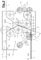
- the nonwoven layer (1) has for this purpose in the embodiment of FIG. 1 two main carriages (2, 3), namely a first main carriage or superstructure (2) and a second main carriage or laying carriage (3), and two endless laying belts (6, 7) guided in a loop over both main carriages (2, 3) on.
- the nonwoven layer (1) further has a transverse or oblique to the movement path of the main carriage (2,3) directed withdrawal device (8) for receiving and removing the multilayer web (10).
- the nonwoven layer (1) may comprise a tensioning device (4).
- the two guided in separate loop paths strips (6,7) come together on the superstructure (2) from different directions, where they are guided over a band deflection (12) described below and emerge from the superstructure (2) in a parallel position, between them the Take up the batt (9) and both sides in the terminal lead.
- the fleece (9) is transferred directly from the parallel strip section to the laying carriage (3) in a straight path.
- the laying belts (6, 7) come apart again and are led away in opposite directions, wherein the released fiber web (9) exits downwards onto the removal device (8) and is deposited there.
- the laying carriage (7) performs this reversing driving movements in the transverse direction to the removal device (8), which performs a preferably coupled with the laying carriage movement forward movement and transported away in scale-like padded fleece (10).
- the main cars (2, 3) are mounted and guided in parallel to one another by means of drives (31) on a rail guide in the frame of the nonwoven layer (1). They each have their own and independently controllable drive (not shown) for their driving movement.
- drives (31) on a rail guide in the frame of the nonwoven layer (1). They each have their own and independently controllable drive (not shown) for their driving movement.
- Leger move the main car (2,3) in the same direction Leger move the main car (2,3) in the same direction, the uppercarriage (2) compared to the laying carriage (3) has double paths and a double speed.
- the movements of the main car (2,3) may be decoupled from each other, so that changes in movement differences, the loop length of the main carriage (2,3) parallel guided bands (6,7) and thereby a pile store can be formed.
- the bands (6,7) may also have independent drives that put them in a controlled orbital motion.
- Such a configuration makes it possible to influence the exit speed of the fibrous web (9) on the laying carriage (3) and, in particular, to decouple it from the traveling speed of the laying carriage (3). This can affect the pile tray on the removal device (8) and the weight per unit area of the fleece (10) and be changed over the laying width of the reciprocating laying carriage (3).
- the solidified end product can receive a desired basis weight distribution or error compensation of pile or consolidation errors can be operated.
- the nonwoven layer (1) can be designed in different ways, eg according to the EP 1 828 453 B1 , or the DE 203 21 834 U1 or the EP 0 517 563 B2 ,
- the difference to the previously known fleece layers consists primarily in the design of the upper carriage (2) and the band deflection (12).
- FIG. 2 shows this band deflection (12) in an enlarged detail view.
- the two laying belts (6, 7) are supplied to the upper carriage (2) and the upper-run band guide (12) at an inlet point (32) separated from each other and from opposite directions.
- the one laying band (6) forms the so-called feed belt, which holds the batt (9) at the in FIG. 1 receives the left input side (35) of the nonwoven layer (1), carries and the superstructure (2) feeds.
- the pile guide may be unilaterally and in an open position, with possibly one or more pressure rollers being present.
- the other laying belt (7) is referred to below as the counter belt.
- Both laying belts (6, 7) are fed in a substantially horizontal orientation to the superstructure (2) and the belt deflection (12).
- the feed belt (6) is at the band deflection (12) from its feed direction (11) deflected in the opposite direction by about 180 ° down to an outlet point (33) on the superstructure.
- both guide strips (6,7) emerge in closely adjacent parallel positions and form a two-sided pile guide region (34) in the sandwich with the batt (9).
- the upper strand (13) and the lower strand (14) of the feed belt (6) are aligned in parallel, wherein the outlet height of the upper carriage (2) and the inlet height of the laying carriage (3) are the same. This results in a deflection angle of 180 °. If the said outlet and inlet heights are different, the lower run (14) may have an inclination to the horizontal, so that the deflection angle of 180 ° may differ slightly. Angular deviation may also occur for other reasons, e.g. when the upper run (13) has a tilt.
- the entry and exit direction of the opposing belt (7) on the superstructure (2) can be rectified and, in particular, horizontal.
- band deflection (12) is effected in between a height offset of the opposite band (7) between the inlet and outlet point (32,33).
- Both above entering levers (6,7) are deflected at the band deflection (12) down and emerge on the upper carriage (2) in a lower position again, in the aforementioned manner preferably the same height as the inlet point on the laying carriage (3) Has.
- the band deflection (12) has three preferably rounded deflection points (15,16,17) for the fibrous web (9) bearing, so-called.
- Floating laying belt (6) The number of deflection points can alternatively be greater and be four, for example.
- the device (9) mediating the device for example a holding or adhesive action by suction or blowing of air, by electrostatic forces or Like. Produced.
- the three deflection points (15, 16, 17) or deflection rollers are arranged at a distance one above the other, wherein the middle deflection point (16) in the feed direction (11) lies further forward than the two other deflection points (15, 17).
- a first straight belt section (22) and between the middle (16) and lower deflection point or deflection roller (17) a second straight belt section (23) of the feed belt (6) formed.
- the in the feed direction (11) first band portion (22) is directed in the feed direction (11) obliquely downward.
- the second band section (23) is directed counter to the feed direction (11) obliquely downward. If the band deflection (12) has more than three deflection points for the feed belt (6), the band section (23) is the last band section in front of the outlet point (33) of the upper carriage (2).
- the feed belt (6) has at the shown three deflection points (15,16,17) each have a deflection angle ⁇ , ⁇ , ⁇ , which is less than 90 °.
- the angles ⁇ , ⁇ , ⁇ give the total deflection angle of e.g. 180 °.
- the first deflection angle ⁇ at the first deflection point or deflection roller (15) and also the last, in particular third deflection angle ⁇ at the last or third deflection point (17) are each greater than the deflection angle ⁇ at the middle one Deflection point (16).
- the first deflection angle ⁇ can be between 55 ° and 70 °, preferably about 63 °.
- the second smaller deflection angle ⁇ can be between 40 ° and 55 °, preferably about 46 °.
- the third and eg last deflection angle ⁇ can be between 65 ° and 75 ° and is preferably about 71 °.
- the aforementioned deflection angles ⁇ , ⁇ , ⁇ can vary in size and assignment.
- the first deflection point or deflection roller (15) on the superstructure (2) against the feed direction (11) to be moved horizontally the other two deflection points or pulleys (16,17) retain their arrangement and training.
- the first deflection angle ⁇ is smaller and the second deflection angle ⁇ greater than in FIG. 2 , possibly also their size ratio changes, in particular reverses.
- the band deflection (12) also has three or more deflection rollers (18 to 21) for the other counter belt (7).
- deflection rollers (18 to 21) for the other counter belt (7).
- the first deflection roller (18) Seen in the direction of feed of the counter belt (7) to the superstructure (2), the first deflection roller (18) is located in front of the middle deflection roller (19) and this again in front of the lower deflection roller (20).
- a first straight band section (24) and between the second or middle deflection roller (19) and the lower and / or third deflection roller (20) a second straight band section (FIG. 25) is formed.
- These straight band sections (24, 25) also have different orientations.
- the counter belt (7) is arranged below and carries the batt (9), wherein the feed belt (6) is arranged above it and covers the batt (9) from above.
- the fibrous web (9) on the upper strand (13) of the feed belt (6) lying on the upper inlet point (32) the upper carriage (2) and the band deflection (12) is supplied.
- obliquely downward straight strip section (22) of the batt (9) is also guided on one side on the feed belt (6) lying.
- the opposite first straight band portion (24) of the opposite band (7) is widely spaced.
- the first straight strip sections (22, 24) of both guide belts (6, 7) have different orientations and run obliquely toward one another.
- the second or last straight strip sections (23, 25) of both guide belts (6, 7) run closely adjacent to one another and are oriented essentially identically, their orientation having a direction component opposite to the feed direction (11).
- the second or last straight band sections (23, 25) form a narrow gap between them, in which the fibrous web (9) is received and possibly guided on both sides with a clamping connection.
- the said band sections (23, 25) can run parallel to one another. You can for the purpose of a Florkkompakt réelle with an acute angle tapered towards each other and thereby a narrowing in the direction of flow direction gap form. The shape and size of the gap can be adjusted and changed.
- the deflection points or the respective shell areas of the pulleys (16,19) of the laying belts (6,7) have a different height, for example, the deflection of the counter-belt (7) is slightly higher.
- the deflection rollers (16,19) may be arranged with their axes at the same height, wherein the roller diameter of the deflection roller (16) is greater than that of the deflection roller (19).
- the fiber web (9) already has the straight belt section (25) of the opposite band (7).
- the straight band portion (25) of the opposite band (7) ends before the straight band portion (23) of the feed belt (6).
- the lower deflection rollers (17, 20) can have roughly equal diameters, wherein the deflection roller (20) of the opposing belt (7) is arranged with its axis somewhat above the axis of the deflection roller (17).
- the deflection rollers (17 to 21) of both laying belts (6, 7) can have adjustable axes and can be adapted to different pile thicknesses or other pile properties.
- the upper carriage (2) on the belt deflection (12) has a pile guide (28) with several, eg two guide sections (29, 30) in which the fiber pile (9) is guided on one side and then on both sides.
- a first open guide section (29) is thereby formed between the first straight strip sections (22, 24) of the laying belts (6, 7), which run like a funnel with a large opening angle of, for example, more than 10 ° at an angle to one another.
- the batt (9) is guided here on one side on the feed belt (6). Due to the moderate deflection angle ⁇ does not lift the open guided batt (9), even at high speeds from the feed belt (6).
- the first open guide section (29) is adjoined by the second closed guide section (30) into which the fiber web (9) dives without guidance over a likewise moderate deflection angle ⁇ .
- the second guide section (30) forms a clamping section between the second straight strip sections (23, 25), between which the fiber web (9) is guided on both sides in the terminal closure.
- the clamping area (30) is directed to the outlet point (33) and ends shortly before.
- the two-sided guide is canceled again, wherein the optionally compacted and additionally stabilized fiber web (9) at the third deflection point (17) again under one-sided guidance on the feed belt (6) moderately deflected by the angle ⁇ and then enters the outlet side (33) on both sides guide region (34) between the rejoined guide belts (6,7).
- the fiber web (9) already has a directional component counter to the feed direction (11) and in the direction of advancing to the laying carriage (3). Even at this deflection point (17) it thus does not detach from the load-bearing feed belt (6) despite one-sided guidance. This is the case even at high speeds and correspondingly high centrifugal forces.
- the nonwoven layer (1) can be preceded on the input side (35) one or more system components.
- This may be, for example, a pile forming device, in particular a card or a carding machine.
- a stretching or compression device, a pile store or the like may be connected upstream of other system components.
- the mentioned system components are not for the sake of clarity shown.
- On the output side of the web laying machine (1) and the delivery point of the discharge device (8) can also be followed by one or more system components.
- This may be a web stabilizer, e.g. a single-stage or multi-stage needling machine, a hydroentangling plant, a thermal consolidation device or the like.
- a compensating belt for buffering and compensating fluctuating nonwoven delivery speeds between the nonwoven layering machine (1) and the solidifying device, in particular the needling machine can also be connected.
- the number of deflection points (15, 16, 17) of the feed belt (6) may be greater than three and may be e.g. four or five, with the number and orientation of the straight band sections (22,23) increases accordingly.
- the size and distribution of the deflection can change.
- the deflection points (18,19,20) of the opposing belt (7) can be adjusted accordingly.
- the pile guide (28) can also receive a larger number of sections, wherein the number of open guide sections (29) and / or the clamping sections (30) can be increased.
- the nonwoven layer (1) can be designed, for example, as an opposite layer, in which the main carriages (2, 3) move in opposite directions and the guide strips (34) are parallel between the two main carriages (2, 3) ) are guided over a frame-fixed deflection, such as a guide roller.
- the clamping device (4) can be omitted or formed in another way, for example, they only has a single auxiliary or tensioning carriage.
- the guidance of the laying belts (6, 7) can be designed in a different way, wherein, for example, one or more additional support carriages are arranged.
- the counter belt (7) can be laid to form a closed pile feed to the input side of the web laying (1) and cover the batt (9) on the feed belt (6).
- Such modifications of the design of the nonwoven layer (1) shown can, for example, according to the EP 1 010 785 , the EP 1 010 786 or the EP 1 010 787 be educated.
- the laying belts (6, 7) in the illustrated embodiment consist of tensile and flexurally elastic plastic webs. They may alternatively consist of other materials and e.g. be designed as a chain or slat bands. Variations are also possible with regard to drive technology.
- the main car (2,3) may have a common drive for their driving movements and may be mechanically coupled to each other by a rope or the like.
- the fleece laying machine (1) has a preferably programmable controller (not shown) to which the various drives of the main carriage (2, 3), the laying belts (6, 7) and the removal device (8) and possibly further components, e.g. a arranged in the inlet region stretching device are connected.
- This control can be connected to a higher-level system control or integrated into it.
- a band deflection (12) of the type shown with several deflection points for at least one laying belt (6,7) can also be present at other locations of a fleece layer (1) or stacker, for example on the laying carriage (3) or on a stationary 180 ° band deflection in the Frame of the fleece layer (1).
Landscapes
- Engineering & Computer Science (AREA)
- Textile Engineering (AREA)
- Preliminary Treatment Of Fibers (AREA)
- Nonwoven Fabrics (AREA)
- Treatment Of Fiber Materials (AREA)
Applications Claiming Priority (3)
| Application Number | Priority Date | Filing Date | Title |
|---|---|---|---|
| DE202012102597U DE202012102597U1 (de) | 2012-07-13 | 2012-07-13 | Vliesleger |
| EP13742410.7A EP2872682B1 (fr) | 2012-07-13 | 2013-07-12 | Distributeur de voile |
| PCT/EP2013/064781 WO2014009520A1 (fr) | 2012-07-13 | 2013-07-12 | Distributeur de voile |
Related Parent Applications (1)
| Application Number | Title | Priority Date | Filing Date |
|---|---|---|---|
| EP13742410.7A Division EP2872682B1 (fr) | 2012-07-13 | 2013-07-12 | Distributeur de voile |
Publications (2)
| Publication Number | Publication Date |
|---|---|
| EP3447175A1 true EP3447175A1 (fr) | 2019-02-27 |
| EP3447175B1 EP3447175B1 (fr) | 2020-11-18 |
Family
ID=48900951
Family Applications (2)
| Application Number | Title | Priority Date | Filing Date |
|---|---|---|---|
| EP18193837.4A Active EP3447175B1 (fr) | 2012-07-13 | 2013-07-12 | Distributeur de voile et procédé de distribution de voile |
| EP13742410.7A Active EP2872682B1 (fr) | 2012-07-13 | 2013-07-12 | Distributeur de voile |
Family Applications After (1)
| Application Number | Title | Priority Date | Filing Date |
|---|---|---|---|
| EP13742410.7A Active EP2872682B1 (fr) | 2012-07-13 | 2013-07-12 | Distributeur de voile |
Country Status (5)
| Country | Link |
|---|---|
| US (1) | US9909236B2 (fr) |
| EP (2) | EP3447175B1 (fr) |
| CN (1) | CN104583477B (fr) |
| DE (1) | DE202012102597U1 (fr) |
| WO (1) | WO2014009520A1 (fr) |
Families Citing this family (3)
| Publication number | Priority date | Publication date | Assignee | Title |
|---|---|---|---|---|
| DE102019104851A1 (de) * | 2019-02-26 | 2020-08-27 | Adler Pelzer Holding Gmbh | Vorrichtung zur Herstellung von Nadelvliesen |
| DE202019105883U1 (de) * | 2019-10-23 | 2021-01-26 | Autefa Solutions Germany Gmbh | Vliesleger und Abschirmeinrichtung |
| FR3138154A1 (fr) * | 2022-07-25 | 2024-01-26 | Andritz Asselin-Thibeau | Dispositif tampon pour adapter la vitesse de sortie d’une nappe d’un étaleur nappeur à la vitesse d’entrée d’un dispositif de traitement de la nappe en aval de l’étaleur nappeur |
Citations (2)
| Publication number | Priority date | Publication date | Assignee | Title |
|---|---|---|---|---|
| EP1367166A1 (fr) * | 2002-05-28 | 2003-12-03 | Asselin | Chariot mobile d'entrée d'étaleur-nappeur et étaleur-nappeur équipé dudit chariot |
| EP1828453B1 (fr) * | 2004-12-23 | 2008-06-25 | AUTEFA automation GmbH | Distributeur de voile et procede de guidage d'un poil |
Family Cites Families (51)
| Publication number | Priority date | Publication date | Assignee | Title |
|---|---|---|---|---|
| US3232297A (en) * | 1961-05-12 | 1966-02-01 | American Mach & Foundry | Pneumatic separator in tobacco feed |
| US3737051A (en) * | 1972-01-07 | 1973-06-05 | Tokyo Shibaura Electric Co | Apparatus for aligning edges of stacked sheets in the vertical direction |
| FR2234395B1 (fr) * | 1973-06-19 | 1976-09-17 | Asselin Robert | |
| DE2727043C3 (de) * | 1976-06-16 | 1980-05-08 | Fuji Photo Film Co., Ltd., Ashigara, Kanagawa (Japan) | Vorrichtung zum Drucken von Markierungen auf Stahlplatten |
| US4357739A (en) * | 1977-03-07 | 1982-11-09 | Hergeth Kg Maschinenfabrik Und Apparatebau | Apparatus for laying fiber fleeces or the like on a moving withdrawal belt |
| US4192232A (en) * | 1977-03-14 | 1980-03-11 | Fuji Photo Film Co., Ltd. | Electrostatic image recording method and apparatus therefor |
| JPS5626011A (en) * | 1979-08-10 | 1981-03-13 | Fuji Tekkosho:Kk | Lap machine |
| DE3738190C2 (de) * | 1987-11-10 | 1997-10-16 | Autefa Holding Gmbh | Verfahren zur Bildung eines Vlieses und Vliesbandleger |
| US4830351A (en) * | 1988-01-27 | 1989-05-16 | Morrison Berkshire, Inc. | Batt stabilization in cross-lapped web manufacturing apparatus |
| DE3834039A1 (de) * | 1988-10-06 | 1990-04-12 | Rieter Ag Maschf | Querbandanordnung am ausgang einer karde |
| US4984772A (en) * | 1989-05-15 | 1991-01-15 | E. I. Du Pont De Nemours And Company | High speed crosslapper |
| DE4010174A1 (de) * | 1990-03-30 | 1991-10-02 | Hollingsworth Gmbh | Verfahren zum ablegen eines vlieses oder dgl., sowie vliesbandleger |
| US5289617A (en) * | 1991-06-03 | 1994-03-01 | Asselin (Societe Anonyme) | Spreading and lap-forming machine |
| FR2677046B1 (fr) * | 1991-06-03 | 1995-01-13 | Asselin Ets | Etaleur-nappeur. |
| JPH0637729B2 (ja) * | 1991-06-03 | 1994-05-18 | 東レエンジニアリング株式会社 | 紡機のドラフト機構の清掃装置 |
| FR2677044B1 (fr) * | 1991-06-03 | 1994-04-29 | Asselin Ets | Etaleur-nappeur. |
| FR2680801B1 (fr) * | 1991-08-28 | 1995-01-06 | Asselin Ets | Procede de nappage, produit nappe non-tisse, et etaleur-nappeur pour la mise en óoeuvre du procede. |
| EP0673673B1 (fr) * | 1992-03-27 | 2000-12-06 | Akzo Nobel N.V. | Faisceaux de filaments creux ainsi que les procédés pour leur fabrication |
| DE9212215U1 (de) * | 1992-09-10 | 1994-01-13 | Autefa Maschinenfabrik GmbH, 86316 Friedberg | Vorrichtung zur Herstellung eines Vlieses aus Fasermaterial |
| DE29518587U1 (de) | 1995-11-23 | 1997-04-10 | Autefa Maschinenfabrik GmbH, 86316 Friedberg | Vliesleger |
| FR2770855B1 (fr) * | 1997-11-07 | 2000-01-28 | Asselin | Procede et dispositif pour produire une nappe textile |
| DE29822460U1 (de) | 1998-12-18 | 2000-05-18 | Autefa Maschinenfabrik GmbH, 86316 Friedberg | Vliesleger |
| DE29822462U1 (de) | 1998-12-18 | 2000-05-18 | Autefa Maschinenfabrik GmbH, 86316 Friedberg | Vliesleger |
| DE29822461U1 (de) | 1998-12-18 | 2000-05-18 | Autefa Maschinenfabrik GmbH, 86316 Friedberg | Vliesleger |
| FR2791364B1 (fr) * | 1999-03-23 | 2001-06-08 | Asselin | Etaleur-nappeur |
| EP1136600A1 (fr) | 2000-03-13 | 2001-09-26 | Automatex S.r.l. | Appareil etaleur-nappeur pour de voiles cardeuses |
| EP1306333A1 (fr) * | 2000-12-20 | 2003-05-02 | E.I. Du Pont De Nemours And Company | Méthode et dispositif pour enrouler des bandes |
| US6658221B2 (en) * | 2001-01-19 | 2003-12-02 | Seiko Epson Corporation | Method of and apparatus for measuring quantity of toner on belt-shaped image carrier |
| FR2821631B1 (fr) * | 2001-03-01 | 2003-09-19 | Saint Gobain Vetrotex | Procede et dispositif de fabrication d'une plaque composite a renfort fibreux multiaxial |
| DE20211365U1 (de) | 2002-07-27 | 2003-10-09 | AUTEFA Automation GmbH, 86316 Friedberg | Vorrichtung zur Faserbehandlung |
| US7100862B2 (en) * | 2003-09-03 | 2006-09-05 | Ottawa Fibre, Inc. | Roll-up machine and method |
| US7320154B2 (en) | 2004-03-08 | 2008-01-22 | Oskar Dilo Maschinenfabrik Ag | Fleece laying device |
| NL1027003C2 (nl) * | 2004-09-09 | 2006-03-13 | Oce Tech Bv | Printer. |
| DE102005054510A1 (de) * | 2005-11-16 | 2007-05-24 | Voith Patent Gmbh | Tissuemaschine |
| JP4765576B2 (ja) * | 2005-11-22 | 2011-09-07 | 富士ゼロックス株式会社 | 画像形成装置、補正パラメータ設定装置 |
| EP1816243B1 (fr) * | 2006-02-01 | 2008-06-18 | Oskar Dilo Maschinenfabrik KG | Dispositif de pose d'un non-tissé |
| US20080038025A1 (en) * | 2006-08-14 | 2008-02-14 | Eastman Kodak Company | Intermediate transfer member |
| FR2910496B1 (fr) * | 2006-12-22 | 2009-03-13 | Asselin Thibeau Soc Par Action | Procede de reglage des caracteristiques locales d'un non-tisse, et installation de production s'y rapportant. |
| EP1947223B1 (fr) * | 2007-01-18 | 2009-10-21 | Oskar Dilo Maschinenfabrik KG | Dispositf pour le transport guidé d'un voile de fibres |
| EP1959038B1 (fr) * | 2007-02-15 | 2010-04-14 | Oskar Dilo Maschinenfabrik KG | Dispositif destiné à la pose d'un voile |
| ATE469252T1 (de) * | 2007-03-30 | 2010-06-15 | Dilo Kg Maschf Oskar | Vliesleger |
| ATE543930T1 (de) * | 2008-08-21 | 2012-02-15 | Dilo Kg Maschf Oskar | Vorrichtung zum legen eines vlieses |
| US7928025B2 (en) * | 2008-10-01 | 2011-04-19 | Polymer Group, Inc. | Nonwoven multilayered fibrous batts and multi-density molded articles made with same and processes of making thereof |
| EP2175056B1 (fr) * | 2008-10-07 | 2012-02-01 | Oskar Dilo Maschinenfabrik KG | Dispositif et procédé destinés à la transmission d'un non-tissé |
| JP5460382B2 (ja) * | 2010-02-26 | 2014-04-02 | キヤノン株式会社 | シート搬送装置及び画像形成装置 |
| FR2957092B1 (fr) * | 2010-03-08 | 2012-03-23 | Asselin Thibeau | Chariot mobile d'entree d'etaleur nappeur comportant un rouleau de detour avec cannelures ou annelures |
| DE202010008748U1 (de) * | 2010-10-07 | 2012-01-16 | Autefa Solutions Germany Gmbh | Legeeinrichtung |
| JP5609558B2 (ja) * | 2010-11-08 | 2014-10-22 | 富士ゼロックス株式会社 | 定着装置および画像形成装置 |
| JP5693324B2 (ja) * | 2011-03-29 | 2015-04-01 | キヤノン株式会社 | 像加熱装置 |
| EP2537967B1 (fr) * | 2011-06-20 | 2013-12-18 | Oskar Dilo Maschinenfabrik KG | Procédé destiné au fonctionnement d'un étaleur-nappeur |
| JP5696702B2 (ja) * | 2012-09-03 | 2015-04-08 | コニカミノルタ株式会社 | 画像形成装置 |
-
2012
- 2012-07-13 DE DE202012102597U patent/DE202012102597U1/de not_active Expired - Lifetime
-
2013
- 2013-07-12 WO PCT/EP2013/064781 patent/WO2014009520A1/fr not_active Ceased
- 2013-07-12 EP EP18193837.4A patent/EP3447175B1/fr active Active
- 2013-07-12 CN CN201380037278.XA patent/CN104583477B/zh not_active Expired - Fee Related
- 2013-07-12 US US14/414,247 patent/US9909236B2/en active Active
- 2013-07-12 EP EP13742410.7A patent/EP2872682B1/fr active Active
Patent Citations (2)
| Publication number | Priority date | Publication date | Assignee | Title |
|---|---|---|---|---|
| EP1367166A1 (fr) * | 2002-05-28 | 2003-12-03 | Asselin | Chariot mobile d'entrée d'étaleur-nappeur et étaleur-nappeur équipé dudit chariot |
| EP1828453B1 (fr) * | 2004-12-23 | 2008-06-25 | AUTEFA automation GmbH | Distributeur de voile et procede de guidage d'un poil |
Also Published As
| Publication number | Publication date |
|---|---|
| EP2872682B1 (fr) | 2018-09-12 |
| EP2872682A1 (fr) | 2015-05-20 |
| WO2014009520A1 (fr) | 2014-01-16 |
| DE202012102597U1 (de) | 2013-10-14 |
| US9909236B2 (en) | 2018-03-06 |
| CN104583477B (zh) | 2017-03-15 |
| CN104583477A (zh) | 2015-04-29 |
| US20150176159A1 (en) | 2015-06-25 |
| EP3447175B1 (fr) | 2020-11-18 |
Similar Documents
| Publication | Publication Date | Title |
|---|---|---|
| EP1959038B1 (fr) | Dispositif destiné à la pose d'un voile | |
| EP1870499B1 (fr) | Etaleur-nappeur | |
| EP1947223B1 (fr) | Dispositf pour le transport guidé d'un voile de fibres | |
| EP2881509B1 (fr) | Empileur tourne-piles | |
| EP2479330B1 (fr) | Etaleur-nappeur | |
| EP0659220A1 (fr) | Dispositif pour la fabrication d'un tissu non-tisse en matiere fibreuse | |
| EP1381721B1 (fr) | Procede pour profiler un non-tisse et dispositif de formation de profils | |
| EP2479321A1 (fr) | Etaleur-nappeur | |
| EP2157216B1 (fr) | Dispositif destiné à la pose d'un voile | |
| EP0865521A1 (fr) | Dispositif de formation de mat | |
| EP3150753B1 (fr) | Dispositif pour faire avancer un voile ou une nappe de non-tissé | |
| EP3015578A1 (fr) | Étaleur-nappeur | |
| EP2872682B1 (fr) | Distributeur de voile | |
| EP3066239B1 (fr) | Dispositif de pose de non-tissé et procédé de pose de non-tissé | |
| EP3110997B1 (fr) | Dispositif de cardage et procédé de cardage | |
| EP1828453B1 (fr) | Distributeur de voile et procede de guidage d'un poil | |
| DD267744A5 (de) | Vorrichtung zur umformung eines grossformatigen flors, bestehend aus einer textilfasermasse, in ein faserband geringer breite, insbesondere fuer einen flachkaemmer | |
| EP2806055A1 (fr) | Empileur tourne-piles | |
| EP3360990B1 (fr) | Procédé de fonctionnement d'un dispositif tampon pour un étaleur-nappeur | |
| EP2716801B1 (fr) | Plisseur transversal et procédé de fonctionnement d'un plisseur transversal | |
| DE102004063401A1 (de) | Vliesleger und Verfahren zum Führen eines Flors | |
| EP2635729B1 (fr) | Dispositif de depot de bande de non-tisse et procede pour former un non-tisse |
Legal Events
| Date | Code | Title | Description |
|---|---|---|---|
| PUAI | Public reference made under article 153(3) epc to a published international application that has entered the european phase |
Free format text: ORIGINAL CODE: 0009012 |
|
| STAA | Information on the status of an ep patent application or granted ep patent |
Free format text: STATUS: THE APPLICATION HAS BEEN PUBLISHED |
|
| AC | Divisional application: reference to earlier application |
Ref document number: 2872682 Country of ref document: EP Kind code of ref document: P |
|
| AK | Designated contracting states |
Kind code of ref document: A1 Designated state(s): AL AT BE BG CH CY CZ DE DK EE ES FI FR GB GR HR HU IE IS IT LI LT LU LV MC MK MT NL NO PL PT RO RS SE SI SK SM TR |
|
| STAA | Information on the status of an ep patent application or granted ep patent |
Free format text: STATUS: REQUEST FOR EXAMINATION WAS MADE |
|
| 17P | Request for examination filed |
Effective date: 20190827 |
|
| RBV | Designated contracting states (corrected) |
Designated state(s): AL AT BE BG CH CY CZ DE DK EE ES FI FR GB GR HR HU IE IS IT LI LT LU LV MC MK MT NL NO PL PT RO RS SE SI SK SM TR |
|
| GRAP | Despatch of communication of intention to grant a patent |
Free format text: ORIGINAL CODE: EPIDOSNIGR1 |
|
| STAA | Information on the status of an ep patent application or granted ep patent |
Free format text: STATUS: GRANT OF PATENT IS INTENDED |
|
| INTG | Intention to grant announced |
Effective date: 20200618 |
|
| GRAS | Grant fee paid |
Free format text: ORIGINAL CODE: EPIDOSNIGR3 |
|
| GRAA | (expected) grant |
Free format text: ORIGINAL CODE: 0009210 |
|
| STAA | Information on the status of an ep patent application or granted ep patent |
Free format text: STATUS: THE PATENT HAS BEEN GRANTED |
|
| AC | Divisional application: reference to earlier application |
Ref document number: 2872682 Country of ref document: EP Kind code of ref document: P |
|
| AK | Designated contracting states |
Kind code of ref document: B1 Designated state(s): AL AT BE BG CH CY CZ DE DK EE ES FI FR GB GR HR HU IE IS IT LI LT LU LV MC MK MT NL NO PL PT RO RS SE SI SK SM TR |
|
| REG | Reference to a national code |
Ref country code: GB Ref legal event code: FG4D Free format text: NOT ENGLISH |
|
| REG | Reference to a national code |
Ref country code: CH Ref legal event code: EP |
|
| REG | Reference to a national code |
Ref country code: IE Ref legal event code: FG4D Free format text: LANGUAGE OF EP DOCUMENT: GERMAN |
|
| REG | Reference to a national code |
Ref country code: DE Ref legal event code: R096 Ref document number: 502013015316 Country of ref document: DE |
|
| REG | Reference to a national code |
Ref country code: AT Ref legal event code: REF Ref document number: 1335897 Country of ref document: AT Kind code of ref document: T Effective date: 20201215 |
|
| REG | Reference to a national code |
Ref country code: NL Ref legal event code: MP Effective date: 20201118 |
|
| PG25 | Lapsed in a contracting state [announced via postgrant information from national office to epo] |
Ref country code: GR Free format text: LAPSE BECAUSE OF FAILURE TO SUBMIT A TRANSLATION OF THE DESCRIPTION OR TO PAY THE FEE WITHIN THE PRESCRIBED TIME-LIMIT Effective date: 20210219 Ref country code: NO Free format text: LAPSE BECAUSE OF FAILURE TO SUBMIT A TRANSLATION OF THE DESCRIPTION OR TO PAY THE FEE WITHIN THE PRESCRIBED TIME-LIMIT Effective date: 20210218 Ref country code: FI Free format text: LAPSE BECAUSE OF FAILURE TO SUBMIT A TRANSLATION OF THE DESCRIPTION OR TO PAY THE FEE WITHIN THE PRESCRIBED TIME-LIMIT Effective date: 20201118 Ref country code: RS Free format text: LAPSE BECAUSE OF FAILURE TO SUBMIT A TRANSLATION OF THE DESCRIPTION OR TO PAY THE FEE WITHIN THE PRESCRIBED TIME-LIMIT Effective date: 20201118 Ref country code: PT Free format text: LAPSE BECAUSE OF FAILURE TO SUBMIT A TRANSLATION OF THE DESCRIPTION OR TO PAY THE FEE WITHIN THE PRESCRIBED TIME-LIMIT Effective date: 20210318 |
|
| PG25 | Lapsed in a contracting state [announced via postgrant information from national office to epo] |
Ref country code: IS Free format text: LAPSE BECAUSE OF FAILURE TO SUBMIT A TRANSLATION OF THE DESCRIPTION OR TO PAY THE FEE WITHIN THE PRESCRIBED TIME-LIMIT Effective date: 20210318 Ref country code: LV Free format text: LAPSE BECAUSE OF FAILURE TO SUBMIT A TRANSLATION OF THE DESCRIPTION OR TO PAY THE FEE WITHIN THE PRESCRIBED TIME-LIMIT Effective date: 20201118 Ref country code: PL Free format text: LAPSE BECAUSE OF FAILURE TO SUBMIT A TRANSLATION OF THE DESCRIPTION OR TO PAY THE FEE WITHIN THE PRESCRIBED TIME-LIMIT Effective date: 20201118 Ref country code: SE Free format text: LAPSE BECAUSE OF FAILURE TO SUBMIT A TRANSLATION OF THE DESCRIPTION OR TO PAY THE FEE WITHIN THE PRESCRIBED TIME-LIMIT Effective date: 20201118 Ref country code: BG Free format text: LAPSE BECAUSE OF FAILURE TO SUBMIT A TRANSLATION OF THE DESCRIPTION OR TO PAY THE FEE WITHIN THE PRESCRIBED TIME-LIMIT Effective date: 20210218 |
|
| REG | Reference to a national code |
Ref country code: LT Ref legal event code: MG9D |
|
| PG25 | Lapsed in a contracting state [announced via postgrant information from national office to epo] |
Ref country code: HR Free format text: LAPSE BECAUSE OF FAILURE TO SUBMIT A TRANSLATION OF THE DESCRIPTION OR TO PAY THE FEE WITHIN THE PRESCRIBED TIME-LIMIT Effective date: 20201118 |
|
| PG25 | Lapsed in a contracting state [announced via postgrant information from national office to epo] |
Ref country code: SM Free format text: LAPSE BECAUSE OF FAILURE TO SUBMIT A TRANSLATION OF THE DESCRIPTION OR TO PAY THE FEE WITHIN THE PRESCRIBED TIME-LIMIT Effective date: 20201118 Ref country code: CZ Free format text: LAPSE BECAUSE OF FAILURE TO SUBMIT A TRANSLATION OF THE DESCRIPTION OR TO PAY THE FEE WITHIN THE PRESCRIBED TIME-LIMIT Effective date: 20201118 Ref country code: EE Free format text: LAPSE BECAUSE OF FAILURE TO SUBMIT A TRANSLATION OF THE DESCRIPTION OR TO PAY THE FEE WITHIN THE PRESCRIBED TIME-LIMIT Effective date: 20201118 Ref country code: LT Free format text: LAPSE BECAUSE OF FAILURE TO SUBMIT A TRANSLATION OF THE DESCRIPTION OR TO PAY THE FEE WITHIN THE PRESCRIBED TIME-LIMIT Effective date: 20201118 Ref country code: RO Free format text: LAPSE BECAUSE OF FAILURE TO SUBMIT A TRANSLATION OF THE DESCRIPTION OR TO PAY THE FEE WITHIN THE PRESCRIBED TIME-LIMIT Effective date: 20201118 Ref country code: SK Free format text: LAPSE BECAUSE OF FAILURE TO SUBMIT A TRANSLATION OF THE DESCRIPTION OR TO PAY THE FEE WITHIN THE PRESCRIBED TIME-LIMIT Effective date: 20201118 |
|
| REG | Reference to a national code |
Ref country code: DE Ref legal event code: R097 Ref document number: 502013015316 Country of ref document: DE |
|
| PG25 | Lapsed in a contracting state [announced via postgrant information from national office to epo] |
Ref country code: DK Free format text: LAPSE BECAUSE OF FAILURE TO SUBMIT A TRANSLATION OF THE DESCRIPTION OR TO PAY THE FEE WITHIN THE PRESCRIBED TIME-LIMIT Effective date: 20201118 |
|
| PLBE | No opposition filed within time limit |
Free format text: ORIGINAL CODE: 0009261 |
|
| STAA | Information on the status of an ep patent application or granted ep patent |
Free format text: STATUS: NO OPPOSITION FILED WITHIN TIME LIMIT |
|
| 26N | No opposition filed |
Effective date: 20210819 |
|
| PG25 | Lapsed in a contracting state [announced via postgrant information from national office to epo] |
Ref country code: NL Free format text: LAPSE BECAUSE OF FAILURE TO SUBMIT A TRANSLATION OF THE DESCRIPTION OR TO PAY THE FEE WITHIN THE PRESCRIBED TIME-LIMIT Effective date: 20201118 Ref country code: AL Free format text: LAPSE BECAUSE OF FAILURE TO SUBMIT A TRANSLATION OF THE DESCRIPTION OR TO PAY THE FEE WITHIN THE PRESCRIBED TIME-LIMIT Effective date: 20201118 |
|
| PG25 | Lapsed in a contracting state [announced via postgrant information from national office to epo] |
Ref country code: SI Free format text: LAPSE BECAUSE OF FAILURE TO SUBMIT A TRANSLATION OF THE DESCRIPTION OR TO PAY THE FEE WITHIN THE PRESCRIBED TIME-LIMIT Effective date: 20201118 |
|
| PG25 | Lapsed in a contracting state [announced via postgrant information from national office to epo] |
Ref country code: ES Free format text: LAPSE BECAUSE OF FAILURE TO SUBMIT A TRANSLATION OF THE DESCRIPTION OR TO PAY THE FEE WITHIN THE PRESCRIBED TIME-LIMIT Effective date: 20201118 |
|
| REG | Reference to a national code |
Ref country code: CH Ref legal event code: PL |
|
| GBPC | Gb: european patent ceased through non-payment of renewal fee |
Effective date: 20210712 |
|
| PG25 | Lapsed in a contracting state [announced via postgrant information from national office to epo] |
Ref country code: MC Free format text: LAPSE BECAUSE OF FAILURE TO SUBMIT A TRANSLATION OF THE DESCRIPTION OR TO PAY THE FEE WITHIN THE PRESCRIBED TIME-LIMIT Effective date: 20201118 |
|
| REG | Reference to a national code |
Ref country code: BE Ref legal event code: MM Effective date: 20210731 |
|
| PG25 | Lapsed in a contracting state [announced via postgrant information from national office to epo] |
Ref country code: LI Free format text: LAPSE BECAUSE OF NON-PAYMENT OF DUE FEES Effective date: 20210731 Ref country code: GB Free format text: LAPSE BECAUSE OF NON-PAYMENT OF DUE FEES Effective date: 20210712 Ref country code: CH Free format text: LAPSE BECAUSE OF NON-PAYMENT OF DUE FEES Effective date: 20210731 |
|
| PG25 | Lapsed in a contracting state [announced via postgrant information from national office to epo] |
Ref country code: IS Free format text: LAPSE BECAUSE OF FAILURE TO SUBMIT A TRANSLATION OF THE DESCRIPTION OR TO PAY THE FEE WITHIN THE PRESCRIBED TIME-LIMIT Effective date: 20210318 Ref country code: LU Free format text: LAPSE BECAUSE OF NON-PAYMENT OF DUE FEES Effective date: 20210712 |
|
| PG25 | Lapsed in a contracting state [announced via postgrant information from national office to epo] |
Ref country code: IE Free format text: LAPSE BECAUSE OF NON-PAYMENT OF DUE FEES Effective date: 20210712 Ref country code: BE Free format text: LAPSE BECAUSE OF NON-PAYMENT OF DUE FEES Effective date: 20210731 |
|
| PG25 | Lapsed in a contracting state [announced via postgrant information from national office to epo] |
Ref country code: CY Free format text: LAPSE BECAUSE OF FAILURE TO SUBMIT A TRANSLATION OF THE DESCRIPTION OR TO PAY THE FEE WITHIN THE PRESCRIBED TIME-LIMIT Effective date: 20201118 |
|
| PG25 | Lapsed in a contracting state [announced via postgrant information from national office to epo] |
Ref country code: HU Free format text: LAPSE BECAUSE OF FAILURE TO SUBMIT A TRANSLATION OF THE DESCRIPTION OR TO PAY THE FEE WITHIN THE PRESCRIBED TIME-LIMIT; INVALID AB INITIO Effective date: 20130712 |
|
| PG25 | Lapsed in a contracting state [announced via postgrant information from national office to epo] |
Ref country code: MK Free format text: LAPSE BECAUSE OF FAILURE TO SUBMIT A TRANSLATION OF THE DESCRIPTION OR TO PAY THE FEE WITHIN THE PRESCRIBED TIME-LIMIT Effective date: 20201118 |
|
| PG25 | Lapsed in a contracting state [announced via postgrant information from national office to epo] |
Ref country code: MT Free format text: LAPSE BECAUSE OF FAILURE TO SUBMIT A TRANSLATION OF THE DESCRIPTION OR TO PAY THE FEE WITHIN THE PRESCRIBED TIME-LIMIT Effective date: 20201118 |
|
| PGFP | Annual fee paid to national office [announced via postgrant information from national office to epo] |
Ref country code: DE Payment date: 20250919 Year of fee payment: 13 |
|
| PGFP | Annual fee paid to national office [announced via postgrant information from national office to epo] |
Ref country code: IT Payment date: 20250729 Year of fee payment: 13 |
|
| PGFP | Annual fee paid to national office [announced via postgrant information from national office to epo] |
Ref country code: FR Payment date: 20250729 Year of fee payment: 13 Ref country code: AT Payment date: 20250730 Year of fee payment: 13 |
|
| PG25 | Lapsed in a contracting state [announced via postgrant information from national office to epo] |
Ref country code: TR Free format text: LAPSE BECAUSE OF FAILURE TO SUBMIT A TRANSLATION OF THE DESCRIPTION OR TO PAY THE FEE WITHIN THE PRESCRIBED TIME-LIMIT Effective date: 20201118 |