EP3447182B1 - Haushaltsgerät und verfahren zum betrieb eines haushaltsgeräts - Google Patents
Haushaltsgerät und verfahren zum betrieb eines haushaltsgeräts Download PDFInfo
- Publication number
- EP3447182B1 EP3447182B1 EP17188024.8A EP17188024A EP3447182B1 EP 3447182 B1 EP3447182 B1 EP 3447182B1 EP 17188024 A EP17188024 A EP 17188024A EP 3447182 B1 EP3447182 B1 EP 3447182B1
- Authority
- EP
- European Patent Office
- Prior art keywords
- knob
- carrier element
- household appliance
- control panel
- cover element
- Prior art date
- Legal status (The legal status is an assumption and is not a legal conclusion. Google has not performed a legal analysis and makes no representation as to the accuracy of the status listed.)
- Active
Links
Images



Classifications
-
- H—ELECTRICITY
- H01—ELECTRIC ELEMENTS
- H01H—ELECTRIC SWITCHES; RELAYS; SELECTORS; EMERGENCY PROTECTIVE DEVICES
- H01H3/00—Mechanisms for operating contacts
- H01H3/02—Operating parts, i.e. for operating driving mechanism by a mechanical force external to the switch
- H01H3/08—Turn knobs
-
- D—TEXTILES; PAPER
- D06—TREATMENT OF TEXTILES OR THE LIKE; LAUNDERING; FLEXIBLE MATERIALS NOT OTHERWISE PROVIDED FOR
- D06F—LAUNDERING, DRYING, IRONING, PRESSING OR FOLDING TEXTILE ARTICLES
- D06F34/00—Details of control systems for washing machines, washer-dryers or laundry dryers
- D06F34/28—Arrangements for program selection, e.g. control panels therefor; Arrangements for indicating program parameters, e.g. the selected program or its progress
- D06F34/30—Arrangements for program selection, e.g. control panels therefor; Arrangements for indicating program parameters, e.g. the selected program or its progress characterised by mechanical features, e.g. buttons or rotary dials
-
- G—PHYSICS
- G05—CONTROLLING; REGULATING
- G05G—CONTROL DEVICES OR SYSTEMS INSOFAR AS CHARACTERISED BY MECHANICAL FEATURES ONLY
- G05G1/00—Controlling members, e.g. knobs or handles; Assemblies or arrangements thereof; Indicating position of controlling members
- G05G1/08—Controlling members for hand actuation by rotary movement, e.g. hand wheels
- G05G1/10—Details, e.g. of discs, knobs, wheels or handles
- G05G1/12—Means for securing the members on rotatable spindles or the like
-
- D—TEXTILES; PAPER
- D06—TREATMENT OF TEXTILES OR THE LIKE; LAUNDERING; FLEXIBLE MATERIALS NOT OTHERWISE PROVIDED FOR
- D06F—LAUNDERING, DRYING, IRONING, PRESSING OR FOLDING TEXTILE ARTICLES
- D06F2101/00—User input for the control of domestic laundry washing machines, washer-dryers or laundry dryers
-
- F—MECHANICAL ENGINEERING; LIGHTING; HEATING; WEAPONS; BLASTING
- F24—HEATING; RANGES; VENTILATING
- F24C—DOMESTIC STOVES OR RANGES ; DETAILS OF DOMESTIC STOVES OR RANGES, OF GENERAL APPLICATION
- F24C7/00—Stoves or ranges heated by electric energy
- F24C7/08—Arrangement or mounting of control or safety devices
- F24C7/082—Arrangement or mounting of control or safety devices on ranges, e.g. control panels, illumination
Definitions
- the present invention generally relates to a household appliance, in particular to a laundry treatment appliance, especially a washing machine, dryer or combined washer and dryer, both for domestic and professional use. More particularly, the present invention relates to a laundry treatment appliance comprising a user interface and a rotary user interface element which comprises a knob as well as a method of operation.
- Household appliances especially laundry machines such as washing machines, dryers, especially tumble dryers, and combined washers/dryers
- a user interface which can, for instance, be arranged on a front panel.
- the user interface typically provides several user interface elements for selecting or inputting a desired laundry treatment program and/or related parameters for this program.
- the user interface can also provide symbols, lights, displays or other indicators which allow giving the user a feedback on the selected choices. While switches and push knobs are often used, as a selecting device for a treatment program among a set of available programs, a rotary user interface element such as a rotating or rotary knob, which can also have the functionality of a push button, is often provided. By turning the knob, the user can easily select a desired treatment routine.
- the rotary user interface element or knob is one of the most important element for operating the machine and is used very often. It is therefore of great importance to ensure a long lifetime and also an accurate operation of this user element.
- the rotary user element as the primary interface of the machine transmits the first impression to the user of the quality and handling of the appliance. If the user encounters a user interface element that is easy and convenient to handle and provides tween the several rotational steps during the rotation of the user interface element, she or he gains a good quality impression of the appliance. If otherwise the user interface element has a shaky, unpredictable, or varying response, resulting for example in a rough and variable force needed for the rotation of the user interface element, the user projects this impression on the appliance and gets an impression of overall low quality. Therefore, the user interface should be reliable and should not block.
- knob Since the knob is often a primary user interface element, its frequent use can lead to damages which make a replacement necessary. Since the knob is protruding from the control panel, also during handling or transport, this element can be damaged and needs to be replaced.
- the knob can be assembled from the inside / back of the control panel, whereby the knob passes through a control panel aperture and leaves gap such that there is not visual overlapping between knob and control panel from the machine external side.
- the knob is assembled from the outside / front of the control panel which leads to a visual overlapping between the knob and the control panel, leaving a gap under the knob.
- Document EP 2 933 811 A1 discloses a knob assembly, having a rotary motion and a up-and-down motion, in which in the inserted position it does not protrude from the control panel, and in the extracted position it can be operated, through a rotary motion, by the user.
- the aim of the invention is to provide a household appliance allowing a quick, a robust and a reliable removal of the knob.
- the invention therefor relates to a household appliance, comprising a control panel on which a user interface element is provided which comprises a knob which is associated with a selector, whereby the knob is partially extractable from the control panel from a first inserted position to a second extracted position in which the knob is in a non-operating position but axially constrained by the panel for a complete disassembly from the appliance.
- the invention is based on the consideration that it is desirable to allow a quick and convenient removal of the knob without the need of the disassembly of further components.
- the knob at the same time should still make a qualitatively high and pleasant impression.
- Current solutions make a rather high demand on time and working steps for the removal of the knob.
- the knob in such a way that it can be removed in a two-step process.
- the knob can first be put into a non-operating position in which it is axially constrained. There is thus not the danger that it can be too easily removed or pulled out. In this position, the knob is accessible for dissemble from the panel, preferably by a tool.
- the knob In the first inserted position, the knob, in its normal operating condition, is operational and functions as a user interface element. In the second extracted position, the knob is configured to be detachable but cannot be ditched by further pulling which would eventually destroy the knob. Its detachment is only possible by actively, especially by using a tool, disengaging the knob.
- the knob is at least partially removable from the control panel.
- the knob comprises a knob cover element and a knob carrier element or underknob, whereby the knob cover element is removably attached to the knob carrier element, and whereby the knob carrier element is, especially in an axial direction of the knob, slideably arranged at least partially behind the control panel.
- This design is based on the recognition that damages occur typically on the part of the knob protruding form the control panel.
- the carrier element can remain behind the control panel since only the cover element needs to be replaced. The two-part structure therefore enables a convenient replacement without trade-offs in stability or reliability of the knob.
- the knob cover element is fully detachable from the knob carrier element by the user in / only in the second position. It thus can be removed and replaced by a new cover element which can be attached / connected to the carrier element.
- knob cover element and the knob carrier element are attached to each other by a snap connection / fastening means. This design allows a quick detachment of these two components.
- the knob carrier element preferably comprises at least one hook seat into which in the attached configuration at least one snap hook of the knob cover element engages.
- the hooks are arranged on the carrier element and engage with hook seats on the cover element.
- the knob carrier element preferably comprises an external flange acting as an axial block when the second extracted position of the knob is reached. In this way, when the knob cover is pulled away from the control panel, a natural stop is realized indicating a second position which is suitable for disengagement of cover and carrier elements.
- This flange in the second extracted position preferably is blocked by blocking means / an abutting element or portion, preferably a sleeve, of the control panel.
- blocking means especially this sleeve is therefore arranged behind an outer surface of the control panel and in front of / in contact of the flange of the carrier element when fully inserted.
- knob carrier element is slidably arranged with respect to / on the selector.
- a, preferably radial, aperture is provided which is configured to allow the insertion of a tool when the knob is arranged on its second extracted position.
- said tool is configured to allow the cover element disassembly, i.e. the removal of the cover element from the carrier element.
- the concrete design of the tool can depend on the concrete attachment of these two components. For example, it can be built as a pen- or bolt-type device for disengaging snap elements, especially hooks.
- the knob cover preferably is non-rotatable mounted on the knob carrier element. Knob cover and knob carrier element in this way rotate together in a collinear way with the same angular velocity, i.e. they don't change their relative orientations during rotation. When the knob cover is turned by the user, the knob cover transmits the same rotational movement to the carrier element.
- the knob carrier element advantageously comprises means interacting with an encoder.
- the encoder is provided on an electronic board provided on the rear side of the knob, said encoder preferably comprising a base connected to the electronic board and a rotatable pin, the rotation of which result in a different signal used by the machine control unit to select the program / parameter.
- the material of the knob cover and/or the knob carrier element is A.B.S. (Acrylonitrile butadiene styrene).
- the household appliance is built as a laundry treatment machine. Most preferably, it is built as a washer, a dryer or combined washer/dryer. It preferably is built as a front-loading washing machine or washer / dryer.
- the invention also relates to a method for operating a household appliance previously described, with the steps of
- the knob cover element is preferably attached to knob carrier element by snap elements or hooks which in the mounted position engage in respective seats.
- the tool is inserted into a, preferably radial, aperture between these two elements which is designed to allow the insertion of a tool when the knob is arranged on its extracted position.
- the tool is inserted for disengaging connection elements located on cover and/or carrier elements such that the cover element is not attached anymore to the carrier element and can be disengaged and removed.
- the respective cover element is attached the carrier element.
- the cover element is then pushed towards the control panel until cover and carrier elements reach the first position in which the knob is operational as a user interface element.
- the advantages of the invention are essentially as follows. Due to the design of the knob which can assume two positions of which the second allows a disassembly of the knob, it can be replaced very quickly, assuring at the same time a easier way of knob disengagement. For its replacement, the control panel and electronic subassemblies do not need to be removed or disassembled. Moreover, the removal of the electronic subassembly from the control panel is made easier since the encoder's pin is not fixed inside the knob.
- a household appliance 2 which is built as a front-loading washing machine and comprises a housing or casing 6 with a preferable parallelepiped shape, the casing 6 comprising a front wall 10, two side walls 14, a cover plate 20 and a rear wall (not shown). Front wall 10 and side walls 14 are preferably part of a cabinet.
- a front door 24 is provided which can be opened for loading or unloading laundry through an opening 28 into a washing drum. Front door 24 comprises a handle 32 for convenient opening and closing.
- a washing tub is contained within casing 6, whereby a rotatable and perforated drum is contained by said washing tub.
- Both washing tub and drum have a substantially cylindrical shape.
- the tub is suspended in a floating manner inside casing 6 by means of a number of coil springs and shock absorbers.
- the drum is rotated by an electric motor (not shown), which transmits the rotating motion of a motor shaft to the drum by a belt/pulley system.
- the motor can be directly associated with the shaft of the drum.
- the tub is preferable connected to casing 6 by means of an elastic bellows or gasket.
- the laundry appliance can be a dryer (in which case the tub is not provided) or a combined washer and dryer.
- the preferred washing machine shown in FIGs 1 and 2 on a front panel 48 comprises a drawer 30 with a front plate 34 and a handle 38 for pulling out and pushing back the drawer 30.
- Drawer 30 preferably comprises at least one compartment for detergent or washing additives.
- a rotatable or rotary knob 44 is arranged for selecting a laundry treatment program and/or at least one parameter of a laundry treatment program.
- Knob 44 is preferably provided on a control panel 62 or user interface which can provide further indicating and/or control elements.
- Knob 44 is preferably arranged on front panel 48 adjacent to drawer 30, whereby preferably no user interface elements such as controls (buttons, dials) or indicating elements (displays, lights) are arranged between drawer 30 and knob 44.
- On a panel 64 which is part of control panel 62 user interface elements such as at least one display and/or buttons and/or indicators can be provided.
- a service hatch 70 is preferably provided on front wall 70 which preferably yields access to a filter unit.
- the knob 44 shown in FIGs. 1 and 2 comprises a knob cover element 70 shown in FIG. 3 and a knob carrier element 72 shown in FIG. 4 .
- Knob cover element 70 preferably has a circular shape and preferably comprises at least one region 74, 76 of corrugated surface which allow the user to conveniently operate the knob 44 by preventing that the users fingers slide on the perimeter of the knob 44 when turning it.
- Cover element 70 preferably comprises a further corrugated region 78, whereby centrally in this region 78, an indicating element 82 is arranged which protrudes from an outer perimeter 86 of cover element 70.
- Indicating element 82 is arranged in cover element 70 preferably in such a way that indicating element points vertically upwards when knob 44 does not correspond to a specific setting of an appliance parameter / program.
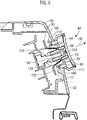
- Cover element 70 comprises a circular front surface 88 which is preferably concavely shaped (see Figs 5 and 6 ).
- carrier element 72 has a circular base portion or flange 90 from which a first part 94 protrudes. From first part 94 a central part 98 and two pins 100, 102 protrude which are arranged on opposite sides of central part 100.
- Part 94 preferably comprises, preferably on opposing sides, hook seats 110, 112 into which hooks 120, 122 of cover element 70 engage (see Figs 5 and 6 ).
- Pins 100, 102 have two functions: to assist the positioning of cover element 70 on carrier element and to reduce clearances. Regarding the positioning function, pins 100, 102 have different diameter and engage with / are received in two holes provided on a backside of cover element 70 which in the mounted position faces the control panel 62. The two holes have corresponding diameters, resulting in the fact that the cover element 70 can only in one prescribed orientation be mounted on carrier element 72, avoiding mistakes regarding the assembly of these two components.
- the pins 100, 102 additionally serve to reduce clearances between cover element 70 and carrier element 72. Since hooks 120, 122 do not eliminate all possible displacements between elements 70 and 72, the pins 100, 102 together with the respective holes in cover element 70 eliminate possible remaining clearances / play between these two components. They determine the distance between these two components 70, 72 when the pins are fully inserted in the respective holes and prevent also lateral respective movements as well as rotational play.
- knob 44 with cover element 70 and carrier element 72 is shown in a mounted position on control panel 62.
- Carrier element 72 is preferably rotatable mounted on a carrier seat element 130.
- the carrier seat element 130 provides an axial stop in direction opposite to axial direction 160. In this position, the knob 44 is fully functional.
- a rotatable pin 142 being part of a selector which is connected to an electronic board of the appliance 2 is received by central opening preferably provided on central part 98 of the carrier element 72 on its side facing control panel 62. Snap hooks 120, 122 of cover element 70 are engaged in hook seats 110, 112 of carrier element 72.
- the encoder of appliance 2 preferably comprises a base connected to the electronic board and a rotatable pin 142, the rotation of which result in a different signal used by the machine control unit to select the program / parameter.
- the hole in central part 98 has in the preferred embodiment shown an asymmetric cross section throughout its depth, corresponding to the cross section of pin 142.
- the opening on the central part 98 can have a circular cross section in a region facing the control board and a asymmetric cross section in a region opposite to control board in such a way that in the first or fully inserted position, pin 142 engages with the asymmetric part and is turned when cover element 70 is turned. In the second extracted position below described, however, pin 142 is located in the circular region of opening 98 in such a way that a rotation of cover element 70 and carrier element 72 does not lead to a rotation of pin 142.
- the cover element 70 and carrier element 72 are fixed with each other both in an axial direction 160 as well as radial direction, i.e. both elements 70, 72 rotate collinearly with each other with the same angular velocity when the cover element 70 is turned by the user.
- the configuration shown in FIG. 5 is a first, fully inserted configuration of knob 44 in which the household appliance 2 is operated.
- knob 44 In FIG. 6 , a second configuration of knob 44 is shown. Both cover element 70 as well as carrier element 72 are translated in axial direction 160 compared to the configuration shown in FIG. 5 .
- the maximal stroke by which carrier element 72 can be moved in axial direction 160 is limited by a, preferably circular, sleeve 166 of control panel 62.
- a second positon of knob 44 is defined in which flange 90 touches sleeve 166 by which further movement in axial direction 166 is blocked. In this position, knob 44 is not functional but prepared for full detachment of the knob gaging snap hooks 120, 122 from seats 110, 112.
- Snap hooks 120, 122 and/or seats 110, 112 are built elastically and can be preferably disengaged one after the other or simultaneously. When both hooks 120, 122 are disengaged, cover element 70 is disengaged from carrier element 72 and can be fully removed.
- knob replacement is therefore performed as follows.
- a first step starting from the configuration shown in FIG. 5 , knob cover element 70 is pulled in axial direction 160 until a mechanical resistance is detected when movement of flange 90 is stopped by sleeve 166. Until this position has reached, cover element 70, which is engaged with carrier element 72, and carrier element 72 move together in axial direction 160.
- cover element 70 When this second position is reached, the aperture 170 between cover element 70 and carrier element 72 is accessible.
- a tool preferably a screwdriver, is inserted into aperture for disengaging hooks 120, 122 from respective hook seats 110, 112. Cover element 70 can now be removed, leaving behind carrier element 72.
- the tool is suitable for this disengagement and is preferably provided with the appliance 2 to the user.
- another cover element 70 is connected to carrier element 72 by engaging hooks 120, 122 of cover element 70 with hook seats 110, 112 of carrier element 72.
- Pins 100, 102 described above engage with corresponding holes in cover element 70 and assure a correct rotational orientation of cover element 70 and carrier element 72 with respect to each other. Also they center elements 70, 72 and reduce clearances and play. Both elements 70, 72 can be pushed towards the control board 62 in a direction opposite to axial direction 160 until the first and fully inserted position is reached in which carrier element 72 is seated on carrier seat element 130.
Landscapes
- Engineering & Computer Science (AREA)
- Textile Engineering (AREA)
- Physics & Mathematics (AREA)
- General Physics & Mathematics (AREA)
- Automation & Control Theory (AREA)
- Mechanical Control Devices (AREA)
- Main Body Construction Of Washing Machines And Laundry Dryers (AREA)
- Detail Structures Of Washing Machines And Dryers (AREA)
Claims (12)
- Haushaltsgerät (2), umfassend eine Steuertafel (62), auf der ein Benutzerschnittstellenelement bereitgestellt ist, das einen Knopf (44) umfasst, der mit einer Wahlvorrichtung assoziiert ist, wobei der Knopf (44) ein Knopfabdeckelement (70) und ein Knopfträgerelement (72) umfasst, wobei das Knopfabdeckelement (70) entfernbar an dem Knopfträgerelement (72) angebracht ist, und wobei das Knopfträgerelement (72) zumindest teilweise hinter der Steuertafel (62) verschiebbar angeordnet ist,
dadurch gekennzeichnet, dass der Knopf (44) teilweise aus der Steuertafel (62) von einer ersten eingesetzten Position zu einer zweiten herausgezogenen Position herausziehbar ist, in der der Knopf (44) in einer nicht betriebsbereiten Position, jedoch axial durch die Tafel (62) für eine vollständige Demontage von dem Gerät (2) gehalten ist, wobei in der zweiten Position der Knopf (44) zumindest teilweise aus der Steuertafel (62) entfernbar ist, wobei das Knopfabdeckelement (70) von dem Knopfträgerelement (72) durch den Benutzer in/nur in der zweiten Position vollständig abnehmbar ist. - Haushaltsgerät (2) nach Anspruch 1, wobei das Knopfabdeckelement (70) und das Knopfträgerelement (72) durch eine Schnappverbindung/Befestigungsmittel aneinander angebracht sind.
- Haushaltsgerät (2) nach Anspruch 2, wobei das Knopfträgerelement (74) mindestens einen Hakensitz (110, 112) umfasst, in den in der angebrachten Auslegung mindestens ein Schnapphaken (120, 122) des Knopfabdeckelements (70) eingreift.
- Haushaltsgerät (2) nach einem der vorhergehenden Ansprüche, wobei das Knopfträgerelement (72) einen äußeren Flansch (90) umfasst, der als ein axialer Block dient, wenn die zweite herausgezogene Position des Knopfes (44) erreicht ist.
- Haushaltsgerät (2) nach Anspruch 4, wobei der Flansch (90) in der zweiten herausgezogenen Position durch ein Blockierungsmittel (166) der Steuertafel (62) blockiert ist.
- Haushaltsgerät (2) nach einem der vorhergehenden Ansprüche, wobei das Knopfträgerelement (72) in Bezug auf die/an der Wahlvorrichtung verschiebbar angeordnet ist.
- Haushaltsgerät (2) nach einem der vorhergehenden Ansprüche, wobei in der montierten Position des Knopfabdeckelements (70) und des Knopfträgerelements (72) zwischen den zwei Elementen (70, 72) ein Durchgang (170) bereitgestellt ist, der ausgelegt ist, das Einsetzen eines Werkzeugs zu ermöglichen, wenn der Knopf (44) an der zweiten herausgezogenen Position angeordnet ist.
- Haushaltsgerät (2) nach einem der vorhergehenden Ansprüche, wobei das Knopfabdeckelement (70) nichtrotierbar an dem Knopfträgerelement (72) angebracht ist.
- Haushaltsgerät (2) nach einem der vorhergehenden Ansprüche, wobei das Knopfträgerelement (72) Mittel umfasst, die mit einem Geber zusammenwirken.
- Haushaltsgerät (2) nach einem der vorhergehenden Ansprüche, wobei das Material des Knopfabdeck- und/oder des Knopfträgerelements A.B.S. (Acrylnitril-Butadien-Styrol) ist.
- Haushaltsgerät (2) nach einem der vorhergehenden Ansprüche, das als eine Wäschebehandlungsmaschine ausgeführt ist.
- Verfahren zum Betreiben eines Haushaltsgeräts (2) nach einem der vorhergehenden Ansprüche, mit den Schritten• Ziehen des Knopfabdeckelements (70) weg von der Steuertafel (62), bis der Knopf (44) die zweite herausgezogene Position erreicht;• Abnehmen des Knopfabdeckelements (70) von dem Knopfträgerelement (72).
Priority Applications (3)
| Application Number | Priority Date | Filing Date | Title |
|---|---|---|---|
| EP17188024.8A EP3447182B1 (de) | 2017-08-25 | 2017-08-25 | Haushaltsgerät und verfahren zum betrieb eines haushaltsgeräts |
| PL17188024T PL3447182T3 (pl) | 2017-08-25 | 2017-08-25 | Urządzenie gospodarstwa domowego i sposób obsługi urządzenia gospodarstwa domowego |
| PCT/EP2018/071078 WO2019038056A1 (en) | 2017-08-25 | 2018-08-02 | ELECTRICAL HOUSEHOLD APPLIANCE AND METHOD FOR OPERATING AN ELECTRIC HOUSEHOLD APPLIANCE |
Applications Claiming Priority (1)
| Application Number | Priority Date | Filing Date | Title |
|---|---|---|---|
| EP17188024.8A EP3447182B1 (de) | 2017-08-25 | 2017-08-25 | Haushaltsgerät und verfahren zum betrieb eines haushaltsgeräts |
Publications (2)
| Publication Number | Publication Date |
|---|---|
| EP3447182A1 EP3447182A1 (de) | 2019-02-27 |
| EP3447182B1 true EP3447182B1 (de) | 2021-08-04 |
Family
ID=59702646
Family Applications (1)
| Application Number | Title | Priority Date | Filing Date |
|---|---|---|---|
| EP17188024.8A Active EP3447182B1 (de) | 2017-08-25 | 2017-08-25 | Haushaltsgerät und verfahren zum betrieb eines haushaltsgeräts |
Country Status (3)
| Country | Link |
|---|---|
| EP (1) | EP3447182B1 (de) |
| PL (1) | PL3447182T3 (de) |
| WO (1) | WO2019038056A1 (de) |
Cited By (1)
| Publication number | Priority date | Publication date | Assignee | Title |
|---|---|---|---|---|
| WO2025037110A1 (en) * | 2023-08-15 | 2025-02-20 | Aqualisa Products Limited | Knob assembly |
Families Citing this family (1)
| Publication number | Priority date | Publication date | Assignee | Title |
|---|---|---|---|---|
| CN112030468A (zh) * | 2020-09-27 | 2020-12-04 | 南京创维家用电器有限公司 | 一种滚筒洗衣机控板旋钮晃动优化结构 |
Family Cites Families (4)
| Publication number | Priority date | Publication date | Assignee | Title |
|---|---|---|---|---|
| DE3803356A1 (de) * | 1988-02-05 | 1989-08-17 | Bauknecht Hausgeraete | Drehknopf fuer steuergeraete o. dgl. |
| DE19951422B4 (de) * | 1999-10-26 | 2006-04-06 | AEG Hausgeräte GmbH | Versenkbare Drehbedieneinheit |
| KR20150120120A (ko) * | 2014-04-17 | 2015-10-27 | 삼성전자주식회사 | 상하운동이 가능한 회전 노브 조립체 |
| WO2017044059A1 (en) * | 2015-09-08 | 2017-03-16 | Arcelik Anonim Sirketi | A household appliance comprising a decorative element that can be attached to/detached from the knob |
-
2017
- 2017-08-25 EP EP17188024.8A patent/EP3447182B1/de active Active
- 2017-08-25 PL PL17188024T patent/PL3447182T3/pl unknown
-
2018
- 2018-08-02 WO PCT/EP2018/071078 patent/WO2019038056A1/en not_active Ceased
Non-Patent Citations (1)
| Title |
|---|
| None * |
Cited By (1)
| Publication number | Priority date | Publication date | Assignee | Title |
|---|---|---|---|---|
| WO2025037110A1 (en) * | 2023-08-15 | 2025-02-20 | Aqualisa Products Limited | Knob assembly |
Also Published As
| Publication number | Publication date |
|---|---|
| WO2019038056A1 (en) | 2019-02-28 |
| PL3447182T3 (pl) | 2022-01-03 |
| EP3447182A1 (de) | 2019-02-27 |
Similar Documents
| Publication | Publication Date | Title |
|---|---|---|
| US10465331B2 (en) | Laundry treatment appliance | |
| EP2602377B1 (de) | Waschmaschine mit einer Knopfanordnung | |
| US7802855B2 (en) | Home appliance having a door | |
| EP3290565B1 (de) | Hausgerät mit einer berührungsanzeigetafel | |
| US8438878B2 (en) | Control unit of laundry processing apparatus | |
| KR20160084073A (ko) | 의류처리장치 및 도어 | |
| US20170242573A1 (en) | Operating mechanism for a household appliance having an operating element and a display area configured in the operating element | |
| EP3447182B1 (de) | Haushaltsgerät und verfahren zum betrieb eines haushaltsgeräts | |
| CA2527758C (en) | Appliance with membrane overlay | |
| EP3450612B1 (de) | Wäschewaschmaschine und verfahren zum auswählen von waschverfahren einer wäschewaschmaschine | |
| EP3516103A1 (de) | Haushaltsgerät mit einem knopf | |
| EP3064633A1 (de) | Wäschebehandlungsvorrichtung mit benutzeroberfläche | |
| US12410918B2 (en) | Operator control device comprising a multi-part operator control element, and domestic appliance and method for operating a domestic appliance | |
| EP1829071A1 (de) | Haushaltsgerät | |
| CN110578234B (zh) | 滚筒洗衣机及其控制面板 | |
| CN107429467B (zh) | 衣物处理器具 | |
| EP2764524B1 (de) | Haushaltsgerät | |
| CN110438744A (zh) | 一种应用于衣物处理设备的操控旋钮及衣物处理设备 | |
| EP4187009B1 (de) | Haushaltsgerät mit einem knopf | |
| KR101706969B1 (ko) | 의류처리장치 및 도어 | |
| WO2017044059A1 (en) | A household appliance comprising a decorative element that can be attached to/detached from the knob | |
| WO2020126468A1 (en) | A household appliance comprising a decorative element which can be attached to/detached from the knob | |
| KR101706968B1 (ko) | 의류처리장치 및 도어 | |
| WO2017194500A2 (en) | A household appliance comprising a knob safely mounted onto the panel | |
| KR101263866B1 (ko) | 컨트롤러의 노브 장치 |
Legal Events
| Date | Code | Title | Description |
|---|---|---|---|
| PUAI | Public reference made under article 153(3) epc to a published international application that has entered the european phase |
Free format text: ORIGINAL CODE: 0009012 |
|
| STAA | Information on the status of an ep patent application or granted ep patent |
Free format text: STATUS: THE APPLICATION HAS BEEN PUBLISHED |
|
| AK | Designated contracting states |
Kind code of ref document: A1 Designated state(s): AL AT BE BG CH CY CZ DE DK EE ES FI FR GB GR HR HU IE IS IT LI LT LU LV MC MK MT NL NO PL PT RO RS SE SI SK SM TR |
|
| AX | Request for extension of the european patent |
Extension state: BA ME |
|
| STAA | Information on the status of an ep patent application or granted ep patent |
Free format text: STATUS: REQUEST FOR EXAMINATION WAS MADE |
|
| 17P | Request for examination filed |
Effective date: 20190827 |
|
| RBV | Designated contracting states (corrected) |
Designated state(s): AL AT BE BG CH CY CZ DE DK EE ES FI FR GB GR HR HU IE IS IT LI LT LU LV MC MK MT NL NO PL PT RO RS SE SI SK SM TR |
|
| STAA | Information on the status of an ep patent application or granted ep patent |
Free format text: STATUS: EXAMINATION IS IN PROGRESS |
|
| 17Q | First examination report despatched |
Effective date: 20200804 |
|
| REG | Reference to a national code |
Ref country code: DE Ref legal event code: R079 Ref document number: 602017043243 Country of ref document: DE Free format text: PREVIOUS MAIN CLASS: D06F0039000000 Ipc: D06F0034300000 |
|
| GRAP | Despatch of communication of intention to grant a patent |
Free format text: ORIGINAL CODE: EPIDOSNIGR1 |
|
| STAA | Information on the status of an ep patent application or granted ep patent |
Free format text: STATUS: GRANT OF PATENT IS INTENDED |
|
| RIC1 | Information provided on ipc code assigned before grant |
Ipc: H01H 3/08 20060101ALI20210226BHEP Ipc: G05G 1/12 20060101ALI20210226BHEP Ipc: D06F 34/30 20200101AFI20210226BHEP Ipc: F24C 7/08 20060101ALN20210226BHEP |
|
| INTG | Intention to grant announced |
Effective date: 20210319 |
|
| RIN1 | Information on inventor provided before grant (corrected) |
Inventor name: BAS, ALBERTO Inventor name: MARCUZ, RODOLFO Inventor name: MORANDINI, STEFANO Inventor name: DE PELLEGRIN, ANDREA |
|
| GRAS | Grant fee paid |
Free format text: ORIGINAL CODE: EPIDOSNIGR3 |
|
| GRAA | (expected) grant |
Free format text: ORIGINAL CODE: 0009210 |
|
| STAA | Information on the status of an ep patent application or granted ep patent |
Free format text: STATUS: THE PATENT HAS BEEN GRANTED |
|
| AK | Designated contracting states |
Kind code of ref document: B1 Designated state(s): AL AT BE BG CH CY CZ DE DK EE ES FI FR GB GR HR HU IE IS IT LI LT LU LV MC MK MT NL NO PL PT RO RS SE SI SK SM TR |
|
| REG | Reference to a national code |
Ref country code: GB Ref legal event code: FG4D |
|
| REG | Reference to a national code |
Ref country code: AT Ref legal event code: REF Ref document number: 1417095 Country of ref document: AT Kind code of ref document: T Effective date: 20210815 |
|
| REG | Reference to a national code |
Ref country code: CH Ref legal event code: EP |
|
| REG | Reference to a national code |
Ref country code: DE Ref legal event code: R096 Ref document number: 602017043243 Country of ref document: DE |
|
| REG | Reference to a national code |
Ref country code: IE Ref legal event code: FG4D |
|
| REG | Reference to a national code |
Ref country code: LT Ref legal event code: MG9D |
|
| REG | Reference to a national code |
Ref country code: NL Ref legal event code: MP Effective date: 20210804 |
|
| REG | Reference to a national code |
Ref country code: AT Ref legal event code: MK05 Ref document number: 1417095 Country of ref document: AT Kind code of ref document: T Effective date: 20210804 |
|
| PG25 | Lapsed in a contracting state [announced via postgrant information from national office to epo] |
Ref country code: SE Free format text: LAPSE BECAUSE OF FAILURE TO SUBMIT A TRANSLATION OF THE DESCRIPTION OR TO PAY THE FEE WITHIN THE PRESCRIBED TIME-LIMIT Effective date: 20210804 Ref country code: RS Free format text: LAPSE BECAUSE OF FAILURE TO SUBMIT A TRANSLATION OF THE DESCRIPTION OR TO PAY THE FEE WITHIN THE PRESCRIBED TIME-LIMIT Effective date: 20210804 Ref country code: LT Free format text: LAPSE BECAUSE OF FAILURE TO SUBMIT A TRANSLATION OF THE DESCRIPTION OR TO PAY THE FEE WITHIN THE PRESCRIBED TIME-LIMIT Effective date: 20210804 Ref country code: BG Free format text: LAPSE BECAUSE OF FAILURE TO SUBMIT A TRANSLATION OF THE DESCRIPTION OR TO PAY THE FEE WITHIN THE PRESCRIBED TIME-LIMIT Effective date: 20211104 Ref country code: AT Free format text: LAPSE BECAUSE OF FAILURE TO SUBMIT A TRANSLATION OF THE DESCRIPTION OR TO PAY THE FEE WITHIN THE PRESCRIBED TIME-LIMIT Effective date: 20210804 Ref country code: NO Free format text: LAPSE BECAUSE OF FAILURE TO SUBMIT A TRANSLATION OF THE DESCRIPTION OR TO PAY THE FEE WITHIN THE PRESCRIBED TIME-LIMIT Effective date: 20211104 Ref country code: PT Free format text: LAPSE BECAUSE OF FAILURE TO SUBMIT A TRANSLATION OF THE DESCRIPTION OR TO PAY THE FEE WITHIN THE PRESCRIBED TIME-LIMIT Effective date: 20211206 Ref country code: HR Free format text: LAPSE BECAUSE OF FAILURE TO SUBMIT A TRANSLATION OF THE DESCRIPTION OR TO PAY THE FEE WITHIN THE PRESCRIBED TIME-LIMIT Effective date: 20210804 Ref country code: ES Free format text: LAPSE BECAUSE OF FAILURE TO SUBMIT A TRANSLATION OF THE DESCRIPTION OR TO PAY THE FEE WITHIN THE PRESCRIBED TIME-LIMIT Effective date: 20210804 Ref country code: FI Free format text: LAPSE BECAUSE OF FAILURE TO SUBMIT A TRANSLATION OF THE DESCRIPTION OR TO PAY THE FEE WITHIN THE PRESCRIBED TIME-LIMIT Effective date: 20210804 |
|
| PG25 | Lapsed in a contracting state [announced via postgrant information from national office to epo] |
Ref country code: LV Free format text: LAPSE BECAUSE OF FAILURE TO SUBMIT A TRANSLATION OF THE DESCRIPTION OR TO PAY THE FEE WITHIN THE PRESCRIBED TIME-LIMIT Effective date: 20210804 Ref country code: GR Free format text: LAPSE BECAUSE OF FAILURE TO SUBMIT A TRANSLATION OF THE DESCRIPTION OR TO PAY THE FEE WITHIN THE PRESCRIBED TIME-LIMIT Effective date: 20211105 |
|
| REG | Reference to a national code |
Ref country code: CH Ref legal event code: PL |
|
| PG25 | Lapsed in a contracting state [announced via postgrant information from national office to epo] |
Ref country code: NL Free format text: LAPSE BECAUSE OF FAILURE TO SUBMIT A TRANSLATION OF THE DESCRIPTION OR TO PAY THE FEE WITHIN THE PRESCRIBED TIME-LIMIT Effective date: 20210804 |
|
| REG | Reference to a national code |
Ref country code: BE Ref legal event code: MM Effective date: 20210831 |
|
| PG25 | Lapsed in a contracting state [announced via postgrant information from national office to epo] |
Ref country code: LI Free format text: LAPSE BECAUSE OF NON-PAYMENT OF DUE FEES Effective date: 20210831 Ref country code: DK Free format text: LAPSE BECAUSE OF FAILURE TO SUBMIT A TRANSLATION OF THE DESCRIPTION OR TO PAY THE FEE WITHIN THE PRESCRIBED TIME-LIMIT Effective date: 20210804 Ref country code: CH Free format text: LAPSE BECAUSE OF NON-PAYMENT OF DUE FEES Effective date: 20210831 |
|
| REG | Reference to a national code |
Ref country code: DE Ref legal event code: R097 Ref document number: 602017043243 Country of ref document: DE |
|
| PG25 | Lapsed in a contracting state [announced via postgrant information from national office to epo] |
Ref country code: SM Free format text: LAPSE BECAUSE OF FAILURE TO SUBMIT A TRANSLATION OF THE DESCRIPTION OR TO PAY THE FEE WITHIN THE PRESCRIBED TIME-LIMIT Effective date: 20210804 Ref country code: SK Free format text: LAPSE BECAUSE OF FAILURE TO SUBMIT A TRANSLATION OF THE DESCRIPTION OR TO PAY THE FEE WITHIN THE PRESCRIBED TIME-LIMIT Effective date: 20210804 Ref country code: RO Free format text: LAPSE BECAUSE OF FAILURE TO SUBMIT A TRANSLATION OF THE DESCRIPTION OR TO PAY THE FEE WITHIN THE PRESCRIBED TIME-LIMIT Effective date: 20210804 Ref country code: MC Free format text: LAPSE BECAUSE OF FAILURE TO SUBMIT A TRANSLATION OF THE DESCRIPTION OR TO PAY THE FEE WITHIN THE PRESCRIBED TIME-LIMIT Effective date: 20210804 Ref country code: LU Free format text: LAPSE BECAUSE OF NON-PAYMENT OF DUE FEES Effective date: 20210825 Ref country code: EE Free format text: LAPSE BECAUSE OF FAILURE TO SUBMIT A TRANSLATION OF THE DESCRIPTION OR TO PAY THE FEE WITHIN THE PRESCRIBED TIME-LIMIT Effective date: 20210804 Ref country code: CZ Free format text: LAPSE BECAUSE OF FAILURE TO SUBMIT A TRANSLATION OF THE DESCRIPTION OR TO PAY THE FEE WITHIN THE PRESCRIBED TIME-LIMIT Effective date: 20210804 Ref country code: AL Free format text: LAPSE BECAUSE OF FAILURE TO SUBMIT A TRANSLATION OF THE DESCRIPTION OR TO PAY THE FEE WITHIN THE PRESCRIBED TIME-LIMIT Effective date: 20210804 |
|
| PLBE | No opposition filed within time limit |
Free format text: ORIGINAL CODE: 0009261 |
|
| STAA | Information on the status of an ep patent application or granted ep patent |
Free format text: STATUS: NO OPPOSITION FILED WITHIN TIME LIMIT |
|
| 26N | No opposition filed |
Effective date: 20220506 |
|
| GBPC | Gb: european patent ceased through non-payment of renewal fee |
Effective date: 20211104 |
|
| PG25 | Lapsed in a contracting state [announced via postgrant information from national office to epo] |
Ref country code: IE Free format text: LAPSE BECAUSE OF NON-PAYMENT OF DUE FEES Effective date: 20210825 Ref country code: BE Free format text: LAPSE BECAUSE OF NON-PAYMENT OF DUE FEES Effective date: 20210831 |
|
| PG25 | Lapsed in a contracting state [announced via postgrant information from national office to epo] |
Ref country code: SI Free format text: LAPSE BECAUSE OF FAILURE TO SUBMIT A TRANSLATION OF THE DESCRIPTION OR TO PAY THE FEE WITHIN THE PRESCRIBED TIME-LIMIT Effective date: 20210804 |
|
| PG25 | Lapsed in a contracting state [announced via postgrant information from national office to epo] |
Ref country code: FR Free format text: LAPSE BECAUSE OF NON-PAYMENT OF DUE FEES Effective date: 20211004 |
|
| PG25 | Lapsed in a contracting state [announced via postgrant information from national office to epo] |
Ref country code: GB Free format text: LAPSE BECAUSE OF NON-PAYMENT OF DUE FEES Effective date: 20211104 |
|
| PG25 | Lapsed in a contracting state [announced via postgrant information from national office to epo] |
Ref country code: CY Free format text: LAPSE BECAUSE OF FAILURE TO SUBMIT A TRANSLATION OF THE DESCRIPTION OR TO PAY THE FEE WITHIN THE PRESCRIBED TIME-LIMIT Effective date: 20210804 |
|
| PG25 | Lapsed in a contracting state [announced via postgrant information from national office to epo] |
Ref country code: HU Free format text: LAPSE BECAUSE OF FAILURE TO SUBMIT A TRANSLATION OF THE DESCRIPTION OR TO PAY THE FEE WITHIN THE PRESCRIBED TIME-LIMIT; INVALID AB INITIO Effective date: 20170825 |
|
| P01 | Opt-out of the competence of the unified patent court (upc) registered |
Effective date: 20230625 |
|
| PG25 | Lapsed in a contracting state [announced via postgrant information from national office to epo] |
Ref country code: MK Free format text: LAPSE BECAUSE OF FAILURE TO SUBMIT A TRANSLATION OF THE DESCRIPTION OR TO PAY THE FEE WITHIN THE PRESCRIBED TIME-LIMIT Effective date: 20210804 |
|
| PG25 | Lapsed in a contracting state [announced via postgrant information from national office to epo] |
Ref country code: TR Free format text: LAPSE BECAUSE OF FAILURE TO SUBMIT A TRANSLATION OF THE DESCRIPTION OR TO PAY THE FEE WITHIN THE PRESCRIBED TIME-LIMIT Effective date: 20210804 |
|
| PG25 | Lapsed in a contracting state [announced via postgrant information from national office to epo] |
Ref country code: MT Free format text: LAPSE BECAUSE OF FAILURE TO SUBMIT A TRANSLATION OF THE DESCRIPTION OR TO PAY THE FEE WITHIN THE PRESCRIBED TIME-LIMIT Effective date: 20210804 |
|
| PGFP | Annual fee paid to national office [announced via postgrant information from national office to epo] |
Ref country code: DE Payment date: 20250827 Year of fee payment: 9 |
|
| PGFP | Annual fee paid to national office [announced via postgrant information from national office to epo] |
Ref country code: PL Payment date: 20250812 Year of fee payment: 9 Ref country code: IT Payment date: 20250825 Year of fee payment: 9 |