EP3447191A1 - Dispositif et procédé pour contrôler le compactage - Google Patents
Dispositif et procédé pour contrôler le compactage Download PDFInfo
- Publication number
- EP3447191A1 EP3447191A1 EP17187838.2A EP17187838A EP3447191A1 EP 3447191 A1 EP3447191 A1 EP 3447191A1 EP 17187838 A EP17187838 A EP 17187838A EP 3447191 A1 EP3447191 A1 EP 3447191A1
- Authority
- EP
- European Patent Office
- Prior art keywords
- compression
- compaction
- road
- machine
- value
- Prior art date
- Legal status (The legal status is an assumption and is not a legal conclusion. Google has not performed a legal analysis and makes no representation as to the accuracy of the status listed.)
- Withdrawn
Links
- 238000005056 compaction Methods 0.000 title claims abstract description 115
- 238000000034 method Methods 0.000 title claims description 40
- 239000002689 soil Substances 0.000 claims abstract description 23
- 238000004364 calculation method Methods 0.000 claims abstract description 14
- 238000007906 compression Methods 0.000 claims description 148
- 230000006835 compression Effects 0.000 claims description 141
- 239000000758 substrate Substances 0.000 claims description 14
- 238000004590 computer program Methods 0.000 claims description 13
- 230000004044 response Effects 0.000 claims description 6
- 230000006399 behavior Effects 0.000 claims description 5
- 238000001816 cooling Methods 0.000 claims description 5
- 230000006870 function Effects 0.000 claims description 4
- 239000000654 additive Substances 0.000 claims description 2
- 230000000996 additive effect Effects 0.000 claims description 2
- 230000000903 blocking effect Effects 0.000 claims description 2
- 238000004088 simulation Methods 0.000 claims description 2
- 230000009849 deactivation Effects 0.000 claims 1
- 239000000463 material Substances 0.000 description 23
- 239000010426 asphalt Substances 0.000 description 15
- 238000010276 construction Methods 0.000 description 8
- 238000004891 communication Methods 0.000 description 6
- 238000013459 approach Methods 0.000 description 5
- 230000001276 controlling effect Effects 0.000 description 5
- 238000005096 rolling process Methods 0.000 description 4
- 230000008569 process Effects 0.000 description 3
- 230000008859 change Effects 0.000 description 2
- 239000011521 glass Substances 0.000 description 2
- 238000005259 measurement Methods 0.000 description 2
- 230000001105 regulatory effect Effects 0.000 description 2
- 239000004576 sand Substances 0.000 description 2
- 239000004575 stone Substances 0.000 description 2
- 239000002351 wastewater Substances 0.000 description 2
- 238000013475 authorization Methods 0.000 description 1
- 230000008901 benefit Effects 0.000 description 1
- 230000005540 biological transmission Effects 0.000 description 1
- 238000011161 development Methods 0.000 description 1
- 230000018109 developmental process Effects 0.000 description 1
- -1 earth Substances 0.000 description 1
- 230000000694 effects Effects 0.000 description 1
- 239000000446 fuel Substances 0.000 description 1
- 238000012986 modification Methods 0.000 description 1
- 230000004048 modification Effects 0.000 description 1
- 230000003287 optical effect Effects 0.000 description 1
- 238000012545 processing Methods 0.000 description 1
- 230000008439 repair process Effects 0.000 description 1
- 239000011435 rock Substances 0.000 description 1
- 239000010865 sewage Substances 0.000 description 1
- 238000012546 transfer Methods 0.000 description 1
Images


Classifications
-
- E—FIXED CONSTRUCTIONS
- E01—CONSTRUCTION OF ROADS, RAILWAYS, OR BRIDGES
- E01C—CONSTRUCTION OF, OR SURFACES FOR, ROADS, SPORTS GROUNDS, OR THE LIKE; MACHINES OR AUXILIARY TOOLS FOR CONSTRUCTION OR REPAIR
- E01C19/00—Machines, tools or auxiliary devices for preparing or distributing paving materials, for working the placed materials, or for forming, consolidating, or finishing the paving
- E01C19/22—Machines, tools or auxiliary devices for preparing or distributing paving materials, for working the placed materials, or for forming, consolidating, or finishing the paving for consolidating or finishing laid-down unset materials
- E01C19/23—Rollers therefor; Such rollers usable also for compacting soil
- E01C19/28—Vibrated rollers or rollers subjected to impacts, e.g. hammering blows
- E01C19/288—Vibrated rollers or rollers subjected to impacts, e.g. hammering blows adapted for monitoring characteristics of the material being compacted, e.g. indicating resonant frequency, measuring degree of compaction, by measuring values, detectable on the roller; using detected values to control operation of the roller, e.g. automatic adjustment of vibration responsive to such measurements
Definitions
- Embodiments of the present invention provide an apparatus and method for compaction control. Further embodiments provide a road or Bodenverdichtungsmaschine with appropriate control.
- the present invention relates to the field of rollers, for example, road rollers for compacting a road or road surface.
- a preferred embodiment of the invention relates to a method for controlling the compression of a material layer to be compacted by a roller, such as earth or asphalt layer.
- road pavers such as asphalt material
- road rollers move one or more road rollers during the labor input in a specified by one or more road pavers area in which asphalt material was applied.
- each area of the road is run over several times by a road roller.
- the road roller drives off the road surface in several tracks, as this is usually wider than the roller drum. After the road roller has run over the road surface in individual lanes for a first time, this then begins with another crossing at the first track already crossed over.
- compaction values of the area to be compacted during rolling are measured and displayed to the driver on a monitor or display.
- compaction values of the area to be compacted during rolling are measured and displayed to the driver on a monitor or display.
- EP 1 985 761 A2 a method for determining a degree of compaction of a surface area of a traffic area to be compacted, a system for carrying out this method and a compacting machine with this system.
- position data of the compacting machine are determined and parameters are measured which are suitable for determining the compaction effect.
- parameters are assigned to previously defined subareas and a current degree of compaction for the subareas is calculated from these parameters. In the case of repeated passage of the partial surfaces, the previously measured parameters are included in the calculation.
- a determination of the degree of compaction is usually carried out at each crossing of the roller on the surface to be compacted by the introduced into the ground or acting in the underground forces are measured by means of a compaction meter. From the measured values, a degree of compaction of the subsurface can then be calculated. Thus, by repeatedly driving over the area to be compacted, a change in the compaction of the subsurface can be determined.
- a measuring system is for example in the EP 3 147 406 A1 described.
- a repeated crossing of the roller over a substrate can also quickly lead to over-compression or even damage to the ground, for example, if this has different substructures or run in supply or disposal lines.
- a substructure for example, various materials such as earth, sand, stone or rock, or even laid wastewater or sewer pipes, manholes or the like, and thus have a compression in this area influence.
- An optimal compaction of the substructure is, for example, reached earlier in such places than at other locations in the substructure no pipes or the like run. Are in the substructure already introduced supply or disposal lines and / or pipes, manholes or the like, so over-compression in these areas can damage them, which can sometimes lead to high repair costs.
- the object of the present invention is to provide a concept for compaction control with increased accuracy.
- Embodiments of the present invention provide a compacting control apparatus for compacting a portion of a subsurface by means of a road or soil compaction machine.
- the device comprises an interface, a calculation unit and a controller.
- Actual compression values namely a first actual compression value for a first portion of the range and a second actual compression value for a second portion of the range, are determined via the interface.
- the calculation unit is configured to compare the first actual compression value with a first target compression value for the first portion to determine a first plan compression value (i.e., a compression value for, for example, a next iteration) for that first range.
- a first plan compression value i.e., a compression value for, for example, a next iteration
- the calculation unit compares a second actual compression value with a second target compression value for the second portion to determine a second plan compression value for that range (again, for example, for the next iteration).
- the control of the compaction control now determines a first machine control parameter based on a first plan compaction value for the road or compaction machine, wherein the compaction of the first section takes place or should take place as a function of the first machine control parameter.
- a second machine control parameter for the road or soil compaction machine is determined, starting from which the compaction of the second section takes place or is to take place.
- the compression takes place in several iterations, so that the first and the second section are run over several times.
- first Crossing first iteration
- the first and second actual compression value for a first and second area is determined.
- this first and second actual compression value can then be temporarily stored, so that then, during and before the second iteration, the first and second actual compression values from the first iteration are compared with the first and second desired compression values for the first and second sections and then obtain the first and second plan compression values for the second iteration.
- the corresponding plan compression values for the third iteration e.g. By adjusting the plan compression values from the second iteration.
- Embodiments of the present invention are therefore based on the finding that a size which can be used to control or regulate the compression in the relevant section can be determined by adjusting the actual compression values in relation to the target compression values in sections.
- the compaction power of the machine for example, vibration frequency and / or amplitude
- a crossing speed can be regulated.
- the advantage of this approach is that even before another crossing over an already pre-compressed area, the compression capacity can be reduced and thus any over-compaction of the subsurface is avoided. In other words, this means that in comparison to the prior art, the compression capacity can be regulated back before another crossing in order to avoid a possible error (over-compression).
- the above-described concept also reduces the wear of the machine (eg the road / ground compressor or the roller) as well as the fuel consumption, since the compaction power introduced into the material is adjusted taking into account the precompression on the basis of the already specified compaction values of the ground ,
- a position value is assigned to each actual compression value, target compression value and plan compression value.
- the device may comprise a position sensor which is designed to associate a position value with the actual compression value and / or the plan compression value.
- the sections of the area may comprise a continuous or a varying lateral extent, so that, depending on requirements, a finely divellable subdivision of the area to be compacted is also possible.
- the device may include a compression degree sensor which, in a previous iteration, determines the actual compression to allow the plan compression value for the current iteration to be calculated by the comparison discussed above.
- the device may comprise a radio interface which receives, for example, from another road or ground compressor an actual compression value via a sensor arranged there.
- This variant is particularly advantageous if the compression is to take place with a plurality of road / ground compressors driving one behind the other, so that the downstream road compressor (corresponding to the second iteration or the second compression) its compression power starting from the current / measured actual compression for the still overrunning area, wherein the actual compression value is determined by the preceding compacting machine.
- an actual temperature value which is determined, for example, together with the actual compression value, can also be taken into account.
- a so-called simulation of the cooling behavior with the input parameters of the actual temperature values for the respective area can be used.
- this road compaction machine is configured to provide the compaction power (eg, the amplitude or frequency of a vibrating bandage) in response to the first and second machine control parameters to adapt or to choose.
- the compaction power eg, the amplitude or frequency of a vibrating bandage
- the compression power can be varied in sections, ie, so that the first section is compressed with a different additive compression than the second section. This can also reduce the power to zero.
- the speed of movement of the road compaction machine can be adapted in accordance with embodiments according to the first and second machine control parameters.
- a further embodiment relates to a method for compression control comprising the steps of receiving the actual compression values, comparing the actual compression values with the target compression values for the respective sections, and determining at least the first and second engine control parameters based on the plan compression values.
- the method can be carried out computer-implemented according to further embodiments, i. H.
- a computer program with a program code for carrying out the method is created.
- Fig. 1 Fig. a shows a device 1 for compaction control of a region 21 of a subsurface.
- the area 21 is in Fig. 1b and here comprises a first section A1 and a second section A2.
- the area 21 of the ground may be, for example, a road or a ground that is connected to a road or soil compaction machine, such. B. a roll to be compacted.
- a desired target compression is known.
- the target compression for the first region A1 is stored as the first target compression value
- the target compression for the second region A2 is stored as the second target compression value.
- the two target compression values may be the same or different.
- Reasons for different Zielverdichtitch are, for example, that in the subsurface additional elements such as pipes are provided.
- the device 1 comprises, for example, an interface 1S for receiving current compression values, such. B. measured compression values for the areas A1 and A2, a calculation unit 1 B and a controller 1C.
- the interface 1S receives actual compression values for the sections A1 and A2, ie at least the first and second actual compression values. It should be noted here that the subdivision of the area 21 into any number of sections is possible so that further compression values can also be received via the interface 1S.
- the first and second actual compression values are made available to the downstream calculation unit 1B.
- the calculation unit 1 B receives externally, z. B. from a planning office with the aid of a radio interface, the corresponding target compression values, ie, the first target compression value for a first section A1 and the second target compression value for the second section A2. Other target compression values can of course also be obtained depending on the subdivision of the area 21.
- the authorization unit now compares the obtained actual compression values with the target compression values for the respective sections, in sections So-called plan compression values, ie to obtain a first plan compression value for the section A1 and a second plan compression value for the section A2.
- the control of the road or soil compaction machine is now carried out by means of a controller 1C, which may also be part of the road or soil compaction machine (not shown), for example.
- the control determines, based on the plan compression values, the respective machine control parameters, as a function of which the compression of sections A1 and A2 is to take place.
- the assignment of a first machine control parameter to the section A1 and a second machine control parameter to the section A2 continues.
- These machine control parameters can, for example, influence the compaction performance, for example by adjusting the frequency and / or amplitude of the vibrations as a function of the machine control parameter.
- a machine control parameter may be used to regulate a speed of travel of the individual sections A1 and A2.
- the compaction of the lining 21 with the sections A1 and A2 generally takes place in a plurality of iterations. Furthermore, it is also frequently the case that the device 1 is arranged on a road / soil compaction machine, so that the sensor for determining the actual compaction values is also arranged on the same machine. This has the consequence that, when measuring the first actual compression value, the compression of the section A1 already takes place by means of a predetermined compression rate or speed. The same applies to the compression of section A2.
- the background to this is, in addition to the arrangement, also the measurement principle frequently used in the compaction measurement, according to which the frequency response of the background in section A1 or A2 is evaluated for the introduced vibration energy.
- the actual compression values for the sections A1 and A2 obtained in the first iteration are used to calculate the plan compression values for the respective sections A1 / A2, starting from which the compression power is adjusted in the second iteration.
- the compression capacity can vary from section to section, so that, for example, the still required compression at section A1 is smaller than the compression still required than at section A2.
- the actual compression values by means of another machine eg. B. another compaction machine are determined and then transmitted to the compaction machine with the device 1 by radio, so that the device 1 determines the first direct crossing the plan compression values from the obtained actual compression values.
- the data obtained during the first crossing according to step (d) are transferable to other rollers (either directly by radio connection or indirectly by "storage” on a server), As in road construction usually several rollers are in use (so-called. Roll Association). On the basis of this data, other rollers can adjust the compaction power of the machine from a further passage (from the second crossing) over an already precompressed section accordingly.
- the driving speed can also be adjusted.
- the speed of the roller also influences the compaction of the ground.
- a constant travel speed of the roller is aimed at for an optimum and homogeneously compacted surface.
- the roller should go faster or slower to damage the To avoid subsurface.
- bridges which usually have a concrete surface as a base.
- it is particularly important that the bridge structure after rolling of the asphalt has no damage due to the vibration of the roller drum.
- a roller 10 with a vibrating bandage 12 and a non-vibrating bandage 13 is shown on a substrate 20.
- the bandage 12 corresponding vibrations 25 are introduced into the substrate 20, that is, the substrate 20 is additionally compressed by the bandage 12.
- a position determining system 30 (GNSS / GPS) is arranged on the roof of the roller 10.
- the positioning system 30 receives satellite signals 65 from a satellite system 60 which is in Fig. 1 is represented by three satellites 61 to 63. On the basis of the satellite signals 65, the exact position of the roller 10 can be determined continuously.
- LPR Local Positioning Radar
- a base station transmits signals received from transponders located in known locations in space
- a geodetic positioning system consisting of a total station (tachymeter) and one on the roller arranged prism (retroreflective triple prism or triple mirror), or other known positioning systems used in the field of construction machinery.
- a combination of different positioning systems is conceivable, for example, a combination of a satellite-based and a geodetic positioning system in the area of bridges or underpasses, since there the satellite reception is poor or not available.
- the roller 10 further comprises a device for controlling the compaction performance and a measuring system for determining a compaction value of the material layer 20 (both not shown).
- the roller 10 moves during the compression process in the direction of travel F over a surface 21 of the substrate 20.
- the compacting surface 21 and the substrate to be compacted 20 is divided into four different sections A to D, the nature of the substrate in each of the four sections A to D is different.
- the section A directly below the roller 10 made of earth or gravel
- the lower portion of the substrate 20 consists of one or more stone layers 27.
- a pipe 28 is laid in the substrate 20, for example a sewer pipe.
- the substrate 20 consists of earth and sand.
- the ground 20 in the four sections A to D is compressed to different degrees during the passage with a roller, ie, after the first crossing of the roller no uniform and homogeneous compression occurs.
- Fig. 2b shows a plan view of the area to be compacted 21 Fig. 2a ie with a view from above.
- the roller 10 is located in a section A1 and moves in the direction of travel F in the subsequent section B1 on the first track 1.
- the individual sections and tracks are indicated by dashed lines 40 and 41.
- the roller 10 In order to sufficiently compact the surface 21, the roller 10 repeatedly passes over the surface 21 in a plurality of webs 1 to 3.
- the texture of the ground is different in each of the four sections A to D. However, this is not readily apparent to the roller driver. For example, he will not be able to see the wastewater pipe 28 running in the ground transversely to the direction of travel F of the roll 10 in section C.
- the method provides that first, ie at the beginning or when entering a section A1... D3 of the material layer 20 to be compacted, position data of the roller 10 are determined.
- the roller 10 passes over each section A1... D3 in the first pass with a first compaction power and it is measured by means of the measuring system in each section A1 ... D3 determined at least one compression value of the material layer 20 during the compression process.
- the position data are stored together with the compaction values.
- the compaction power of the roller 10 is adjusted from the device for controlling the compaction performance based on the stored position and compaction values to a predetermined and to be reached Endverdichtungswert.
- the vibration frequency and / or the amplitude of the vibration of the vibrating drum bandage 12 can be reduced if the corresponding section has already been sufficiently compacted or if a further pass of the roller 10 with an unchanged compaction power would lead to overcompaction of the corresponding section.
- a temperature sensor 14 it may be arranged on the roller 10, a temperature sensor 14.
- temperature data can be included with each crossing and, for example, a cooling behavior of the asphalt material can be calculated, which is included in the calculation of the compaction performance of the roller to be set.
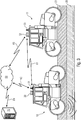
- Fig. 3 shows two rollers 10 and 11, which drive over a surface to be compacted 21 while compacting the substrate 20.
- a roll dressing is used for example in road construction, since the applied asphalt material cools down very quickly and the surface can not be compacted quickly enough with a roller.
- the determined data such as positions and compaction values
- the rollers 10 and 11 are exchanged between the rollers 10 and 11 via communication units (not shown) arranged on the rollers and antennas 31 and 33 via a communication connection 81.
- all recorded and calculated data such as positions and compression values, can be logged on the server 70 in order to subsequently evaluate the performed compaction work.
- rollers are still in use at the construction site, it would also be conceivable to exchange data via a server 70 with which the individual rollers communicate via a network 50.
- communication links 82 and 83 are established between the rollers 10 and 11 and the network 50, the server 70 being connected to the network 50 via a connection 84.
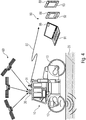
- Fig. 4 shows that the determined data such as positions and compression values can also be transmitted to a mobile device 90 via the communication unit (not shown) arranged on the roller 10 and the antennas 31 via a communication connection 85.
- a mobile device 90 may be, for example, a laptop 91, a smartphone 92 or a tablet PC 93.
- a smartwatch or a data glasses or the like can receive the signals emitted by the antenna 31 signals 85.
- Each of the mobile devices 90 has a corresponding interface 88 for receiving the data.
- An installed and executable on said mobile devices 90 software is able to display based on the received data, for example, the compaction values of the substrate or machine parameters of the roller graphically on a display of the mobile device or in the data glasses d. H. to visualize for the driver of the roller or also for the construction site personnel working on the construction site or in a construction site office. Also, all recorded and calculated data, such as positions and compression values, may be logged on the mobile terminal 90, i. H. be stored in order to be able to subsequently evaluate the compaction work carried out.
- a software installed and executable on the server 70 or on the mobile terminal 90 can perform a classification of the rollers on the basis of the data which were determined on the first passage of one or more rollers over the road surface.
- a software installed and executable on the server 70 or on the mobile terminal 90 can perform a classification of the rollers on the basis of the data which were determined on the first passage of one or more rollers over the road surface.
- heavy rollers are used with a greater compaction performance and in places or in sections where only slightly or no longer needs to be compressed, only smaller or lighter rollers are used.
- a division of sections may also be used to prohibit further driving over certain sections / areas, ie. H. Zones are defined in which the rollers are not allowed to retract.
- the software installed and executable on the server 70 or on the mobile terminal 90 performs calculations for this purpose and transmits the corresponding data to the individual rollers, so that there is, for example, a corresponding message or a message / alarm on an on-board computer for the driver of the roller.
- the above-mentioned server 70 it is possible to use the above-mentioned server 70 not only to exchange data of the actual compression data, but also to Logging purposes. In this case, preferably all recorded calculated data are logged in order to be able to subsequently prove and evaluate the compaction work that has been carried out.
- the adjustment of the compaction performance takes place in such a way that, in addition to the machine control parameter, a selection of the machine type also takes place for a further iteration.
- different machines can perform different compaction work, for example due to different impressed performances or different weights. For example, assuming that in the first iteration a very heavy compaction machine is compacted and the actual compaction values are taken, a different machine may be used for the second iteration where appropriate machine control parameters are adjusted.
- a possible scenario would therefore be that a heavy compaction roller is used at points or paths where a large compaction is necessary, while in other places where only slightly compacted, a lighter compaction roller is used.
- individual sections do not have to be compressed at all, so that these sections or even whole zones are blocked for further passage, so that individual sections are provided with a blocking instruction, so that the rollers no longer retract here allowed.
- the compression or the individual compaction performance often depends on a surface temperature or a material temperature of the material to be incorporated, such. B. from the street to be installed. Therefore, according to embodiments temperature sensors may be provided, the z. B. are connected via the above-explained interface 1 S with the device 1 to the temperature, for. B. on the roller to monitor the asphalt compaction.
- the temperature data is recorded and a cooling behavior is calculated, which is included in the calculation of the compaction power of the roller to be set.
- a compression capacity must be reduced more or less. Note: After the first crossing of a roller over a freshly applied asphalt layer, its surface becomes Smoothed, so that the cooling behavior of the asphalt changed by the changed heat transfer between asphalt and the environment.
- aspects have been described in the context of a device, it will be understood that these aspects also constitute a description of the corresponding method, so that a block or a component of a device is also to be understood as a corresponding method step or as a feature of a method step. Similarly, aspects described in connection with or as a method step also represent a description of a corresponding block or detail or feature of a corresponding device.
- Some or all of the method steps may be performed by a hardware device (or using a hardware device). Apparatus), such as a microprocessor, a programmable computer or an electronic circuit. In some embodiments, some or more of the most important method steps may be performed by such an apparatus.
- embodiments of the invention may be implemented in hardware or in software.
- the implementation may be performed using a digital storage medium, such as a floppy disk, a DVD, a Blu-ray Disc, a CD, a ROM, a PROM, an EPROM, an EEPROM or FLASH memory, a hard disk, or other magnetic disk or optical memory are stored on the electronically readable control signals that can cooperate with a programmable computer system or cooperate such that the respective method is performed. Therefore, the digital storage medium can be computer readable.
- some embodiments according to the invention include a data carrier having electronically readable control signals capable of interacting with a programmable computer system such that one of the methods described herein is performed.
- embodiments of the present invention may be implemented as a computer program product having a program code, wherein the program code is operable to perform one of the methods when the computer program product runs on a computer.
- the program code can also be stored, for example, on a machine-readable carrier.
- inventions include the computer program for performing any of the methods described herein, wherein the computer program is stored on a machine-readable medium.
- an embodiment of the method according to the invention is thus a computer program which has a program code for performing one of the methods described herein when the computer program runs on a computer.
- a further embodiment of the inventive method is thus a data carrier (or a digital storage medium or a computer-readable medium) on which the computer program is recorded for carrying out one of the methods described herein.
- a further embodiment of the method according to the invention is thus a data stream or a sequence of signals, which represent the computer program for performing one of the methods described herein.
- the data stream or the sequence of signals may be configured, for example, to be transferred via a data communication connection, for example via the Internet.
- Another embodiment includes a processing device, such as a computer or a programmable logic device, that is configured or adapted to perform one of the methods described herein.
- a processing device such as a computer or a programmable logic device, that is configured or adapted to perform one of the methods described herein.
- Another embodiment includes a computer on which the computer program is installed to perform one of the methods described herein.
- Another embodiment according to the invention comprises a device or system adapted to transmit a computer program for performing at least one of the methods described herein to a receiver.
- the transmission can be done for example electronically or optically.
- the receiver may be, for example, a computer, a mobile device, a storage device or a similar device.
- the device or system may include a file server for transmitting the computer program to the recipient.
- a programmable logic device eg, a field programmable gate array, an FPGA
- a field programmable gate array may cooperate with a microprocessor to perform one of the methods described herein.
- the methods are performed by any hardware device. This may be a universal hardware such as a computer processor (CPU) or hardware specific to the process, such as an ASIC.
Landscapes
- Engineering & Computer Science (AREA)
- Architecture (AREA)
- Civil Engineering (AREA)
- Structural Engineering (AREA)
- Road Paving Machines (AREA)
Priority Applications (1)
| Application Number | Priority Date | Filing Date | Title |
|---|---|---|---|
| EP17187838.2A EP3447191A1 (fr) | 2017-08-24 | 2017-08-24 | Dispositif et procédé pour contrôler le compactage |
Applications Claiming Priority (1)
| Application Number | Priority Date | Filing Date | Title |
|---|---|---|---|
| EP17187838.2A EP3447191A1 (fr) | 2017-08-24 | 2017-08-24 | Dispositif et procédé pour contrôler le compactage |
Publications (1)
| Publication Number | Publication Date |
|---|---|
| EP3447191A1 true EP3447191A1 (fr) | 2019-02-27 |
Family
ID=59699631
Family Applications (1)
| Application Number | Title | Priority Date | Filing Date |
|---|---|---|---|
| EP17187838.2A Withdrawn EP3447191A1 (fr) | 2017-08-24 | 2017-08-24 | Dispositif et procédé pour contrôler le compactage |
Country Status (1)
| Country | Link |
|---|---|
| EP (1) | EP3447191A1 (fr) |
Cited By (4)
| Publication number | Priority date | Publication date | Assignee | Title |
|---|---|---|---|---|
| EP4332302A1 (fr) | 2022-08-29 | 2024-03-06 | MOBA Mobile Automation AG | Compresseur |
| CN117830972A (zh) * | 2024-01-05 | 2024-04-05 | 青岛科泰重工机械有限公司 | 一种全液压双钢轮压路机远程控制系统及其控制方法 |
| CN119590151A (zh) * | 2025-01-17 | 2025-03-11 | 东北农业大学 | 面向土壤压实消减的拖拉机胎压调节方法和系统 |
| US12577749B2 (en) | 2022-01-10 | 2026-03-17 | Caterpillar Paving Products Inc. | Compaction-based dynamic automated compaction plan |
Citations (6)
| Publication number | Priority date | Publication date | Assignee | Title |
|---|---|---|---|---|
| DE69434631T2 (de) | 1993-04-29 | 2006-08-03 | Geodynamik Ht Ab | Verfahren und Vorrichtung zum Messen des Verdichtungsgrads einer Bodenfläche |
| US20070150147A1 (en) * | 2005-12-23 | 2007-06-28 | Rasmussen Terry L | Compactor using compaction value targets |
| EP1985761A2 (fr) | 2007-04-23 | 2008-10-29 | Hamm AG | Procédé pour la détermination du degré de compaction d'asphalte et dispositif compacteur ainsi que système de détermination d'un degré de compaction |
| DE202009008592U1 (de) | 2009-06-19 | 2009-09-03 | Völkel Mikroelektronik GmbH | Elektronische Einrichtung zum Messen und Anzeigen der Homogenität und des Verdichtungsgrades bei Bodenverdichtern |
| US20160076205A1 (en) * | 2014-09-16 | 2016-03-17 | Caterpillar Paving Products Inc. | Device and Process for Controlling Compaction Based on Previously Mapped Data |
| EP3147406A1 (fr) | 2015-09-25 | 2017-03-29 | MOBA Mobile Automation AG | Système de mesure et procédé destinés au contrôle de compression d'un revêtement et programme d'ordinateur avec un code de programme pour exécuter la procédure |
-
2017
- 2017-08-24 EP EP17187838.2A patent/EP3447191A1/fr not_active Withdrawn
Patent Citations (6)
| Publication number | Priority date | Publication date | Assignee | Title |
|---|---|---|---|---|
| DE69434631T2 (de) | 1993-04-29 | 2006-08-03 | Geodynamik Ht Ab | Verfahren und Vorrichtung zum Messen des Verdichtungsgrads einer Bodenfläche |
| US20070150147A1 (en) * | 2005-12-23 | 2007-06-28 | Rasmussen Terry L | Compactor using compaction value targets |
| EP1985761A2 (fr) | 2007-04-23 | 2008-10-29 | Hamm AG | Procédé pour la détermination du degré de compaction d'asphalte et dispositif compacteur ainsi que système de détermination d'un degré de compaction |
| DE202009008592U1 (de) | 2009-06-19 | 2009-09-03 | Völkel Mikroelektronik GmbH | Elektronische Einrichtung zum Messen und Anzeigen der Homogenität und des Verdichtungsgrades bei Bodenverdichtern |
| US20160076205A1 (en) * | 2014-09-16 | 2016-03-17 | Caterpillar Paving Products Inc. | Device and Process for Controlling Compaction Based on Previously Mapped Data |
| EP3147406A1 (fr) | 2015-09-25 | 2017-03-29 | MOBA Mobile Automation AG | Système de mesure et procédé destinés au contrôle de compression d'un revêtement et programme d'ordinateur avec un code de programme pour exécuter la procédure |
Cited By (5)
| Publication number | Priority date | Publication date | Assignee | Title |
|---|---|---|---|---|
| US12577749B2 (en) | 2022-01-10 | 2026-03-17 | Caterpillar Paving Products Inc. | Compaction-based dynamic automated compaction plan |
| EP4332302A1 (fr) | 2022-08-29 | 2024-03-06 | MOBA Mobile Automation AG | Compresseur |
| CN117830972A (zh) * | 2024-01-05 | 2024-04-05 | 青岛科泰重工机械有限公司 | 一种全液压双钢轮压路机远程控制系统及其控制方法 |
| CN117830972B (zh) * | 2024-01-05 | 2024-05-31 | 青岛科泰重工机械有限公司 | 一种全液压双钢轮压路机远程控制系统及其控制方法 |
| CN119590151A (zh) * | 2025-01-17 | 2025-03-11 | 东北农业大学 | 面向土壤压实消减的拖拉机胎压调节方法和系统 |
Similar Documents
| Publication | Publication Date | Title |
|---|---|---|
| EP2514871B1 (fr) | Procédé pour la pose et le compactage d'une couche d'asphalte | |
| EP1861546B1 (fr) | Systeme permettant de traiter un sol de maniere coordonnee | |
| EP3406799B1 (fr) | Train de machines composé d'une fraiseuse routière et d'une finisseuse de route et procédé de fonctionnement d'une fraiseuse routière et d'une finisseuse de route | |
| EP2852707B1 (fr) | Procédé de planification et de mise en oeuvre de procédures de compactage du sol, en particulier de compactage d'asphalte | |
| EP3480362B1 (fr) | Rouleau dameur et procédé de détermination de l'épaisseur de couche | |
| EP2366830B1 (fr) | Système et procédé d'application d'un revêtement routier | |
| DE112009001610T5 (de) | Pflastersystem und Pflasterverfahren | |
| DE102016124875A1 (de) | Verdichtungsmessung unter Verwendung von nahegelegenen Sensoren | |
| DE102019121492A1 (de) | System und verfahren zum steuern von autonomen baufahrzeugen | |
| DE102018132113A1 (de) | System und Verfahren zum Verdichten einer Oberfläche einer Arbeitsstelle | |
| DE102017008602A1 (de) | Verfahren zur Überwachung des Verdichtungsprozesses im Straßenbau und Straßenwalze | |
| EP1118713B1 (fr) | Procédé de commande d'une machine de chantier ou finisseuse et finisseuse | |
| EP3447191A1 (fr) | Dispositif et procédé pour contrôler le compactage | |
| EP3147406B1 (fr) | Système de mesure et procédé destinés au contrôle de compression d'un revêtement et programme d'ordinateur avec un code de programme pour exécuter la procédure | |
| EP3851584B1 (fr) | Finisseuse de route pourvue de commande de compression | |
| DE10317160A1 (de) | System und Verfahren zur automatisierten Bodenverdichtung | |
| DE102008058481A1 (de) | Asphaltierungssystem und Asphaltierungsverfahren | |
| DE102007019419A1 (de) | Verfahren zur Bestimmung eines Verdichtungsgrades von Asphalten sowie System zur Bestimmung eines Verdichtungsgrades | |
| DE112015003743T5 (de) | Vorrichtung und Verfahren zum Steuern der Verdichtung auf der Grundlage zuvor kartierter Daten | |
| EP4056758A1 (fr) | Procédé de fabrication d'un revêtement routier et système d'asphaltage | |
| DE102019125045A1 (de) | Baustellenplanung für autonome baufahrzeuge | |
| EP3835485A1 (fr) | Système de mesure pour une machine de construction | |
| EP4097418A1 (fr) | Système de mesure et système de commande | |
| DE102022115469A1 (de) | System und verfahren zur markierung einer begrenzung während der definition eines autonomen arbeitsbereichs | |
| DE102022134941A1 (de) | Verdichtungsbasierter dynamischer automatischer verdichtungsplan |
Legal Events
| Date | Code | Title | Description |
|---|---|---|---|
| PUAI | Public reference made under article 153(3) epc to a published international application that has entered the european phase |
Free format text: ORIGINAL CODE: 0009012 |
|
| AK | Designated contracting states |
Kind code of ref document: A1 Designated state(s): AL AT BE BG CH CY CZ DE DK EE ES FI FR GB GR HR HU IE IS IT LI LT LU LV MC MK MT NL NO PL PT RO RS SE SI SK SM TR |
|
| AX | Request for extension of the european patent |
Extension state: BA ME |
|
| STAA | Information on the status of an ep patent application or granted ep patent |
Free format text: STATUS: THE APPLICATION IS DEEMED TO BE WITHDRAWN |
|
| 18D | Application deemed to be withdrawn |
Effective date: 20190828 |