EP3447223A1 - Bandteil eines scharnierbandes - Google Patents
Bandteil eines scharnierbandes Download PDFInfo
- Publication number
- EP3447223A1 EP3447223A1 EP18194436.4A EP18194436A EP3447223A1 EP 3447223 A1 EP3447223 A1 EP 3447223A1 EP 18194436 A EP18194436 A EP 18194436A EP 3447223 A1 EP3447223 A1 EP 3447223A1
- Authority
- EP
- European Patent Office
- Prior art keywords
- mounting
- extension
- wall
- pass
- part according
- Prior art date
- Legal status (The legal status is an assumption and is not a legal conclusion. Google has not performed a legal analysis and makes no representation as to the accuracy of the status listed.)
- Granted
Links
Images



Classifications
-
- E—FIXED CONSTRUCTIONS
- E05—LOCKS; KEYS; WINDOW OR DOOR FITTINGS; SAFES
- E05D—HINGES OR SUSPENSION DEVICES FOR DOORS, WINDOWS OR WINGS
- E05D5/00—Construction of single parts, e.g. the parts for attachment
- E05D5/02—Parts for attachment, e.g. flaps
- E05D5/0215—Parts for attachment, e.g. flaps for attachment to profile members or the like
- E05D5/0223—Parts for attachment, e.g. flaps for attachment to profile members or the like with parts, e.g. screws, extending through the profile wall or engaging profile grooves
- E05D5/023—Parts for attachment, e.g. flaps for attachment to profile members or the like with parts, e.g. screws, extending through the profile wall or engaging profile grooves with parts extending through the profile wall
-
- E—FIXED CONSTRUCTIONS
- E05—LOCKS; KEYS; WINDOW OR DOOR FITTINGS; SAFES
- E05D—HINGES OR SUSPENSION DEVICES FOR DOORS, WINDOWS OR WINGS
- E05D7/00—Hinges or pivots of special construction
- E05D7/04—Hinges adjustable relative to the wing or the frame
- E05D7/0415—Hinges adjustable relative to the wing or the frame with adjusting drive means
- E05D7/0423—Screw-and-nut mechanisms
-
- E—FIXED CONSTRUCTIONS
- E05—LOCKS; KEYS; WINDOW OR DOOR FITTINGS; SAFES
- E05D—HINGES OR SUSPENSION DEVICES FOR DOORS, WINDOWS OR WINGS
- E05D7/00—Hinges or pivots of special construction
- E05D7/04—Hinges adjustable relative to the wing or the frame
- E05D2007/0484—Hinges adjustable relative to the wing or the frame in a radial direction
-
- E—FIXED CONSTRUCTIONS
- E05—LOCKS; KEYS; WINDOW OR DOOR FITTINGS; SAFES
- E05Y—INDEXING SCHEME ASSOCIATED WITH SUBCLASSES E05D AND E05F, RELATING TO CONSTRUCTION ELEMENTS, ELECTRIC CONTROL, POWER SUPPLY, POWER SIGNAL OR TRANSMISSION, USER INTERFACES, MOUNTING OR COUPLING, DETAILS, ACCESSORIES, AUXILIARY OPERATIONS NOT OTHERWISE PROVIDED FOR, APPLICATION THEREOF
- E05Y2600/00—Mounting or coupling arrangements for elements provided for in this subclass
- E05Y2600/50—Mounting methods; Positioning
- E05Y2600/56—Positioning, e.g. re-positioning, or pre-mounting
-
- E—FIXED CONSTRUCTIONS
- E05—LOCKS; KEYS; WINDOW OR DOOR FITTINGS; SAFES
- E05Y—INDEXING SCHEME ASSOCIATED WITH SUBCLASSES E05D AND E05F, RELATING TO CONSTRUCTION ELEMENTS, ELECTRIC CONTROL, POWER SUPPLY, POWER SIGNAL OR TRANSMISSION, USER INTERFACES, MOUNTING OR COUPLING, DETAILS, ACCESSORIES, AUXILIARY OPERATIONS NOT OTHERWISE PROVIDED FOR, APPLICATION THEREOF
- E05Y2600/00—Mounting or coupling arrangements for elements provided for in this subclass
- E05Y2600/60—Mounting or coupling members; Accessories therefor
- E05Y2600/622—Dowels; Pins
-
- E—FIXED CONSTRUCTIONS
- E05—LOCKS; KEYS; WINDOW OR DOOR FITTINGS; SAFES
- E05Y—INDEXING SCHEME ASSOCIATED WITH SUBCLASSES E05D AND E05F, RELATING TO CONSTRUCTION ELEMENTS, ELECTRIC CONTROL, POWER SUPPLY, POWER SIGNAL OR TRANSMISSION, USER INTERFACES, MOUNTING OR COUPLING, DETAILS, ACCESSORIES, AUXILIARY OPERATIONS NOT OTHERWISE PROVIDED FOR, APPLICATION THEREOF
- E05Y2900/00—Application of doors, windows, wings or fittings thereof
- E05Y2900/10—Application of doors, windows, wings or fittings thereof for buildings or parts thereof
- E05Y2900/13—Type of wing
- E05Y2900/132—Doors
Definitions
- the invention relates to a hinge part of a hinge for attachment to a mounting wall of a multi-chamber hollow profile, in particular a wing hinge part, wherein the hinge part comprises a fixed attachable to the multi-chamber hollow profile mounting member and a displaceable relative to the mounting member and fixable in a desired displacement position adjusting part.
- Such a band part is for example from the EP 1 106 763 B1 known.
- the attachment of the mounting part to the mounting wall is carried out by means of six screws that pass through the mounting part in designated holes.
- the hollow chamber profiles regularly consist of multi-chamber profiles, in which usually several insulating chambers are integrated. So that the glazing meets the high requirements for thermal insulation, at least triple glazing is regularly provided. Due to the weight gain caused thereby, in particular plastic profiles on metal reinforcements, so that these profiles can also accommodate the high weights without considerable deformation of the profile. So that the weight of the metal reinforcement by the already heavy plastic profiles as low as possible is kept, the wall thicknesses of the partitions between the individual profile chambers are dimensioned small.
- the invention is therefore based on the object to provide a band part of the type mentioned, which is better suited for attachment to multi-chamber hollow sections.
- the mounting part comprises at least a first pass extension, which is provided for at least almost play-free engagement in holes in the mounting wall and in the inner wall, and at least a second pass extension, which is provided for at least almost play-free engagement in holes only the mounting wall.
- expansion dowel-like is meant that measures are provided with which the outer diameter of the fitting extension is at least over a part of its length enlargeable so as to be able to press its outer periphery against the edges of the holes in the mounting wall and the inner wall.
- a spreading pin which can be driven into an internal volume of the expansion dowel-type pass-extension or, preferably, a screw-in expansion screw, is used for spreading.
- This embodiment is particularly suitable for a one-time, permanent attachment of the mounting part to the multi-chamber hollow profile, since it is simple and inexpensive to produce, but the spreader can regularly be removed only with difficulty.
- a second embodiment of the expansion dowel-like fitting extension is suitable, in which this comprises a non-circular inner contour, and an expansion pin is provided which has an approximately complementary outer contour, so that he at least substantially without spreading of the fitting extension in a certain angular position can be introduced into this and by a rotation about its longitudinal axis, for example, by an angle of 90 °, spreading of the fitting extension is effected.
- the cross section of the inner volume of the fitting extension and the outer cross section of the expansion pin can be designed approximately elliptical.
- the pass extensions can be arranged on the mounting part such that they pass through the adjustment in a straight guide.
- the pass extensions then serve immediately the leadership of the adjustment during the adjustment and the desired adjustment, so that it can be dispensed with further measures to guide the guide member.
- the band member is intended for attachment to a multi-chambered deckle hollow profile, i.
- the second fitting extension is preferably provided for engagement in a perforation in the mounting wall in the Aufdeck Scheme. Due to this measure, the distance between the hinge axis and the perpendicular to the hinge axis seen closest fitting extension and thus the lever, are introduced via the holding forces in the multi-chamber hollow section, kept as small as possible.
- the second fitting extension may additionally comprise a fastening means, preferably a screw, with which it can be fastened with the cover wall of the Aufdeck Schemes opposite the mounting wall.
- a fastening means preferably a screw
- forces are introduced not only in the mounting wall, but also in the Aufdeckwand in the Aufdeck Scheme on the second fitting extension, so that this variant is suitable for the transmission of particularly high holding forces and thus particularly heavy wings.
- first pass extensions and second pass extensions may be provided. Both the first and the second pass extensions can be arranged one above the other, viewed in parallel to the hinge axis.
- first and second pass extensions can be arranged one above the other, viewed in parallel to the hinge axis.
- two each Seen parallel to the hinge axis arranged above one another to provide first and second pass extensions, which are perpendicular to the hinge axis spaced from each other.
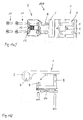
- FIG. 1 illustrated first embodiment of a hinge part 100 comprises an adjustment part 1, to which integrally a hinge part 2 is formed, which comprises a receptacle 3 for a not shown in the drawing, known adjustment sleeve of a hinge pin.
- the adjustment part 1 two parallel to each other and perpendicular to the longitudinal axis of the receptacle 3 extending straight guides 4 are provided in the form of slot-shaped apertures 5.
- the middle between the slot-shaped openings is an outwardly open, fork-shaped carrier. 6
- the band part 100 comprises a mounting part 7, on which in Fig. 1 shown on the right first pass extensions 8 and in Fig. 1 shown second pass extensions 9 each pair in the direction of the longitudinal extent of the receptacle 3 are arranged one above the other.
- the first pass extensions 8 have a significantly greater length than the second pass extensions 9.
- the passport extensions 8, 9 are formed dome-like. They comprise expansion screws 10, 11 which can be screwed into inner volumes, tapering towards the end, of the first and second passport extensions 8, 9, so that they spread apart in their slotted regions. Instead of the expansion screws can be used also in the inner volumes of pressable Sp Dahlite.
- an internal thread 12 is provided, in which a complementary external thread 13 having adjusting screw is screwed.
- the latter comprises an annular groove 14, which is in engagement with the driver 6.
- FIG. 1 illustrated embodiment of the hinge part 100 of the invention is intended for exclusive attachment of a visible side, and front of the multi-chamber hollow section.
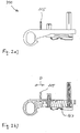
- FIG. 2 illustrated, second embodiment of a hinge portion 200 according to the invention in that it additionally comprises a mounting bracket 115 which is provided for encompassing a vertical to the front side of the multi-chamber hollow profile and, for example, by means of not shown in the drawing, it passes through in holes fastening screws This page is screwed.
- the mounting bracket 115 is displaceable in the direction of arrow P and fixedly arranged in a desired displacement position on the mounting member 107. Otherwise, the band part 200 corresponds in its construction and its function to the band part 100 described above.
- Fig. 3 shows - schematically - an embodiment of the hinge part 300 according to the invention mounted on a multi-chamber hollow section H.
- the first pass extensions 8 protrude through holes in a mounting wall 16, which forms the front of the multi-chamber hollow section H, and by perforations in an inner wall 17, the part a metal reinforcement 18 is.
- the first and second pass extensions for example, expansion dowel like in Fig. 1 and 2 be formed represented. However, it is also possible any further design that ensures an at least almost play-free seat or a clamping fit in the walls 16, 17.
- the in Fig. 3 be designated 207 mounting member by means of one or more not shown in the drawing mounting screws to be secured, but then only need to engage in the mounting wall 16.
- FIG. 4 another variant of a hinge part 400 according to the invention is here designated 307 mounting member secured by an additional fastening screw 319. It is screwed from the inside into a Aufdeck Scheme A of the multi-chamber hollow section H, so that it is not visible from the outside with the wing closed and can not be unscrewed.
- the fixing screw 319 does not deteriorate the visual appearance of the tape and At the same time, security against burglary is increased since it can not be unscrewed when the sash is closed.
- the fastening screw 319 is screwed into a hereby designated 309 second pass extension from the front side thereof.
- the fastening extension 309 is designed in the manner of an expansion dowel so that the fastening screw 319, as it were, effects a press fit of the second fitting extension 309 in the fastening wall 16.
- 308 first pass extension is spreizdübelartig, for example, as the one with reference to Fig. 1 described trained. Again, however, any other design that ensures at least one essentially play-free seat or a clamping fit in the walls 16, 17, conceivable.
- first and second pass extensions 408, 409 designed expansible plug. Its outer circumferential surface is contoured, so as to improve the clamping action between the first and second passport extensions and the profile walls.
- the mounting part 507 additional holes 520 through which mounting screws, not shown in the drawing can be screwed into the mounting wall of the profile.
- first and second mating extensions 608, 609 are formed as rigid, cylindrical posts with contoured surfaces.
- the fixing of the mounting part 607 in the longitudinal direction of the extensions is then carried out exclusively with fastening screws, not shown in the drawing, which are screwed through holes 620 in the mounting wall of the profile.
- the first pass extensions 708 expansion dowel-like dowel-like, so that these holding forces in the longitudinal direction of the extensions cause the profile.
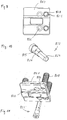
- the expansion dowel-like projections can be in the basis of Fig. 9 to 11 be configured illustrated.
- the first pass extensions 808 have a non-circular, approximately elliptical in cross-section inner contour 821.
- this inner contour 821 two longitudinal areas, which differ in that their approximately elliptical cross sections are rotated by 90 °.
- This embodiment is particularly by viewing the in Fig. 10 shown Sp Dr.s 822 clearly. It has a first, front elliptical area 823 and a second, rear elliptical area 824, which is rotated 90 ° relative to the first elliptical area 823.
- the spreader pin 822 comprises a rear cylindrical portion 825, which rests at least substantially free of play on a substantially cylindrical bore 826 of the mounting member 807.
- the spreader pins 822 are inserted in a rotational position in the respective passport extension after insertion of the fitting extensions in the profile bores, in which the elliptical areas 823, 824 are aligned with the respectively associated inner contour 821. Subsequently, the expansion pin is rotated with the aid of a rotary tool at an angle of about 45 °, wherein the respective attachment extension 807 is spread.
- the multi-chamber hollow profile holes 820 are again provided on the mounting part 807, through which fastening screws are screwed into the mounting wall of the profile.
Landscapes
- Engineering & Computer Science (AREA)
- Mechanical Engineering (AREA)
- Hinges (AREA)
Abstract
Description
- Die Erfindung betrifft ein Bandteil eines Scharnierbandes zur Befestigung an einer Befestigungswand eines Mehrkammer-Hohlprofils, insbesondere ein Flügelbandteil, wobei das Bandteil ein feststehendes an dem Mehrkammer-Hohlprofil anbringbares Montageteil und ein relativ zu dem Montageteil verlagerbares und in einer gewünschten Verlagerungsstellung festlegbares Verstellteil umfasst.
- Ein derartiges Bandteil ist beispielsweise aus der
EP 1 106 763 B1 bekannt. Die Befestigung des Montageteils an der Befestigungswand erfolgt mit Hilfe von sechs Befestigungsschrauben, die das Montageteil in hierfür vorgesehenen Bohrungen durchsetzen. - Aufgrund der stetig ansteigenden Anforderungen an die Wärmedämmung von Gebäuden bestehen heute die Hohlkammerprofile regelmäßig aus Mehrkammerprofilen, in die meist mehrere Isolierkammern integriert sind. Damit auch die Verglasung die hohen Anforderungen an die Wärmedämmung erfüllt, wird regelmäßig zumindest eine Dreifachverglasung vorgesehen. Aufgrund der hierdurch bedingten Gewichtszunahme weisen insbesondere Kunststoffprofile Metallarmierungen auf, damit diese Profile auch die hohen Gewichte ohne beachtliche Verformung des Profils aufnehmen können. Damit das Gewicht der durch die Metallarmierung ohnehin schweren Kunststoffprofile möglichst gering gehalten wird, sind die Wandstärken der Trennwände zwischen den einzelnen Profilkammern gering bemessen.
- Um bei derartigen Mehrkammer-Hohlprofilen ausreichend hohen Haltekräfte bewirken zu können, müssen zur Befestigung des aus der
EP 1 106 763 B1 bekannten Bandteil zumindest ein Teil der Befestigungsschrauben bis in die Metallarmierung hineingeschraubt werden. Hierdurch wird auf das Montageteil eine Kraft ausgeübt, die versucht, es gegen die Metallarmierung zu ziehen. Hierdurch kommt es regelmäßig zu unerwünschten Verformungen der Befestigungswand. Diese Verformungen führen zu einer erheblichen Verschlechterung der Statik, weil das erforderliche Anzugsmoment nicht erreicht wird, des optischen Erscheinungsbildes und der Justierfähigkeit, da das Verlagerungsteil gegen das Montageteil regelmäßig nur bei nicht oder nur geringfügig verformter Befestigungswand verlagert werden kann. - Der Erfindung liegt daher die Aufgabe zugrunde, ein Bandteil der eingangs genannten Art bereitzustellen, welches besser zur Befestigung an Mehrkammer-Hohlprofilen geeignet ist.
- Diese Aufgabe wird durch das in Anspruch 1 wiedergegebene Band gelöst.
- Bei diesem Bandteil umfasst das Montageteil erfindungsgemäß mindestens einen ersten Passfortsatz, der zum zumindest nahezu spielfreien Eingriff in Lochungen in der Befestigungswand und in der Innenwand vorgesehen ist, und mindestens einen zweiten Passfortsatz, der zum zumindest nahezu spielfreien Eingriff in Lochungen nur der Befestigungswand vorgesehen ist.
- Es hat sich gezeigt, dass durch diesen Eingriff der Passfortsätze überraschend hohe Haltekräfte vom Bandteil auf das Mehrkammer-Hohlprofil übertragen werden können, ohne dass es zu beachtenswerten Profilverformungen kommt. Denn Klemmkräfte, die zwischen dem Montageteil und der Innenwandung wirken, werden zur Krafteinleitung nicht mehr benötigt. Daher kann eine Festlegung des Montageteils an der Befestigungswand beispielsweise erfolgen, indem zumindest eine vorzugsweise selbstbohrende Befestigungsschraube vorgesehen wird, die jedoch lediglich in die Befestigungswandung eingreifen muss, wodurch eine Verformung des Mehrkammer-Hohlprofils beim Anziehen der Befestigungsschraube vermieden wird.
- Besonders bevorzugt ist es, den mindestens einen ersten und/oder mindestens einen zweiten Passfortsatz spreizdübelartig auszubilden. Mit "spreizdübelartig" ist gemeint, dass Maßnahmen vorgesehen sind, mit welchen der Außendurchmesser des Passfortsatzes zumindest über einen Teil seiner Länge vergrößerbar ist, um so seinen Außenumfang gegen die Ränder der Lochungen in der Befestigungswand und der Innenwand pressen zu können. Überraschenderweise hat sich gezeigt, dass für viele Anwendungsfälle insbesondere bei Mehrkammer-Hohlprofilen, bei denen die Innenwand Teil einer Armierung, insbesondere aus Metall ist, allein durch das Aufspreizen ausreichend hohe Haltekräfte erzielt werden.
- Bei einer ersten bevorzugten Variante findet zum Aufspreizen ein in ein Innenvolumen des spreizdübelartigen Passfortsatzes eintreibbarer Spreizstift oder vorzugsweise eine einschraubbare Spreizschraube Verwendung. Diese Ausgestaltung ist insbesondere für eine einmalige, unlösbare Befestigung des Montageteils an dem Mehrkammer-Hohlprofil geeignet, da sie einfach und kostengünstig herstellbar ist, der Spreizstift aber regelmäßig nur unter Schwierigkeiten wieder entfernt werden kann.
- Insbesondere für eine wieder lösbare Befestigung ist eine zweite Ausführungsform des spreizdübelartigen Passfortsatzes geeignet, bei welcher dieser eine unrunde Innenkontur umfasst, und ein Spreizstift vorgesehen ist, der eine etwa komplementäre Außenkontur aufweist, so dass er in einer bestimmten Winkelstellung zumindest im wesentlichen ohne Aufspreizen des Passfortsatzes in diesen einbringbar ist und durch eine Drehung um seine Längsachse beispielsweise um einen Winkel von 90° ein Aufspreizen des Passfortsatzes bewirkt wird. Beispielsweise können der Querschnitt des Innenvolumens des Passfortsatzes und der Außenquerschnitt des Spreizstiftes etwa elyptisch ausgebildet sein.
- Die mit den Passfortsätzen erzielbaren Haltekräfte können weiter erhöht werden, wenn diese konturierte Oberflächen aufweisen. Mit "konturiert" ist jede Ausgestaltung gemeint, die zu einer formschlüssigen Wechselwirkung zwischen Passfortsatz und Lochungsrand der jeweiligen Wandung führt. Beispielhaft sei hier eine Riffelung quer zur Längserstreckung des Passfortsatzes genannt.
- Die Passfortsätze können an dem Montageteil derart angeordnet sein, dass sie das Verstellteil in einer Geradführung durchgreifen. Die Passfortsätze dienen dann sogleich der Führung des Verstellteils während der Verstellung und der gewünschten Verstellposition, so dass auf weitere Maßnahmen zur Führung des Führungsteils verzichtet werden kann.
- Soll das Bandteil zur Befestigung an einem Aufdeck-Mehrkammerhohlprofil, d.h. einem solchen, wo ein Teil des Mehrkammer-Hohlprofils bei einem geschlossenen Flügel das benachbarte Profil teilweise überdeckt, geeignet sein, so ist der zweite Passfortsatz vorzugsweise zum Eingriff in eine Lochung in der Befestigungswand im Aufdeckbereich vorgesehen. Aufgrund dieser Maßnahme wird der Abstand zwischen der Scharnierachse und dem senkrecht zur Scharnierachse gesehen nächstliegenden Passfortsatz und somit der Hebel, über den Haltekräfte in das Mehrkammer-Hohlprofil eingeleitet werden, möglichst klein gehalten.
- Im Falle des Aufdeck-Mehrkammerhohlprofils kann der zweite Passfortsatz zusätzlich ein Befestigungsmittel, vorzugsweise eine Schraube umfassen, mit welcher er mit der der Befestigungswand gegenüberliegenden Aufdeckwand des Aufdeckbereichs befestigbar ist. In diesem Falle werden im Aufdeckbereich über den zweiten Passfortsatz Kräfte nicht nur in die Befestigungswand, sondern auch in die Aufdeckwand eingeleitet, so dass sich diese Variante für die Übertragung besonders hoher Haltekräfte und damit besonders schwerer Flügel eignet.
- Bei dem erfindungsgemäßen Bandteil können mehrere erste Passfortsätze und mehrere zweite Passfortsätze vorgesehen sein. Sowohl die ersten, als auch die zweiten Passfortsätze können jeweils parallel zur Scharnierachse gesehen übereinander angeordnet sein. Für eine Vielzahl von Anwendungsfällen ist es für die Übertragung der zu erwartenden Haltekräfte ausreichend, jeweils zwei parallel zur Scharnierachse gesehen übereinander angeordnete erste und zweite Passfortsätze vorzusehen, die senkrecht zur Scharnierachse voneinander beabstandet sind.
- In der Zeichnung sind Ausführungsbeispiele des erfindungsgemäßen Bandteils schematisch dargestellt. Es zeigen:
- Fig. 1a) bis d)
- ein erstes Ausführungsbeispiel in einer perspektivischen Explosionsdarstellung, in einer Explosionsdarstellung gemäß Ansicht a) von oben, in einer Aufsicht im zusammengefügten Zustand sowie eine Ansicht des zusammengefügten Bandteils von oben;
- Fig. 2a) und b)
- eine Ansicht eines weiteren Ausführungsbeispiels in einer
Fig. 1b ) entsprechenden Ansicht sowie im Schnitt durch die von einem ersten und einem zweiten Passfortsatz definierten Ebene; - Fig. 3
- ein Ausführungsbeispiel des erfindungsgemäßen Bandteils in einer
Fig. 1d ) entsprechenden Ansicht, jedoch an einem Mehrkammer-Hohlprofil montiert; - Fig. 4
- ein weiteres Ausführungsbeispiel in einer
Fig. 3 entsprechenden Ansicht, jedoch teilgeschnitten; - Fig. 5 bis 8
- Einzeldarstellungen von Montageteilen verschiedener Ausführungsformen des erfindungsgemäßen Bandteils sowie
- Fig. 9
- das Montageteil einer weiteren Ausführungsform des erfindungsgemäßen Bandteils in einer Aufsicht, die Ansicht eines Spreizstiftes sowie eine perspektivische Ansicht dieses Montageteils samt Spreizstift.
- Das in
Fig. 1 dargestellte erste Ausführungsbeispiel eines erfindungsgemäßen Bandteils 100 umfasst ein Verstellteil 1, an welches einstückig ein Scharnierteil 2 angeformt ist, welches eine Aufnahme 3 für eine in der Zeichnung nicht dargestellte, an sich bekannte Verstellbuchse eines Bandbolzens umfasst. In das Verstellteil 1 sind zwei parallel zueinander und senkrecht zur Längsachse der Aufnahme 3 verlaufende Geradführungen 4 in Form von langlochförmigen Durchbrüchen 5 vorgesehen. In der Mitte zwischen den langlochförmigen Durchbrechungen befindet sich ein nach außen offener, gabelförmiger Mitnehmer 6. - Ferner umfasst das Bandteil 100 ein Montageteil 7, an welchem in
Fig. 1 rechts dargestellt erste Passfortsätze 8 und inFig. 1 links dargestellte zweite Passfortsätze 9 jeweils paarweise in Richtung der Längserstreckung der Aufnahme 3 übereinander angeordnet sind. Die ersten Passfortsätze 8 weisen eine deutlich größere Länge als die zweiten Passfortsätze 9 auf. - Bei dem in
Fig. 1 dargestellten Ausführungsbeispiel sind die Passfortsätze 8, 9 spreizdübelartig ausgebildet. Sie umfassen Spreizschrauben 10, 11, die in sich zum Ende hin verjüngende Innenvolumina der ersten und zweiten Passfortsätze 8, 9 hinein einschraubbar sind, so dass sich diese in ihren geschlitzten Bereichen aufspreizen. Anstatt der Spreizschrauben können auch in die Innenvolumina eindrückbare Spreizstifte Verwendung finden. - In dem Montageteil ist ein Innengewinde 12 vorgesehen, in welches eine ein komplementäres Außengewinde 13 aufweisende Verstellspindel eingedreht ist. Letztere umfasst eine Ringnut 14, welche in Eingriff mit dem Mitnehmer 6 steht. Wie insbesondere aus
Fig. 1c ) sinnfällig wird, verlagern sich das Verstellteil 1 und das Montageteil 7 relativ zueinander, wenn die Verstellspindel 13 beispielsweise durch stirnseitigen Ansatz eines in der Zeichnung nicht dargestellten, geeigneten Drehwerkzeugs drehbetätigt wird. Da die ersten und zweiten Passfortsätze die langlochförmigen Durchbrechungen im wesentlichen spielfrei durchsetzen, wird das Verstellteil 1 gegenüber dem Montageteil 7 geführt. - Das in
Fig. 1 dargestellte Ausführungsbeispiel des erfindungsgemäßen Bandteils 100 ist zur ausschließlichen Befestigung von einer Sichtseite, auch Vorderseite des Mehrkammer-Hohlprofils bestimmt. Hiervon unterscheidet sich das inFig. 2 dargestellte, zweite Ausführungsbeispiel eines erfindungsgemäßen Bandteils 200 darin, dass es zusätzlich einen Befestigungswinkel 115 umfasst, der für ein Umgreifen einer zur Vorderseite senkrechten Seite des Mehrkammer-Hohlprofils vorgesehen ist und beispielsweise mit Hilfe von in der Zeichnung nicht dargestellten, ihn in Lochungen durchsetzenden Befestigungsschrauben mit dieser Seite verschraubbar ist. Um das Bandteil 200 an verschiedene Profile anpassen zu können, ist der Befestigungswinkel 115 in Richtung des Pfeiles P verlager- und in einer gewünschten Verlagerungsstellung festlegbar an dem Montageteil 107 angeordnet. Ansonsten entspricht das Bandteil 200 in seinem Aufbau und seiner Funktion dem oben beschriebenen Bandteil 100. -
Fig. 3 zeigt - schematisch - ein Ausführungsbeispiel des erfindungsgemäßen Bandteils 300 montiert an einem Mehrkammer-Hohlprofil H. Die ersten Passfortsätze 8 ragen durch Lochungen in einer Befestigungswand 16, welche die Vorderseite des Mehrkammer-Hohlprofils H bildet, und durch Lochungen in einer Innenwand 17, die Teil einer Metallarmierung 18 ist. Die zweiten Passfortsätze 9 hingegen durchsetzen lediglich Lochungen in der Befestigungswand 16. - Die ersten und zweiten Passfortsätze können beispielsweise spreizdübelartig wie in
Fig. 1 und2 dargestellt ausgebildet sein. Es ist jedoch ebenfalls jede weitere Gestaltung möglich, die einen zumindest nahezu spielfreien Sitz oder einen Klemmsitz in den Wandungen 16, 17 sicherstellt. Zusätzlich kann das inFig. 3 mit 207 bezeichnete Montageteil mit Hilfe einer oder mehrerer in der Zeichnung nicht dargestellter Befestigungsschrauben gesichert sein, die dann jedoch lediglich in die Befestigungswand 16 eingreifen müssen. - Bei der schematisch in
Fig. 4 dargestellten, weiteren Variante eines erfindungsgemäßen Bandteils 400 ist das hier mit 307 bezeichnete Montageteil durch eine zusätzliche Befestigungsschraube 319 gesichert. Sie ist von innen in einen Aufdeckbereich A des Mehrkammer-Hohlprofils H eingedreht, so dass sie bei geschlossenem Flügel von außen nicht sichtbar ist und auch nicht herausgedreht werden kann. Durch diese Anordnung verschlechtert die Befestigungsschraube 319 daher nicht das optische Erscheinungsbild des Bandes und erhöht gleichzeitig ist Einbruchssicherheit, da sie bei geschlossenem Flügel nicht herausgedreht werden kann. - Die Befestigungsschraube 319 ist in einen hiermit 309 bezeichneten zweiten Passfortsatz von dessen Stirnseite her eingedreht. Der Befestigungsfortsatz 309 ist spreizdübelartig ausgebildet, so dass die Befestigungsschraube 319 gleichsam einen Presssitz des zweiten Passfortsatzes 309 in der Befestigungswand 16 bewirkt. Auch der hier mit 308 bezeichnete erste Passfortsatz ist spreizdübelartig, beispielsweise wie derjenige anhand von
Fig. 1 beschriebene ausgebildet. Wiederum ist jedoch auch jede andere Ausgestaltung, die zumindest einen im wesentlichen spielfreien Sitz oder einen Klemmsitz in den Wandungen 16, 17 sicherstellt, denkbar. - In den
Fig. 5 bis 9 sind verschiedene Ausgestaltungen von Montageteilen dargestellt. - Bei dem Montageteil 407 gemäß
Fig. 5 sind die ersten und zweiten Passfortsätze 408, 409 spreizdübelartig ausgestaltet. Ihre äußere Mantelfläche ist konturiert, um so die Klemmwirkung zwischen den ersten und zweiten Passfortsätzen und den Profilwandungen zu verbessern. - Bei dem in
Fig. 6 dargestellten Ausführungsbeispiel weist das Montageteil 507 zusätzliche Bohrungen 520 auf, durch welche in der Zeichnung nicht dargestellte Befestigungsschrauben in die Befestigungswand des Profils eindrehbar sind. - In
Fig. 7 sind die ersten und zweiten Passfortsätze 608, 609 als starr, zylindrische Zapfen mit konturierten Oberflächen ausgebildet. Die Festlegung des Montageteils 607 in Längsrichtung der Fortsätze erfolgt dann ausschließlich mit in der Zeichnung nicht dargestellten Befestigungsschrauben, die durch Bohrungen 620 in die Befestigungswand des Profils eingeschraubt werden. - Bei dem Montageteil 707 in
Fig. 8 sind im Unterschied zum Montageteil 607 die ersten Passfortsätze 708 spreizdübelartig ausgebildet, so dass auch diese Haltekräfte in Längsrichtung der Fortsätze an dem Profil bewirken. - Die spreizdübelartigen Fortsätze können in der anhand von
Fig. 9 bis 11 dargestellten Weise ausgestaltet sein. - Die ersten Passfortsätze 808 weisen eine unrunde, im Querschnitt etwa elyptische Innenkontur 821 auf. Bei dem in
Fig. 9 bis 11 dargestellten Ausführungsbeispiel weist diese Innenkontur 821 zwei Längsbereiche auf, die sich darin unterscheiden, dass ihre etwa elyptischen Querschnitte um 90° verdreht sind. Diese Ausgestaltung wird insbesondere durch Ansicht des inFig. 10 dargestellten Spreizstifts 822 deutlich. Er weist einen ersten, vorderen elyptischen Bereich 823 sowie einen zweiten, hinteren elyptischen Bereich 824 auf, der gegenüber dem ersten elyptischen Bereich 823 um 90° gedreht ist. Ferner umfasst der Spreizstift 822 einen hinteren zylindrischen Bereich 825, welcher zumindest im wesentlichen spielfrei an einer im wesentlichen zylindrischen Bohrung 826 des Montageteils 807 anliegt. Zum Festsetzen des Montageteils 807 an einem Mehrkammer-Hohlprofil werden nach Einführen der Passfortsätze in die Profilbohrungen die Spreizstifte 822 in einer Drehstellung in den jeweiligen Passfortsatz eingesetzt, in welcher die elyptischen Bereiche 823, 824 mit der jeweils zugehörigen Innenkontur 821 fluchten. Anschließend wird der Spreizstift unter Zuhilfenahme eines Drehwerkzeugs um einen Winkel von etwa 45° gedreht, wobei der jeweilige Befestigungsfortsatz 807 aufgespreizt wird. Zur zusätzlichen Befestigung am Mehrkammer-Hohlprofil sind an dem Montageteil 807 wiederum Bohrungen 820 vorgesehen, durch welche Befestigungsschrauben in die Befestigungswand des Profils eindrehbar sind. -
- 100, 200, 300, 400
- Bandteil
- 1
- Verstellteil
- 2
- Scharnierteil
- 3
- Aufnahme
- 4
- Geradführungen
- 5
- langlochförmige Durchbrechungen
- 6
- Mitnehmer
- 7, 107, 207, 307, 407, 507, 607, 707, 807
- Montageteil
- 8, 408, 608, 708, 808
- erste Passfortsätze
- 9, 309, 409
- zweite Passfortsätze
- 10
- Spreizschraube
- 11
- Spreizschraube
- 12
- Innengewinde
- 13
- Verstellspindel
- 14
- Ringnut
- 115
- Befestigungswinkel
- 16
- Befestigungswand
- 17
- Innenwand
- 18
- Metallarmierung
- 319
- Befestigungsschraube
- 520, 620
- Bohrungen
- 821
- Innenkontur
- 822
- Spreizstift
- 823
- erster elyptischer Bereich
- 824
- zweiter elyptischer Bereich
- 825
- zylindrischer Bereich
- 826
- Bohrung
- A
- Aufdeckbereich
- H
- Mehrkammer-Hohlprofil
- P
- Pfeil
Claims (10)
- Bandteil (100, 200, 300, 400) eines Scharnierbandes, insbesondere Flügelbandteil, zur Befestigung an einer Befestigungswand (16) eines Mehrkammer-Hohlprofils (H) mit mindestens einer Innenwand (17),
wobei das Bandteil (100, 200, 300, 400) ein feststehend an dem Mehrkammer-Hohlprofil (H) anbringbares Montageteil (7, 107, 207, 307, 407, 507, 607, 707, 807) und ein relativ zu dem Montageteil (7, 107, 207, 307, 407, 507, 607, 707, 807) verlagerbares und in einer gewünschten Verlagerungsstellung festlegbares Verstellteil (1) umfasst,
dadurch gekennzeichnet,
dass das Montageteil (7, 107, 207, 307, 407, 507, 607, 807) mindestens einen ersten Passfortsatz (, 408, 608, 708), der zum zumindest nahezu spielfreien Eingriff in Lochungen in der Befestigungswand (16) und der Innenwand (17) vorgesehen ist,
und mindestens einen zweiten Passfortsatz (9, 309, 409), der zum zumindest nahezu spielfreien Eingriff in Lochungen nur in der Befestigungswand (16) vorgesehen ist, umfasst. - Bandteil nach Anspruch 1, dadurch gekennzeichnet, dass der erste und/oder der zweite Passfortsatz (8, 408, 608, 708) und/oder der zweite Passfortsatz (9, 309, 409) spreizdübelartig ausgebildet sind.
- Bandteil nach Anspruch 2, dadurch gekennzeichnet, dass der spreizdübelartige Passfortsatz einen Spreizstift oder eine Spreizschraube (10, 11) umfasst.
- Bandteil nach Anspruch 3, dadurch gekennzeichnet, dass der spreizdübelartige Passfortsatz (808) eine unrunde Innenkontur (821) umfasst, und dass ein Spreizstift (822) vorgesehen ist, der eine etwa komplementäre Außenkontur aufweist, so dass er in einer bestimmten Winkelstellung zumindest im wesentlichen ohne Aufspreizen des Passfortsatzes (808) in diesen einbringbar ist und durch eine Drehung um seine Längsachse ein Aufspreizen des Passfortsatzes (808) bewirkt wird.
- Bandteil nach einem der Ansprüche 1 bis 4, dadurch gekennzeichnet, dass der erste und/oder der zweite Passfortsatz (408, 608, 708, 808; 409) eine konturierte Oberfläche aufweist.
- Bandteil nach einem der Ansprüche 1 bis 5, dadurch gekennzeichnet, dass die ersten und zweiten Passfortsätze (8, 408, 608, 708, 808; 9, 309, 409) das Verstellteil (1) in Geradführungen (4) durchgreifen.
- Bandteil nach einem der Ansprüche 1 bis 6, zur Befestigung an einem Mehrkammer-Hohlprofil (H) mit Aufdeckbereich (A), dadurch gekennzeichnet, dass der zweite Passfortsatz (309) zum Eingriff in eine Lochung in der Befestigungswand (16) im Aufdeckbereich (A) vorgesehen ist.
- Bandteil nach Anspruch 7, dadurch gekennzeichnet, dass der zweite Passfortsatz (309) ein Befestigungsmittel, vorzugsweise eine Befestigungsschraube (319) umfasst, mit welcher der Passfortsatz (309) mit der der Befestigungswand gegenüberliegenden Aufdeckwand des Aufdeckbereichs (A) befestigbar ist.
- Bandteil nach einem der Ansprüche 1 bis 8, dadurch gekennzeichnet, dass mehrere, vorzugsweise zwei parallel zur Scharnierachse gesehen übereinander angeordnete erste Passfortsätze (8, 408, 608. 708, 808) und senkrecht zur Scharnierachse von den ersten Passfortsätzen beabstandet mehrere, vorzugsweise zwei, parallel zur Scharnierachse gesehen übereinander angeordnete zweite Passfortsätze (9, 309, 409) vorgesehen sind.
- Bandteil nach einem der Ansprüche 1 bis 9, dadurch gekennzeichnet, dass zumindest eine Bohrung (520, 620) in dem Montageteil (507, 607) für eine in die Befestigungswand (16) eindrehbarer, vorzugsweise selbstbohrende Befestigungsschraube vorgesehen ist.
Priority Applications (1)
| Application Number | Priority Date | Filing Date | Title |
|---|---|---|---|
| PL18194436T PL3447223T3 (pl) | 2009-11-27 | 2010-11-11 | Część zawiasowa zawiasu czołowego |
Applications Claiming Priority (3)
| Application Number | Priority Date | Filing Date | Title |
|---|---|---|---|
| DE202009015661U DE202009015661U1 (de) | 2009-11-27 | 2009-11-27 | Bandteil eines Scharnierbandes |
| PCT/EP2010/067261 WO2011064101A1 (de) | 2009-11-27 | 2010-11-11 | Bandteil eines scharnierbandes |
| EP10781640.7A EP2504511B1 (de) | 2009-11-27 | 2010-11-11 | Bandteil eines scharnierbandes |
Related Parent Applications (2)
| Application Number | Title | Priority Date | Filing Date |
|---|---|---|---|
| EP10781640.7A Division EP2504511B1 (de) | 2009-11-27 | 2010-11-11 | Bandteil eines scharnierbandes |
| EP10781640.7A Division-Into EP2504511B1 (de) | 2009-11-27 | 2010-11-11 | Bandteil eines scharnierbandes |
Publications (2)
| Publication Number | Publication Date |
|---|---|
| EP3447223A1 true EP3447223A1 (de) | 2019-02-27 |
| EP3447223B1 EP3447223B1 (de) | 2020-10-14 |
Family
ID=43502805
Family Applications (2)
| Application Number | Title | Priority Date | Filing Date |
|---|---|---|---|
| EP18194436.4A Active EP3447223B1 (de) | 2009-11-27 | 2010-11-11 | Bandteil eines scharnierbandes |
| EP10781640.7A Active EP2504511B1 (de) | 2009-11-27 | 2010-11-11 | Bandteil eines scharnierbandes |
Family Applications After (1)
| Application Number | Title | Priority Date | Filing Date |
|---|---|---|---|
| EP10781640.7A Active EP2504511B1 (de) | 2009-11-27 | 2010-11-11 | Bandteil eines scharnierbandes |
Country Status (5)
| Country | Link |
|---|---|
| EP (2) | EP3447223B1 (de) |
| DE (1) | DE202009015661U1 (de) |
| PL (2) | PL3447223T3 (de) |
| RU (1) | RU2549960C2 (de) |
| WO (1) | WO2011064101A1 (de) |
Cited By (1)
| Publication number | Priority date | Publication date | Assignee | Title |
|---|---|---|---|---|
| EP3848543A1 (de) * | 2020-01-10 | 2021-07-14 | Dr. Hahn GmbH & Co. KG | Bandlappen eines bandes zur scharniergelenkigen verbindung eines flügelprofils mit einem rahmenprofil und ein solches band |
Families Citing this family (4)
| Publication number | Priority date | Publication date | Assignee | Title |
|---|---|---|---|---|
| DE102015102868A1 (de) * | 2015-02-27 | 2016-09-01 | Gerd Möller | Beschlagsanordnung an Bauelementen |
| EP3181786A1 (de) * | 2015-12-17 | 2017-06-21 | WALA Spolka. z o.o. | Flügelbandelement |
| DE102022125007A1 (de) | 2022-09-28 | 2024-03-28 | Dr. Hahn Gmbh & Co. Kg | Bandteil eines Scharnierbandes |
| DE102022125005A1 (de) | 2022-09-28 | 2024-03-28 | Dr. Hahn Gmbh & Co. Kg | System mit Hohlprofil und Bandteil eines Scharnierbandes |
Citations (4)
| Publication number | Priority date | Publication date | Assignee | Title |
|---|---|---|---|---|
| DE19732535A1 (de) * | 1997-07-23 | 1999-01-28 | Haps & Sohn Gmbh & Co Kg | Verbesserung an Tür- oder Fensterbändern |
| EP0919686A2 (de) * | 1997-11-28 | 1999-06-02 | Niemann, Hans-Dieter | Tür- oder Fensterband |
| EP1106763A1 (de) * | 1999-12-07 | 2001-06-13 | Dr. Hahn GmbH & Co. KG | Bank für Türen, Fenster oder dergleichen |
| EP1191175A2 (de) * | 2000-09-21 | 2002-03-27 | Roto Frank Eisenwarenfabrik Aktiengesellschaft | Befestigungsanordnung für einen Beschlagsteil |
Family Cites Families (8)
| Publication number | Priority date | Publication date | Assignee | Title |
|---|---|---|---|---|
| AT292280B (de) * | 1968-08-30 | 1971-08-25 | Langensiepen Kg M | Dübel |
| DE7734037U1 (de) * | 1977-11-05 | 1978-02-23 | Fa. Richard Heinze, 4900 Herford | Montageplatte fuer scharniere, insbesondere moebelscharniere |
| US4749318A (en) * | 1985-06-26 | 1988-06-07 | Aktieselskabet J.H. Holm Holding | Nut |
| DE29718528U1 (de) * | 1997-10-18 | 1998-02-19 | Niemann, Hans Dieter, 50169 Kerpen | Tür- oder Fensterband |
| DE29818984U1 (de) * | 1998-10-24 | 2000-03-02 | Niemann, Hans Dieter, 50169 Kerpen | Tür- oder Fensterband |
| DE19962955C2 (de) * | 1999-12-24 | 2001-10-11 | Henke Paul Gmbh & Co Kg | Befestigungsvorrichtung |
| ITTO20040419A1 (it) * | 2004-06-23 | 2004-09-23 | Savio Spa | Elemento per il fissaggio di accessori a serramenti metallici |
| DE202007011076U1 (de) * | 2007-08-08 | 2007-10-18 | Haps + Sohn Gmbh + Co Kg | Bandanordnung mit Führungsprofil |
-
2009
- 2009-11-27 DE DE202009015661U patent/DE202009015661U1/de not_active Expired - Lifetime
-
2010
- 2010-11-11 EP EP18194436.4A patent/EP3447223B1/de active Active
- 2010-11-11 PL PL18194436T patent/PL3447223T3/pl unknown
- 2010-11-11 PL PL10781640T patent/PL2504511T3/pl unknown
- 2010-11-11 EP EP10781640.7A patent/EP2504511B1/de active Active
- 2010-11-11 RU RU2012126682/12A patent/RU2549960C2/ru active
- 2010-11-11 WO PCT/EP2010/067261 patent/WO2011064101A1/de not_active Ceased
Patent Citations (4)
| Publication number | Priority date | Publication date | Assignee | Title |
|---|---|---|---|---|
| DE19732535A1 (de) * | 1997-07-23 | 1999-01-28 | Haps & Sohn Gmbh & Co Kg | Verbesserung an Tür- oder Fensterbändern |
| EP0919686A2 (de) * | 1997-11-28 | 1999-06-02 | Niemann, Hans-Dieter | Tür- oder Fensterband |
| EP1106763A1 (de) * | 1999-12-07 | 2001-06-13 | Dr. Hahn GmbH & Co. KG | Bank für Türen, Fenster oder dergleichen |
| EP1191175A2 (de) * | 2000-09-21 | 2002-03-27 | Roto Frank Eisenwarenfabrik Aktiengesellschaft | Befestigungsanordnung für einen Beschlagsteil |
Cited By (1)
| Publication number | Priority date | Publication date | Assignee | Title |
|---|---|---|---|---|
| EP3848543A1 (de) * | 2020-01-10 | 2021-07-14 | Dr. Hahn GmbH & Co. KG | Bandlappen eines bandes zur scharniergelenkigen verbindung eines flügelprofils mit einem rahmenprofil und ein solches band |
Also Published As
| Publication number | Publication date |
|---|---|
| DE202009015661U1 (de) | 2011-04-28 |
| WO2011064101A1 (de) | 2011-06-03 |
| PL2504511T3 (pl) | 2020-08-10 |
| EP2504511A1 (de) | 2012-10-03 |
| RU2012126682A (ru) | 2014-01-20 |
| EP3447223B1 (de) | 2020-10-14 |
| PL3447223T3 (pl) | 2021-04-19 |
| RU2549960C2 (ru) | 2015-05-10 |
| EP2504511B1 (de) | 2020-02-19 |
Similar Documents
| Publication | Publication Date | Title |
|---|---|---|
| EP3613931B1 (de) | Baugruppe eines bandes zur um eine scharnierachse scharnierbeweglichen verbindung eines flügels an einem rahmen | |
| EP3680430B1 (de) | Gebäudetür | |
| EP3447223B1 (de) | Bandteil eines scharnierbandes | |
| DE19607029C1 (de) | Vorrichtung zur Befestigung eines Beschlages in einer Zarge | |
| EP2913465B1 (de) | Bandanordnung für türen, fenster oder dergleichen | |
| DE69512261T2 (de) | Diebstahlsicherer profilsatz und profilstreifen hierfür | |
| EP0844348A1 (de) | Band für Türen oder Fenster | |
| DE102020121334B3 (de) | Türband zur schwenkbaren Lagerung eines Türflügels in einem Rahmen | |
| DE202015100200U1 (de) | Bandlappenanordnung eines Bandes | |
| DE102010020278A1 (de) | Vorrichtung zur Bereitstellung eines Befestigungspunktes an einem Profilelement | |
| DE19752619A1 (de) | Verbindungsbauteil für eine Fassadenkonstruktion und Fassadenkonstruktion | |
| EP1182315A1 (de) | Band für Türen, Fenster und dergleichen | |
| EP0996800B1 (de) | Halterung für befestigungszapfen eines fenster-, tür- oder möbelscharniers | |
| EP0524636B1 (de) | Band für Türen, Fenster u. dgl. sowie Führungsteil für die Bandzapfen derartiger Bänder | |
| EP1310622A1 (de) | Büchse für die Befestigung eines Beschlagteils an einem mit einem vorgesetzen Profilteil versehenen Hohlprofil | |
| EP3848543B1 (de) | Anordnung zur scharniergelenkigen verbindung eines flügelprofils mit einem rahmenprofil | |
| DE10114083C1 (de) | Stoßverbindung eines Kämpferhohlprofils mit einem Rahmen- oder Sprossenprofil | |
| EP2504512B1 (de) | Bandteil eines scharnierbandes | |
| EP2182157B1 (de) | Blende für einen Spalt zwischen einer Tür- oder Torzarge und Laibung | |
| DE202010000291U1 (de) | Bandlappenanordnung | |
| DE20304483U1 (de) | Band für Türen, Fenster o.dgl. | |
| DE7010559U (de) | Scharnierband, insbesondere fuer tueren und fenster. | |
| EP3121356A1 (de) | Anordnung eines scharniers an einem hohlkammerprofil | |
| EP0711897A1 (de) | Vorrichtung zum Ausüben bzw. Hervorbringen einer Befestigungsvorspannung oder Andrückkraft auf bzw. an Beschlagteile(n) | |
| DE19812997A1 (de) | Fenster, Tür o. dgl. mit einem Betätigungsgetriebe |
Legal Events
| Date | Code | Title | Description |
|---|---|---|---|
| PUAI | Public reference made under article 153(3) epc to a published international application that has entered the european phase |
Free format text: ORIGINAL CODE: 0009012 |
|
| STAA | Information on the status of an ep patent application or granted ep patent |
Free format text: STATUS: THE APPLICATION HAS BEEN PUBLISHED |
|
| AC | Divisional application: reference to earlier application |
Ref document number: 2504511 Country of ref document: EP Kind code of ref document: P |
|
| AK | Designated contracting states |
Kind code of ref document: A1 Designated state(s): AL AT BE BG CH CY CZ DE DK EE ES FI FR GB GR HR HU IE IS IT LI LT LU LV MC MK MT NL NO PL PT RO RS SE SI SK SM TR |
|
| STAA | Information on the status of an ep patent application or granted ep patent |
Free format text: STATUS: REQUEST FOR EXAMINATION WAS MADE |
|
| 17P | Request for examination filed |
Effective date: 20190510 |
|
| RBV | Designated contracting states (corrected) |
Designated state(s): AL AT BE BG CH CY CZ DE DK EE ES FI FR GB GR HR HU IE IS IT LI LT LU LV MC MK MT NL NO PL PT RO RS SE SI SK SM TR |
|
| STAA | Information on the status of an ep patent application or granted ep patent |
Free format text: STATUS: EXAMINATION IS IN PROGRESS |
|
| 17Q | First examination report despatched |
Effective date: 20191028 |
|
| GRAP | Despatch of communication of intention to grant a patent |
Free format text: ORIGINAL CODE: EPIDOSNIGR1 |
|
| STAA | Information on the status of an ep patent application or granted ep patent |
Free format text: STATUS: GRANT OF PATENT IS INTENDED |
|
| INTG | Intention to grant announced |
Effective date: 20200714 |
|
| GRAS | Grant fee paid |
Free format text: ORIGINAL CODE: EPIDOSNIGR3 |
|
| GRAA | (expected) grant |
Free format text: ORIGINAL CODE: 0009210 |
|
| STAA | Information on the status of an ep patent application or granted ep patent |
Free format text: STATUS: THE PATENT HAS BEEN GRANTED |
|
| AC | Divisional application: reference to earlier application |
Ref document number: 2504511 Country of ref document: EP Kind code of ref document: P |
|
| AK | Designated contracting states |
Kind code of ref document: B1 Designated state(s): AL AT BE BG CH CY CZ DE DK EE ES FI FR GB GR HR HU IE IS IT LI LT LU LV MC MK MT NL NO PL PT RO RS SE SI SK SM TR |
|
| REG | Reference to a national code |
Ref country code: GB Ref legal event code: FG4D Free format text: NOT ENGLISH |
|
| RIN1 | Information on inventor provided before grant (corrected) |
Inventor name: KARAKAYA, SINAN Inventor name: MATUSCHEK, ERHARD |
|
| REG | Reference to a national code |
Ref country code: AT Ref legal event code: REF Ref document number: 1323739 Country of ref document: AT Kind code of ref document: T Effective date: 20201015 Ref country code: CH Ref legal event code: EP |
|
| REG | Reference to a national code |
Ref country code: DE Ref legal event code: R096 Ref document number: 502010016777 Country of ref document: DE |
|
| REG | Reference to a national code |
Ref country code: IE Ref legal event code: FG4D Free format text: LANGUAGE OF EP DOCUMENT: GERMAN |
|
| REG | Reference to a national code |
Ref country code: NL Ref legal event code: FP |
|
| PG25 | Lapsed in a contracting state [announced via postgrant information from national office to epo] |
Ref country code: PT Free format text: LAPSE BECAUSE OF FAILURE TO SUBMIT A TRANSLATION OF THE DESCRIPTION OR TO PAY THE FEE WITHIN THE PRESCRIBED TIME-LIMIT Effective date: 20210215 Ref country code: RS Free format text: LAPSE BECAUSE OF FAILURE TO SUBMIT A TRANSLATION OF THE DESCRIPTION OR TO PAY THE FEE WITHIN THE PRESCRIBED TIME-LIMIT Effective date: 20201014 Ref country code: FI Free format text: LAPSE BECAUSE OF FAILURE TO SUBMIT A TRANSLATION OF THE DESCRIPTION OR TO PAY THE FEE WITHIN THE PRESCRIBED TIME-LIMIT Effective date: 20201014 Ref country code: GR Free format text: LAPSE BECAUSE OF FAILURE TO SUBMIT A TRANSLATION OF THE DESCRIPTION OR TO PAY THE FEE WITHIN THE PRESCRIBED TIME-LIMIT Effective date: 20210115 Ref country code: NO Free format text: LAPSE BECAUSE OF FAILURE TO SUBMIT A TRANSLATION OF THE DESCRIPTION OR TO PAY THE FEE WITHIN THE PRESCRIBED TIME-LIMIT Effective date: 20210114 |
|
| REG | Reference to a national code |
Ref country code: LT Ref legal event code: MG4D |
|
| PG25 | Lapsed in a contracting state [announced via postgrant information from national office to epo] |
Ref country code: ES Free format text: LAPSE BECAUSE OF FAILURE TO SUBMIT A TRANSLATION OF THE DESCRIPTION OR TO PAY THE FEE WITHIN THE PRESCRIBED TIME-LIMIT Effective date: 20201014 Ref country code: BG Free format text: LAPSE BECAUSE OF FAILURE TO SUBMIT A TRANSLATION OF THE DESCRIPTION OR TO PAY THE FEE WITHIN THE PRESCRIBED TIME-LIMIT Effective date: 20210114 Ref country code: LV Free format text: LAPSE BECAUSE OF FAILURE TO SUBMIT A TRANSLATION OF THE DESCRIPTION OR TO PAY THE FEE WITHIN THE PRESCRIBED TIME-LIMIT Effective date: 20201014 Ref country code: IS Free format text: LAPSE BECAUSE OF FAILURE TO SUBMIT A TRANSLATION OF THE DESCRIPTION OR TO PAY THE FEE WITHIN THE PRESCRIBED TIME-LIMIT Effective date: 20210214 Ref country code: SE Free format text: LAPSE BECAUSE OF FAILURE TO SUBMIT A TRANSLATION OF THE DESCRIPTION OR TO PAY THE FEE WITHIN THE PRESCRIBED TIME-LIMIT Effective date: 20201014 |
|
| PG25 | Lapsed in a contracting state [announced via postgrant information from national office to epo] |
Ref country code: HR Free format text: LAPSE BECAUSE OF FAILURE TO SUBMIT A TRANSLATION OF THE DESCRIPTION OR TO PAY THE FEE WITHIN THE PRESCRIBED TIME-LIMIT Effective date: 20201014 |
|
| REG | Reference to a national code |
Ref country code: CH Ref legal event code: PL |
|
| REG | Reference to a national code |
Ref country code: DE Ref legal event code: R097 Ref document number: 502010016777 Country of ref document: DE |
|
| PG25 | Lapsed in a contracting state [announced via postgrant information from national office to epo] |
Ref country code: LU Free format text: LAPSE BECAUSE OF NON-PAYMENT OF DUE FEES Effective date: 20201111 Ref country code: MC Free format text: LAPSE BECAUSE OF FAILURE TO SUBMIT A TRANSLATION OF THE DESCRIPTION OR TO PAY THE FEE WITHIN THE PRESCRIBED TIME-LIMIT Effective date: 20201014 Ref country code: LT Free format text: LAPSE BECAUSE OF FAILURE TO SUBMIT A TRANSLATION OF THE DESCRIPTION OR TO PAY THE FEE WITHIN THE PRESCRIBED TIME-LIMIT Effective date: 20201014 Ref country code: SK Free format text: LAPSE BECAUSE OF FAILURE TO SUBMIT A TRANSLATION OF THE DESCRIPTION OR TO PAY THE FEE WITHIN THE PRESCRIBED TIME-LIMIT Effective date: 20201014 Ref country code: RO Free format text: LAPSE BECAUSE OF FAILURE TO SUBMIT A TRANSLATION OF THE DESCRIPTION OR TO PAY THE FEE WITHIN THE PRESCRIBED TIME-LIMIT Effective date: 20201014 Ref country code: SM Free format text: LAPSE BECAUSE OF FAILURE TO SUBMIT A TRANSLATION OF THE DESCRIPTION OR TO PAY THE FEE WITHIN THE PRESCRIBED TIME-LIMIT Effective date: 20201014 Ref country code: EE Free format text: LAPSE BECAUSE OF FAILURE TO SUBMIT A TRANSLATION OF THE DESCRIPTION OR TO PAY THE FEE WITHIN THE PRESCRIBED TIME-LIMIT Effective date: 20201014 |
|
| PLBE | No opposition filed within time limit |
Free format text: ORIGINAL CODE: 0009261 |
|
| STAA | Information on the status of an ep patent application or granted ep patent |
Free format text: STATUS: NO OPPOSITION FILED WITHIN TIME LIMIT |
|
| PG25 | Lapsed in a contracting state [announced via postgrant information from national office to epo] |
Ref country code: DK Free format text: LAPSE BECAUSE OF FAILURE TO SUBMIT A TRANSLATION OF THE DESCRIPTION OR TO PAY THE FEE WITHIN THE PRESCRIBED TIME-LIMIT Effective date: 20201014 Ref country code: CH Free format text: LAPSE BECAUSE OF NON-PAYMENT OF DUE FEES Effective date: 20201130 Ref country code: LI Free format text: LAPSE BECAUSE OF NON-PAYMENT OF DUE FEES Effective date: 20201130 |
|
| 26N | No opposition filed |
Effective date: 20210715 |
|
| GBPC | Gb: european patent ceased through non-payment of renewal fee |
Effective date: 20210114 |
|
| PG25 | Lapsed in a contracting state [announced via postgrant information from national office to epo] |
Ref country code: IE Free format text: LAPSE BECAUSE OF NON-PAYMENT OF DUE FEES Effective date: 20201111 Ref country code: AL Free format text: LAPSE BECAUSE OF FAILURE TO SUBMIT A TRANSLATION OF THE DESCRIPTION OR TO PAY THE FEE WITHIN THE PRESCRIBED TIME-LIMIT Effective date: 20201014 |
|
| PG25 | Lapsed in a contracting state [announced via postgrant information from national office to epo] |
Ref country code: GB Free format text: LAPSE BECAUSE OF NON-PAYMENT OF DUE FEES Effective date: 20210114 Ref country code: SI Free format text: LAPSE BECAUSE OF FAILURE TO SUBMIT A TRANSLATION OF THE DESCRIPTION OR TO PAY THE FEE WITHIN THE PRESCRIBED TIME-LIMIT Effective date: 20201014 |
|
| REG | Reference to a national code |
Ref country code: AT Ref legal event code: MM01 Ref document number: 1323739 Country of ref document: AT Kind code of ref document: T Effective date: 20201111 |
|
| PG25 | Lapsed in a contracting state [announced via postgrant information from national office to epo] |
Ref country code: AT Free format text: LAPSE BECAUSE OF NON-PAYMENT OF DUE FEES Effective date: 20201111 |
|
| PGFP | Annual fee paid to national office [announced via postgrant information from national office to epo] |
Ref country code: CZ Payment date: 20211015 Year of fee payment: 12 |
|
| PG25 | Lapsed in a contracting state [announced via postgrant information from national office to epo] |
Ref country code: IS Free format text: LAPSE BECAUSE OF FAILURE TO SUBMIT A TRANSLATION OF THE DESCRIPTION OR TO PAY THE FEE WITHIN THE PRESCRIBED TIME-LIMIT Effective date: 20210214 Ref country code: MT Free format text: LAPSE BECAUSE OF FAILURE TO SUBMIT A TRANSLATION OF THE DESCRIPTION OR TO PAY THE FEE WITHIN THE PRESCRIBED TIME-LIMIT Effective date: 20201014 Ref country code: CY Free format text: LAPSE BECAUSE OF FAILURE TO SUBMIT A TRANSLATION OF THE DESCRIPTION OR TO PAY THE FEE WITHIN THE PRESCRIBED TIME-LIMIT Effective date: 20201014 |
|
| PG25 | Lapsed in a contracting state [announced via postgrant information from national office to epo] |
Ref country code: MK Free format text: LAPSE BECAUSE OF FAILURE TO SUBMIT A TRANSLATION OF THE DESCRIPTION OR TO PAY THE FEE WITHIN THE PRESCRIBED TIME-LIMIT Effective date: 20201014 |
|
| REG | Reference to a national code |
Ref country code: DE Ref legal event code: R082 Ref document number: 502010016777 Country of ref document: DE Representative=s name: PATENTANWAELTE KLUIN DEBELIUS WEBER PARTG MBB, DE |
|
| PGFP | Annual fee paid to national office [announced via postgrant information from national office to epo] |
Ref country code: TR Payment date: 20221109 Year of fee payment: 13 Ref country code: IT Payment date: 20221011 Year of fee payment: 13 |
|
| P01 | Opt-out of the competence of the unified patent court (upc) registered |
Effective date: 20230523 |
|
| PG25 | Lapsed in a contracting state [announced via postgrant information from national office to epo] |
Ref country code: CZ Free format text: LAPSE BECAUSE OF NON-PAYMENT OF DUE FEES Effective date: 20221111 |
|
| PG25 | Lapsed in a contracting state [announced via postgrant information from national office to epo] |
Ref country code: IT Free format text: LAPSE BECAUSE OF NON-PAYMENT OF DUE FEES Effective date: 20231111 |
|
| PG25 | Lapsed in a contracting state [announced via postgrant information from national office to epo] |
Ref country code: IT Free format text: LAPSE BECAUSE OF NON-PAYMENT OF DUE FEES Effective date: 20231111 |
|
| PGFP | Annual fee paid to national office [announced via postgrant information from national office to epo] |
Ref country code: NL Payment date: 20251119 Year of fee payment: 16 |
|
| PGFP | Annual fee paid to national office [announced via postgrant information from national office to epo] |
Ref country code: DE Payment date: 20251130 Year of fee payment: 16 |
|
| PGFP | Annual fee paid to national office [announced via postgrant information from national office to epo] |
Ref country code: FR Payment date: 20251120 Year of fee payment: 16 |
|
| PGFP | Annual fee paid to national office [announced via postgrant information from national office to epo] |
Ref country code: BE Payment date: 20251118 Year of fee payment: 16 |
|
| PGFP | Annual fee paid to national office [announced via postgrant information from national office to epo] |
Ref country code: PL Payment date: 20251031 Year of fee payment: 16 |