EP3447292A1 - Dispositif de guidage de gaz de type actionnement - Google Patents
Dispositif de guidage de gaz de type actionnement Download PDFInfo
- Publication number
- EP3447292A1 EP3447292A1 EP18186764.9A EP18186764A EP3447292A1 EP 3447292 A1 EP3447292 A1 EP 3447292A1 EP 18186764 A EP18186764 A EP 18186764A EP 3447292 A1 EP3447292 A1 EP 3447292A1
- Authority
- EP
- European Patent Office
- Prior art keywords
- plate
- suspension plate
- actuating
- guiding device
- gas
- Prior art date
- Legal status (The legal status is an assumption and is not a legal conclusion. Google has not performed a legal analysis and makes no representation as to the accuracy of the status listed.)
- Withdrawn
Links
- 239000000725 suspension Substances 0.000 claims abstract description 80
- 238000005452 bending Methods 0.000 claims abstract description 14
- 230000004044 response Effects 0.000 claims abstract description 11
- 230000017525 heat dissipation Effects 0.000 claims description 22
- 238000009413 insulation Methods 0.000 claims description 16
- OKTJSMMVPCPJKN-UHFFFAOYSA-N Carbon Chemical compound [C] OKTJSMMVPCPJKN-UHFFFAOYSA-N 0.000 claims description 12
- 229910021389 graphene Inorganic materials 0.000 claims description 12
- 239000012790 adhesive layer Substances 0.000 claims description 7
- 239000010410 layer Substances 0.000 claims description 4
- 229910052451 lead zirconate titanate Inorganic materials 0.000 claims description 4
- 239000000203 mixture Substances 0.000 claims description 4
- 239000003973 paint Substances 0.000 claims description 4
- 241001417527 Pempheridae Species 0.000 claims description 3
- HFGPZNIAWCZYJU-UHFFFAOYSA-N lead zirconate titanate Chemical compound [O-2].[O-2].[O-2].[O-2].[O-2].[Ti+4].[Zr+4].[Pb+2] HFGPZNIAWCZYJU-UHFFFAOYSA-N 0.000 claims description 3
- 229910001252 Pd alloy Inorganic materials 0.000 claims description 2
- 239000000853 adhesive Substances 0.000 claims description 2
- 230000001070 adhesive effect Effects 0.000 claims description 2
- 239000003822 epoxy resin Substances 0.000 claims description 2
- SWELZOZIOHGSPA-UHFFFAOYSA-N palladium silver Chemical compound [Pd].[Ag] SWELZOZIOHGSPA-UHFFFAOYSA-N 0.000 claims description 2
- 229920000647 polyepoxide Polymers 0.000 claims description 2
- 239000000843 powder Substances 0.000 claims description 2
- 230000000694 effects Effects 0.000 claims 1
- 230000001965 increasing effect Effects 0.000 description 7
- 238000004891 communication Methods 0.000 description 5
- 239000000463 material Substances 0.000 description 4
- 238000012986 modification Methods 0.000 description 3
- 230000004048 modification Effects 0.000 description 3
- 230000002093 peripheral effect Effects 0.000 description 3
- 230000009471 action Effects 0.000 description 2
- 238000006073 displacement reaction Methods 0.000 description 2
- 239000010935 stainless steel Substances 0.000 description 2
- 229910001220 stainless steel Inorganic materials 0.000 description 2
- RYGMFSIKBFXOCR-UHFFFAOYSA-N Copper Chemical compound [Cu] RYGMFSIKBFXOCR-UHFFFAOYSA-N 0.000 description 1
- 230000004075 alteration Effects 0.000 description 1
- 239000004020 conductor Substances 0.000 description 1
- 229910052802 copper Inorganic materials 0.000 description 1
- 239000010949 copper Substances 0.000 description 1
- 230000007423 decrease Effects 0.000 description 1
- 238000005516 engineering process Methods 0.000 description 1
- 230000002708 enhancing effect Effects 0.000 description 1
- 239000000945 filler Substances 0.000 description 1
- 230000001771 impaired effect Effects 0.000 description 1
- 239000011810 insulating material Substances 0.000 description 1
- 239000002184 metal Substances 0.000 description 1
- 229910052751 metal Inorganic materials 0.000 description 1
- 239000007769 metal material Substances 0.000 description 1
- 238000000034 method Methods 0.000 description 1
- 239000004033 plastic Substances 0.000 description 1
- 238000007639 printing Methods 0.000 description 1
Images


Classifications
-
- F—MECHANICAL ENGINEERING; LIGHTING; HEATING; WEAPONS; BLASTING
- F04—POSITIVE - DISPLACEMENT MACHINES FOR LIQUIDS; PUMPS FOR LIQUIDS OR ELASTIC FLUIDS
- F04B—POSITIVE-DISPLACEMENT MACHINES FOR LIQUIDS; PUMPS
- F04B45/00—Pumps or pumping installations having flexible working members and specially adapted for elastic fluids
- F04B45/04—Pumps or pumping installations having flexible working members and specially adapted for elastic fluids having plate-like flexible members, e.g. diaphragms
- F04B45/047—Pumps having electric drive
-
- H—ELECTRICITY
- H10—SEMICONDUCTOR DEVICES; ELECTRIC SOLID-STATE DEVICES NOT OTHERWISE PROVIDED FOR
- H10N—ELECTRIC SOLID-STATE DEVICES NOT OTHERWISE PROVIDED FOR
- H10N30/00—Piezoelectric or electrostrictive devices
- H10N30/50—Piezoelectric or electrostrictive devices having a stacked or multilayer structure
- H10N30/508—Piezoelectric or electrostrictive devices having a stacked or multilayer structure adapted for alleviating internal stress, e.g. cracking control layers
-
- H—ELECTRICITY
- H10—SEMICONDUCTOR DEVICES; ELECTRIC SOLID-STATE DEVICES NOT OTHERWISE PROVIDED FOR
- H10N—ELECTRIC SOLID-STATE DEVICES NOT OTHERWISE PROVIDED FOR
- H10N30/00—Piezoelectric or electrostrictive devices
- H10N30/80—Constructional details
- H10N30/87—Electrodes or interconnections, e.g. leads or terminals
- H10N30/871—Single-layered electrodes of multilayer piezoelectric or electrostrictive devices, e.g. internal electrodes
-
- H—ELECTRICITY
- H10—SEMICONDUCTOR DEVICES; ELECTRIC SOLID-STATE DEVICES NOT OTHERWISE PROVIDED FOR
- H10N—ELECTRIC SOLID-STATE DEVICES NOT OTHERWISE PROVIDED FOR
- H10N30/00—Piezoelectric or electrostrictive devices
- H10N30/80—Constructional details
- H10N30/87—Electrodes or interconnections, e.g. leads or terminals
- H10N30/877—Conductive materials
-
- H—ELECTRICITY
- H10—SEMICONDUCTOR DEVICES; ELECTRIC SOLID-STATE DEVICES NOT OTHERWISE PROVIDED FOR
- H10N—ELECTRIC SOLID-STATE DEVICES NOT OTHERWISE PROVIDED FOR
- H10N30/00—Piezoelectric or electrostrictive devices
- H10N30/80—Constructional details
- H10N30/88—Mounts; Supports; Enclosures; Casings
-
- F—MECHANICAL ENGINEERING; LIGHTING; HEATING; WEAPONS; BLASTING
- F02—COMBUSTION ENGINES; HOT-GAS OR COMBUSTION-PRODUCT ENGINE PLANTS
- F02M—SUPPLYING COMBUSTION ENGINES IN GENERAL WITH COMBUSTIBLE MIXTURES OR CONSTITUENTS THEREOF
- F02M51/00—Fuel-injection apparatus characterised by being operated electrically
- F02M51/06—Injectors peculiar thereto with means directly operating the valve needle
- F02M51/0603—Injectors peculiar thereto with means directly operating the valve needle using piezoelectric or magnetostrictive operating means
Definitions
- the present disclosure relates to an actuating-type gas guiding device, and more particularly to a miniature, slim and silent actuating-type gas guiding device.
- actuating-type gas guiding devices are widely used in oven blowers, dental light curing machines, range hoods, sweepers, projector heat-dissipation devices, air blowers, dehumidifiers, vacuum cleaners, air cleaners, refrigerators, micro refrigerators, hair dryers, air conditioners, fans, portable ice fans, portable fans, heat-dissipation seat cushions, external heat dissipation modules of the mobile phones, external heat dissipation modules of notebook computers, heat dissipation modules of lamps, heat dissipation modules of engines, power supply devices, or the like.
- the actuating-type gas guiding device is used for driving the airflow to guide the airflow, dissipate the heat or circulate the gas. Since the above actuating-type gas guiding device has a conventional fan structure, it is difficult to reduce the overall volume of the actuating-type gas guiding device and the volume of the actuating-type gas guiding device is limited. In other words, it is difficult to minimize the actuating-type gas guiding device. Moreover, when the actuator of the conventional actuating-type gas guiding device is enabled, unpleasant noise is generated and the heat-dissipating efficiency is impaired. That is, the conventional actuating-type gas guiding device is neither friendly nor comfortable to the user.
- An object of the present disclosure provides an actuating-type gas guiding device.
- the actuating-type gas guiding device includes a piezoelectric actuator.
- a piezoelectric element of the piezoelectric actuator When a piezoelectric element of the piezoelectric actuator is operated at a high frequency, a pressure gradient is generated to facilitate the gas to flow at a high speed along the non-scattered linear direction.
- the gas can be transferred silently, and the overall volume of the actuating-type gas guiding device is reduced and thinned. Therefore, the issues of having larger volume, thinning hardly and generating unpleasant noise encountered by the prior art are overcome.
- an actuating-type gas guiding device includes a main body and at least one piezoelectric actuator.
- the at least one piezoelectric actuator is disposed in the main body.
- the piezoelectric actuator includes a suspension plate, an outer frame, at least one bracket and a piezoelectric element.
- the suspension plate has a first surface and a second surface. The suspension plate is permitted to undergo a bending vibration.
- the outer frame is arranged around the suspension plate.
- the at least one bracket is connected between the suspension plate and the outer frame for elastically supporting the suspension plate.
- the piezoelectric element is attached on the first surface of the suspension plate. In response to a voltage applied to the piezoelectric element, the suspension plate is driven to undergo the bending vibration in a reciprocating manner. Consequently, gas is guided to flow in the main body along a non-scattered linear direction.
- the present discourse provides an actuating-type gas guiding device including at least one main body (not shown), at last one piezoelectric actuator 1, at least one suspension plate 11, at least one outer frame 12, at least one bracket 13 and at least one piezoelectric element 14.
- the number of the main body, the suspension plate 11, the outer frame 12 and the piezoelectric element 14 is exemplified by one for each in the following embodiments but not limited thereto. It is noted that each of the main body, the suspension plate 11, the outer frame 12 and the piezoelectric element 14 can also be provided in plural numbers.
- the actuating-type gas guiding device includes a main body (not shown) and at least one piezoelectric actuator 1.
- An example of the main body includes but is not limited to an oven blower, a dental light curing machine, a range hood, a sweeper, a projector heat-dissipation device, an air blower, a dehumidifier, a vacuum cleaner, an air cleaner, a refrigerator, a micro refrigerator, a hair dryer, an air conditioner, a fan, a portable ice fan, a portable fan, a heat-dissipation seat cushion, an external heat dissipation module of the mobile phone, an external heat dissipation module of a notebook computer, a heat dissipation module of a lamp, a heat dissipation module of an engine or a power supply device.
- the at last one piezoelectric actuator 1 is disposed in the main body.
- gas is guided to flow in the main body along a non-scattered linear direction.
- the purpose of transferring the gas is achieved according to the requirements of the main body.
- the number of the piezoelectric actuator 1 in the main body is increased. If plural piezoelectric actuators 1 are disposed in the main body, the plural piezoelectric actuators 1 are connected with each other in series or in parallel. Since the overall area of the piezoelectric actuators 1 is increased, a great deal of gas can be guided and transferred.
- the piezoelectric actuator 1 is disposed in the main body and includes a suspension plate 11, an outer frame 12, at least one bracket 13 and a piezoelectric element 14.
- the suspension plate 11 has a first surface 11c and a second surface 11b. Moreover, the suspension plate 11 can be subjected to bending vibration.
- the outer frame 12 is arranged around outside of the suspension plate 11.
- the at least one bracket 13 is connected between the suspension plate 11 and the outer frame 12, while the two ends of the bracket 13 are connected with the outer frame 12 and the suspension plate 11 respectively that the bracket 13 can elastically support the suspension plate 11.
- At least one vacant space 15 is formed between the bracket 13, the suspension plate 11 and the outer frame 12. The gas is allowed to flow through the at least one vacant space 15.
- the type and the number of the suspension plate 11, the outer frame 12 and the at least one bracket 13 are not limited and may be varied according to the practical requirements.
- the outer frame 12 is arranged around outside of the suspension plate 11.
- a conducting pin 12c is protruded outwardly from the outer frame 12 so as to be electrically connected with an external circuit (not shown), but not limited thereto.
- the suspension plate 11 of this embodiment is a stepped structure.
- the second surface 11b of the suspension plate 11 is further included a bulge 11a.
- the bulge 11a may be a circular convex structure.
- the bulge 11a of the suspension plate 11 is coplanar with a second surface 12a of the outer frame 12, while the second surface 11b of the suspension plate 11 is coplanar with a second surface 13a of the bracket 13.
- a first surface 11c of the suspension plate 11, a first surface 12b of the outer frame 12 and a first surface 13b of the bracket 13 are coplanar with each other.
- the piezoelectric element 14 is attached on the flat first surface 11c of the suspension plate 11.
- the suspension plate 11 may be a square plate structure with two flat surfaces, but the structure of the suspension plate 11 may be varied according to the practical requirements.
- the suspension plate 11, the bracket 13 and the outer frame 12 are integrally formed from a metal plate (e.g., a stainless steel plate).
- the length of a side of the piezoelectric element 14 is smaller than the length of a side of the suspension plate 11.
- the length of a side of the piezoelectric element 14 is equal to the length of a side of the suspension plate 11.
- the piezoelectric element 14 is a square plate structure corresponding to the suspension plate 11 in terms of the design.
- the piezoelectric element 14 is made of a mixture comprising a highly-piezoelectric material and graphene.
- the highly-piezoelectric material is lead zirconate titanate (PZT) piezoelectric powder.
- the percentage of the graphene is in the range between 0.1% and 20%. Due to the excellent piezoelectric property of lead zirconate titanate, the suspension plate 11 has good piezoelectric driving efficacy.
- the piezoelectric element 14 comprises two electrodes 14a and 14b. Each of the electrodes 14a and 14b is made of a mixture comprising silver-palladium alloy and graphene.
- the surface of the electrode 14a is coated with a thermal conduction layer 14c, wherein thermal conduction layer 14c is a synthesized paint that is doped with graphene.
- the thermal conduction layer 14c is used for increasing the thermal conductivity, so that the heat dissipation efficiency is enhanced.
- the electrode 14b is coated with an adhesive layer 14d.
- the adhesive layer 14d is an epoxy resin adhesive layer with doped graphene. Through the adhesive layer 14d, the piezoelectric element 14 is attached on the first surface 11c of the suspension plate 11.
- the use of the adhesive layer 14d reduces the impedance, increases the charge moving speed and increases the thermal conductivity, and thus the heat dissipation efficacy is enhanced.
- the piezoelectric element 14 is subjected to the bending deformation and the suspension plate 11 is subjected to a bending vibration in a reciprocating manner.
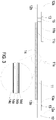
- the actuating-type gas guiding device further includes a gas inlet plate 16, a resonance plate 17, a first insulation plate 18a, a conducting plate 19 and a second insulation plate 18b.
- the suspension plate 11 is aligned with the resonance plate 17.
- the gas inlet plate 16, the resonance plate 17, the outer frame 12, the first insulation plate 18a, the conducting plate 19 and the second insulation plate 18b are stacked on each other sequentially.
- the gas inlet plate 16 is arranged beside the second surface 11b of the suspension plate 11, and the gas inlet plate 16 includes at least one inlet 16a.
- the gas inlet plate 16 includes four inlets 16a.
- the inlets 16a run through the gas inlet plate 16.
- the gas outside the device can be introduced into the gas inlet plate 16 through the at least one inlet 16a.
- the gas inlet plate 16 includes at least one convergence channel 16b in communication with the at least one inlet 16a of the gas inlet plate 16.
- a central cavity 16c is located at the central intersection of the convergence channels 16b.
- the central cavity 16c is in communication with the at least one convergence channel 16b.
- a first surface 16d of the gas inlet plate 16 is coated with a synthesized paint that is doped with graphene. The first surface 16d is used to increase the thermal conductivity for enhancing the heat dissipation efficiency.
- the at least one inlet 16a, the at least one convergence channel 16b and the central cavity 16c of the gas inlet plate 16 are integrally formed from a single structure.
- the central cavity 16c forms a convergence chamber for temporarily storing the gas.
- the gas inlet plate 16 may be, for example, made of stainless steel.
- the depth of the convergence chamber defined by the central cavity 16c may be equal to the depth of the at least one convergence channel 16b.
- the resonance plate 17 may be made of flexible material.
- the resonance plate 17 is disposed between the gas inlet plate 16 and the suspension plate 11, and the resonance plate 17 has a central aperture 17c aligned with the central cavity 16c of the gas inlet plate 16 which allows the gas to be transferred therethrough.
- the resonance plate 17 may be, for example, made of copper.
- the first insulation plate 18a, the conducting plate 19 and the second insulation plate 18b are stacked on each other sequentially and located under the outer frame 12, as shown in FIG. 3A .
- the profiles of the first insulation plate 18a, the conducting plate 19 and the second insulation plate 18b substantially match the profile of the outer frame 12.
- the first insulation plate 18a and the second insulation plate 18b may be made of an insulating material (e.g. a plastic material) for providing insulating efficacy.
- the conducting plate 19 may be made of an electrically conductive material (e.g. a metallic material) for providing electrically conducting efficacy.
- the conducting plate 19 may have a conducting pin 19a disposed thereon so as to be electrically connected with an external circuit (not shown).
- the conducting pin 12c of the outer frame 12 is electrically connected to the electrode 14a of the piezoelectric element 14.
- the conducting pin 19a of the conducting plate 19 is electrically connected to the electrode 14b of the piezoelectric element 14.
- the gas inlet plate 16, the resonance plate 17, the outer frame 12, the first insulation plate 18a, the conducting plate 19 and the second insulation plate 18b are stacked on each other sequentially. Consequently, the gas is allowed to flow through the actuating-type gas guiding device. Moreover, there is a gap h between the resonance plate 17 and the outer frame 12.
- the gap h between the resonance plate 17 and the outer frame 12 may be filled with a filler (e.g. a conductive adhesive) so that a depth from the resonance plate 17 to the bulge 11a of the suspension plate 11 can be maintained.
- the gap h ensures the proper distance between the resonance plate 17 and the bulge 11a of the suspension plate 11, so that the gas can be transferred quickly, the contact interference is reduced and the generated noise is largely reduced.
- the height of the outer frame 12 of the piezoelectric actuator 1 is increased, so that a gap is formed between the resonance plate 17 and the outer frame 12.
- a movable part 17a and a fixed part 17b of the resonance plate 17 are defined.
- the movable part 17a is around the central aperture 17c.
- a convergence chamber for converging the gas is defined by the movable part 17a of the resonance plate 17 and the gas inlet plate 16 collaboratively.
- a first chamber 10 is formed between the resonance plate 17, the suspension plate 11, the brackets 13 and the outer frame 12 for temporarily storing the gas.
- the first chamber 10 is in communication with the convergence chamber of the central cavity 16c of the gas inlet plate 16.
- the peripheral regions of the first chamber 10 are in communication with the gas channel through the vacant space 15 between the brackets 13.
- the piezoelectric element 14 vibrates along a vertical direction in a reciprocating manner by using the bracket 13 as a fulcrum.
- the piezoelectric element 14 vibrates along a first direction in response to the applied voltage. Since the resonance plate 17 is light and thin, the resonance plate 17 vibrates along the vertical direction in the reciprocating manner in resonance with the piezoelectric element 14. More especially, a region of the resonance plate 17 spatially corresponding to the central cavity 16c of the gas inlet plate 16 is also subjected to a bending deformation.
- the region of the resonance plate 17 corresponding to the central cavity 16c of the gas inlet plate 16 is the movable part 17a of the resonance plate 17.
- the movable part 17a of the resonance plate 17 corresponding to the central cavity 16c is subjected to the bending deformation because the movable part 17a of the resonance plate 17 is pushed by the gas and vibrated in response to the piezoelectric element 14.
- the gas is fed into the at least one inlet 16a of the gas inlet plate 16. Then, the gas is transferred to the central cavity 16c of the gas inlet plate 16 through the at least one convergence channel 16b.
- the gas is transferred through the central aperture 17c of the resonance plate 17 spatially corresponding to the central cavity 16c, and introduced into the first chamber 10 along the first direction.
- the resonance of the resonance plate 17 occurs. Consequently, the resonance plate 17 vibrates along the vertical direction in the reciprocating manner.
- FIG. 5B shows that during the vibration of the movable part 17a of the resonance plate 17, the movable part 17a moves along the first direction to contact and attach on the bulge 11a of the suspension plate 11, and a distance of the convergence chamber from the fixed part 17b of the resonance plate 17 to a region of the suspension plate 11 except the bulge 11a remains the same.
- a middle communication space of the first chamber 10 is closed, and the volume of the first chamber 10 is compressed.
- the gas is pushed moving toward peripheral regions of the first chamber 10, and flowing along the first direction through the vacant space 15 between the brackets 13.
- the movable part 17a of the resonance plate 17 returns to its original position when the movable part 17a vibrates along a second direction. While the piezoelectric element 14 vibrates along the second direction in response to an applied voltage, the volume of the first chamber 10 is compressed, which makes the gas in the first chamber 10 continuously pushed toward peripheral regions.
- the gas is continuously fed into the at least one inlet 16a of the gas inlet plate 16, and transferred to the convergence chamber of the central cavity 16c.
- the resonance plate 17 moves along the second direction, which is cause by the resonance of the suspension plate 11. That is, the movable part 17a of the resonance plate 17 also vibrates along the second direction. Consequently, it decreases the current of the gas from the at least one inlet 16a of the gas inlet plate 16 into the convergence chamber formed by the central cavity 16c.
- the movable part 17a of the resonance plate 17 has returned to its original position.
- the gap h between the resonance plate 17 and the outer frame 12 is helpful to increase maximum displacement along the vertical direction during the vibration.
- the configuration of the gap h between the resonance plate 17 and the outer frame 12 can increase the amplitude of up and down displacement of the resonance plate 17 during the vibration. Consequently, a pressure gradient is generated in the gas channels of the piezoelectric actuator 1 to facilitate the gas to flow at a high speed.
- the gas can be transmitted from the inlet side to the outlet side.
- the piezoelectric actuator 1 Even if a gas pressure exists at the outlet side, the piezoelectric actuator 1 still has the capability of pushing the gas to the gas channel while achieving the silent efficacy.
- the steps of FIGS. 5A to 5E may be done repeatedly. Consequently, the gas circulation is generated in which the ambient gas is transferred from the outside to the inside by the piezoelectric actuator 1. Moreover, the gas is transferred along a non-scattered linear direction.
- the actuating-type gas guiding device further includes a sensor (not shown).
- the sensor is disposed adjacent to the piezoelectric actuator 1.
- gas is guided to flow along a non-scattered linear direction and flow toward the sensor, so that the gas guided along the non-scattered linear direction is sensed by the sensor to generate an output data.
- the piezoelectric actuator 1 is used to guide airflow and provide the amount of air stably and uniformly. Since the sensor is provided with the amount of the air stably and uniformly, the response time of the sensor to the air is largely reduced and the air is monitored with precision.
- the sensor transmits the output data to a connection device (not shown).
- the information carried in the output data is displayed, stored and transmitted by the connection device. For example, the information carried in the output data contains the temperature, the flowrate, or the like.
- the present disclosure provides an actuating-type gas guiding device.
- the actuating-type gas guiding device includes a piezoelectric actuator.
- a piezoelectric element of the piezoelectric actuator When a piezoelectric element of the piezoelectric actuator is operated at a high frequency, a pressure gradient is generated to facilitate the gas to flow at a high speed along the non-scattered linear direction. Consequently, the gas can be transferred quickly and silently.
- the actuating-type gas guiding device is small and slim. In other words, the actuating-type gas guiding device of the present disclosure is industrially valuable.
Landscapes
- Engineering & Computer Science (AREA)
- Mechanical Engineering (AREA)
- General Engineering & Computer Science (AREA)
- Reciprocating Pumps (AREA)
- Apparatuses For Generation Of Mechanical Vibrations (AREA)
Applications Claiming Priority (1)
| Application Number | Priority Date | Filing Date | Title |
|---|---|---|---|
| TW106128914A TWI689664B (zh) | 2017-08-25 | 2017-08-25 | 致動氣體導流裝置 |
Publications (2)
| Publication Number | Publication Date |
|---|---|
| EP3447292A1 true EP3447292A1 (fr) | 2019-02-27 |
| EP3447292A8 EP3447292A8 (fr) | 2019-05-08 |
Family
ID=63113421
Family Applications (1)
| Application Number | Title | Priority Date | Filing Date |
|---|---|---|---|
| EP18186764.9A Withdrawn EP3447292A1 (fr) | 2017-08-25 | 2018-08-01 | Dispositif de guidage de gaz de type actionnement |
Country Status (4)
| Country | Link |
|---|---|
| US (1) | US11187226B2 (fr) |
| EP (1) | EP3447292A1 (fr) |
| JP (1) | JP7088780B2 (fr) |
| TW (1) | TWI689664B (fr) |
Cited By (2)
| Publication number | Priority date | Publication date | Assignee | Title |
|---|---|---|---|---|
| WO2020216414A1 (fr) * | 2019-04-25 | 2020-10-29 | Pi Ceramic Gmbh | Actionneur |
| CN113597192A (zh) * | 2020-04-30 | 2021-11-02 | 维沃移动通信有限公司 | 一种电子设备 |
Families Citing this family (5)
| Publication number | Priority date | Publication date | Assignee | Title |
|---|---|---|---|---|
| JP7429506B2 (ja) * | 2019-08-29 | 2024-02-08 | 太陽誘電株式会社 | 振動パネル及び電子機器 |
| TWI738175B (zh) * | 2020-01-08 | 2021-09-01 | 研能科技股份有限公司 | 具有氣體檢測功能之家居裝置 |
| CN113339244B (zh) * | 2020-02-18 | 2024-06-18 | 研能科技股份有限公司 | 薄型气体传输装置 |
| TWI785646B (zh) * | 2021-06-11 | 2022-12-01 | 研能科技股份有限公司 | 致動器 |
| TW202248533A (zh) * | 2021-06-11 | 2022-12-16 | 研能科技股份有限公司 | 微型鼓風機 |
Citations (3)
| Publication number | Priority date | Publication date | Assignee | Title |
|---|---|---|---|---|
| US20040108479A1 (en) * | 2000-12-01 | 2004-06-10 | Francis Garnier | Valves activated by electrically active polymers or by shape-memory materials, device containing same and method for using same |
| DE102014113888A1 (de) * | 2014-02-21 | 2015-08-27 | Lenovo (Beijing) Co., Ltd. | Wärmeableitungsvorrichtung und elektronisches Gerät |
| EP3203074A1 (fr) * | 2016-01-29 | 2017-08-09 | Microjet Technology Co., Ltd | Actionneur piézoélectrique |
Family Cites Families (20)
| Publication number | Priority date | Publication date | Assignee | Title |
|---|---|---|---|---|
| JPH05315663A (ja) * | 1992-05-08 | 1993-11-26 | Nec Corp | 電歪効果素子 |
| JP2002106470A (ja) | 2000-09-29 | 2002-04-10 | Matsushita Electric Works Ltd | ダイヤフラムポンプ |
| US8886334B2 (en) * | 2008-10-07 | 2014-11-11 | Mc10, Inc. | Systems, methods, and devices using stretchable or flexible electronics for medical applications |
| WO2011010484A1 (fr) * | 2009-07-22 | 2011-01-27 | コニカミノルタエムジー株式会社 | Corps piézoélectrique, transducteur à ultrasons, ultrasonographe médical, et instrument d'inspection ultrasonore non destructive |
| EP2508758B1 (fr) | 2009-12-04 | 2019-05-29 | Murata Manufacturing Co., Ltd. | Micro-soufflerie piézoélectrique |
| JP5528404B2 (ja) * | 2011-09-06 | 2014-06-25 | 株式会社村田製作所 | 流体制御装置 |
| KR20130056628A (ko) * | 2011-11-22 | 2013-05-30 | 삼성전기주식회사 | 고분자 압전 소자 |
| US9887346B2 (en) * | 2012-10-05 | 2018-02-06 | Nokia Technologies Oy | Apparatus and associated methods |
| CN103059257B (zh) | 2013-01-22 | 2014-08-20 | 北京市射线应用研究中心 | 一种以石墨烯作为导电通道的辐照改性聚氨酯压电阻尼材料及其制备方法 |
| KR102142526B1 (ko) | 2013-09-17 | 2020-08-07 | 삼성전자주식회사 | 압전 소자 및 그 제조방법 |
| JP6163662B2 (ja) * | 2014-04-28 | 2017-07-19 | 寧波墨西科技有限公司Ningbo Morsh Technology CO., LTD. | グラフェン複合粉体材料及びその製造方法 |
| FR3034256B1 (fr) * | 2015-03-24 | 2017-04-14 | Commissariat Energie Atomique | Dispositif piezoelectrique |
| JP2016207723A (ja) * | 2015-04-16 | 2016-12-08 | Jx金属株式会社 | 銅放熱材、銅放熱材用銅箔または銅合金箔、積層体、シールド材、電子機器及び銅放熱材の製造方法 |
| JP2017108047A (ja) * | 2015-12-11 | 2017-06-15 | ルネサスエレクトロニクス株式会社 | 半導体装置 |
| CN107023463A (zh) * | 2016-01-29 | 2017-08-08 | 研能科技股份有限公司 | 微型气压动力装置 |
| JP6273418B2 (ja) * | 2016-08-18 | 2018-02-07 | 株式会社メトラン | ポンプユニット、呼吸補助装置 |
| TWM545188U (zh) * | 2016-10-13 | 2017-07-11 | 研能科技股份有限公司 | 壓電泵浦之驅動系統 |
| CN106571423A (zh) * | 2016-10-27 | 2017-04-19 | 北京航空航天大学 | 一种针状水声换能器中的新型压电复合薄膜的制备方法 |
| TWM538545U (zh) * | 2016-11-10 | 2017-03-21 | 研能科技股份有限公司 | 壓電致動器 |
| TWM553376U (zh) * | 2017-08-25 | 2017-12-21 | Microjet Technology Co Ltd | 致動氣體導流裝置 |
-
2017
- 2017-08-25 TW TW106128914A patent/TWI689664B/zh active
-
2018
- 2018-08-01 EP EP18186764.9A patent/EP3447292A1/fr not_active Withdrawn
- 2018-08-01 US US16/051,767 patent/US11187226B2/en active Active
- 2018-08-21 JP JP2018154414A patent/JP7088780B2/ja active Active
Patent Citations (3)
| Publication number | Priority date | Publication date | Assignee | Title |
|---|---|---|---|---|
| US20040108479A1 (en) * | 2000-12-01 | 2004-06-10 | Francis Garnier | Valves activated by electrically active polymers or by shape-memory materials, device containing same and method for using same |
| DE102014113888A1 (de) * | 2014-02-21 | 2015-08-27 | Lenovo (Beijing) Co., Ltd. | Wärmeableitungsvorrichtung und elektronisches Gerät |
| EP3203074A1 (fr) * | 2016-01-29 | 2017-08-09 | Microjet Technology Co., Ltd | Actionneur piézoélectrique |
Cited By (3)
| Publication number | Priority date | Publication date | Assignee | Title |
|---|---|---|---|---|
| WO2020216414A1 (fr) * | 2019-04-25 | 2020-10-29 | Pi Ceramic Gmbh | Actionneur |
| CN113597192A (zh) * | 2020-04-30 | 2021-11-02 | 维沃移动通信有限公司 | 一种电子设备 |
| CN113597192B (zh) * | 2020-04-30 | 2024-02-02 | 维沃移动通信有限公司 | 一种电子设备 |
Also Published As
| Publication number | Publication date |
|---|---|
| US20190067553A1 (en) | 2019-02-28 |
| US11187226B2 (en) | 2021-11-30 |
| JP7088780B2 (ja) | 2022-06-21 |
| TWI689664B (zh) | 2020-04-01 |
| TW201912935A (zh) | 2019-04-01 |
| EP3447292A8 (fr) | 2019-05-08 |
| JP2019039428A (ja) | 2019-03-14 |
Similar Documents
| Publication | Publication Date | Title |
|---|---|---|
| US11187226B2 (en) | Actuating-type gas guiding device | |
| TWI626775B (zh) | 致動器 | |
| TWI686538B (zh) | 氣冷散熱裝置 | |
| US8325477B2 (en) | Vibrating device, jet flow generating device, electronic device, and manufacturing method of vibrating device | |
| TWI687151B (zh) | 氣冷散熱裝置及系統 | |
| US20190309744A1 (en) | Miniature cooling system | |
| US10356941B2 (en) | Air-cooling heat dissipation device | |
| TWI641310B (zh) | 氣冷散熱裝置 | |
| CN102238848A (zh) | 散热装置及其气流产生器 | |
| TW201831788A (zh) | 氣冷散熱裝置 | |
| JP7044663B2 (ja) | アクチュエータ | |
| US10687417B2 (en) | Air-cooling heat dissipation device | |
| TWI623686B (zh) | 氣冷散熱裝置 | |
| TWM553376U (zh) | 致動氣體導流裝置 | |
| CN211737429U (zh) | 致动气体导流装置 | |
| JP4844236B2 (ja) | ノズル、噴流発生装置、冷却装置及び電子機器 | |
| CN108278196A (zh) | 流体控制装置 | |
| TWM553498U (zh) | 致動器 | |
| CN108112216B (zh) | 气冷散热装置 | |
| CN108112214B (zh) | 气冷散热装置 | |
| CN109424527B (zh) | 致动气体导流装置 | |
| CN206585882U (zh) | 气冷散热装置及系统 | |
| CN211500945U (zh) | 流体控制装置 | |
| CN102130081A (zh) | 散热装置及其气流产生装置 | |
| CN108463085B (zh) | 气冷散热装置 |
Legal Events
| Date | Code | Title | Description |
|---|---|---|---|
| PUAI | Public reference made under article 153(3) epc to a published international application that has entered the european phase |
Free format text: ORIGINAL CODE: 0009012 |
|
| AK | Designated contracting states |
Kind code of ref document: A1 Designated state(s): AL AT BE BG CH CY CZ DE DK EE ES FI FR GB GR HR HU IE IS IT LI LT LU LV MC MK MT NL NO PL PT RO RS SE SI SK SM TR |
|
| AX | Request for extension of the european patent |
Extension state: BA ME |
|
| STAA | Information on the status of an ep patent application or granted ep patent |
Free format text: STATUS: THE APPLICATION IS DEEMED TO BE WITHDRAWN |
|
| 18D | Application deemed to be withdrawn |
Effective date: 20190828 |