EP3447323B1 - Embrayage pour un engin de chantier - Google Patents
Embrayage pour un engin de chantier Download PDFInfo
- Publication number
- EP3447323B1 EP3447323B1 EP18187464.5A EP18187464A EP3447323B1 EP 3447323 B1 EP3447323 B1 EP 3447323B1 EP 18187464 A EP18187464 A EP 18187464A EP 3447323 B1 EP3447323 B1 EP 3447323B1
- Authority
- EP
- European Patent Office
- Prior art keywords
- clutch
- line
- construction machine
- drive
- accordance
- Prior art date
- Legal status (The legal status is an assumption and is not a legal conclusion. Google has not performed a legal analysis and makes no representation as to the accuracy of the status listed.)
- Active
Links
Images




Classifications
-
- E—FIXED CONSTRUCTIONS
- E02—HYDRAULIC ENGINEERING; FOUNDATIONS; SOIL SHIFTING
- E02F—DREDGING; SOIL-SHIFTING
- E02F9/00—Component parts of dredgers or soil-shifting machines, not restricted to one of the kinds covered by groups E02F3/00 - E02F7/00
- E02F9/20—Drives; Control devices
- E02F9/202—Mechanical transmission, e.g. clutches, gears
-
- F—MECHANICAL ENGINEERING; LIGHTING; HEATING; WEAPONS; BLASTING
- F16—ENGINEERING ELEMENTS AND UNITS; GENERAL MEASURES FOR PRODUCING AND MAINTAINING EFFECTIVE FUNCTIONING OF MACHINES OR INSTALLATIONS; THERMAL INSULATION IN GENERAL
- F16D—COUPLINGS FOR TRANSMITTING ROTATION; CLUTCHES; BRAKES
- F16D13/00—Friction clutches
- F16D13/58—Details
- F16D13/74—Features relating to lubrication
-
- E—FIXED CONSTRUCTIONS
- E01—CONSTRUCTION OF ROADS, RAILWAYS, OR BRIDGES
- E01C—CONSTRUCTION OF, OR SURFACES FOR, ROADS, SPORTS GROUNDS, OR THE LIKE; MACHINES OR AUXILIARY TOOLS FOR CONSTRUCTION OR REPAIR
- E01C19/00—Machines, tools or auxiliary devices for preparing or distributing paving materials, for working the placed materials, or for forming, consolidating, or finishing the paving
- E01C19/22—Machines, tools or auxiliary devices for preparing or distributing paving materials, for working the placed materials, or for forming, consolidating, or finishing the paving for consolidating or finishing laid-down unset materials
- E01C19/23—Rollers therefor; Such rollers usable also for compacting soil
- E01C19/26—Rollers therefor; Such rollers usable also for compacting soil self-propelled or fitted to road vehicles
-
- E—FIXED CONSTRUCTIONS
- E01—CONSTRUCTION OF ROADS, RAILWAYS, OR BRIDGES
- E01C—CONSTRUCTION OF, OR SURFACES FOR, ROADS, SPORTS GROUNDS, OR THE LIKE; MACHINES OR AUXILIARY TOOLS FOR CONSTRUCTION OR REPAIR
- E01C23/00—Auxiliary devices or arrangements for constructing, repairing, reconditioning, or taking-up road or like surfaces
- E01C23/06—Devices or arrangements for working the finished surface; Devices for repairing or reconditioning the surface of damaged paving; Recycling in place or on the road
- E01C23/08—Devices or arrangements for working the finished surface; Devices for repairing or reconditioning the surface of damaged paving; Recycling in place or on the road for roughening or patterning; for removing the surface down to a predetermined depth high spots or material bonded to the surface, e.g. markings; for maintaining earth roads, clay courts or like surfaces by means of surface working tools, e.g. scarifiers, levelling blades
- E01C23/085—Devices or arrangements for working the finished surface; Devices for repairing or reconditioning the surface of damaged paving; Recycling in place or on the road for roughening or patterning; for removing the surface down to a predetermined depth high spots or material bonded to the surface, e.g. markings; for maintaining earth roads, clay courts or like surfaces by means of surface working tools, e.g. scarifiers, levelling blades using power-driven tools, e.g. vibratory tools
- E01C23/088—Rotary tools, e.g. milling drums
-
- F—MECHANICAL ENGINEERING; LIGHTING; HEATING; WEAPONS; BLASTING
- F16—ENGINEERING ELEMENTS AND UNITS; GENERAL MEASURES FOR PRODUCING AND MAINTAINING EFFECTIVE FUNCTIONING OF MACHINES OR INSTALLATIONS; THERMAL INSULATION IN GENERAL
- F16D—COUPLINGS FOR TRANSMITTING ROTATION; CLUTCHES; BRAKES
- F16D25/00—Fluid-actuated clutches
- F16D25/06—Fluid-actuated clutches in which the fluid actuates a piston incorporated in, i.e. rotating with the clutch
- F16D25/062—Fluid-actuated clutches in which the fluid actuates a piston incorporated in, i.e. rotating with the clutch the clutch having friction surfaces
- F16D25/063—Fluid-actuated clutches in which the fluid actuates a piston incorporated in, i.e. rotating with the clutch the clutch having friction surfaces with clutch members exclusively moving axially
-
- F—MECHANICAL ENGINEERING; LIGHTING; HEATING; WEAPONS; BLASTING
- F16—ENGINEERING ELEMENTS AND UNITS; GENERAL MEASURES FOR PRODUCING AND MAINTAINING EFFECTIVE FUNCTIONING OF MACHINES OR INSTALLATIONS; THERMAL INSULATION IN GENERAL
- F16D—COUPLINGS FOR TRANSMITTING ROTATION; CLUTCHES; BRAKES
- F16D25/00—Fluid-actuated clutches
- F16D25/06—Fluid-actuated clutches in which the fluid actuates a piston incorporated in, i.e. rotating with the clutch
- F16D25/062—Fluid-actuated clutches in which the fluid actuates a piston incorporated in, i.e. rotating with the clutch the clutch having friction surfaces
- F16D25/063—Fluid-actuated clutches in which the fluid actuates a piston incorporated in, i.e. rotating with the clutch the clutch having friction surfaces with clutch members exclusively moving axially
- F16D25/0635—Fluid-actuated clutches in which the fluid actuates a piston incorporated in, i.e. rotating with the clutch the clutch having friction surfaces with clutch members exclusively moving axially with flat friction surfaces, e.g. discs
- F16D25/0638—Fluid-actuated clutches in which the fluid actuates a piston incorporated in, i.e. rotating with the clutch the clutch having friction surfaces with clutch members exclusively moving axially with flat friction surfaces, e.g. discs with more than two discs, e.g. multiple lamellae
-
- F—MECHANICAL ENGINEERING; LIGHTING; HEATING; WEAPONS; BLASTING
- F16—ENGINEERING ELEMENTS AND UNITS; GENERAL MEASURES FOR PRODUCING AND MAINTAINING EFFECTIVE FUNCTIONING OF MACHINES OR INSTALLATIONS; THERMAL INSULATION IN GENERAL
- F16D—COUPLINGS FOR TRANSMITTING ROTATION; CLUTCHES; BRAKES
- F16D25/00—Fluid-actuated clutches
- F16D25/12—Details not specific to one of the before-mentioned types
- F16D25/123—Details not specific to one of the before-mentioned types in view of cooling and lubrication
-
- F—MECHANICAL ENGINEERING; LIGHTING; HEATING; WEAPONS; BLASTING
- F16—ENGINEERING ELEMENTS AND UNITS; GENERAL MEASURES FOR PRODUCING AND MAINTAINING EFFECTIVE FUNCTIONING OF MACHINES OR INSTALLATIONS; THERMAL INSULATION IN GENERAL
- F16D—COUPLINGS FOR TRANSMITTING ROTATION; CLUTCHES; BRAKES
- F16D25/00—Fluid-actuated clutches
- F16D25/12—Details not specific to one of the before-mentioned types
- F16D25/14—Fluid pressure control
-
- F—MECHANICAL ENGINEERING; LIGHTING; HEATING; WEAPONS; BLASTING
- F16—ENGINEERING ELEMENTS AND UNITS; GENERAL MEASURES FOR PRODUCING AND MAINTAINING EFFECTIVE FUNCTIONING OF MACHINES OR INSTALLATIONS; THERMAL INSULATION IN GENERAL
- F16D—COUPLINGS FOR TRANSMITTING ROTATION; CLUTCHES; BRAKES
- F16D2500/00—External control of clutches by electric or electronic means
- F16D2500/10—System to be controlled
- F16D2500/11—Application
- F16D2500/1107—Vehicles
- F16D2500/1112—Heavy vehicle
Definitions
- the invention relates to a construction machine with a drive train in which a clutch is arranged. according to the preamble of claim 1.
- Clutches for construction machines are known, which are arranged in the drive train of a construction machine.
- the clutch is preferably arranged in the drive train between the drive motor and a working device, preferably a work roller in the construction machine.
- the clutch has a drive end and an output end. Furthermore, the clutch has an output shaft, with a drive-side bearing being arranged on the output shaft at the drive-side end.
- This drive-side bearing is usually lubricated once before installation in the construction machine.
- the clutch is often directly connected to other units in the drive train. Due to the location at the drive end, it is only possible to access this bearing and carry out further lubrication with considerable effort when installed. This can lead to premature wear.
- document US5009118A shows a clutch with a drive-side end and an output-side end, an output shaft, with a drive-side bearing being arranged on the output shaft at the drive-side end, a lubricant line being provided for lubricating various bearings, which runs at least in sections through the drive shaft from the drive-side end.
- the invention advantageously provides that a lubricant line is provided for lubricating the drive-side bearing, which leads from the output-side end to the drive-side bearing and runs at least in sections through the output shaft.
- the drive-side bearing can also be lubricated from the output end. It is particularly advantageous that no or only a few parts of the clutch or other elements of the drive train have to be removed beforehand. Therefore the bearing can be lubricated at regular intervals. This can significantly increase the lifespan of this bearing.
- the lubricant line runs at least partially through the output shaft.
- the lubricant line can run concentrically in the output shaft, at least in sections. In particular, it can be provided that the section of the lubricant line running in the output shaft runs concentrically in the output shaft.
- the lubricant line can run eccentrically in the output shaft, at least in sections.
- the clutch is a hydraulic clutch, with a hydraulic line for switching the clutch running at least partially within the output shaft.
- the hydraulic line can be at least partially concentric in the output shaft get lost.
- it can be provided that the in The section of the hydraulic line running on the output shaft runs concentrically in the output shaft.
- the lubricant line can run at least partially in the hydraulic line.
- the lubricant line can run concentrically to the hydraulic line at least in sections.
- the lubricant line can run through the entire output shaft.
- the lubricant line can have a first part which is arranged within a rod-shaped device, which in turn runs in the hydraulic line.
- the rod-shaped device can have additional passages for the hydraulic fluid.
- the output-side end of the lubricant line can be closed by a cover element, wherein the cover element can be removable from the clutch in the maintenance state, for example to carry out maintenance work, and thus the lubricant line can be connected to a lubricant supply.
- the clutch In the maintenance state, the clutch is preferably not in operation.
- the cover element can be designed as a rotary feedthrough and have a passage for the hydraulic line, so that in the operating state of the clutch, the hydraulic line is connected to a hydraulic supply through the cover element.
- the output-side end of the lubricant line can alternatively be closed off by a double rotary feedthrough, the double rotary feedthrough having at least one passage to the lubricant line and at least one passage to the hydraulic line.
- the lubrication can then be carried out automatically, for example by a central lubrication system, preferably according to a predetermined schedule.
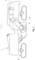
- Fig. 1 shows a construction machine 1 in the form of a large milling machine.
- the construction machine 1 can also be any other construction machine with a drive train in which a clutch is arranged.
- the construction machine 1 shown has chassis 2 which carry a machine frame 4.
- a work roll 6 is stored as a working device for processing a floor covering 3.
- the work roll 6 can have milling bits (not shown) on the lateral surface of the work roll 6 for processing the floor covering 3.
- the machine frame 4 can be height-adjustable via the chassis 2.
- the undercarriages can be wheels or tracked units.
- the construction machine 1 can also have a conveyor device, not shown, for transporting away the milled material.
- the drive train 8 drives the work roll 6.
- the drive train 8 has at least one clutch 14.
- the construction machine 1 can be a milling machine, in particular a road milling machine, a recycler or stabilizer or a surface miner.
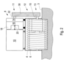
- Fig. 2 shows schematically a cross section through a construction machine 1 with a work roll 6, which is mounted in a machine frame 4.
- the work roll 6 can be mounted in a roll housing, which in turn is firmly connected to the machine frame 4.
- the work roll 6 can also be mounted movably, in particular in a height-adjustable manner, relative to the machine frame 4.
- the work roll 6 can consist, for example, of a milling drum.
- the drive train 8 is shown.
- the drive unit 10 is shown. This can preferably have an internal combustion engine.
- the internal combustion engine can in particular be a diesel engine.
- the drive unit 10 can be coupled via an articulated coupling device, for example an elastomer coupling 20, to a pump distribution gear 16 for driving hydraulic units, for example hydraulic pumps 18.
- the elastomer coupling 20 can also be arranged elsewhere within the drive train 8.
- the drive train 8 has a clutch 14, which is arranged in the drive train 8 between the drive unit 10 and the work roll 6.
- the clutch 14 is a device for switching the torque.
- a traction mechanism 12 for the mechanical drive of the work roll 6 is arranged between the clutch 14 and the work roll 6.
- the traction mechanism 12 has a drive element 11 which is coupled in a rotationally fixed manner to an output shaft 22 of the clutch 14.
- the traction mechanism 12 has an output element 13 which is coupled in a rotationally fixed manner to a drive shaft 15 of the work roll 6.
- a gear, in particular a planetary gear, can also be arranged between the drive shaft 15 and the work roll 6.
- the traction mechanism 12 is preferably a belt drive, the drive and output elements consisting of pulleys 11, 13 over which at least one drive belt 30 rotates.
- the traction mechanism 12 can consist, for example, of a chain drive, in which case the drive and output elements consist of pinions.
- the drive unit 10 or the pump distribution gear 16 can be coupled to the pulley 11 via the clutch 14.
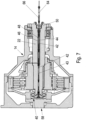
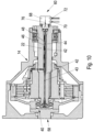
- the clutch 14 is shown in more detail.
- the clutch 14 is preferably a hydraulic clutch.
- the clutch 14 has a drive-side end 58 and an output-side end 60.
- an output shaft 22 is provided, with a drive-side bearing 40 for the output shaft 22 being arranged at the drive-side end.
- a lubricant line 42 is provided for lubricating the drive-side bearing 40, which leads from the output-side end 60 to the drive-side bearing 40 and runs at least in sections through the output shaft 22.
- the lubricant line runs concentrically in the output shaft 22.
- the lubricant line 42 could also run eccentrically to the output shaft 22.
- the hydraulic clutch 14 shown also has a hydraulic line 48 for switching the clutch 14.
- This hydraulic line 48 runs at least partially within the output shaft 22.
- the hydraulic line 48 runs in particular concentrically in the output shaft 22.
- the lubricant line 42 runs at least partially in the hydraulic line 48.
- the first part 46 of the lubricant line 42 runs in the hydraulic line 48 in this case.
- a rod-shaped device 44 is provided for this purpose, which runs within the hydraulic line 48 and in which the first part 46 of the lubricant line 42 is arranged is.
- the output end 60 of the lubricant line 42 is closed by a cover element 56.
- the cover element 56 is removable in a maintenance state, so that in this case the lubricant line 42 can be connected to a lubricant supply.
- the cover element 56 is designed as a rotary feedthrough, which has a passage for hydraulic fluid for the hydraulic line 48.
- the hydraulic line 48 can then be connected to a hydraulic supply through the cover element.
- Fig. 4 the rod-shaped device 44 is shown in more detail.
- This has a head part 50 which is arranged at one end of the rod-shaped device 44.
- a rod-shaped element 45 adjoins the head part 50.
- the lubricant line 42 or the first part 46 of the lubricant line runs through the rod-shaped element 45 and the head part 50.
- the head part 50 has additional passages 54 for the hydraulic fluid.
- a thread 52 which can be screwed into the second part 43 of the lubricant line 42.
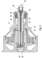
- Fig. 5 shows the clutch 14 in the operating state.
- the cover element 56 which is a rotary feedthrough in the exemplary embodiment shown, conducts hydraulic fluid through the rotary feedthrough and through the head part 50 of the rod-shaped device 44 into the hydraulic line 48 during operation.
- the hydraulic clutch 14 can be switched using the hydraulic fluid.
- the direction of flow of the hydraulic fluid is marked with arrows 62.
- the hydraulic line 48 is closed by the rod-shaped device 44, which is screwed into the second part 43 at this end with the thread 52.
- the hydraulic line 48 and the lubricant line 42 are separated from each other so that no hydraulic fluid can get into the lubricant line 42 and no lubricant can get into the hydraulic line 48.
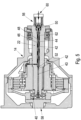
- a maintenance status of the clutch 14 is shown.
- the cover element 56 is removed.
- the lubricant line 42 can be connected to a lubricant supply 64.
- the hydraulic clutch 14 does not need to be supplied with hydraulic fluid. Therefore, the cover element 56 can be removed.
- Fig. 7 the flow direction of the lubricant is shown with the arrows 66.
- the lubricant can be guided to the drive-side bearing 40.
- Fig. 8 alternative embodiment is shown. It is similar to the exemplary embodiment from the previous figures. very similar, but with the difference that a double rotary feedthrough 68 is arranged instead of the cover element 56. This has at least one passage 70 to the lubricant line 42 and at least one passage 72 to the hydraulic line 48.
- the double rotary feedthrough 68 has the advantage that the drive-side bearing 40 can also be lubricated during operation. Both hydraulic fluid and lubricant can therefore be fed through the double rotary feedthrough without having to remove the double rotary feedthrough 68, which acts as a cover. In this way, the lubrication of the drive-side bearing can take place automatically according to a predetermined schedule without having to interrupt operation.
- Fig. 9 shows how the lubricant runs through the double rotary union to the drive side bearing.
- the flow direction of the lubricant is marked 74.
- Fig. 10 shows how the hydraulic fluid runs through the double rotary union 68.
- the direction of flow of the hydraulic fluid is marked with arrows 76.
Landscapes
- Engineering & Computer Science (AREA)
- General Engineering & Computer Science (AREA)
- Mechanical Engineering (AREA)
- Civil Engineering (AREA)
- Structural Engineering (AREA)
- Mining & Mineral Resources (AREA)
- Architecture (AREA)
- Physics & Mathematics (AREA)
- Fluid Mechanics (AREA)
- General Details Of Gearings (AREA)
- Mechanical Operated Clutches (AREA)
- Soil Working Implements (AREA)
Claims (12)
- Engin de chantier (1), avec une chaîne cinématique dans laquelle est disposé un embrayage (14), l'embrayage (14) comprenant :- une extrémité (58) côté entraînement et une extrémité (60) côté sortie,- un arbre de sortie (22), un palier (40) côté entraînement étant disposé sur l'arbre de sortie (22) à l'extrémité (58) côté entraînement,- l'embrayage (14) étant un embrayage hydraulique, une conduite hydraulique (48) pour l'engagement de l'embrayage (14) étant située au moins partiellement à l'intérieur de l'arbre de sortie (22),caractérisé en ce
qu'il est prévu une conduite de lubrifiant (42) destinée à la lubrification du palier (40) côté entraînement, conduite qui conduit de l'extrémité (60) côté sortie vers le palier (40) côté entraînement et traverse au moins par tronçons l'arbre de sortie (22). - Engin de chantier selon la revendication 1, caractérisé en ce que la conduite de lubrifiant (42) est située au moins par tronçons de façon concentrique dans l'arbre de sortie (22).
- Engin de chantier selon la revendication 1 ou 2, caractérisé en ce que la conduite de lubrifiant est située au moins par tronçons de façon excentrée dans l'arbre de sortie (22).
- Engin de chantier selon l'une des revendications 1 à 3, caractérisé en ce que la conduite hydraulique (48) est située au moins par tronçons de façon concentrique dans l'arbre de sortie (22).
- Engin de chantier selon l'une des revendications 1 à 4, caractérisé en ce que la conduite de lubrifiant (42) est située au moins partiellement dans la conduite hydraulique (48).
- Engin de chantier selon l'une des revendications 1 à 5, caractérisé en ce que la conduite de lubrifiant (42) est située au moins par tronçons de façon concentrique rapport à la conduite hydraulique (48).
- Engin de chantier selon l'une des revendications 1 à 6, caractérisé en ce que la conduite de lubrifiant (42) présente une première partie (46) qui est disposée à l'intérieur d'un dispositif (44) en forme de barre qui est quant à lui situé dans la conduite hydraulique (48).
- Engin de chantier selon la revendication 7, caractérisé en ce que le dispositif (44) en forme de barre présente en plus des traversées (54) pour le liquide hydraulique.
- Engin de chantier selon l'une des revendications 1 à 8, caractérisé en ce que l'extrémité (60) côté sortie de la conduite de lubrifiant (42) est terminée par un élément de couverture (56), l'élément de couverture (56) pouvant être enlevé dans un état de maintenance de l'embrayage (14), et la conduite de lubrifiant (42) pouvant être raccordée à une unité d'alimentation en lubrifiant (64).
- Engin de chantier selon la revendication 9, caractérisé en ce que l'élément de couverture (56) est constitué en tant que passage tournant et présente une traversée vers la conduite hydraulique (48) de sorte que, dans l'état de fonctionnement de l'embrayage (14), la conduite hydraulique (48) est raccordée par l'élément de couverture (56) à une alimentation hydraulique.
- Engin de chantier selon l'une des revendications 1 à 8, caractérisé en ce que l'extrémité (60) côté sortie de la conduite de lubrifiant est terminée par un double passage tournant (68), le double passage tournant (68) présentant au moins une traversée vers la conduite de lubrifiant (42) et au moins une traversée vers la conduite hydraulique (48).
- Engin de chantier selon la revendication 11, caractérisé en ce que la lubrification s'effectue automatiquement selon un horaire prédéfini.
Applications Claiming Priority (1)
| Application Number | Priority Date | Filing Date | Title |
|---|---|---|---|
| DE102017214939.6A DE102017214939A1 (de) | 2017-08-25 | 2017-08-25 | Schaltkupplung für eine Baumaschine |
Publications (3)
| Publication Number | Publication Date |
|---|---|
| EP3447323A1 EP3447323A1 (fr) | 2019-02-27 |
| EP3447323C0 EP3447323C0 (fr) | 2023-09-27 |
| EP3447323B1 true EP3447323B1 (fr) | 2023-09-27 |
Family
ID=63165252
Family Applications (1)
| Application Number | Title | Priority Date | Filing Date |
|---|---|---|---|
| EP18187464.5A Active EP3447323B1 (fr) | 2017-08-25 | 2018-08-06 | Embrayage pour un engin de chantier |
Country Status (4)
| Country | Link |
|---|---|
| US (1) | US10900198B2 (fr) |
| EP (1) | EP3447323B1 (fr) |
| CN (3) | CN109423946A (fr) |
| DE (1) | DE102017214939A1 (fr) |
Families Citing this family (1)
| Publication number | Priority date | Publication date | Assignee | Title |
|---|---|---|---|---|
| DE102017214939A1 (de) * | 2017-08-25 | 2019-02-28 | Wirtgen Gmbh | Schaltkupplung für eine Baumaschine |
Citations (2)
| Publication number | Priority date | Publication date | Assignee | Title |
|---|---|---|---|---|
| EP0324152A1 (fr) * | 1988-01-15 | 1989-07-19 | Deere & Company | Embrayage à fluide |
| EP1875004A1 (fr) * | 2005-04-15 | 2008-01-09 | Wirtgen GmbH Machinenbau | Engin de chantier, notamment machine a fraiser la chaussee, recycleur ou stabilisateur et chaine cinematique pour ce type d'engins de chantier |
Family Cites Families (23)
| Publication number | Priority date | Publication date | Assignee | Title |
|---|---|---|---|---|
| US2838913A (en) * | 1950-07-15 | 1958-06-17 | Gen Motors Corp | Aircraft power system and clutch control therefor |
| US2924983A (en) * | 1956-06-14 | 1960-02-16 | Danly Mach Specialties Inc | Dual speed clutch assembly |
| FR1196177A (fr) * | 1958-05-20 | 1959-11-23 | Embrayage pneumatique pour machines-outils | |
| GB1018539A (en) | 1963-10-04 | 1966-01-26 | Ford Motor Co | Automatic change-speed transmission |
| US3463283A (en) * | 1966-01-06 | 1969-08-26 | Int Harvester Co | Hydraulic pressure control system for clutches |
| US3823802A (en) * | 1972-08-18 | 1974-07-16 | Caterpillar Tractor Co | Clutch with controlled coolant flow |
| US3833100A (en) * | 1973-01-02 | 1974-09-03 | Twin Disc Inc | Control system for a power transmission clutch |
| US4899861A (en) * | 1987-03-16 | 1990-02-13 | Rockford Powertrain, Inc. | Variable speed drive for engine cooling fans |
| US5009118A (en) * | 1990-03-30 | 1991-04-23 | General Motors Corporation | Power transmission with parallel identical countershafts |
| HU216712B (hu) * | 1994-02-24 | 1999-08-30 | RÁBA Magyar Vagon- és Gépgyár Rt. | Speciális olajkeringető rendszer, főként nedvesfékes munkagépfutóművek és nagy terhelésű kerékagy-bolygóműves futóművek hűtésére |
| US5495927A (en) * | 1994-06-24 | 1996-03-05 | General Motors Corporation | Controlled cooling apparatus for torque transfer devices |
| US5577588A (en) * | 1995-03-17 | 1996-11-26 | General Motors Corporation | Lube assembly for a transmission friction device |
| JPH1030651A (ja) * | 1996-07-16 | 1998-02-03 | Nsk Warner Kk | 発進クラッチの油圧回路 |
| DE19642305A1 (de) * | 1996-10-14 | 1998-04-16 | Zahnradfabrik Friedrichshafen | Schaltbare Kupplung |
| US6701241B2 (en) * | 2000-09-15 | 2004-03-02 | Robert Bosch Gmbh | Method and device for operating a clutch |
| US20080121488A1 (en) * | 2006-11-27 | 2008-05-29 | Tomoyuki Miyazaki | Starting clutch |
| DE202007010294U1 (de) * | 2007-07-20 | 2008-11-27 | Wirtgen Gmbh | Baumaschine sowie Schaltkupplung zum Schalten des Kraftflusses |
| US7938147B2 (en) * | 2008-11-05 | 2011-05-10 | Allison Transmission, Inc. | Apparatus and method for axially transferring fluids to a plurality of components |
| AU2011317308B2 (en) * | 2010-10-19 | 2016-11-03 | Allison Transmission, Inc. | Face spline clutch |
| MX338570B (es) * | 2012-03-05 | 2016-04-22 | Muncie Power Prod Inc | Aparatos y metodos de lubricacion de toma de fuerza. |
| GB201218234D0 (en) * | 2012-10-11 | 2012-11-28 | Agco Int Gmbh | PTO drivelines |
| US10132366B1 (en) * | 2014-06-06 | 2018-11-20 | Logan Clutch Corporation | Clutch assembly and system |
| DE102017214939A1 (de) * | 2017-08-25 | 2019-02-28 | Wirtgen Gmbh | Schaltkupplung für eine Baumaschine |
-
2017
- 2017-08-25 DE DE102017214939.6A patent/DE102017214939A1/de not_active Withdrawn
-
2018
- 2018-08-06 EP EP18187464.5A patent/EP3447323B1/fr active Active
- 2018-08-21 US US16/106,465 patent/US10900198B2/en active Active
- 2018-08-22 CN CN201810963033.4A patent/CN109423946A/zh active Pending
- 2018-08-22 CN CN202610131653.6A patent/CN121630970A/zh active Pending
- 2018-08-22 CN CN201821358079.5U patent/CN209227338U/zh active Active
Patent Citations (2)
| Publication number | Priority date | Publication date | Assignee | Title |
|---|---|---|---|---|
| EP0324152A1 (fr) * | 1988-01-15 | 1989-07-19 | Deere & Company | Embrayage à fluide |
| EP1875004A1 (fr) * | 2005-04-15 | 2008-01-09 | Wirtgen GmbH Machinenbau | Engin de chantier, notamment machine a fraiser la chaussee, recycleur ou stabilisateur et chaine cinematique pour ce type d'engins de chantier |
Also Published As
| Publication number | Publication date |
|---|---|
| EP3447323A1 (fr) | 2019-02-27 |
| EP3447323C0 (fr) | 2023-09-27 |
| US20190063038A1 (en) | 2019-02-28 |
| DE102017214939A1 (de) | 2019-02-28 |
| US10900198B2 (en) | 2021-01-26 |
| CN121630970A (zh) | 2026-03-10 |
| CN109423946A (zh) | 2019-03-05 |
| CN209227338U (zh) | 2019-08-09 |
Similar Documents
| Publication | Publication Date | Title |
|---|---|---|
| DE102007019202B4 (de) | Selbstfahrende Baumaschine, inbesondere Straßenfräsmaschine, Recycler oder Stabilisierer | |
| DE4238256C2 (de) | Zapfenwellengetriebe mit einer Schmiereinrichtung | |
| DE3028490C2 (de) | Stufenlos einstellbares Kegelscheibengetriebe | |
| DE102012024770B4 (de) | Selbstfahrende Baumaschine | |
| DE102012024104A1 (de) | Verdichtungsmaschine | |
| DE112013007520T5 (de) | Getriebeanordnung und Verfahren zur Steuerung einer Getriebeanordnung | |
| DE1949973C3 (de) | Hydrostatisches Aggregat | |
| EP3447323B1 (fr) | Embrayage pour un engin de chantier | |
| DE3317829A1 (de) | Schmiereinrichtung fuer einen bohrstangenschaft in einer schlagbohrmaschine | |
| EP3365497B1 (fr) | Dispositif d'entraînement pour engin de chantier, et engin de chantier | |
| DE102020131788A1 (de) | Hydrauliksystem mit Niederdruckpumpenbypassschaltung | |
| EP0045867B2 (fr) | Système régulateur pour un compresseur pour service dans des véhicules automobiles | |
| WO2015066822A1 (fr) | Unité de transmission et ensemble pour une presse à découper | |
| DE102004032227A1 (de) | Schmierungsstruktur eines Handschaltgetriebes | |
| EP3289244B1 (fr) | Engin de travail à repartition de puissance | |
| DE2519115A1 (de) | Getriebe | |
| DE102014108007B4 (de) | Wellenflansch einer landwirtschaftlichen Erntemaschine | |
| DE3033939A1 (de) | Keilriemenscheibe mit veraenderlicher geschwindigkeit | |
| DE102014203435A1 (de) | Ölpumpenantrieb | |
| EP3215762B1 (fr) | Dispositif d'entraînement pour véhicule automobile | |
| DE2553010A1 (de) | Fahrzeuggetriebe | |
| DE102022205091B3 (de) | Getriebe und Antriebsstrang | |
| DE102024200485B3 (de) | Getriebeanordnung sowie Antriebsstrang mit einer solchen Getriebeanordnung | |
| DE202011051421U1 (de) | Antriebsvorrichtung einer Schneckenzentrifuge | |
| DE4308113A1 (de) | Antriebsanordnung für Nebenaggregate |
Legal Events
| Date | Code | Title | Description |
|---|---|---|---|
| PUAI | Public reference made under article 153(3) epc to a published international application that has entered the european phase |
Free format text: ORIGINAL CODE: 0009012 |
|
| STAA | Information on the status of an ep patent application or granted ep patent |
Free format text: STATUS: THE APPLICATION HAS BEEN PUBLISHED |
|
| AK | Designated contracting states |
Kind code of ref document: A1 Designated state(s): AL AT BE BG CH CY CZ DE DK EE ES FI FR GB GR HR HU IE IS IT LI LT LU LV MC MK MT NL NO PL PT RO RS SE SI SK SM TR |
|
| AX | Request for extension of the european patent |
Extension state: BA ME |
|
| STAA | Information on the status of an ep patent application or granted ep patent |
Free format text: STATUS: REQUEST FOR EXAMINATION WAS MADE |
|
| 17P | Request for examination filed |
Effective date: 20190827 |
|
| RBV | Designated contracting states (corrected) |
Designated state(s): AL AT BE BG CH CY CZ DE DK EE ES FI FR GB GR HR HU IE IS IT LI LT LU LV MC MK MT NL NO PL PT RO RS SE SI SK SM TR |
|
| STAA | Information on the status of an ep patent application or granted ep patent |
Free format text: STATUS: EXAMINATION IS IN PROGRESS |
|
| 17Q | First examination report despatched |
Effective date: 20191115 |
|
| GRAP | Despatch of communication of intention to grant a patent |
Free format text: ORIGINAL CODE: EPIDOSNIGR1 |
|
| STAA | Information on the status of an ep patent application or granted ep patent |
Free format text: STATUS: GRANT OF PATENT IS INTENDED |
|
| INTG | Intention to grant announced |
Effective date: 20230327 |
|
| P01 | Opt-out of the competence of the unified patent court (upc) registered |
Effective date: 20230527 |
|
| GRAS | Grant fee paid |
Free format text: ORIGINAL CODE: EPIDOSNIGR3 |
|
| GRAA | (expected) grant |
Free format text: ORIGINAL CODE: 0009210 |
|
| STAA | Information on the status of an ep patent application or granted ep patent |
Free format text: STATUS: THE PATENT HAS BEEN GRANTED |
|
| AK | Designated contracting states |
Kind code of ref document: B1 Designated state(s): AL AT BE BG CH CY CZ DE DK EE ES FI FR GB GR HR HU IE IS IT LI LT LU LV MC MK MT NL NO PL PT RO RS SE SI SK SM TR |
|
| REG | Reference to a national code |
Ref country code: GB Ref legal event code: FG4D Free format text: NOT ENGLISH |
|
| REG | Reference to a national code |
Ref country code: CH Ref legal event code: EP |
|
| REG | Reference to a national code |
Ref country code: DE Ref legal event code: R096 Ref document number: 502018013308 Country of ref document: DE |
|
| REG | Reference to a national code |
Ref country code: IE Ref legal event code: FG4D Free format text: LANGUAGE OF EP DOCUMENT: GERMAN |
|
| P04 | Withdrawal of opt-out of the competence of the unified patent court (upc) registered |
Effective date: 20231030 |
|
| U01 | Request for unitary effect filed |
Effective date: 20231027 |
|
| U07 | Unitary effect registered |
Designated state(s): AT BE BG DE DK EE FI FR IT LT LU LV MT NL PT SE SI Effective date: 20231102 |
|
| PG25 | Lapsed in a contracting state [announced via postgrant information from national office to epo] |
Ref country code: GR Free format text: LAPSE BECAUSE OF FAILURE TO SUBMIT A TRANSLATION OF THE DESCRIPTION OR TO PAY THE FEE WITHIN THE PRESCRIBED TIME-LIMIT Effective date: 20231228 |
|
| PG25 | Lapsed in a contracting state [announced via postgrant information from national office to epo] |
Ref country code: RS Free format text: LAPSE BECAUSE OF FAILURE TO SUBMIT A TRANSLATION OF THE DESCRIPTION OR TO PAY THE FEE WITHIN THE PRESCRIBED TIME-LIMIT Effective date: 20230927 Ref country code: NO Free format text: LAPSE BECAUSE OF FAILURE TO SUBMIT A TRANSLATION OF THE DESCRIPTION OR TO PAY THE FEE WITHIN THE PRESCRIBED TIME-LIMIT Effective date: 20231227 Ref country code: HR Free format text: LAPSE BECAUSE OF FAILURE TO SUBMIT A TRANSLATION OF THE DESCRIPTION OR TO PAY THE FEE WITHIN THE PRESCRIBED TIME-LIMIT Effective date: 20230927 Ref country code: GR Free format text: LAPSE BECAUSE OF FAILURE TO SUBMIT A TRANSLATION OF THE DESCRIPTION OR TO PAY THE FEE WITHIN THE PRESCRIBED TIME-LIMIT Effective date: 20231228 |
|
| PG25 | Lapsed in a contracting state [announced via postgrant information from national office to epo] |
Ref country code: IS Free format text: LAPSE BECAUSE OF FAILURE TO SUBMIT A TRANSLATION OF THE DESCRIPTION OR TO PAY THE FEE WITHIN THE PRESCRIBED TIME-LIMIT Effective date: 20240127 |
|
| PG25 | Lapsed in a contracting state [announced via postgrant information from national office to epo] |
Ref country code: ES Free format text: LAPSE BECAUSE OF FAILURE TO SUBMIT A TRANSLATION OF THE DESCRIPTION OR TO PAY THE FEE WITHIN THE PRESCRIBED TIME-LIMIT Effective date: 20230927 |
|
| PG25 | Lapsed in a contracting state [announced via postgrant information from national office to epo] |
Ref country code: SM Free format text: LAPSE BECAUSE OF FAILURE TO SUBMIT A TRANSLATION OF THE DESCRIPTION OR TO PAY THE FEE WITHIN THE PRESCRIBED TIME-LIMIT Effective date: 20230927 Ref country code: RO Free format text: LAPSE BECAUSE OF FAILURE TO SUBMIT A TRANSLATION OF THE DESCRIPTION OR TO PAY THE FEE WITHIN THE PRESCRIBED TIME-LIMIT Effective date: 20230927 Ref country code: IS Free format text: LAPSE BECAUSE OF FAILURE TO SUBMIT A TRANSLATION OF THE DESCRIPTION OR TO PAY THE FEE WITHIN THE PRESCRIBED TIME-LIMIT Effective date: 20240127 Ref country code: ES Free format text: LAPSE BECAUSE OF FAILURE TO SUBMIT A TRANSLATION OF THE DESCRIPTION OR TO PAY THE FEE WITHIN THE PRESCRIBED TIME-LIMIT Effective date: 20230927 Ref country code: CZ Free format text: LAPSE BECAUSE OF FAILURE TO SUBMIT A TRANSLATION OF THE DESCRIPTION OR TO PAY THE FEE WITHIN THE PRESCRIBED TIME-LIMIT Effective date: 20230927 Ref country code: SK Free format text: LAPSE BECAUSE OF FAILURE TO SUBMIT A TRANSLATION OF THE DESCRIPTION OR TO PAY THE FEE WITHIN THE PRESCRIBED TIME-LIMIT Effective date: 20230927 |
|
| PG25 | Lapsed in a contracting state [announced via postgrant information from national office to epo] |
Ref country code: PL Free format text: LAPSE BECAUSE OF FAILURE TO SUBMIT A TRANSLATION OF THE DESCRIPTION OR TO PAY THE FEE WITHIN THE PRESCRIBED TIME-LIMIT Effective date: 20230927 |
|
| REG | Reference to a national code |
Ref country code: DE Ref legal event code: R097 Ref document number: 502018013308 Country of ref document: DE |
|
| PLBE | No opposition filed within time limit |
Free format text: ORIGINAL CODE: 0009261 |
|
| STAA | Information on the status of an ep patent application or granted ep patent |
Free format text: STATUS: NO OPPOSITION FILED WITHIN TIME LIMIT |
|
| 26N | No opposition filed |
Effective date: 20240628 |
|
| U20 | Renewal fee for the european patent with unitary effect paid |
Year of fee payment: 7 Effective date: 20240814 |
|
| P05 | Withdrawal of opt-out of the competence of the unified patent court (upc) changed |
Free format text: CASE NUMBER: APP_584236/2023 Effective date: 20231102 |
|
| REG | Reference to a national code |
Ref country code: CH Ref legal event code: PL |
|
| GBPC | Gb: european patent ceased through non-payment of renewal fee |
Effective date: 20240806 |
|
| PG25 | Lapsed in a contracting state [announced via postgrant information from national office to epo] |
Ref country code: CH Free format text: LAPSE BECAUSE OF NON-PAYMENT OF DUE FEES Effective date: 20240831 Ref country code: MC Free format text: LAPSE BECAUSE OF FAILURE TO SUBMIT A TRANSLATION OF THE DESCRIPTION OR TO PAY THE FEE WITHIN THE PRESCRIBED TIME-LIMIT Effective date: 20230927 |
|
| PG25 | Lapsed in a contracting state [announced via postgrant information from national office to epo] |
Ref country code: GB Free format text: LAPSE BECAUSE OF NON-PAYMENT OF DUE FEES Effective date: 20240806 |
|
| PG25 | Lapsed in a contracting state [announced via postgrant information from national office to epo] |
Ref country code: IE Free format text: LAPSE BECAUSE OF NON-PAYMENT OF DUE FEES Effective date: 20240806 |
|
| U20 | Renewal fee for the european patent with unitary effect paid |
Year of fee payment: 8 Effective date: 20250826 |
|
| PG25 | Lapsed in a contracting state [announced via postgrant information from national office to epo] |
Ref country code: CY Free format text: LAPSE BECAUSE OF FAILURE TO SUBMIT A TRANSLATION OF THE DESCRIPTION OR TO PAY THE FEE WITHIN THE PRESCRIBED TIME-LIMIT; INVALID AB INITIO Effective date: 20180806 |
|
| PG25 | Lapsed in a contracting state [announced via postgrant information from national office to epo] |
Ref country code: HU Free format text: LAPSE BECAUSE OF FAILURE TO SUBMIT A TRANSLATION OF THE DESCRIPTION OR TO PAY THE FEE WITHIN THE PRESCRIBED TIME-LIMIT; INVALID AB INITIO Effective date: 20180806 |