EP3447348B1 - Entlüftungskanal für ein servoventil - Google Patents
Entlüftungskanal für ein servoventil Download PDFInfo
- Publication number
- EP3447348B1 EP3447348B1 EP17461596.3A EP17461596A EP3447348B1 EP 3447348 B1 EP3447348 B1 EP 3447348B1 EP 17461596 A EP17461596 A EP 17461596A EP 3447348 B1 EP3447348 B1 EP 3447348B1
- Authority
- EP
- European Patent Office
- Prior art keywords
- cover
- plane
- path
- hydraulic valve
- venting passage
- Prior art date
- Legal status (The legal status is an assumption and is not a legal conclusion. Google has not performed a legal analysis and makes no representation as to the accuracy of the status listed.)
- Active
Links
Images


Classifications
-
- F—MECHANICAL ENGINEERING; LIGHTING; HEATING; WEAPONS; BLASTING
- F16—ENGINEERING ELEMENTS AND UNITS; GENERAL MEASURES FOR PRODUCING AND MAINTAINING EFFECTIVE FUNCTIONING OF MACHINES OR INSTALLATIONS; THERMAL INSULATION IN GENERAL
- F16K—VALVES; TAPS; COCKS; ACTUATING-FLOATS; DEVICES FOR VENTING OR AERATING
- F16K24/00—Devices, e.g. valves, for venting or aerating enclosures
- F16K24/02—Devices, e.g. valves, for venting or aerating enclosures the enclosure being itself a valve, tap, or cock
-
- F—MECHANICAL ENGINEERING; LIGHTING; HEATING; WEAPONS; BLASTING
- F16—ENGINEERING ELEMENTS AND UNITS; GENERAL MEASURES FOR PRODUCING AND MAINTAINING EFFECTIVE FUNCTIONING OF MACHINES OR INSTALLATIONS; THERMAL INSULATION IN GENERAL
- F16K—VALVES; TAPS; COCKS; ACTUATING-FLOATS; DEVICES FOR VENTING OR AERATING
- F16K17/00—Safety valves; Equalising valves, e.g. pressure relief valves
- F16K17/20—Excess-flow valves
- F16K17/22—Excess-flow valves actuated by the difference of pressure between two places in the flow line
- F16K17/32—Excess-flow valves actuated by the difference of pressure between two places in the flow line acting on a servo-mechanism or on a catch-releasing mechanism
-
- F—MECHANICAL ENGINEERING; LIGHTING; HEATING; WEAPONS; BLASTING
- F16—ENGINEERING ELEMENTS AND UNITS; GENERAL MEASURES FOR PRODUCING AND MAINTAINING EFFECTIVE FUNCTIONING OF MACHINES OR INSTALLATIONS; THERMAL INSULATION IN GENERAL
- F16K—VALVES; TAPS; COCKS; ACTUATING-FLOATS; DEVICES FOR VENTING OR AERATING
- F16K21/00—Fluid-delivery valves, e.g. self-closing valves
- F16K21/02—Fluid-delivery valves, e.g. self-closing valves providing a continuous small flow
-
- F—MECHANICAL ENGINEERING; LIGHTING; HEATING; WEAPONS; BLASTING
- F16—ENGINEERING ELEMENTS AND UNITS; GENERAL MEASURES FOR PRODUCING AND MAINTAINING EFFECTIVE FUNCTIONING OF MACHINES OR INSTALLATIONS; THERMAL INSULATION IN GENERAL
- F16K—VALVES; TAPS; COCKS; ACTUATING-FLOATS; DEVICES FOR VENTING OR AERATING
- F16K27/00—Construction of housing; Use of materials therefor
- F16K27/12—Covers for housings
-
- F—MECHANICAL ENGINEERING; LIGHTING; HEATING; WEAPONS; BLASTING
- F16—ENGINEERING ELEMENTS AND UNITS; GENERAL MEASURES FOR PRODUCING AND MAINTAINING EFFECTIVE FUNCTIONING OF MACHINES OR INSTALLATIONS; THERMAL INSULATION IN GENERAL
- F16K—VALVES; TAPS; COCKS; ACTUATING-FLOATS; DEVICES FOR VENTING OR AERATING
- F16K31/00—Actuating devices; Operating means; Releasing devices
- F16K31/02—Actuating devices; Operating means; Releasing devices electric; magnetic
- F16K31/06—Actuating devices; Operating means; Releasing devices electric; magnetic using a magnet, e.g. diaphragm valves, cutting off by means of a liquid
-
- F—MECHANICAL ENGINEERING; LIGHTING; HEATING; WEAPONS; BLASTING
- F15—FLUID-PRESSURE ACTUATORS; HYDRAULICS OR PNEUMATICS IN GENERAL
- F15B—SYSTEMS ACTING BY MEANS OF FLUIDS IN GENERAL; FLUID-PRESSURE ACTUATORS, e.g. SERVOMOTORS; DETAILS OF FLUID-PRESSURE SYSTEMS, NOT OTHERWISE PROVIDED FOR
- F15B21/00—Common features of fluid actuator systems; Fluid-pressure actuator systems or details thereof, not covered by any other group of this subclass
- F15B21/04—Special measures taken in connection with the properties of the fluid
- F15B21/044—Removal or measurement of undissolved gas, e.g. de-aeration, venting or bleeding
-
- F—MECHANICAL ENGINEERING; LIGHTING; HEATING; WEAPONS; BLASTING
- F16—ENGINEERING ELEMENTS AND UNITS; GENERAL MEASURES FOR PRODUCING AND MAINTAINING EFFECTIVE FUNCTIONING OF MACHINES OR INSTALLATIONS; THERMAL INSULATION IN GENERAL
- F16K—VALVES; TAPS; COCKS; ACTUATING-FLOATS; DEVICES FOR VENTING OR AERATING
- F16K24/00—Devices, e.g. valves, for venting or aerating enclosures
- F16K24/04—Devices, e.g. valves, for venting or aerating enclosures for venting only
Definitions
- the present disclosure relates to venting passages, and servovalves including such venting passages.
- Venting passages are used, for example in hydraulic valves such as servovalves, to allow condensed water or other liquid, such as that formed by vapour condensation, to exit the valve.
- US 2005/0217740 discloses a solenoid valve having an inlet/outlet passage forming a labyrinth.
- US 2015/0144820 discloses a solenoid valve having a spiral-like, undulated outlet.
- DE 10 2008 012702 discloses a ventilation device having a labyrinth valve.
- the present disclosure provides a hydraulic valve comprising a venting passage for allowing fluidic communication between an interior and an exterior of the hydraulic valve, the venting passage having a first portion following a first path extending in a first plane, and a second portion following a second path extending in a second plane, wherein the first plane is at an angle to the second plane, and wherein the first and second paths are labyrinth paths in their respective planes.
- the venting passage may allow gas, condensation or other fluid to escape from the interior of the valve. It may also allow any pressure differential between the interior and exterior of the hydraulic valve, such as a pressure differential created by taking the hydraulic valve to altitude, to equalise.
- the valve may be a servovalve.
- venting passage When a hydraulic valve, such as a servovalve, is exposed to a severe environment, such as one having a high level of dustiness, the venting passage may allow contaminants such as sand to enter the interior of the servovalve.
- the venting passage of the present disclosure extends over two planes and includes at least a portion in each plane having a labyrinth path, which may prevent or inhibit contaminants from entering the valve.
- the first and/or second portions of the path may be enclosed.
- the first portion meets the second portion at a location where the first and second planes meet, and the angle is an angle between the first and second planes at said location.
- the normal to the first plane is at an angle to the normal to the second plane.
- the planes being "at an angle" to one another refers to an angle which is not equal to 0° or 180°.
- the angle may be from about 60° to about 120°, or from about 80° to about 100°, or about 90°.
- the first path extending in the first plane may extend in any direction within the first plane.
- the first path and the second path may both be labyrinth paths in their respective planes.
- The, or each, labyrinth path comprises at least one change in angle within the plane.
- Each respective path thus extends in a first direction and a second direction, wherein the first direction is different to the second direction.
- the path must therefore bend between the first direction and the second direction, defining the change in angle.
- the direction of each path corresponds to that of the longitudinal axis of the path (defined when travelling from one end of the path to the other end of the path).
- the labyrinth path may be a serpentine path having at least one, at least two, at least three, or more than three turns. Each turn may change the path direction by 90°, 180°, from about 10° to about 180°, from about 30° to about 150°, from about 60° to about 120°, or from about 80° to about 100°.
- the first and/or second path may be a labyrinth path that longitudinally extends in a first direction, a second direction, and a third direction of the respective path.
- the first direction may be substantially opposite to the third direction.
- the path may extend in the first direction, have a bend, such as a 90° bend, then extend in the second direction, then have another bend, such as a 90° bend in the same direction to complete a 180° total angular change, then extend in the third direction, the third direction being substantially opposite to the first direction.
- the length of the path extending in the first direction may therefore be parallel to the length of the path extending in the third direction. Both of these lengths of path may be perpendicular to the length of path extending in the second direction.
- Other bend angles are contemplated, resulting in the length of path extending in the first direction not being parallel to the length of path extending in the third direction.
- first and third directions which may or may not be opposite to one another (i.e. the length of path extending in the first direction may or may not be parallel to the length of path extending in the third direction.
- the first and/or second path may comprise a U-shaped portion or a z-shaped portion.
- the first and/or second path may include a 180° bend.
- the hydraulic valve may comprise a body and a cover covering at least a part of the body, wherein the venting passage is located between and defined by the body and the cover.
- the venting passage may be partially defined by a channel in the body and/or partially defined by a channel in the cover.
- the body may have a housing portion and a base portion, wherein an exterior surface of the housing portion extends in the first plane, and an exterior surface of the base portion extends in the second plane.
- the cover may have a housing portion and a flange portion, and an interior surface of the cover housing portion is in the first plane, and an interior surface of the flange portion is in the second plane.
- At least one of the first and second planes may be a curved plane.
- the curved plane may be a cylindrical plane.
- At least one of the first and second planes may be a flat plane.
- One of the first and second planes may be a curved plane, and the other of the first and second planes may be a flat plane.
- all lines perpendicular to the curved plane are preferably all at the same angle to a line perpendicular to the flat plane, i.e. the curved plane curves in a direction perpendicular to the flat plane.
- the hydraulic valve may be a servovalve.
- Figures 1 and 2 show an example of a servovalve 10 having a body 12 and a cover 14.
- Figure 1 shows a side view of a portion of the servovalve 10.
- Figure 2 shows a portion of the servovalve 10 of Figure 1 , except with the cover 14 illustrated as translucent so that the portion of the valve under the cover 14 can be seen.
- an exterior surface of the body 12 includes a generally cylindrical first portion 12a, and a base second portion 12b having a larger cross section than the first portion 12a.
- the second portion 12b includes a plurality of holes or ports 20.
- the holes may be used for various purposes, such as for mounting the servovalve to a manifold, or for mounting nozzles or pipes to the servovalve in use.
- the holes or ports may be plugged after a nozzle or pipe has been mounted thereto.
- a channel 22 is formed in the body 12 of the servovalve 10.
- the channel may be formed by any suitable method, such as by engraving.
- a first portion 22a of the channel 22 is formed in the first portion 12a of the body 12.
- a second portion 22b of the channel 22 is formed in the top surface 12c of the second portion 12b of the body 12, i.e. perpendicular to the first portion 22a of the channel 22.
- the cover 14 is located to cover the cylindrical portion 12a of the body 12 of the servovalve 10, and is attached to the body 12 using screws or bolts 18.
- the cover 14 covers and encloses the first portion 22a of the channel, forming a venting passage 16 extending from within the cover 14 to outside of the cover 14.
- the venting passage 16 thus extends between and is defined by the cover 14 and the body 12.
- the venting passage 16 extends from the interior of the cover 14 to the exterior of the cover 14 to allow vapour, condensed vapour, water or other liquid to escape from the interior of the cover 14.
- the cover 14 may cover, for example, a torque motor cavity or may cover another element that changes temperature in use, potentially resulting in condensation within the cover 14.
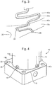
- Figure 3 shows a portion of a body 12 of a servovalve 10 according to an embodiment of the present disclosure, with the cover 14 removed.
- a channel 22 may be located in the body 12 of the servovalve 10.
- the channel 22 may be formed by any suitable method, such as by engraving.
- the body 12 may comprise a first portion 12a and a second portion 12b.
- the first portion 12a may be a housing portion 12a.
- the second portion 12b may be a base portion 12b.
- the first portion 12a may be generally cylindrical, resulting in a surface thereof forming a curved plane.
- the second portion 12b may comprise a flat planar top surface 12c.
- the first and second portions 12a, 12b of the body 12 of the servovalve may be integrally formed.
- a first portion 22a of the channel 22 may be located in the first portion 12a of the body 12.
- the first portion 22a of the channel may thus extend in the curved plane of the first portion 12a of the body 12.
- a second portion 22b of the channel 22 may be located in the second portion 12b of the body 12.
- the second portion may thus extend in a flat plane.
- the first and/or second portions 22a,22b of the channel 22 may be recesses in the exterior surface of the body 12, and may have substantially uniform cross-sections. Each said cross-section may have a substantially flat bottom, may have substantially parallel sides perpendicular to the bottom, and may optionally have a curved corner between the bottom and each of the parallel sides.
- the first and second portions 22a,22b of the channel 22 each have a labyrinth path.
- a labyrinth path is a path which follows a course having at least one bend therein.
- the labyrinth path of each of the first and/or second portion 22a,22b may have multiple bends therein, e.g. ⁇ 2, ⁇ 3, ⁇ 4, ⁇ 5, ⁇ 6, ⁇ 7 ⁇ 8, ⁇ 9, or > 10 bends.
- Each bend may be a substantially right-angle (e.g. 90°) bend, although other angles are contemplated.
- one or more bends may be provided in the first and/or second portion 22a,22b of the channel 22, e.g. to form one or more 180° turn in the path.
- the labyrinth path of the first and/or second portion may extend various directions in the portions of the path between the bends.
- each labyrinth path may extend in a first direction, a second direction, and a third direction, and the first and third directions may be substantially opposite to one another.
- the first portion 22a and the second portion 22b of the channel 22 may meet at the junction between the first and second portions 12a, 12b of the body 12.
- the angle between the curved plane of the first portion 12a and the flat plane of the second portion 12b may be substantially a right-angle (e.g. 90°), although other angles are contemplated.
- Figure 4 shows the servovalve 10 of Fig. 3 , but with the cover 14 over the body 12 so that the channel 22 and cover 14 form a venting passage 16 from the interior to the exterior of the cover 14.
- the cover 14 may comprise a housing portion 14a and a flange portion 14b.
- the housing portion 14a may extend over the generally cylindrical first portion 12a of the body 12.
- the flange portion 14b may extend over the flat top surface 12c of the second portion 12b of the body 12.
- the cover 14 may thus have a "top hat" shape.
- the cover 14 may include apertures 26 to allow any ports or holes 20 in the body 12 to remain accessible.
- FIG. 5 shows a portion of the embodiment of Fig. 4 , but with the cover 14 being translucent (for illustrative purposes only) such that the venting passage 16 may be seen.
- the venting passage 16 extends from the interior of the cover 14 to the exterior of the cover 14. This may allow gas, vapour, or condensed vapour such as water or other liquid to escape from the interior of the cover 14.
- the labyrinth path of the venting passage 16 obstructs the passage for sand, dust and other contaminates into the valve.
- the venting passage 16 helps avoid liquids building up inside the cover 14, without allowing the interior of the cover 14, i.e. the valve, to become contaminated.
- the cover 14 may cover a torque motor cavity (e.g. the portion 12a of the body may be a motor), or may cover another element that changes temperature in use.
- the venting passage 16 avoids such temperature changes causing liquid to build up inside the cover 14 due to, for example, condensation.
- the venting passage 16 is defined by the channel 22 in the body 12 and the cover 14 over it. As the cover 14 extends over the first and second portions 12a, 12b of the body 12, this results in the venting passage 16 extending in two planes, which may be a curved plane and a flat plane respectively (i.e. the surface planes of the body portions 12a, 12b). The planes may be perpendicular to one another.
- a first portion 16a of the venting passage 16 may extend in the curved plane of the first portion 12a of the body 12, and a second portion 16b of the venting passage may extend in the flat plane of the second portion 12b of the body 12.
- the first and second portions 16a,16b of the venting passage 16 may meet at a location where the curved plane and the flat plane meet.
- the angle between the planes at this location may be substantially at a right-angle (e.g. 90°). There may thus be a bend of 90° between the plane in which the first portion 16a and second portion 16b of the venting passage 16 are located.
- channel 22 has been described as being formed in the body 12, it may alternatively, or additionally, be formed by recessing the interior surface of the cover 14.
- valve may be another type of valve (e.g. hydraulic valve), or another apparatus having a body and a cover.
Landscapes
- Engineering & Computer Science (AREA)
- General Engineering & Computer Science (AREA)
- Mechanical Engineering (AREA)
- Sealing Using Fluids, Sealing Without Contact, And Removal Of Oil (AREA)
- Valve Housings (AREA)
Claims (9)
- Hydraulisches Ventil (10), einen Entlüftungskanal (16) umfassend, um eine Fluidverbindung zwischen einem Inneren und einem Äußeren des hydraulischen Ventils (10) zuzulassen, wobei der Entlüftungskanal (16) einen ersten Abschnitt (16a), der einem ersten Pfad folgt, der sich in einer ersten Ebene erstreckt, und einen zweiten Abschnitt (16b) aufweist, der einem zweiten Pfad folgt, der sich in einer zweiten Ebene erstreckt, wobei die erste Ebene in einem Winkel zu der zweiten Ebene steht und wobei der erste und der zweite Pfad in ihrer jeweiligen Ebene Labyrinthpfade sind.
- Hydraulisches Ventil (10) nach Anspruch 1, wobei der Winkel zwischen 60° und 120°, oder zwischen 80° und 100° oder ungefähr 90° beträgt.
- Hydraulisches Ventil (10) nach einem der vorhergehenden Ansprüche, wobei sich der erste und/oder der zweite Pfad longitudinal in eine erste Richtung, eine zweite Richtung und eine dritte Richtung des entsprechenden Pfads erstrecken.
- Hydraulisches Ventil (10) nach Anspruch 3, wobei die erste Richtung der dritten Richtung wesentlich entgegengesetzt ist.
- Hydraulisches Ventil (10) nach einem der vorhergehenden Ansprüche, wobei der erste und/oder der zweite Pfad eine Biegung um 180° beinhalten.
- Hydraulisches Ventil (10) nach einem der vorhergehenden Ansprüche, einen Körper (12) und eine Abdeckung (14) umfassend, die mindestens einen Teil des Körpers (12) abdeckt, wobei sich der Entlüftungskanal (16) zwischen dem Körper (12) und der Abdeckung (14) befindet und durch diese definiert ist.
- Hydraulisches Ventil (10) nach Anspruch 6, wobei der Körper (12) einen Gehäuseabschnitt (12a) und einen Basisabschnitt (12b) aufweist, wobei sich eine äußere Oberfläche des Gehäuseabschnitts (12a) in der ersten Ebene erstreckt und sich eine äußere Oberfläche des Basisabschnitts (12b) in der zweiten Ebene erstreckt.
- Hydraulisches Ventil (10) nach Anspruch 6 oder 7, wobei die Abdeckung (14) einen Gehäuseabschnitt (14a) und einen Flanschabschnitt (14b) aufweist und sich eine innere Oberfläche des Abdeckungsgehäuseabschnitts (14a) in der ersten Ebene befindet und sich eine innere Oberfläche des Flanschabschnitts (14b) in der zweiten Ebene befindet.
- Hydraulisches Ventil (10) nach einem der vorhergehenden Ansprüche, wobei das hydraulische Ventil (10) ein Servoventil (10) ist.
Priority Applications (2)
| Application Number | Priority Date | Filing Date | Title |
|---|---|---|---|
| EP17461596.3A EP3447348B1 (de) | 2017-08-24 | 2017-08-24 | Entlüftungskanal für ein servoventil |
| US16/059,236 US11092256B2 (en) | 2017-08-24 | 2018-08-09 | Venting passage for a servovalve |
Applications Claiming Priority (1)
| Application Number | Priority Date | Filing Date | Title |
|---|---|---|---|
| EP17461596.3A EP3447348B1 (de) | 2017-08-24 | 2017-08-24 | Entlüftungskanal für ein servoventil |
Publications (2)
| Publication Number | Publication Date |
|---|---|
| EP3447348A1 EP3447348A1 (de) | 2019-02-27 |
| EP3447348B1 true EP3447348B1 (de) | 2020-05-27 |
Family
ID=59702659
Family Applications (1)
| Application Number | Title | Priority Date | Filing Date |
|---|---|---|---|
| EP17461596.3A Active EP3447348B1 (de) | 2017-08-24 | 2017-08-24 | Entlüftungskanal für ein servoventil |
Country Status (2)
| Country | Link |
|---|---|
| US (1) | US11092256B2 (de) |
| EP (1) | EP3447348B1 (de) |
Family Cites Families (25)
| Publication number | Priority date | Publication date | Assignee | Title |
|---|---|---|---|---|
| US2063966A (en) | 1934-02-03 | 1936-12-15 | Whitlock Cordage Company | Twine |
| US3791408A (en) * | 1972-05-31 | 1974-02-12 | Yuken Kogyo Co Ltd | Electromagnetic pressure-telecontrolling valve |
| US4310123A (en) * | 1980-07-21 | 1982-01-12 | General Motors Corporation | Electromagnetic fuel injector with adjustable armature spring |
| JPH0277376U (de) * | 1988-12-01 | 1990-06-13 | ||
| US6538543B2 (en) * | 2000-02-24 | 2003-03-25 | Delphi Technologies, Inc. | Particle-impeding and ventilated solenoid actuator |
| DE10112663A1 (de) * | 2001-03-16 | 2002-09-19 | Bosch Gmbh Robert | Ventil mit Filter |
| JP4829419B2 (ja) * | 2001-04-06 | 2011-12-07 | 株式会社不二工機 | 可変容量型圧縮機用制御弁 |
| JP4413504B2 (ja) * | 2003-02-13 | 2010-02-10 | 株式会社東芝 | 医用画像処理装置、医用画像処理方法および医用画像処理プログラム |
| JP4089588B2 (ja) * | 2003-02-13 | 2008-05-28 | 株式会社ジェイテクト | 電磁弁 |
| DE10336009A1 (de) * | 2003-08-01 | 2005-02-24 | Oberhofer Werkzeugbau Gmbh | Schaumdrossel |
| JP2005282754A (ja) * | 2004-03-30 | 2005-10-13 | Toyoda Mach Works Ltd | 電磁弁 |
| DE102004042352B4 (de) * | 2004-08-20 | 2007-08-09 | Siemens Ag | Kraftstoffinjektor für eine Brennkraftmaschine |
| EP1628016B1 (de) * | 2004-08-20 | 2008-04-23 | VDO Automotive AG | Stellantrieb für einen Kraftstoffinjektor einer Brennkraftmaschine |
| US7909053B2 (en) * | 2005-02-04 | 2011-03-22 | Emerson Process Management Valve Automation, Inc. | Draining system for valve actuator/valve stem protector assemblies |
| US20070131281A1 (en) * | 2005-12-13 | 2007-06-14 | Delaware Capital Formation, Inc. | Underground fuel tank vent valve |
| DE102006029966B4 (de) * | 2006-06-29 | 2010-04-22 | Continental Automotive Gmbh | Abdichtungsanordnung eines Piezoaktors für ein Kraftstoffeinspritzventil einer Brennkraftmaschine |
| DE102008012702B4 (de) * | 2008-03-05 | 2013-04-25 | Knorr-Bremse Systeme für Nutzfahrzeuge GmbH | Entlüftungsvorrichtung für Gehäuse |
| DE102008037076A1 (de) * | 2008-07-23 | 2010-01-28 | Schaeffler Kg | Elektromagnetische Stelleinheit eines hydraulischen Wegeventils |
| WO2010088108A2 (en) * | 2009-01-27 | 2010-08-05 | Borgwarner Inc. | Open end variable bleed solenoid (vbs) valve with inherent viscous dampening |
| WO2011052371A1 (ja) * | 2009-10-30 | 2011-05-05 | イーグル工業株式会社 | ソレノイドバルブ |
| KR101158423B1 (ko) * | 2010-05-26 | 2012-06-22 | 주식회사 케피코 | 차량의 자동변속기용 유압 솔레노이드 밸브 |
| US9016663B2 (en) * | 2012-02-22 | 2015-04-28 | Delphi Technologies, Inc. | Solenoid-actuated pressure control valve |
| KR102008824B1 (ko) * | 2012-06-21 | 2019-08-08 | 보르그워너 인코퍼레이티드 | 침지형 솔레노이드 밸브 |
| JP6075764B2 (ja) * | 2013-03-22 | 2017-02-08 | サンデンホールディングス株式会社 | 制御弁及びこの制御弁を備えた可変容量圧縮機 |
| GB2577436B (en) * | 2017-06-20 | 2024-11-27 | Control Components | Multi-stage, multi-path rotary disc valve |
-
2017
- 2017-08-24 EP EP17461596.3A patent/EP3447348B1/de active Active
-
2018
- 2018-08-09 US US16/059,236 patent/US11092256B2/en active Active
Non-Patent Citations (1)
| Title |
|---|
| None * |
Also Published As
| Publication number | Publication date |
|---|---|
| US20190063629A1 (en) | 2019-02-28 |
| EP3447348A1 (de) | 2019-02-27 |
| US11092256B2 (en) | 2021-08-17 |
Similar Documents
| Publication | Publication Date | Title |
|---|---|---|
| CN111779724B (zh) | 一种航空电静液作动系统用液压集成阀块 | |
| EP2966327B1 (de) | Verbesserte dreiwegeventilstruktur | |
| JP6320824B2 (ja) | ガス供給管、およびガス処理装置 | |
| CN107270004B (zh) | 流路形成结构体 | |
| CN203309329U (zh) | 用于加压管道的减压器和用于加压管道的阀组件 | |
| CN105179779A (zh) | 用于数字的阀定位器的排放组件和方法 | |
| US11703135B2 (en) | Multi-port coolant flow control valve assembly | |
| US11988290B2 (en) | Coolant flow control valve | |
| US20160265672A1 (en) | Diverter valve | |
| US20170153070A1 (en) | Connection device for heat exchanger and heat exchanger provided with said connection device | |
| JP6355730B2 (ja) | 熱交換器 | |
| ATE405780T1 (de) | Ventile für doppelwändige leitungen, wie treibstoffleitungen für flugzeuge, und damit verbundene systeme und verfahren | |
| US11092256B2 (en) | Venting passage for a servovalve | |
| US8757046B2 (en) | Piston with a duct under a gasket | |
| EP1548345A1 (de) | Kugelventil mit Geräuschdämpfer | |
| KR102678239B1 (ko) | 노이즈 저감 슬리브 및 전자 팽창 밸브 | |
| US20190145539A1 (en) | Atmosphere control manifold | |
| CN120265908A (zh) | 使用阀内件中的分流路径来减轻阀噪声 | |
| CN120202369A (zh) | 加热阀体 | |
| US6672566B2 (en) | Multi-use sterile access/GMP diaphragm valve housing | |
| CN112088279A (zh) | 用于分配空气的设备 | |
| JP7397470B2 (ja) | 流体制御装置 | |
| US6296016B1 (en) | Double obturator valve | |
| US7901191B1 (en) | Enclosure with fluid inducement chamber | |
| EP4303522A1 (de) | Luftansaugdämpfer |
Legal Events
| Date | Code | Title | Description |
|---|---|---|---|
| PUAI | Public reference made under article 153(3) epc to a published international application that has entered the european phase |
Free format text: ORIGINAL CODE: 0009012 |
|
| STAA | Information on the status of an ep patent application or granted ep patent |
Free format text: STATUS: THE APPLICATION HAS BEEN PUBLISHED |
|
| AK | Designated contracting states |
Kind code of ref document: A1 Designated state(s): AL AT BE BG CH CY CZ DE DK EE ES FI FR GB GR HR HU IE IS IT LI LT LU LV MC MK MT NL NO PL PT RO RS SE SI SK SM TR |
|
| AX | Request for extension of the european patent |
Extension state: BA ME |
|
| STAA | Information on the status of an ep patent application or granted ep patent |
Free format text: STATUS: REQUEST FOR EXAMINATION WAS MADE |
|
| 17P | Request for examination filed |
Effective date: 20190827 |
|
| RBV | Designated contracting states (corrected) |
Designated state(s): AL AT BE BG CH CY CZ DE DK EE ES FI FR GB GR HR HU IE IS IT LI LT LU LV MC MK MT NL NO PL PT RO RS SE SI SK SM TR |
|
| GRAP | Despatch of communication of intention to grant a patent |
Free format text: ORIGINAL CODE: EPIDOSNIGR1 |
|
| RIC1 | Information provided on ipc code assigned before grant |
Ipc: F16K 24/02 20060101AFI20191028BHEP Ipc: F16K 27/12 20060101ALI20191028BHEP Ipc: F16T 1/34 20060101ALI20191028BHEP Ipc: F15B 21/044 20190101ALI20191028BHEP |
|
| STAA | Information on the status of an ep patent application or granted ep patent |
Free format text: STATUS: GRANT OF PATENT IS INTENDED |
|
| INTG | Intention to grant announced |
Effective date: 20191205 |
|
| GRAS | Grant fee paid |
Free format text: ORIGINAL CODE: EPIDOSNIGR3 |
|
| GRAA | (expected) grant |
Free format text: ORIGINAL CODE: 0009210 |
|
| STAA | Information on the status of an ep patent application or granted ep patent |
Free format text: STATUS: THE PATENT HAS BEEN GRANTED |
|
| AK | Designated contracting states |
Kind code of ref document: B1 Designated state(s): AL AT BE BG CH CY CZ DE DK EE ES FI FR GB GR HR HU IE IS IT LI LT LU LV MC MK MT NL NO PL PT RO RS SE SI SK SM TR |
|
| REG | Reference to a national code |
Ref country code: GB Ref legal event code: FG4D |
|
| REG | Reference to a national code |
Ref country code: CH Ref legal event code: EP |
|
| REG | Reference to a national code |
Ref country code: AT Ref legal event code: REF Ref document number: 1274900 Country of ref document: AT Kind code of ref document: T Effective date: 20200615 |
|
| REG | Reference to a national code |
Ref country code: DE Ref legal event code: R096 Ref document number: 602017017255 Country of ref document: DE |
|
| REG | Reference to a national code |
Ref country code: LT Ref legal event code: MG4D |
|
| PG25 | Lapsed in a contracting state [announced via postgrant information from national office to epo] |
Ref country code: FI Free format text: LAPSE BECAUSE OF FAILURE TO SUBMIT A TRANSLATION OF THE DESCRIPTION OR TO PAY THE FEE WITHIN THE PRESCRIBED TIME-LIMIT Effective date: 20200527 Ref country code: GR Free format text: LAPSE BECAUSE OF FAILURE TO SUBMIT A TRANSLATION OF THE DESCRIPTION OR TO PAY THE FEE WITHIN THE PRESCRIBED TIME-LIMIT Effective date: 20200828 Ref country code: NO Free format text: LAPSE BECAUSE OF FAILURE TO SUBMIT A TRANSLATION OF THE DESCRIPTION OR TO PAY THE FEE WITHIN THE PRESCRIBED TIME-LIMIT Effective date: 20200827 Ref country code: PT Free format text: LAPSE BECAUSE OF FAILURE TO SUBMIT A TRANSLATION OF THE DESCRIPTION OR TO PAY THE FEE WITHIN THE PRESCRIBED TIME-LIMIT Effective date: 20200928 Ref country code: LT Free format text: LAPSE BECAUSE OF FAILURE TO SUBMIT A TRANSLATION OF THE DESCRIPTION OR TO PAY THE FEE WITHIN THE PRESCRIBED TIME-LIMIT Effective date: 20200527 Ref country code: SE Free format text: LAPSE BECAUSE OF FAILURE TO SUBMIT A TRANSLATION OF THE DESCRIPTION OR TO PAY THE FEE WITHIN THE PRESCRIBED TIME-LIMIT Effective date: 20200527 Ref country code: IS Free format text: LAPSE BECAUSE OF FAILURE TO SUBMIT A TRANSLATION OF THE DESCRIPTION OR TO PAY THE FEE WITHIN THE PRESCRIBED TIME-LIMIT Effective date: 20200927 |
|
| REG | Reference to a national code |
Ref country code: NL Ref legal event code: MP Effective date: 20200527 |
|
| PG25 | Lapsed in a contracting state [announced via postgrant information from national office to epo] |
Ref country code: HR Free format text: LAPSE BECAUSE OF FAILURE TO SUBMIT A TRANSLATION OF THE DESCRIPTION OR TO PAY THE FEE WITHIN THE PRESCRIBED TIME-LIMIT Effective date: 20200527 Ref country code: LV Free format text: LAPSE BECAUSE OF FAILURE TO SUBMIT A TRANSLATION OF THE DESCRIPTION OR TO PAY THE FEE WITHIN THE PRESCRIBED TIME-LIMIT Effective date: 20200527 Ref country code: RS Free format text: LAPSE BECAUSE OF FAILURE TO SUBMIT A TRANSLATION OF THE DESCRIPTION OR TO PAY THE FEE WITHIN THE PRESCRIBED TIME-LIMIT Effective date: 20200527 Ref country code: BG Free format text: LAPSE BECAUSE OF FAILURE TO SUBMIT A TRANSLATION OF THE DESCRIPTION OR TO PAY THE FEE WITHIN THE PRESCRIBED TIME-LIMIT Effective date: 20200827 |
|
| REG | Reference to a national code |
Ref country code: AT Ref legal event code: MK05 Ref document number: 1274900 Country of ref document: AT Kind code of ref document: T Effective date: 20200527 |
|
| PG25 | Lapsed in a contracting state [announced via postgrant information from national office to epo] |
Ref country code: AL Free format text: LAPSE BECAUSE OF FAILURE TO SUBMIT A TRANSLATION OF THE DESCRIPTION OR TO PAY THE FEE WITHIN THE PRESCRIBED TIME-LIMIT Effective date: 20200527 Ref country code: NL Free format text: LAPSE BECAUSE OF FAILURE TO SUBMIT A TRANSLATION OF THE DESCRIPTION OR TO PAY THE FEE WITHIN THE PRESCRIBED TIME-LIMIT Effective date: 20200527 |
|
| PG25 | Lapsed in a contracting state [announced via postgrant information from national office to epo] |
Ref country code: ES Free format text: LAPSE BECAUSE OF FAILURE TO SUBMIT A TRANSLATION OF THE DESCRIPTION OR TO PAY THE FEE WITHIN THE PRESCRIBED TIME-LIMIT Effective date: 20200527 Ref country code: AT Free format text: LAPSE BECAUSE OF FAILURE TO SUBMIT A TRANSLATION OF THE DESCRIPTION OR TO PAY THE FEE WITHIN THE PRESCRIBED TIME-LIMIT Effective date: 20200527 Ref country code: CZ Free format text: LAPSE BECAUSE OF FAILURE TO SUBMIT A TRANSLATION OF THE DESCRIPTION OR TO PAY THE FEE WITHIN THE PRESCRIBED TIME-LIMIT Effective date: 20200527 Ref country code: RO Free format text: LAPSE BECAUSE OF FAILURE TO SUBMIT A TRANSLATION OF THE DESCRIPTION OR TO PAY THE FEE WITHIN THE PRESCRIBED TIME-LIMIT Effective date: 20200527 Ref country code: SM Free format text: LAPSE BECAUSE OF FAILURE TO SUBMIT A TRANSLATION OF THE DESCRIPTION OR TO PAY THE FEE WITHIN THE PRESCRIBED TIME-LIMIT Effective date: 20200527 Ref country code: IT Free format text: LAPSE BECAUSE OF FAILURE TO SUBMIT A TRANSLATION OF THE DESCRIPTION OR TO PAY THE FEE WITHIN THE PRESCRIBED TIME-LIMIT Effective date: 20200527 Ref country code: EE Free format text: LAPSE BECAUSE OF FAILURE TO SUBMIT A TRANSLATION OF THE DESCRIPTION OR TO PAY THE FEE WITHIN THE PRESCRIBED TIME-LIMIT Effective date: 20200527 Ref country code: DK Free format text: LAPSE BECAUSE OF FAILURE TO SUBMIT A TRANSLATION OF THE DESCRIPTION OR TO PAY THE FEE WITHIN THE PRESCRIBED TIME-LIMIT Effective date: 20200527 |
|
| PG25 | Lapsed in a contracting state [announced via postgrant information from national office to epo] |
Ref country code: SK Free format text: LAPSE BECAUSE OF FAILURE TO SUBMIT A TRANSLATION OF THE DESCRIPTION OR TO PAY THE FEE WITHIN THE PRESCRIBED TIME-LIMIT Effective date: 20200527 Ref country code: PL Free format text: LAPSE BECAUSE OF FAILURE TO SUBMIT A TRANSLATION OF THE DESCRIPTION OR TO PAY THE FEE WITHIN THE PRESCRIBED TIME-LIMIT Effective date: 20200527 |
|
| REG | Reference to a national code |
Ref country code: DE Ref legal event code: R097 Ref document number: 602017017255 Country of ref document: DE |
|
| PG25 | Lapsed in a contracting state [announced via postgrant information from national office to epo] |
Ref country code: MC Free format text: LAPSE BECAUSE OF FAILURE TO SUBMIT A TRANSLATION OF THE DESCRIPTION OR TO PAY THE FEE WITHIN THE PRESCRIBED TIME-LIMIT Effective date: 20200527 |
|
| REG | Reference to a national code |
Ref country code: CH Ref legal event code: PL |
|
| PLBE | No opposition filed within time limit |
Free format text: ORIGINAL CODE: 0009261 |
|
| STAA | Information on the status of an ep patent application or granted ep patent |
Free format text: STATUS: NO OPPOSITION FILED WITHIN TIME LIMIT |
|
| PG25 | Lapsed in a contracting state [announced via postgrant information from national office to epo] |
Ref country code: CH Free format text: LAPSE BECAUSE OF NON-PAYMENT OF DUE FEES Effective date: 20200831 Ref country code: LI Free format text: LAPSE BECAUSE OF NON-PAYMENT OF DUE FEES Effective date: 20200831 Ref country code: LU Free format text: LAPSE BECAUSE OF NON-PAYMENT OF DUE FEES Effective date: 20200824 |
|
| 26N | No opposition filed |
Effective date: 20210302 |
|
| REG | Reference to a national code |
Ref country code: BE Ref legal event code: MM Effective date: 20200831 |
|
| PG25 | Lapsed in a contracting state [announced via postgrant information from national office to epo] |
Ref country code: SI Free format text: LAPSE BECAUSE OF FAILURE TO SUBMIT A TRANSLATION OF THE DESCRIPTION OR TO PAY THE FEE WITHIN THE PRESCRIBED TIME-LIMIT Effective date: 20200527 |
|
| PG25 | Lapsed in a contracting state [announced via postgrant information from national office to epo] |
Ref country code: BE Free format text: LAPSE BECAUSE OF NON-PAYMENT OF DUE FEES Effective date: 20200831 Ref country code: IE Free format text: LAPSE BECAUSE OF NON-PAYMENT OF DUE FEES Effective date: 20200824 |
|
| PG25 | Lapsed in a contracting state [announced via postgrant information from national office to epo] |
Ref country code: TR Free format text: LAPSE BECAUSE OF FAILURE TO SUBMIT A TRANSLATION OF THE DESCRIPTION OR TO PAY THE FEE WITHIN THE PRESCRIBED TIME-LIMIT Effective date: 20200527 Ref country code: MT Free format text: LAPSE BECAUSE OF FAILURE TO SUBMIT A TRANSLATION OF THE DESCRIPTION OR TO PAY THE FEE WITHIN THE PRESCRIBED TIME-LIMIT Effective date: 20200527 Ref country code: CY Free format text: LAPSE BECAUSE OF FAILURE TO SUBMIT A TRANSLATION OF THE DESCRIPTION OR TO PAY THE FEE WITHIN THE PRESCRIBED TIME-LIMIT Effective date: 20200527 |
|
| PG25 | Lapsed in a contracting state [announced via postgrant information from national office to epo] |
Ref country code: MK Free format text: LAPSE BECAUSE OF FAILURE TO SUBMIT A TRANSLATION OF THE DESCRIPTION OR TO PAY THE FEE WITHIN THE PRESCRIBED TIME-LIMIT Effective date: 20200527 |
|
| P01 | Opt-out of the competence of the unified patent court (upc) registered |
Effective date: 20230522 |
|
| PGFP | Annual fee paid to national office [announced via postgrant information from national office to epo] |
Ref country code: DE Payment date: 20250724 Year of fee payment: 9 |
|
| PGFP | Annual fee paid to national office [announced via postgrant information from national office to epo] |
Ref country code: GB Payment date: 20250725 Year of fee payment: 9 |
|
| PGFP | Annual fee paid to national office [announced via postgrant information from national office to epo] |
Ref country code: FR Payment date: 20250725 Year of fee payment: 9 |