EP3447350B1 - Thermostat et système de régulation de température - Google Patents
Thermostat et système de régulation de température Download PDFInfo
- Publication number
- EP3447350B1 EP3447350B1 EP17785354.6A EP17785354A EP3447350B1 EP 3447350 B1 EP3447350 B1 EP 3447350B1 EP 17785354 A EP17785354 A EP 17785354A EP 3447350 B1 EP3447350 B1 EP 3447350B1
- Authority
- EP
- European Patent Office
- Prior art keywords
- valve
- port
- chamber
- seat
- spring
- Prior art date
- Legal status (The legal status is an assumption and is not a legal conclusion. Google has not performed a legal analysis and makes no representation as to the accuracy of the status listed.)
- Active
Links
Images








Classifications
-
- F—MECHANICAL ENGINEERING; LIGHTING; HEATING; WEAPONS; BLASTING
- F16—ENGINEERING ELEMENTS AND UNITS; GENERAL MEASURES FOR PRODUCING AND MAINTAINING EFFECTIVE FUNCTIONING OF MACHINES OR INSTALLATIONS; THERMAL INSULATION IN GENERAL
- F16K—VALVES; TAPS; COCKS; ACTUATING-FLOATS; DEVICES FOR VENTING OR AERATING
- F16K31/00—Actuating devices; Operating means; Releasing devices
- F16K31/002—Actuating devices; Operating means; Releasing devices actuated by temperature variation
-
- F—MECHANICAL ENGINEERING; LIGHTING; HEATING; WEAPONS; BLASTING
- F01—MACHINES OR ENGINES IN GENERAL; ENGINE PLANTS IN GENERAL; STEAM ENGINES
- F01P—COOLING OF MACHINES OR ENGINES IN GENERAL; COOLING OF INTERNAL-COMBUSTION ENGINES
- F01P7/00—Controlling of coolant flow
- F01P7/14—Controlling of coolant flow the coolant being liquid
- F01P7/16—Controlling of coolant flow the coolant being liquid by thermostatic control
-
- F—MECHANICAL ENGINEERING; LIGHTING; HEATING; WEAPONS; BLASTING
- F01—MACHINES OR ENGINES IN GENERAL; ENGINE PLANTS IN GENERAL; STEAM ENGINES
- F01P—COOLING OF MACHINES OR ENGINES IN GENERAL; COOLING OF INTERNAL-COMBUSTION ENGINES
- F01P11/00—Component parts, details, or accessories not provided for in, or of interest apart from, groups F01P1/00 - F01P9/00
- F01P11/08—Arrangements of lubricant coolers
-
- F—MECHANICAL ENGINEERING; LIGHTING; HEATING; WEAPONS; BLASTING
- F16—ENGINEERING ELEMENTS AND UNITS; GENERAL MEASURES FOR PRODUCING AND MAINTAINING EFFECTIVE FUNCTIONING OF MACHINES OR INSTALLATIONS; THERMAL INSULATION IN GENERAL
- F16H—GEARING
- F16H57/00—General details of gearing
- F16H57/04—Features relating to lubrication or cooling or heating
- F16H57/0412—Cooling or heating; Control of temperature
- F16H57/0413—Controlled cooling or heating of lubricant; Temperature control therefor
-
- F—MECHANICAL ENGINEERING; LIGHTING; HEATING; WEAPONS; BLASTING
- F16—ENGINEERING ELEMENTS AND UNITS; GENERAL MEASURES FOR PRODUCING AND MAINTAINING EFFECTIVE FUNCTIONING OF MACHINES OR INSTALLATIONS; THERMAL INSULATION IN GENERAL
- F16K—VALVES; TAPS; COCKS; ACTUATING-FLOATS; DEVICES FOR VENTING OR AERATING
- F16K1/00—Lift valves or globe valves, i.e. cut-off apparatus with closure members having at least a component of their opening and closing motion perpendicular to the closing faces
- F16K1/32—Details
- F16K1/34—Cutting-off parts, e.g. valve members, seats
-
- F—MECHANICAL ENGINEERING; LIGHTING; HEATING; WEAPONS; BLASTING
- F16—ENGINEERING ELEMENTS AND UNITS; GENERAL MEASURES FOR PRODUCING AND MAINTAINING EFFECTIVE FUNCTIONING OF MACHINES OR INSTALLATIONS; THERMAL INSULATION IN GENERAL
- F16K—VALVES; TAPS; COCKS; ACTUATING-FLOATS; DEVICES FOR VENTING OR AERATING
- F16K11/00—Multiple-way valves, e.g. mixing valves; Pipe fittings incorporating such valves
- F16K11/02—Multiple-way valves, e.g. mixing valves; Pipe fittings incorporating such valves with all movable sealing faces moving as one unit
- F16K11/04—Multiple-way valves, e.g. mixing valves; Pipe fittings incorporating such valves with all movable sealing faces moving as one unit comprising only lift valves
- F16K11/044—Multiple-way valves, e.g. mixing valves; Pipe fittings incorporating such valves with all movable sealing faces moving as one unit comprising only lift valves with movable valve members positioned between valve seats
-
- F—MECHANICAL ENGINEERING; LIGHTING; HEATING; WEAPONS; BLASTING
- F16—ENGINEERING ELEMENTS AND UNITS; GENERAL MEASURES FOR PRODUCING AND MAINTAINING EFFECTIVE FUNCTIONING OF MACHINES OR INSTALLATIONS; THERMAL INSULATION IN GENERAL
- F16K—VALVES; TAPS; COCKS; ACTUATING-FLOATS; DEVICES FOR VENTING OR AERATING
- F16K27/00—Construction of housing; Use of materials therefor
- F16K27/02—Construction of housing; Use of materials therefor of lift valves
-
- G—PHYSICS
- G05—CONTROLLING; REGULATING
- G05D—SYSTEMS FOR CONTROLLING OR REGULATING NON-ELECTRIC VARIABLES
- G05D23/00—Control of temperature
- G05D23/01—Control of temperature without auxiliary power
- G05D23/02—Control of temperature without auxiliary power with sensing element expanding and contracting in response to changes of temperature
- G05D23/024—Control of temperature without auxiliary power with sensing element expanding and contracting in response to changes of temperature the sensing element being of the rod type, tube type, or of a similar type
- G05D23/025—Control of temperature without auxiliary power with sensing element expanding and contracting in response to changes of temperature the sensing element being of the rod type, tube type, or of a similar type the sensing element being placed within a regulating fluid flow
Definitions
- the present application relates to the field of fluid control, and in particular to a thermostatic valve and a temperature control system
- a thermostatic valve is shown in WO2014/082474 A1 .
- lubricating oil When a vehicle is running, various components need to be lubricated timely by lubricating oil, to ensure normal operation of the vehicle. If the lubricating oil does not have a good lubricating property, a service life of the vehicle may be adversely affected.
- the lubricating property of the lubricating oil has a great relationship with the temperature of the lubricating oil. When the temperature of the lubricating oil is excessively high or excessively low, the lubricating property of the lubricating oil may be adversely affected.
- the lubricating oil generally may not have a too high temperature when the vehicle is normally running. In the case that the vehicle is overloaded or is set in a four-wheel drive mode to run in snow or run cross country, the vehicle is running in a state that a hydraulic torque converter slips excessively, which may cause the temperature of a transmission oil to be excessively high, thus degrading the lubricating property.
- the function of adjusting the temperature of the gearbox oil is mainly achieved by a temperature control flow passage constituted by a thermostatic valve and an external heat exchanging device for cooling.
- a temperature control flow passage constituted by a thermostatic valve and an external heat exchanging device for cooling.
- a heat sensitive material of a thermal actuator expands due to being heated, and thus a passage for the gearbox oil to directly flow back to the gearbox is closed or a flow rate of the passage is decreased, and the oil with a high temperature enters into the external heat exchanging device for cooling, and then the cooled oil flows back to the gearbox.
- the technical solution of the present application is to provide a thermostatic valve with a relatively simple structure, such that the thermal actuator of the thermostatic valve is not shaken heavily even if the pressure of the fluid is high during an operation of the thermostatic valve.
- a thermostatic valve which includes a valve body in which a chamber is provided, an end cap assembly, a thermal actuator and a first spring mounted in the chamber.
- the valve body is provided with at least three ports for communicating with outside, the three ports include a first port, a second port and a third port.
- the thermal actuator includes a valve rod and a body portion.
- the chamber includes a first chamber and a second chamber, the second chamber is smaller than the first chamber, and the second chamber is away from the end cap assembly relative to the first chamber.
- the first port is in communication with the first chamber, the third port is in communication with the second chamber, and the first spring is partially or totally located in the second chamber.
- the thermal actuator is mostly or totally located in the first chamber, the first chamber is larger than the thermal actuator.
- the thermostatic valve is further provided with a guide portion in the chamber.
- the thermal actuator includes a guide fitting portion fitting with the guide portion, and the guide portion is slidably fitted with the guide fitting portion.
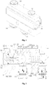
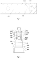
- Figure 1 to Figure 7 are respectively schematic diagrams according to an embodiment.
- Figure 1 is a schematic perspective view of the thermostatic valve.
- Figure 2 is a schematic sectional view of the thermostatic valve in an operating state.
- Figure 3 is a schematic sectional view of the thermostatic valve in another operating state.
- Figure 4 is a schematic partially enlarged view of Figure 2 .
- Figure 5 is a schematic partially enlarged view of Figure 3 .
- Figure 6a and Figure 6b are respectively a schematic perspective view and a schematic sectional view of an end cap of the thermostatic valve.
- Figure 7 is a schematic sectional view of the valve body in the embodiment.
- An initial deformation force described in this specification refers to a pressure acting on an elastic element, which is in a compressed condition when a product is not used, in the case that an external force acts on the elastic element and the elastic element tends to deform.
- the locality terms such as "top”, “bottom”, “left”, “right” described in this specification are each defined according to respective locality relationship determined taking the end cap assembly as an upper side and taking a center axis of a chamber of the thermostatic valve as a center or respective locality relationship in the drawings.
- the thermostatic valve includes a valve body 1 within which a chamber 10 is provided and a thermal actuator 2 mounted in the chamber 10.
- the thermostatic valve further includes a first spring 31 and an end cap assembly.
- the valve body 1 is provided with at least three ports for communicating with the outside.
- the three ports include a first port 11, a second port 12 and a third port 13.
- An end of the chamber 10 is open, and this open end 100 is configured to arrange the end cap assembly.
- the other end of the valve body opposite to the end cap assembly is not provided with any opening, such that the processing process of the valve body may be simplified.
- the first spring 31 is first assembled into the chamber 10, and the thermal actuator 2 is assembled into the chamber 10 through the open end 100 of the chamber 10, and then the end cap assembly is assembled into the open end 100 of the chamber 10.
- the end cap assembly and the valve body are arranged relatively fixedly.
- a second retainer ring 51 is clamped in a groove of the open end 100 to achieve a position limitation in one direction, such that the end cap assembly cannot move outwards to disengage.
- the end cap assembly is limited by a step portion of the open end, such that the end cap assembly cannot further move into the chamber, thereby achieving a relative fixing.
- the thermal actuator 2 is arranged in the chamber 10 and abuts against the first spring 31 through the end cap assembly.
- the chamber 10 includes a first chamber 101 and a second chamber 102.
- the second chamber 102 is smaller than the first chamber 101 so as to form a step portion therebetween.
- the step portion serves as a first valve seat 15 of the thermostatic valve and forms a first valve port 150.
- the first chamber 101 is larger than the thermal actuator 2, and the phrase "the first chamber is larger than the thermal actuator" herein means that each portion of the first chamber fitting with the thermal actuator is larger than a corresponding portion of the thermal actuator, such that the thermal actuator may move within a certain range in the chamber, that is, a moving stroke of the thermal actuator, and it is not necessary that all portions of the entire first chamber are larger than any portion of the thermal actuator.
- the first port 11 and the second port 12 are in communication with the first chamber 101.
- An axial position of the first port 11 in communication with the first chamber 101 is different from an axial position of the second port 12 in communication with the first chamber 101.
- the valve body 1 is further provided with a third chamber 103 with an axial direction different from the axial direction of the chamber 10.
- the axial direction of the third chamber is substantially perpendicular to the axial direction of the chamber 10.
- the third port 13 is in communication with the second chamber 102 through the third chamber 103.
- the valve body further includes a fourth port 14 in communication with the outside.
- the fourth port 13 is arranged opposite to the third port 14.
- the fourth port 13 and the third port 14 may also be arranged at the same side, which just may increase a height of the valve body. In other cases, the fourth port 13 and the third port 14 may also be arranged on two adjacent sides, respectively. Both the fourth port 13 and the third port 14 are in communication with the third chamber 103.
- the first port 11 and the second port 12 may be arranged at opposite positions of the valve body and may be arranged at different positions in the axial direction.
- the fourth port 13 and the third port 14 may be arranged at opposite positions of the valve body, and the first port 11 is arranged at the same side as one of the fourth port 13 and the third port 14, and the second port 12 is arranged at the same side as the other one of the fourth port 13 and the third port 14. It is to be noted that the fourth port 14 may not be arranged, the purpose of arranging the fourth port 14 is only to facilitate the connection and mounting of pipelines of the thermostatic valve.
- the thermal actuator 2 includes a body 22 of the thermal actuator, a valve rod 24 and a heat sensitive material filled in the thermal actuator.
- the volume of the heat sensitive material may change with a change of the temperature, and the volume of the heat sensitive material changes to push the valve rod to move, such that the valve rod is urged to move relative to the body of the thermal actuator.
- the body 22 further includes a first outer wall portion 23. In this embodiment, the first outer wall portion serves as a second valve core.
- the thermal actuator 2 further includes a first valve core 21 relatively fixed on the body 22 of the thermal actuator. The first valve core 21 is arranged opposite to the first valve port 150 or toward the first valve port 150.
- the thermal actuator 2 is further provided with a first outer wall portion 23 on the other side opposite to the first valve core 21.
- the first outer wall portion 23 is relatively close to the valve rod 24.
- the end cap assembly is further provided with a second valve seat 16.
- a through hole of the second valve seat 16 forms a second valve port 160.
- the first outer wall portion 23 includes a second valve core 231 on a side relatively close to the valve rod that may be used to block the second valve port 160.
- the second valve core 231 is relatively fitted with the second valve port.
- the first valve core 21 may be formed integrally with the body 22, and may also be arranged on the body 22 in a fixed manner, for example, in a manner of tight fitting and position-limiting, or for example, a limiting step is provided on the body to prevent the first valve core 21 from moving toward the first outer wall portion.
- the end cap assembly includes an end cap 4, a spring seat 54, a first retainer ring 52 and a second spring 32.
- the end cap 4 is provided with an accommodating chamber 401.
- the second spring 32 is located in the accommodating chamber 401, and the first retainer ring 52 is retained in a groove of the accommodating chamber.
- the spring seat 54 is limited to the accommodating chamber 401 by the first retainer ring 52.
- One end of the second spring 32 abuts against the accommodating chamber 401, and the other end of the second spring 32 abuts against the spring seat 54.
- the spring seat has a cap-like structure.
- the spring seat is sleeved on an end portion at the top of the valve rod 24, and the end portion at the top of the valve rod 24 extending into the spring seat is located in an inner chamber of the spring seat.
- the end of the second spring 32 abutting against the spring seat 54 abuts against an outer extension of the spring seat.
- the second spring 32 is in a compressed state.
- An initial deformation force of the second spring 32 is greater than an initial deformation force of the first spring 31, and the initial deformation force of the second spring 32 is greater than an elastic force generated by the deformation of the first spring 31 when the thermal actuator contacts and shuts off the first valve port.
- the end cap assembly includes a body portion 41, a valve seat portion 44, a guide portion 46, a second connection portion 45 and a first connection portion 43.
- the body portion is provided with a groove 411 at the outer side for arranging a sealing member, such that the body portion of the end cap assembly is fitted with the open end 100 of the chamber 10 for seal.
- At least one groove 411 for arranging the sealing member may be arranged on the outer circumferential side of the body portion 41 of the end cap, and the accommodating chamber 401 for placing the second spring is arranged inside the body portion 41 of the end cap. In this way, after the end cap assembly is fitted with the valve body, a sealing member 53 may be arranged between the end cap assembly and the valve body to increase the sealing performance between the end cap assembly and the valve body.
- the body portion 41, the valve seat portion 44, the guide portion 46, the second connection portion 45 and the first connection portion 43 are all arranged on the end cap 4.
- the second connection portion 45 and the first connection portion 43 respectively have a columnar structure.
- the number of the columnar structures may also be two or more.
- the guide portion and the valve seat portion may respectively have a substantially annular structure.
- An inner hole of the valve seat portion may be smaller than an inner hole of the guide portion, and an outer diameter of the valve seat portion may be greater than that of the guide portion.
- the body portion 41 is provided with a groove 411 for arranging a sealing member.
- a groove 421 for retaining the first retainer ring 52 is provided at a position of the accommodating chamber 401 relatively close to the first connection portion 43.
- the body portion 41 and the valve seat portion 44 are connected by the first connection portion 43.
- the guide portion 46 and the valve seat portion 44 are connected by the second connection portion 45.
- the second valve seat 16 is located at the valve seat portion 44, and the inner diameter of the valve seat portion 44 is smaller than the inner diameter of the guide portion 46, the inner diameter of the guide portion 46 is slightly greater than the first outer wall portion 23 of the thermal actuator 2.
- the inner diameter of the guide portion 46 is larger than the outer diameter of the first outer wall portion 23 of the thermal actuator 2 by 0.05mm to 0.5mm, such a guide fitting is achieved between the guide portion 46 and the thermal actuator 2.
- the first outer wall portion also serve as a guide fitting portion fitting with the guide portion, and the first outer wall portion is larger than or equal to other portions of the body portion of the thermal actuator.
- the guide fitting portion may also be arranged at another outer wall portion of the body portion, such as a second outer wall portion that is slightly smaller than the first outer wall portion and is located between the first outer wall portion and the first valve core.
- the inner diameter of a portion of the end cap assembly fitting with the end portion of the valve rod of the thermal actuator is larger than the end portion of the valve rod of the thermal actuator by about 0.05mm to 0.5mm.
- the valve rod may have a columnar structure overall, such that the end portion of the valve rod indicates the outer diameter of the valve rod.
- the thermal actuator When the thermal actuator moves in a direction indicated by the dotted arrow in the figure, the thermal actuator achieves a preliminary positioning through the end portion of the valve rod and the inner chamber of the spring seat where the end portion of the valve rod is located.
- the thermal actuator achieves a good guiding positioning by using the first outer wall portion 23 as a guide fitting portion to slidably fit with the guide portion 45 of the end cap assembly.
- the retainer ring described above may also be achieved by a snap ring.
- a gap between the guide portion of the end cap assembly and the thermal actuator at the guide portion may be slightly smaller than a gap between a portion of the end cap assembly fitting with the valve rod of the thermal actuator, such that the thermal actuator can operate more stably.
- the thermal actuator is not easily shaken by the pressure of incoming fluid.
- the second chamber 102 is arranged in communication with the third chamber 103 to form a pair of shoulders 1021 for abutting against the spring.
- the two chambers are substantially vertical to each other, and at least a part of a bottom of the second chamber 102 extends into the third chamber 103, a depth of the bottom of the second chamber 102 extending into the third chamber 103 is not too deep, so as not to affect the flow of fluid in the third chamber.
- a depth h of the bottom of the second chamber 102 extending into the third chamber 103 is less than or equal to 1/4 of the diameter d of the third chamber, that is h ⁇ 1/4d.
- the thermostatic valve may be externally connected to an external heat exchanger as a cooling device and an oil tank of a gearbox through a pipeline and/or a connection member.
- the first port 11 is connected to an oil circuit outlet of the gearbox
- the second port 12 and the third port 13 are respectively connected to the inlet and the outlet of the heat exchanger for cooling the fluid in the gearbox.
- the thermostatic valve has only three ports, when the temperature of the oil in the gearbox is low, the heat sensitive material in the thermal actuator shrinks, and the valve rod retracts toward the body, and correspondingly the body of the thermal actuator moves toward the second valve port 160 until the second valve core 231 abuts against the valve seat portion 44 and seals the second valve port 160.
- the oil flows, in a direction indicated by the solid arrow in Figure 2 , into the thermostatic valve from the first port 11 and passes through the first valve port 150 and the third port 13, then flows back to the gearbox without being cooled by the heat exchanger.
- the thermostatic valve includes three ports, the oil flows out from the third port 13 and flows back to the gearbox.
- the oil flows into the thermostatic valve from the first port 11 and passes through the second valve port 160 and the second port 12 to flow into the heat exchanger of the system to dissipate heat.
- the cooled oil flows back to the gearbox from the outlet of the heat exchanger. In this way, the temperature of the oil is controlled within an appropriate range.
- the first port 11 may be in communication with the fluid outlet such as the oil circuit outlet of the gearbox, and the second port 12 and the third port 13 are respectively in communication with the inlet and the outlet of the heat exchanger for cooling the fluid in the gearbox.
- the fourth port 14 is in communication with the fluid inlet of the gearbox, and the communication may be implemented through a pipeline, a connection member, a direct connection or the like.
- the fluid flows into the first chamber 101 of the thermostatic valve from the first port 11 and passes through the second valve port 160 and the second port 12 to flow into the heat exchanger of the system to dissipate heat.
- the cooling fluid after heat dissipation flows from the outlet of the heat exchanger and passes through the third port 13, the third chamber 103 and the fourth port 14, then flows back into the gearbox.
- the heat sensitive material in the thermal actuator shrinks, and the body of the thermal actuator moves toward the second valve port 160 until the second valve core 231 abuts against the valve seat portion 44 to block the second valve port 160.
- the fluid flows into the thermostatic valve to reach the first chamber from the first port 11 and passes through the first valve port 150, the second chamber 102, the third chamber 103 and the fourth port 14, then flows back into the gearbox without being cooled by the heat exchanger.
- the temperature of the oil is controlled within an appropriate range.
- FIG. 8 Another embodiment is described as follows. As shown in Figure 8 , a main difference between this embodiment and the above embodiments is the structure of the end cap assembly.
- the end cap assembly is not provided with the retainer ring, and the end cap assembly includes a second spring 32, a cap body 4a and a seat body 4b.
- the cap body 4a and the seat body 4b are fitted through threads to form an end cap.
- the cap body 4a and the seat body 4b are fitted with each other to form an accommodating chamber 401 for placing the second spring 32 and the spring seat 54.
- the seat body 4b is provided with a step portion for abutting against the spring seat 54.
- the second spring 32 is located in the accommodating chamber 401.
- the spring seat 54 is limited to the accommodating chamber 401 by the step portion 422 so as not to disengage from the chamber.
- One end of the second spring 32 abuts against the cap body 4a, and the other end of the second spring 32 abuts against the spring seat 54.
- the spring seat has a cap-like structure.
- the cap body 4a is fitted and sealed with the open end 100 of the chamber 10, and at least one groove 411 for arranging a sealing member may be further arranged on the outer peripheral side of the cap body 4a.
- the end cap assembly also includes the body portion 41, the valve seat portion 44, the guide portion 46, the second connection portion 45 and the first connection portion 43.
- the spring seat 54 may further provided with a balance hole 541.
- the accommodating chamber 401 is in communication with the chamber 10 of the thermostatic valve through the balance hole 541 and a hole 423 below the accommodating chamber.
- a sealing member 53 may be arranged between the end cap assembly and the valve body, to increase the sealing performance between the end cap assembly and the valve body.
- the body portion 41 is arranged at the cap body 4a.
- the valve seat portion 44, the guide portion 46, the second connection portion 45 and the first connection portion 43 are all arranged on the seat body 4b.
- the second valve seat 16 is located at the valve seat portion 44.
- the inner diameter of the valve seat portion 44 is smaller than the inner diameter of the guide portion 46.
- the inner diameter of the guide portion 46 is slightly greater than the first outer wall portion 23 of the thermal actuator 2. Specifically, the inner diameter of the guide portion 46 is greater than the outer diameter of the first outer wall portion 23 of the thermal actuator 2 by about 0.05mm to 0.50mm, such that a guide fitting is achieved between the guide portion 46 and the thermal actuator 2. Similarly, the inner diameter of a portion of the end cap assembly fitting with the end portion of the valve rod of the thermal actuator is greater than the end portion of the valve rod of the thermal actuator by about 0.05mm to 0.50mm.
- the inner diameter of a portion of the end cap assembly fitting with the end portion of the valve rod of the thermal actuator may be greater than the end portion of the valve rod of the thermal actuator by about 0.1mm to 0.30mm, such that the thermal actuator operates more stably and reliably.
- the thermal actuator achieves a preliminary positioning through locating the end portion of the valve rod in the inner chamber of the spring seat, and moreover the thermal actuator achieves a good guide positioning by using the first outer wall portion 23 as a guide fitting portion to be slidably fitted with the guide portion 45 of the end cap assembly.
- one retainer ring may be omitted, which makes the assembly to be convenient.
- the seat body may be made of a plastic material by injection molding, such that the processing is more convenient and the weight may be reduced, and waste of the material may also be reduced.
- the spring seat is sleeved on the top end of the valve rod 24, and a portion of the top rod 24 extending into the spring seat, that is, an end portion at the top, is located inside the inner chamber of the spring seat, and ab end of the second spring 32 abutting against the spring seat 54 abuts against an outer extension of the spring seat, and the second spring 32 is in a compressed state.
- the initial deformation force of the second spring 32 is greater than the initial deformation force of the first spring 31, and the initial deformation force of the second spring 32 is greater than an elastic force required by the deformation of the first spring 31 when the thermal actuator contact to shut off the first valve port.
- the end cap assembly of the thermostatic valve may also be as shown in Figure 9a and Figure 9b .
- the structure of the end cap assembly is different, and a fitting position of the end cap assembly with the guide portion of the thermal actuator is also different.
- the end cap assembly includes a second spring 32, a cap body 4a', a seat body 4b', a spring seat 54 and a first retainer ring 52.
- the cap 4a' includes an accommodating chamber 401 for placing the second spring 32 and the spring seat 54, and the second spring 32 and the spring seat 54 are retained in the accommodating chamber 401 by the first retainer ring 52.
- the seat body 4b' and the cap body are provided with a position-limiting structure such as a step portion, such that the seat body assembled with the end cap assembly is limited to move toward the cap body.
- a local position of the seat body may be tightly fitted with the first chamber of the valve body to limit the movement of the seat body toward the first valve port, or a portion of the chamber body fitting with the seat body may be provided with a step portion so as to limit the movement of the seat body toward the first valve port in the chamber.
- the seat body portion of the end cap assembly includes a body portion 41, a valve seat portion 44, a guide portion 46 and a first connection portion 43.
- the valve seat portion is larger than the guide portion, and the guide portion is arranged close to the cap body relative to the valve seat portion.
- the valve seat portion is arranged away from the cap body relative to the guide portion.
- the first connection portion 43 connects the guide portion and the valve seat portion.
- the cap body 4a' is also provided with a communication hole 413 for communicating the accommodating chamber 401 with the outside thereof.
- the first outer wall portion of the thermal actuators no longer serves as a guide fitting portion, but a portion of the valve rod of the thermal actuator is fitted with the hole of the guide portion 46 to achieve a slidable guiding, such that the thermostatic valve can have a reduced length while achieving a good guide performance of movement.
- the end cap assembly may also be as shown in Figure 10 .
- the guide portion is arranged close to the cap body, and the second connection portion relatively away from the cap body is omitted.
- the end cap assembly includes the second spring 32, a cap body 4a", a seat body 4b" and the spring seat 54.
- the cap body 4a" and the seat body 4b" are fitted through threads to form an end cap.
- the end cap assembly is not provided with the retainer ring.
- the cap body 4a" and the seat body 4b" are fitted with each other to form an accommodating chamber 401 for placing the second spring 32 and the spring seat 54.
- a communication hole 413' is provided to make the accommodating chamber 401 for placing the second spring 32 and the spring seat 54 to be in communication with the outside.
- the seat body 4b" is provided with a guide portion 46.
- the guide portion has a through hole.
- the guide portion is located close to the spring seat and forms a step portion at this position for abutting against the spring seat 54.
- the second spring 32 is located in the accommodating chamber 401.
- the spring seat is limited to the accommodating chamber 401 by the step portion, such that the spring seat cannot disengage from the accommodating chamber 401.
- One end of the second spring 32 abuts against the cap body 4a", and the other end of the second spring 32 abuts against the spring seat 54.
- the spring seat has a cap-like structure.
- the cap body 4a" is fitted and sealed with the open end 100 of the chamber 10 by at least one sealing member.
- the second spring 32 and the spring seat are placed at a hole position corresponding to one of the cap body or the seat body, and then are connected with the other one of the cap body and the seat body through threads, such that the initial deformation force of the second spring may be generated by adjusting a thread depth of the threads, and the slidable guiding is achieved by fitting of the guide hole relatively close to the spring seat with the valve rod of the thermal actuator.
- the end cap assembly may also be as shown in Figure 11 and Figure 12 .
- the spring seat 54' is provided with a gap portion 543 and a limiting portion 542.
- One end of the second spring is placed in the accommodating portion 544.
- the accommodating portion 544 has limiting structures on the inner and outer sides thereof. In this way, the spring seat 54' is not inclined during the process of the valve rod of the thermostatic valve driving the spring seat to move, thus the movement of the spring seat is more stable.
- the gap portion can balance the pressure of the spring seat, and balance the pressure between the chamber where the spring seat is placed and a chamber where the space below the first retainer ring 52 is located.
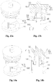
- the end cap assembly may also be as shown in Figure 13 .
- the end cap assembly in this solution includes a cap body 4a1 and a seat body 4b1, the second spring 32, the first retainer ring 52 and the spring seat 54.
- the second spring 32, the first retainer ring 52, the spring seat 54 are arranged together with the cap body 4a1.
- the second spring 32 and the spring seat 54 are limited to the accommodating chamber of the cap body by the first retainer ring 52 fitting with the groove 401.
- the seat body 4b1 includes a valve seat portion 44, a guide portion 46 and a first connection portion 43.
- the valve seat portion is larger than the guide portion, and a hole of the valve seat portion is larger than a hole of the guide portion.
- the guide portion is arranged close to the cap body relative to the valve seat portion, and the valve seat portion is arranged away from the cap body relative to the guide portion.
- the first connection portion 43 connects the guide portion and the valve seat portion.
- the cap body 4a1 is further provided with a communication hole 413 for communicating the accommodating chamber 401 with the outside thereof.
- the first outer wall portion of the thermal actuator no longer serves as the guide fitting portion, but a portion of the valve rod of the thermal actuator is fitted with the hole of the guide portion 46 to achieve the slidable guiding, such that the thermostatic valve has a reduced length while achieving a good guide performance of movement.
- the seat body may be in a clearance-fit with the cap body.
- the cap body and the seat body have an axial limiting structure and a radial limiting structure to avoid a radial movement of the seat body and an axial movement towards the cap body.
- the limitation of the movement of the seat body towards the cap body may be achieved by the first retainer ring 52 as shown in Figure 13a and Figure 13b .
- a step portion may be arranged on the cap body to achieve the axial movement of the seat body toward the cap body.
- the cap body may also be in a transition-fit or tight fit with the cap body.
- the seat body may be tightly fitted with the valve body to achieve a limitation of movement toward the interior of the chamber, that is, towards the first valve port, such that the seat body is relatively limited to the chamber 10 of the valve body.
- the guide portion is also arranged close to the cap body 4a1, and the guide portion and the second connection portion which are relatively away from the cap body are omitted.
- the cap body 4a1 and the seat body 4b1 may also be fitted and fixed through threads.
- the first spring and the thermal actuator may be assembled first, and then the seat body and the cap body are assembled with the valve body. Besides, the first spring and the thermal actuator may be assembled with the valve body, and then the seat body and cap body are assembled successively. Moreover, the first spring may be assembled first.
- the assembly in this solution is relatively simply, and others may refer to the above-described embodiments.
- the end cap assembly may also be as shown in Figure 14a and Figure 14b .
- the end cap assembly includes an end cap 4', the second spring 32, the spring seat 54 and the guide member 47.
- the end cap 4' includes a body portion 41, a valve seat portion 44 and a first connection portion 43.
- the guide member and the end cap may be fixed by, for example, welding, thread fastening, tight fitting, interference riveting or a combination of two or more of the fixing manners as listed, such that the spring seat is fixed by the guide member, and the retainer ring may not be used any more.
- a sealing member 53 may be arranged between the end cap assembly and the valve body, to increase the sealing performance between the end cap assembly and the valve body.
- the body portion 41, the valve seat portion 44 and the first connection portion 43 are arranged on the end cap 4, and the guide portion is arranged on the guide member, such that the second connection portion is not required.
- the body portion 41 and the valve seat portion 44 are connected by the first connection portion 43.
- the guide portion 46 is fitted with the valve rod of the thermal actuator for guiding, and the guide portion 46 may also be fitted with the first outer wall portion of the thermal actuator for guiding.
- the outer diameter of the hole for fitting and guiding is larger than an outer diameter of a portion of the thermal actuator for fitting and guiding by 0.05mm to 0.5mm.
- a gap between the hole of the guide member for fitting and guiding and the portion of the thermal actuator for fitting and guiding may be slightly smaller than a gap between the valve rod of the thermal actuator and a hole of the spring seat.
- the guide portion of the thermostatic valve has an annular structure.
- the guide portion may also have a combined structure of a plurality of column structures, and the thermal actuator does not disengage from the guide portion with the combined structure.
- the guide portion has a structure similar to a combination of two or more arc-shaped columns, each of which may be a part of the same annular structure.
- the interior of the guide portion may have an arc-shaped structure fitting with the structure of the thermal actuator. In this way, the guide of the thermal actuator can also be achieved.
- the length of the guide portion of the end cap assembly fitting with the guide fitting portion of the thermal actuator is greater than a stroke of the thermal actuator in the chamber, for example, by more than 1mm, such that the thermal actuator is always fitted with the guide portion while moving in the chamber.
- the guide fitting portion is the first outer wall portion or the valve rod of the thermal actuator.
- the guide fitting portion may also be a transition portion 27 between the first outer wall portion and the exposed valve rod.
- the first port may be selected as the inlet of the thermostatic valve.
- the flow modes of the fluid in two different operating conditions are respectively as shown in Figure 2 or Figure 3 , and the fluid in the thermostatic valve may also flow in directions indicated by the dotted arrows shown in Figure 2 and Figure 3 .
- a communication pipe may be provided outside the thermostatic valve, and the flow of fluid into the thermostatic valve from the third port can also achieve the control performance of the thermostatic valve.
- the guide portion is arranged at the end cap assembly, and is partially arranged at the end cap.
- some of the end cap assemblies may also include the cap body and the seat body, and the guide portion is arranged at the seat body, and the seat body may be assembled with the cap body as an integrated structure.
- the seat body and the cap body may also be arranged as separate structures, and form a relatively fixed structure after being assembled into the chamber of the valve body.
- the seat body may be fixed to the end cap or the cap body of the end cap assembly; or may also be fixed through the end cap or the cap body and the valve body.
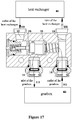
- the temperature control system shown in Figure 15 to Figure 17 is described as an example.
- Figure 15 to Figure 17 are schematic diagrams of a specific application manner of the temperature controller according to the present application in a temperature control system.
- the temperature control system includes a thermostatic valve, a heat exchanger 61 and a gearbox 62.
- the thermostatic valve has four ports. Two ports on one side are respectively in communication with an inlet and an outlet of a cooling fluid circuit of the heat exchanger. The other two ports on the same side are respectively in communication with an inlet and an outlet of the cooling fluid circuit of the gearbox.
- the first port 11 of the thermostatic valve is in communication with the cooling fluid inlet of the gearbox, and the fourth port 14 of the thermostatic valve is in communication with the cooling fluid outlet of the gearbox.
- the second port 12 of the thermostatic valve is in communication with the cooling fluid outlet of the heat exchanger
- the third port 13 of the thermostatic valve is in communication with the cooling fluid inlet of the heat exchanger.
- the first port and the fourth port are located on a side of the thermostatic valve relatively close to the gearbox
- the second port and the third port are located on the other side of the thermostatic valve relatively close to the cooling box.
- the fluid flows out from the first fluid port 141 as the fluid outlet of the gearbox and flows into the thermostatic valve from the fourth port 14 of the thermostatic valve. Then, the fluid flows into the first fluid port 131 of the heat exchanger from the third port 13 through the third chamber, the first fluid port 131 serves as the fluid inlet of the heat exchanger. Then, the fluid, after performing heat exchange in the heat exchanger, passes through the second fluid port 121 of the heat exchanger, the second fluid port 121 serves as the fluid outlet of the heat exchanger.
- the fluid flows into the thermostatic valve through the second port 12, and flows to the first port through the second valve port, then flows back to the gearbox 62 from the first port 11 through the second fluid port 111 of the gearbox.
- the second fluid port 111 serves as the fluid inlet of the gearbox.
- the fluid may perform heat exchange in the heat exchanger 61.
- the heat exchanger may be a cooler, or may be a double-flow heat exchanger.
- the heat exchanger may be a gas-liquid heat exchanging type heat exchanger or a liquid-liquid heat exchanging type heat exchanger.
- the heat sensitive material in the thermal actuator shrinks, and the body of the thermal actuator body moves toward the second valve port until the second valve element abuts against the second valve seat and blocks the second valve port.
- the fluid flows out from the first fluid port 141 of the gearbox and flows into the thermostatic valve from the fourth port 14, and passes through the third chamber and the second chamber 102 communicating with the third chamber.
- the fluid flows into the first chamber through the opened first valve port and flows out of the thermostatic valve from the first port 11 communicating with the first chamber, then the fluid flows back to the gearbox 62 through the second fluid port 111 serving as the inlet of the gearbox, without performing heat exchange in the heat exchanger, that is, the fluid is not cooled by the heat exchanger. In this way, the oil temperature is controlled within an appropriate range.
- the temperature control system When the temperature control system is abnormal, the temperature control system operates under an abnormal pressure relief condition.
- the fluid flowing out from the outlet of the gearbox has an increased pressure due to the abnormal circulation of the fluid. That is, the pressure in the space where the second chamber and the third chamber of the thermostatic valve are located is increased.
- the fluid does not flow smoothly or is blocked, the first valve port is closed, and also the first chamber has a relatively low pressure due to communication with the inlet of the gearbox, thus there is a pressure difference between two sides of the first valve port, that is, between the second chamber and the first chamber.
- the thermal actuator of the thermostatic valve moves toward the second valve port under the effect of the pressure difference, that is, the safety pressure relief occurs, such that the failure of the system is avoided, that is, the temperature control system may achieve pressure relief under an abnormal pressure condition. In this way, it is not necessary to separately provide a pressure relief device to achieve the pressure relief, and the structure of the thermostatic valve is relatively simple.
- the temperature control system may also be as shown in Figure 18 , which is a schematic diagram of another application manner of the temperature controller in the temperature control system.
- the temperature control system includes a thermostatic valve, the heat exchanger 61 and the gearbox 62.
- the thermostatic valve has four ports, in which the two ports on one side, that is the second port and the third port, are respectively in communication with an inlet and an outlet of a cooling fluid circuit of the heat exchanger.
- the other two ports on the same side, that is, the first port and the fourth port are respectively in communication with the inlet and the outlet of the cooling fluid circuit of the gearbox.
- the first port 11 of the thermostatic valve is in communication with the second fluid port of the gearbox.
- the second fluid port serves as the cooling fluid outlet of the gearbox.
- the fourth port 14 of the thermostatic valve is in communication with the first fluid port of the gearbox.
- the first fluid port serves as the cooling fluid inlet of the gearbox.
- the second port of the thermostatic valve is in communication with the second fluid port of the heat exchanger, and the second fluid port serves as the cooling fluid inlet of the heat exchanger.
- the third port 13 of the thermostatic valve is in communication with the first fluid port of the heat exchanger.
- the first fluid port of the heat exchanger at this time serves as the cooling fluid outlet of the heat exchanger
- the third port 13 of the thermostatic valve is in communication with the first fluid port of the gearbox
- the first fluid port of the heat exchanger is in communication with the first fluid port of the gearbox.
- the temperature control system may also be as shown in Figure 19 , and in this solution, the thermostatic valve has three ports.
- the first port of the thermostatic valve is in communication with the second fluid port 111 of the gearbox, and the second port of the thermostatic valve is in communication with the second fluid port 121 of the heat exchanger.
- the first fluid port 131 of the heat exchanger serves as the fluid outlet of the heat exchanger, and the second fluid port 121 of the heat exchanger serves as the fluid inlet of the heat exchanger.
- the second fluid port of the gearbox serves as a fluid outlet of the gearbox, and the first fluid port 141 of the gearbox serves as a fluid inlet of the gearbox.
- the third port of the thermostatic valve is in communication with the first fluid port of the gearbox.
- the first fluid port of the heat exchanger is in communication with the first fluid port of the gearbox.
- the communication manner includes that the third port of the thermostatic valve and the first fluid port of the heat exchanger are respectively in communication with the first fluid port of the gearbox, and the third port of the thermostatic valve is in communication with the first fluid port of the heat exchanger, and the two ports are together in communication with the first fluid port of the gearbox.
Landscapes
- Engineering & Computer Science (AREA)
- General Engineering & Computer Science (AREA)
- Mechanical Engineering (AREA)
- Chemical & Material Sciences (AREA)
- Combustion & Propulsion (AREA)
- Physics & Mathematics (AREA)
- Fluid Mechanics (AREA)
- General Physics & Mathematics (AREA)
- Automation & Control Theory (AREA)
- Temperature-Responsive Valves (AREA)
Claims (12)
- Soupape thermostatique, comprenant :un corps de soupape (1) dans lequel une chambre est fournie,un ensemble capuchon d'extrémité, etun actionneur thermique (2) et un premier ressort (31) montés dans la chambre :le corps de soupape (1) étant pourvu d'au moins trois orifices en communication avec l'extérieur, les trois orifices comprenant un premier orifice (11), un deuxième orifice (12) et un troisième orifice (13) ;l'actionneur thermique (2) comprenant une tige de soupape (24) et un corps (22),la chambre comprenant une première chambre (101) et une deuxième chambre (102), un diamètre de la deuxième chambre (102) étant inférieur à un diamètre de la première chambre (101), la deuxième chambre (102) étant à l'écart de l'ensemble capuchon d'extrémité par rapport à la première chambre (101) ;le premier orifice (11) étant en communication avec la première chambre (101), le troisième orifice (13) étant en communication avec la deuxième chambre (102) ;le premier ressort (31) étant situé partiellement ou entièrement dans la deuxième chambre (102) ;l'actionneur thermique (2) étant situé principalement ou entièrement dans la première chambre (101), la première chambre (101) étant plus grande que l'actionneur thermique (2) ;une extrémité de l'actionneur thermique (2) venant en butée contre ou venant indirectement en butée contre ou supportant une extrémité du premier ressort (31) proche de l'actionneur thermique (2), et une autre extrémité de l'actionneur thermique (2) où la tige de soupape (24) est située étant limitée à l'ensemble capuchon d'extrémité, caractérisée en ce quel'ensemble capuchon d'extrémité comprend un capuchon d'extrémité (4), et le capuchon d'extrémité (4) comprend une partie de siège de soupape (44), une partie de guidage (46) et une première partie de liaison (43), la première partie de liaison (43) relie la partie de guidage (46) et la partie de siège de soupape (44), et la première partie de liaison (43) est située entre la partie de guidage (46) et la partie de siège de soupape (44) ; l'actionneur thermique (2) comprend une partie d'ajustement de guidage ajustée à la partie de guidage (46), et la partie de guidage (46) est ajustée de manière coulissante avec la partie d'ajustement de guidage ; etla soupape thermostatique comprend un premier siège de soupape (15) et un deuxième siège de soupape (16) tous deux disposés de manière fixe, le premier siège de soupape (15) comprend un premier orifice de soupape (150) ; etle premier siège de soupape (15) étant situé à une position de la deuxième chambre (102) relativement proche de la première chambre (101), ou le premier siège de soupape (15) étant situé à une position de la première chambre (101) relativement proche de la deuxième chambre (102) ; etle deuxième siège de soupape (16) étant situé au niveau de la partie de siège de soupape (44).
- Soupape thermostatique selon la revendication 1, dans laquelle
dans une direction axiale du corps de soupape (1), le premier siège de soupape (15) est situé à une position entre le premier orifice (11) et le troisième orifice (13) du corps de soupape (1), le deuxième siège de soupape (16) est situé à une position entre le premier orifice (11) et le deuxième orifice (12) du corps de soupape (1) ;
l'actionneur thermique (2) comprend en outre un premier noyau de soupape (21) disposé par rapport au premier siège de soupape (15) et un deuxième noyau de soupape (231) disposé par rapport au deuxième siège de soupape (16), le premier noyau de soupape (21), le deuxième noyau de soupape (231) et le corps (22) de l'actionneur thermique (2) étant formés comme une structure intégrale ou étant disposés de manière fixe ; et
un diamètre intérieur de la partie de guidage (46) est supérieur à la partie d'ajustement de guidage de l'actionneur thermique (2), et le diamètre intérieur de la partie de guidage (46) est supérieur à un diamètre extérieur de la partie d'ajustement de guidage de l'actionneur thermique (2) de 0,05 mm à 0,5 mm, et une longueur de la partie de guidage (46) de l'ensemble capuchon d'extrémité ou une longueur de la partie d'ajustement de guidage de l'actionneur thermique (2) est supérieure à une course de l'actionneur thermique (2) mobile dans la chambre. - Soupape thermostatique selon la revendication 1 ou 2, dans laquelle l'ensemble capuchon d'extrémité comprend en outre une deuxième partie de liaison, chacune de la partie de guidage (46) et de la partie de siège de soupape (44) a sensiblement une structure annulaire, un trou intérieur de la partie de siège de soupape (44) est plus petit qu'un trou intérieur de la partie de guidage (46), un diamètre extérieur de la partie de siège de soupape (44) est plus grand qu'un diamètre extérieur de la partie de guidage (46) ;
la partie de siège de soupape (44) est située entre la première partie de liaison (43) et la deuxième partie de liaison (45), la partie de guidage (46) est située près du premier orifice de soupape (150) par rapport à la partie de siège de soupape (44) ; et
le corps (22) de l'actionneur thermique (2) comprend une partie de paroi extérieure qui est la partie d'ajustement de guidage, et un diamètre intérieur de la partie de guidage (46) est supérieur à un diamètre extérieur de la partie de paroi extérieure de l'actionneur thermique (2). - Soupape thermostatique selon la revendication 1 ou 2, dans laquelle l'ensemble capuchon d'extrémité comprend en outre un siège de ressort (54) et un deuxième ressort (32), le capuchon d'extrémité (4) est pourvu d'une chambre de logement (401), le deuxième ressort (32) et le siège de ressort (54) sont situés dans la chambre de logement (401), le siège de ressort (54) est limité à la chambre de logement (401) par une bague de retenue ou un autre dispositif de limitation disposé de manière fixe avec le capuchon d'extrémité (4), une extrémité du deuxième ressort (32) vient en butée contre la chambre de logement (401), et une autre extrémité du deuxième ressort (32) vient en butée contre le siège de ressort (54) ;
le siège de ressort (54) est manchonné sur une partie d'extrémité d'une tige de soupape (24) de l'actionneur thermique (2), et la tige de soupape (24) s'étend partiellement dans une chambre intérieure du siège de ressort (54). - Soupape thermostatique, comprenant :un corps de soupape (1) dans lequel une chambre est fournie,un ensemble capuchon d'extrémité, etun actionneur thermique (2) et un premier ressort (31) montés dans la chambre :le corps de soupape (1) étant pourvu d'au moins trois orifices en communication avec l'extérieur, les trois orifices comprenant un premier orifice (11), un deuxième orifice (12) et un troisième orifice (13) ;l'actionneur thermique (2) comprenant une tige de soupape (24) et un corps (22),la chambre comprenant une première chambre (101) et une deuxième chambre (102), un diamètre de la deuxième chambre (102) étant inférieur à un diamètre de la première chambre (101), la deuxième chambre (102) étant à l'écart de l'ensemble capuchon d'extrémité par rapport à la première chambre (101) ;le premier orifice (11) étant en communication avec la première chambre (101), le troisième orifice (13) étant en communication avec la deuxième chambre (102) ;le premier ressort (31) étant situé partiellement ou entièrement dans la deuxième chambre (102) ;l'actionneur thermique (2) étant situé principalement ou entièrement dans la première chambre (101), la première chambre (101) étant plus grande que l'actionneur thermique (2) ;une extrémité de l'actionneur thermique (2) venant en butée contre ou venant indirectement en butée contre ou supportant une extrémité du premier ressort (31) proche de l'actionneur thermique (2), et une autre extrémité de l'actionneur thermique (2) où la tige de soupape (24) est située étant limitée à l'ensemble capuchon d'extrémité ; etla soupape thermostatique étant en outre pourvue d'une partie de guidage (46) dans la chambre, l'actionneur thermique (2) comprenant une partie d'ajustement de guidage ajustée à la partie de guidage (46), et la partie de guidage (46) étant ajustée de manière coulissante avec la partie d'ajustement de guidage ; caractérisée en ce quel'ensemble capuchon d'extrémité comprend un capuchon d'extrémité (4'), un siège de ressort (54), un deuxième ressort (32) et un élément de guidage (47), le capuchon d'extrémité (4') est pourvu d'une chambre de logement (401), le deuxième ressort (32) et le siège de ressort (54) sont situés dans la chambre de logement (401), l'élément de guidage (47) est conçu de manière fixe avec le capuchon d'extrémité (4'), le siège de ressort (54) est limité à la chambre de logement (401) par l'élément de guidage (47), une extrémité du deuxième ressort (32) vient en butée contre la chambre de logement (401) et une autre extrémité du deuxième ressort (32) vient en butée contre le siège de ressort (54) ;le siège de ressort (54) est manchonné sur une partie d'extrémité d'une tige de soupape (24) de l'actionneur thermique (2), et la tige de soupape (24) s'étend partiellement dans une chambre intérieure du siège de ressort (54) ; etle bouchon d'extrémité (4') comprend une partie de siège de soupape (44), une première partie de liaison (43) et une partie de corps (41) pour s'ajuster à une extrémité ouverte de la chambre, la partie de siège de soupape (44) et la partie de corps (41) sont reliées par la première partie de liaison (43), et l'élément de guidage (47) est pourvu d'un trou de guidage pour fonctionner comme la partie de guidage (46).
- Soupape thermostatique selon l'une quelconque des revendications 1 à 2, dans laquelle l'ensemble capuchon d'extrémité comprend un deuxième ressort (32), un corps de capuchon (4a), un corps de siège (4b) et un siège de ressort (54), le corps de capuchon (4a) et le corps de siège (4b) sont relativement fixes et ajustés par des filets, le corps de capuchon (4a) est ajusté avec le corps de siège (4b) pour former une chambre de logement (401) pour accueillir le deuxième ressort (32) et le siège de ressort (54), le corps de siège (4b) est pourvu d'une partie étagée pour venir en butée contre le siège de ressort (54), le deuxième ressort (32) et le siège de ressort (54) sont situés dans la chambre de logement (401), une extrémité du deuxième ressort (32) vient en butée contre le corps de capuchon (4a), et une autre extrémité du deuxième ressort (32) vient en butée contre le siège de ressort (54) ;
le corps de siège (4b) comprend la partie de siège de soupape (44), la partie de guidage (46) et la première partie de liaison (43) ; et
le corps de siège (4b) est fait d'un matériau plastique par moulage par injection, et le corps de capuchon (4a) est fait d'un matériau métallique. - Soupape thermostatique selon l'une quelconque des revendications 1 à 2, dans laquelle l'ensemble capuchon d'extrémité comprend un deuxième ressort (32), un corps de capuchon (4a'), un corps de siège (4b') et un siège de ressort (54), le corps de capuchon (4a') comprend une chambre de logement (401) pour accueillir le deuxième ressort (32) et le siège de ressort (54), la chambre de logement (401) est pourvue d'une rainure pour accueillir une bague de retenue, la bague de retenue est partiellement située dans la rainure pour atteindre une limitation de position axiale, le siège de ressort (54) vient en butée contre la bague de retenue, le deuxième ressort (32) et le siège de ressort (54) sont situés dans la chambre de logement (401), une extrémité du deuxième ressort (32) vient en butée contre le corps de bouchon (4a'), et une autre extrémité du deuxième ressort (32) vient en butée contre le siège de ressort (54) ;
le corps de siège (4b') comprend la partie de siège de soupape (44), la partie de guidage (46) et la première partie de liaison (43) ;
le corps de siège (4b') est disposé de manière fixe avec le corps de capuchon (4a'), ou le corps de siège (4b') est ajusté de manière serrée avec le corps de capuchon (4a'), ou l'un ou les deux du corps de siège (4b') et du corps de capuchon (4a') sont pourvus d'une structure de limitation pour empêcher le corps de siège (4b') de se déplacer vers le corps de capuchon (4a'), et le corps de soupape (1) est pourvu d'une partie étagée pour limiter la position à une position de la chambre ajustée au corps de siège (4b') pour empêcher le corps de siège (4b') de se déplacer vers le premier orifice de soupape (150) dans la chambre. - Soupape thermostatique selon l'une quelconque des revendications 1 à 2, dans laquelle l'ensemble capuchon d'extrémité comprend un deuxième ressort (32), un corps de capuchon (4a'), un corps de siège (4b') et un siège de ressort (54), le corps de capuchon (4a') comprend une chambre de logement (401) pour accueillir le deuxième ressort (32) et le siège de ressort (54), la chambre de logement (401) est pourvue d'une rainure pour accueillir une bague de retenue, la bague de retenue est partiellement située dans la rainure pour atteindre une limitation de position axiale, le siège de ressort (54) vient en butée contre la bague de retenue, le deuxième ressort (32) et le siège de ressort (54) sont situés dans la chambre de logement (401), une extrémité du deuxième ressort (32) vient en butée contre le corps de bouchon (4a'), et une autre extrémité du deuxième ressort (32) vient en butée contre le siège de ressort (54) ;
le corps de siège (4b') comprend la partie de siège de soupape (44), la partie de guidage (46) et la première partie de liaison (43) ;
le corps de siège (4b') est disposé de manière fixe avec le corps de capuchon (4a'), ou le corps de siège (4b') est ajusté de manière serrée avec le corps de capuchon (4a'), ou l'un ou les deux du corps de siège (4b') et du corps de capuchon (4a') sont pourvus d'une structure de limitation pour empêcher le corps de siège (4b') de se déplacer vers le corps de capuchon (4a'), et le corps de soupape (1) est pourvu d'une partie étagée pour limiter la position à une position de la chambre ajustée au corps de siège (4b') pour empêcher le siège de se déplacer vers le premier orifice de soupape (150) dans la chambre ; et
la partie de guidage (46) est disposée près du corps de capuchon (4a') par rapport à la partie de siège de soupape (44), et la tige de soupape (24) de l'actionneur thermique (2) servent de partie d'ajustement de guidage ajustée à la partie de guidage (46). - Soupape thermostatique selon la revendication 8, dans laquelle le corps de soupape (1) comprend en outre un quatrième orifice (14) en communication avec l'extérieur, le quatrième orifice (14) et le troisième orifice (13) sont respectivement situés sur deux côtés opposés du corps de soupape (1), le quatrième orifice (14) et le troisième orifice (13) sont tous deux en communication avec une troisième chambre (103), le premier orifice (11) et le deuxième orifice (12) sont respectivement situés sur deux côtés opposés du corps de soupape (1), et dans les quatre orifices, le premier orifice (11) est situé du même côté du corps de soupape (1) que l'un du troisième orifice (13) et du quatrième orifice (14).
- Système de régulation de température, comprenant une soupape thermostatique, un échangeur de chaleur et une boîte de vitesses,
la soupape thermostatique étant la soupape thermostatique selon l'une quelconque des revendications 1 à 9 ;
l'échangeur de chaleur comprenant un premier orifice de fluide (131) et un deuxième orifice de fluide (121), et la boîte de vitesses comprenant un premier orifice de fluide (141) et un deuxième orifice de fluide (111) ;
le premier orifice (11) de la soupape thermostatique étant en communication avec le deuxième orifice de fluide (111) de la boîte de vitesses, et le deuxième orifice (12) de la soupape thermostatique étant en communication avec le deuxième orifice de fluide (121) de l'échangeur de chaleur, le premier orifice de fluide (131) de l'échangeur de chaleur servant de sortie de fluide de l'échangeur de chaleur, le deuxième orifice de fluide (121) de l'échangeur de chaleur servant d'entrée de fluide de l'échangeur de chaleur, et le deuxième orifice de fluide (111) de la boîte de vitesses servant de sortie de fluide de la boîte de vitesses, le premier orifice de fluide (141) de la boîte de vitesses servant d'entrée de fluide de la boîte de vitesses ; et
un troisième orifice (13) de la soupape thermostatique étant en communication avec le premier orifice de fluide (141) de la boîte de vitesses, et le premier orifice de fluide (131) de l'échangeur de chaleur étant en communication avec le premier orifice de fluide (141) de la boîte de vitesses. - Système de régulation de température, comprenant une soupape thermostatique, un échangeur de chaleur et une boîte de vitesses,
la soupape thermostatique étant la soupape thermostatique selon la revendication 9 ;
l'échangeur de chaleur comprenant un premier orifice de fluide (131) et un deuxième orifice de fluide (121), la boîte de vitesses comprenant un premier orifice de fluide (141) et un deuxième orifice de fluide (111) ; et
le premier orifice (11) de la soupape thermostatique étant en communication avec le deuxième orifice de fluide (111) de la boîte de vitesses, et le quatrième orifice (14) de la soupape thermostatique étant en communication avec le premier orifice de fluide (141) de la boîte de vitesses, le deuxième orifice (12) de la soupape thermostatique étant en communication avec le deuxième orifice de fluide (121) de l'échangeur de chaleur, et le troisième orifice (13) de la soupape thermostatique étant en communication avec le premier orifice de fluide (131) de l'échangeur de chaleur. - Système de régulation de température selon la revendication 11, dans lequel le premier orifice de fluide (131) de l'échangeur de chaleur sert d'entrée de fluide de l'échangeur de chaleur, et le deuxième orifice de fluide (121) de l'échangeur de chaleur sert de sortie de fluide de l'échangeur de chaleur, le premier orifice de fluide (141) de la boîte de vitesses sert de sortie de fluide de la boîte de vitesses, et le deuxième orifice de fluide (111) de la boîte de vitesses sert d'entrée de fluide de la boîte de vitesses ; et
un processus de fonctionnement du système de régulation de température comprend en outre une condition de décharge de pression anormale, dans laquelle une pression de la deuxième chambre (102) est supérieure à une pression de la première chambre (101) de la soupape thermostatique, une force générée par une différence entre la pression de la deuxième chambre (102) et la pression de la première chambre (101) amène l'actionneur thermique (2) à s'éloigner du premier orifice de soupape (150) pour ouvrir le premier orifice de soupape (150).
Applications Claiming Priority (3)
| Application Number | Priority Date | Filing Date | Title |
|---|---|---|---|
| CN201610257372.1A CN107304844B (zh) | 2016-04-21 | 2016-04-21 | 一种调温器及一种温控系统 |
| CN201610256981.5A CN107304834B (zh) | 2016-04-21 | 2016-04-21 | 一种温控系统 |
| PCT/CN2017/080043 WO2017181869A1 (fr) | 2016-04-21 | 2017-04-11 | Thermostat et système de régulation de température |
Publications (3)
| Publication Number | Publication Date |
|---|---|
| EP3447350A1 EP3447350A1 (fr) | 2019-02-27 |
| EP3447350A4 EP3447350A4 (fr) | 2019-12-18 |
| EP3447350B1 true EP3447350B1 (fr) | 2021-06-23 |
Family
ID=60115571
Family Applications (1)
| Application Number | Title | Priority Date | Filing Date |
|---|---|---|---|
| EP17785354.6A Active EP3447350B1 (fr) | 2016-04-21 | 2017-04-11 | Thermostat et système de régulation de température |
Country Status (4)
| Country | Link |
|---|---|
| US (1) | US11408327B2 (fr) |
| EP (1) | EP3447350B1 (fr) |
| KR (1) | KR102103337B1 (fr) |
| WO (1) | WO2017181869A1 (fr) |
Families Citing this family (11)
| Publication number | Priority date | Publication date | Assignee | Title |
|---|---|---|---|---|
| CN107314150B (zh) * | 2016-04-26 | 2019-09-17 | 浙江三花汽车零部件有限公司 | 调温阀 |
| WO2017206750A1 (fr) * | 2016-05-31 | 2017-12-07 | 浙江三花汽车零部件有限公司 | Soupape de régulation de température |
| CN211738083U (zh) * | 2019-11-20 | 2020-10-23 | 浙江三花制冷集团有限公司 | 一种电动阀 |
| CN112780799B (zh) * | 2019-11-08 | 2025-08-12 | 浙江三花汽车零部件有限公司 | 流体控制阀 |
| CN112032148B (zh) * | 2020-08-25 | 2021-12-28 | 南京鑫姆迪克液压技术有限公司 | 单向温控阀 |
| US20220137653A1 (en) * | 2020-10-29 | 2022-05-05 | Sonnax Transmission Company | Cooler bypass manifold, method for modifying cooler bypass manifold and kit for modifying cooler bypass manifold |
| JP2022181783A (ja) * | 2021-05-27 | 2022-12-08 | 株式会社山田製作所 | 複合バルブ装置 |
| US11591964B2 (en) * | 2021-06-17 | 2023-02-28 | Pratt & Whitney Canada Corp. | Oil cooling system for aircraft engine |
| CN113374889B (zh) * | 2021-06-29 | 2024-11-01 | 奥特凯姆(中国)汽车部件有限公司 | 泄压式气动控制阀 |
| US12129043B1 (en) * | 2023-08-28 | 2024-10-29 | Pratt & Whitney Canada Corp. | Aircraft heat exchanger bypass flow control with electric motor |
| CN119999519A (zh) * | 2025-03-12 | 2025-05-16 | 浙江宏业装备科技有限公司 | 一种用于蘑菇生产的处理液输送装置 |
Family Cites Families (14)
| Publication number | Priority date | Publication date | Assignee | Title |
|---|---|---|---|---|
| DE29619609U1 (de) | 1996-11-12 | 1997-01-16 | Behr Thermot-Tronik Gmbh & Co., 70806 Kornwestheim | Thermostatventil |
| CA2246462C (fr) | 1998-04-03 | 2004-05-11 | Yoshikazu Kuze | Systeme de refroidissement pour moteur d'automobile |
| US9557749B2 (en) * | 2001-07-30 | 2017-01-31 | Dana Canada Corporation | Valves for bypass circuits in heat exchangers |
| US6935569B2 (en) * | 2001-08-31 | 2005-08-30 | Huron, Inc. | Oil cooler bypass valve |
| FR2905312B1 (fr) | 2006-08-30 | 2008-10-31 | Vernet Sa | Vanne thermostatique destinee a etre interposee entre un reservoir de carburant et un moteur thermique, et circuit de circulation de carburant correspondant |
| US8141790B2 (en) * | 2008-11-21 | 2012-03-27 | Dana Canada Corporation | Thermal bypass valve with pressure relief capability |
| JP4892606B2 (ja) | 2009-05-29 | 2012-03-07 | トヨタ自動車株式会社 | サーモバルブ |
| US8696072B2 (en) | 2010-10-12 | 2014-04-15 | Honda Patents & Technologies North America, Llc | Shut-off valve for hydraulic system |
| CN103573958B (zh) * | 2012-08-07 | 2016-04-20 | 浙江三花汽车零部件有限公司 | 一种用于换热回路的调温器组件 |
| CN103867692B (zh) | 2012-12-15 | 2017-02-22 | 浙江三花汽车零部件有限公司 | 一种调温器 |
| WO2014023157A1 (fr) * | 2012-08-07 | 2014-02-13 | 浙江三花汽车零部件有限公司 | Thermorégulateur |
| CN103671854A (zh) | 2012-09-14 | 2014-03-26 | 浙江三花汽车零部件有限公司 | 一种变速箱油路调温器 |
| CN102954199B (zh) * | 2012-11-28 | 2016-03-30 | 安徽江淮汽车股份有限公司 | 一种自动变速箱油冷却系统 |
| CN204943001U (zh) * | 2015-02-04 | 2016-01-06 | 浙江三花汽车零部件有限公司 | 调温器 |
-
2017
- 2017-04-11 WO PCT/CN2017/080043 patent/WO2017181869A1/fr not_active Ceased
- 2017-04-11 US US16/087,837 patent/US11408327B2/en active Active
- 2017-04-11 EP EP17785354.6A patent/EP3447350B1/fr active Active
- 2017-04-11 KR KR1020187025777A patent/KR102103337B1/ko active Active
Non-Patent Citations (1)
| Title |
|---|
| None * |
Also Published As
| Publication number | Publication date |
|---|---|
| WO2017181869A1 (fr) | 2017-10-26 |
| EP3447350A1 (fr) | 2019-02-27 |
| KR102103337B1 (ko) | 2020-04-23 |
| US11408327B2 (en) | 2022-08-09 |
| US20190107037A1 (en) | 2019-04-11 |
| KR20180111937A (ko) | 2018-10-11 |
| EP3447350A4 (fr) | 2019-12-18 |
Similar Documents
| Publication | Publication Date | Title |
|---|---|---|
| EP3447350B1 (fr) | Thermostat et système de régulation de température | |
| EP2884134B1 (fr) | Thermorégulateur | |
| EP3467352B1 (fr) | Soupape de régulation de température | |
| CN107304844B (zh) | 一种调温器及一种温控系统 | |
| KR102110828B1 (ko) | 온도 조절 밸브 | |
| EP3059405B1 (fr) | Soupape thermostatique | |
| EP2884135A1 (fr) | Thermorégulateur et composant de thermorégulateur | |
| KR102380176B1 (ko) | 밸브 조립체, 열교환 조립체, 및 기어박스용 오일온도조절 시스템 | |
| CN107304834B (zh) | 一种温控系统 | |
| EP3543635B1 (fr) | Système de réglage de température d'huile de transmission, ensemble d'échange de chaleur et ensemble de vanne | |
| CN108087530B (zh) | 热交换组件 | |
| CN108087532B (zh) | 热交换组件 | |
| CN107448643B (zh) | 一种调温阀 | |
| CN107448642B (zh) | 一种调温阀 | |
| KR20200065050A (ko) | 열교환기 | |
| CN108087531B (zh) | 热交换组件 | |
| CN107448626B (zh) | 一种调温阀 |
Legal Events
| Date | Code | Title | Description |
|---|---|---|---|
| STAA | Information on the status of an ep patent application or granted ep patent |
Free format text: STATUS: THE INTERNATIONAL PUBLICATION HAS BEEN MADE |
|
| PUAI | Public reference made under article 153(3) epc to a published international application that has entered the european phase |
Free format text: ORIGINAL CODE: 0009012 |
|
| STAA | Information on the status of an ep patent application or granted ep patent |
Free format text: STATUS: REQUEST FOR EXAMINATION WAS MADE |
|
| 17P | Request for examination filed |
Effective date: 20180917 |
|
| AK | Designated contracting states |
Kind code of ref document: A1 Designated state(s): AL AT BE BG CH CY CZ DE DK EE ES FI FR GB GR HR HU IE IS IT LI LT LU LV MC MK MT NL NO PL PT RO RS SE SI SK SM TR |
|
| AX | Request for extension of the european patent |
Extension state: BA ME |
|
| DAV | Request for validation of the european patent (deleted) | ||
| DAX | Request for extension of the european patent (deleted) | ||
| A4 | Supplementary search report drawn up and despatched |
Effective date: 20191120 |
|
| RIC1 | Information provided on ipc code assigned before grant |
Ipc: F16K 31/64 20060101AFI20191114BHEP Ipc: F01P 7/16 20060101ALI20191114BHEP Ipc: F16H 57/04 20100101ALI20191114BHEP Ipc: F16K 31/00 20060101ALI20191114BHEP |
|
| STAA | Information on the status of an ep patent application or granted ep patent |
Free format text: STATUS: EXAMINATION IS IN PROGRESS |
|
| 17Q | First examination report despatched |
Effective date: 20200318 |
|
| GRAP | Despatch of communication of intention to grant a patent |
Free format text: ORIGINAL CODE: EPIDOSNIGR1 |
|
| STAA | Information on the status of an ep patent application or granted ep patent |
Free format text: STATUS: GRANT OF PATENT IS INTENDED |
|
| INTG | Intention to grant announced |
Effective date: 20210114 |
|
| GRAS | Grant fee paid |
Free format text: ORIGINAL CODE: EPIDOSNIGR3 |
|
| GRAA | (expected) grant |
Free format text: ORIGINAL CODE: 0009210 |
|
| STAA | Information on the status of an ep patent application or granted ep patent |
Free format text: STATUS: THE PATENT HAS BEEN GRANTED |
|
| AK | Designated contracting states |
Kind code of ref document: B1 Designated state(s): AL AT BE BG CH CY CZ DE DK EE ES FI FR GB GR HR HU IE IS IT LI LT LU LV MC MK MT NL NO PL PT RO RS SE SI SK SM TR |
|
| REG | Reference to a national code |
Ref country code: GB Ref legal event code: FG4D |
|
| REG | Reference to a national code |
Ref country code: CH Ref legal event code: EP |
|
| REG | Reference to a national code |
Ref country code: DE Ref legal event code: R096 Ref document number: 602017040870 Country of ref document: DE Ref country code: AT Ref legal event code: REF Ref document number: 1404590 Country of ref document: AT Kind code of ref document: T Effective date: 20210715 |
|
| REG | Reference to a national code |
Ref country code: IE Ref legal event code: FG4D |
|
| REG | Reference to a national code |
Ref country code: LT Ref legal event code: MG9D |
|
| PG25 | Lapsed in a contracting state [announced via postgrant information from national office to epo] |
Ref country code: BG Free format text: LAPSE BECAUSE OF FAILURE TO SUBMIT A TRANSLATION OF THE DESCRIPTION OR TO PAY THE FEE WITHIN THE PRESCRIBED TIME-LIMIT Effective date: 20210923 Ref country code: HR Free format text: LAPSE BECAUSE OF FAILURE TO SUBMIT A TRANSLATION OF THE DESCRIPTION OR TO PAY THE FEE WITHIN THE PRESCRIBED TIME-LIMIT Effective date: 20210623 Ref country code: FI Free format text: LAPSE BECAUSE OF FAILURE TO SUBMIT A TRANSLATION OF THE DESCRIPTION OR TO PAY THE FEE WITHIN THE PRESCRIBED TIME-LIMIT Effective date: 20210623 Ref country code: LT Free format text: LAPSE BECAUSE OF FAILURE TO SUBMIT A TRANSLATION OF THE DESCRIPTION OR TO PAY THE FEE WITHIN THE PRESCRIBED TIME-LIMIT Effective date: 20210623 |
|
| REG | Reference to a national code |
Ref country code: AT Ref legal event code: MK05 Ref document number: 1404590 Country of ref document: AT Kind code of ref document: T Effective date: 20210623 |
|
| PG25 | Lapsed in a contracting state [announced via postgrant information from national office to epo] |
Ref country code: GR Free format text: LAPSE BECAUSE OF FAILURE TO SUBMIT A TRANSLATION OF THE DESCRIPTION OR TO PAY THE FEE WITHIN THE PRESCRIBED TIME-LIMIT Effective date: 20210924 Ref country code: RS Free format text: LAPSE BECAUSE OF FAILURE TO SUBMIT A TRANSLATION OF THE DESCRIPTION OR TO PAY THE FEE WITHIN THE PRESCRIBED TIME-LIMIT Effective date: 20210623 Ref country code: SE Free format text: LAPSE BECAUSE OF FAILURE TO SUBMIT A TRANSLATION OF THE DESCRIPTION OR TO PAY THE FEE WITHIN THE PRESCRIBED TIME-LIMIT Effective date: 20210623 Ref country code: NO Free format text: LAPSE BECAUSE OF FAILURE TO SUBMIT A TRANSLATION OF THE DESCRIPTION OR TO PAY THE FEE WITHIN THE PRESCRIBED TIME-LIMIT Effective date: 20210923 Ref country code: LV Free format text: LAPSE BECAUSE OF FAILURE TO SUBMIT A TRANSLATION OF THE DESCRIPTION OR TO PAY THE FEE WITHIN THE PRESCRIBED TIME-LIMIT Effective date: 20210623 |
|
| REG | Reference to a national code |
Ref country code: NL Ref legal event code: MP Effective date: 20210623 |
|
| PG25 | Lapsed in a contracting state [announced via postgrant information from national office to epo] |
Ref country code: SK Free format text: LAPSE BECAUSE OF FAILURE TO SUBMIT A TRANSLATION OF THE DESCRIPTION OR TO PAY THE FEE WITHIN THE PRESCRIBED TIME-LIMIT Effective date: 20210623 Ref country code: SM Free format text: LAPSE BECAUSE OF FAILURE TO SUBMIT A TRANSLATION OF THE DESCRIPTION OR TO PAY THE FEE WITHIN THE PRESCRIBED TIME-LIMIT Effective date: 20210623 Ref country code: NL Free format text: LAPSE BECAUSE OF FAILURE TO SUBMIT A TRANSLATION OF THE DESCRIPTION OR TO PAY THE FEE WITHIN THE PRESCRIBED TIME-LIMIT Effective date: 20210623 Ref country code: PT Free format text: LAPSE BECAUSE OF FAILURE TO SUBMIT A TRANSLATION OF THE DESCRIPTION OR TO PAY THE FEE WITHIN THE PRESCRIBED TIME-LIMIT Effective date: 20211025 Ref country code: RO Free format text: LAPSE BECAUSE OF FAILURE TO SUBMIT A TRANSLATION OF THE DESCRIPTION OR TO PAY THE FEE WITHIN THE PRESCRIBED TIME-LIMIT Effective date: 20210623 Ref country code: ES Free format text: LAPSE BECAUSE OF FAILURE TO SUBMIT A TRANSLATION OF THE DESCRIPTION OR TO PAY THE FEE WITHIN THE PRESCRIBED TIME-LIMIT Effective date: 20210623 Ref country code: AT Free format text: LAPSE BECAUSE OF FAILURE TO SUBMIT A TRANSLATION OF THE DESCRIPTION OR TO PAY THE FEE WITHIN THE PRESCRIBED TIME-LIMIT Effective date: 20210623 Ref country code: CZ Free format text: LAPSE BECAUSE OF FAILURE TO SUBMIT A TRANSLATION OF THE DESCRIPTION OR TO PAY THE FEE WITHIN THE PRESCRIBED TIME-LIMIT Effective date: 20210623 Ref country code: EE Free format text: LAPSE BECAUSE OF FAILURE TO SUBMIT A TRANSLATION OF THE DESCRIPTION OR TO PAY THE FEE WITHIN THE PRESCRIBED TIME-LIMIT Effective date: 20210623 |
|
| PG25 | Lapsed in a contracting state [announced via postgrant information from national office to epo] |
Ref country code: PL Free format text: LAPSE BECAUSE OF FAILURE TO SUBMIT A TRANSLATION OF THE DESCRIPTION OR TO PAY THE FEE WITHIN THE PRESCRIBED TIME-LIMIT Effective date: 20210623 |
|
| REG | Reference to a national code |
Ref country code: DE Ref legal event code: R097 Ref document number: 602017040870 Country of ref document: DE |
|
| PG25 | Lapsed in a contracting state [announced via postgrant information from national office to epo] |
Ref country code: DK Free format text: LAPSE BECAUSE OF FAILURE TO SUBMIT A TRANSLATION OF THE DESCRIPTION OR TO PAY THE FEE WITHIN THE PRESCRIBED TIME-LIMIT Effective date: 20210623 |
|
| PLBE | No opposition filed within time limit |
Free format text: ORIGINAL CODE: 0009261 |
|
| STAA | Information on the status of an ep patent application or granted ep patent |
Free format text: STATUS: NO OPPOSITION FILED WITHIN TIME LIMIT |
|
| 26N | No opposition filed |
Effective date: 20220324 |
|
| PG25 | Lapsed in a contracting state [announced via postgrant information from national office to epo] |
Ref country code: AL Free format text: LAPSE BECAUSE OF FAILURE TO SUBMIT A TRANSLATION OF THE DESCRIPTION OR TO PAY THE FEE WITHIN THE PRESCRIBED TIME-LIMIT Effective date: 20210623 |
|
| PG25 | Lapsed in a contracting state [announced via postgrant information from national office to epo] |
Ref country code: IT Free format text: LAPSE BECAUSE OF FAILURE TO SUBMIT A TRANSLATION OF THE DESCRIPTION OR TO PAY THE FEE WITHIN THE PRESCRIBED TIME-LIMIT Effective date: 20210623 |
|
| REG | Reference to a national code |
Ref country code: CH Ref legal event code: PL |
|
| GBPC | Gb: european patent ceased through non-payment of renewal fee |
Effective date: 20220411 |
|
| REG | Reference to a national code |
Ref country code: BE Ref legal event code: MM Effective date: 20220430 |
|
| PG25 | Lapsed in a contracting state [announced via postgrant information from national office to epo] |
Ref country code: MC Free format text: LAPSE BECAUSE OF FAILURE TO SUBMIT A TRANSLATION OF THE DESCRIPTION OR TO PAY THE FEE WITHIN THE PRESCRIBED TIME-LIMIT Effective date: 20210623 Ref country code: LU Free format text: LAPSE BECAUSE OF NON-PAYMENT OF DUE FEES Effective date: 20220411 Ref country code: LI Free format text: LAPSE BECAUSE OF NON-PAYMENT OF DUE FEES Effective date: 20220430 Ref country code: GB Free format text: LAPSE BECAUSE OF NON-PAYMENT OF DUE FEES Effective date: 20220411 Ref country code: FR Free format text: LAPSE BECAUSE OF NON-PAYMENT OF DUE FEES Effective date: 20220430 Ref country code: CH Free format text: LAPSE BECAUSE OF NON-PAYMENT OF DUE FEES Effective date: 20220430 |
|
| PG25 | Lapsed in a contracting state [announced via postgrant information from national office to epo] |
Ref country code: BE Free format text: LAPSE BECAUSE OF NON-PAYMENT OF DUE FEES Effective date: 20220430 |
|
| PG25 | Lapsed in a contracting state [announced via postgrant information from national office to epo] |
Ref country code: IE Free format text: LAPSE BECAUSE OF NON-PAYMENT OF DUE FEES Effective date: 20220411 |
|
| P01 | Opt-out of the competence of the unified patent court (upc) registered |
Effective date: 20230526 |
|
| PG25 | Lapsed in a contracting state [announced via postgrant information from national office to epo] |
Ref country code: HU Free format text: LAPSE BECAUSE OF FAILURE TO SUBMIT A TRANSLATION OF THE DESCRIPTION OR TO PAY THE FEE WITHIN THE PRESCRIBED TIME-LIMIT; INVALID AB INITIO Effective date: 20170411 |
|
| PG25 | Lapsed in a contracting state [announced via postgrant information from national office to epo] |
Ref country code: MK Free format text: LAPSE BECAUSE OF FAILURE TO SUBMIT A TRANSLATION OF THE DESCRIPTION OR TO PAY THE FEE WITHIN THE PRESCRIBED TIME-LIMIT Effective date: 20210623 Ref country code: CY Free format text: LAPSE BECAUSE OF FAILURE TO SUBMIT A TRANSLATION OF THE DESCRIPTION OR TO PAY THE FEE WITHIN THE PRESCRIBED TIME-LIMIT Effective date: 20210623 |
|
| PG25 | Lapsed in a contracting state [announced via postgrant information from national office to epo] |
Ref country code: MT Free format text: LAPSE BECAUSE OF FAILURE TO SUBMIT A TRANSLATION OF THE DESCRIPTION OR TO PAY THE FEE WITHIN THE PRESCRIBED TIME-LIMIT Effective date: 20210623 |
|
| PGFP | Annual fee paid to national office [announced via postgrant information from national office to epo] |
Ref country code: DE Payment date: 20250411 Year of fee payment: 9 |
|
| PG25 | Lapsed in a contracting state [announced via postgrant information from national office to epo] |
Ref country code: TR Free format text: LAPSE BECAUSE OF FAILURE TO SUBMIT A TRANSLATION OF THE DESCRIPTION OR TO PAY THE FEE WITHIN THE PRESCRIBED TIME-LIMIT Effective date: 20210623 |