EP3447399A2 - Procédé de rétrofittage d'un système d'extraction de fumée à un bâtiment et bâtiment avec un système d'extraction de fumée - Google Patents
Procédé de rétrofittage d'un système d'extraction de fumée à un bâtiment et bâtiment avec un système d'extraction de fumée Download PDFInfo
- Publication number
- EP3447399A2 EP3447399A2 EP18187811.7A EP18187811A EP3447399A2 EP 3447399 A2 EP3447399 A2 EP 3447399A2 EP 18187811 A EP18187811 A EP 18187811A EP 3447399 A2 EP3447399 A2 EP 3447399A2
- Authority
- EP
- European Patent Office
- Prior art keywords
- smoke
- building
- lift shaft
- lift
- ventilation device
- Prior art date
- Legal status (The legal status is an assumption and is not a legal conclusion. Google has not performed a legal analysis and makes no representation as to the accuracy of the status listed.)
- Withdrawn
Links
Images


Classifications
-
- F—MECHANICAL ENGINEERING; LIGHTING; HEATING; WEAPONS; BLASTING
- F24—HEATING; RANGES; VENTILATING
- F24F—AIR-CONDITIONING; AIR-HUMIDIFICATION; VENTILATION; USE OF AIR CURRENTS FOR SCREENING
- F24F7/00—Ventilation
-
- E—FIXED CONSTRUCTIONS
- E04—BUILDING
- E04F—FINISHING WORK ON BUILDINGS, e.g. STAIRS, FLOORS
- E04F17/00—Vertical ducts; Channels, e.g. for drainage
- E04F17/005—Lift shafts
-
- E—FIXED CONSTRUCTIONS
- E04—BUILDING
- E04F—FINISHING WORK ON BUILDINGS, e.g. STAIRS, FLOORS
- E04F17/00—Vertical ducts; Channels, e.g. for drainage
- E04F17/02—Vertical ducts; Channels, e.g. for drainage for carrying away waste gases, e.g. flue gases; Building elements specially designed therefor, e.g. shaped bricks or sets thereof
-
- E—FIXED CONSTRUCTIONS
- E04—BUILDING
- E04F—FINISHING WORK ON BUILDINGS, e.g. STAIRS, FLOORS
- E04F17/00—Vertical ducts; Channels, e.g. for drainage
- E04F17/04—Air-ducts or air channels
-
- F—MECHANICAL ENGINEERING; LIGHTING; HEATING; WEAPONS; BLASTING
- F24—HEATING; RANGES; VENTILATING
- F24F—AIR-CONDITIONING; AIR-HUMIDIFICATION; VENTILATION; USE OF AIR CURRENTS FOR SCREENING
- F24F11/00—Control or safety arrangements
- F24F11/30—Control or safety arrangements for purposes related to the operation of the system, e.g. for safety or monitoring
- F24F11/32—Responding to malfunctions or emergencies
- F24F11/33—Responding to malfunctions or emergencies to fire, excessive heat or smoke
- F24F11/34—Responding to malfunctions or emergencies to fire, excessive heat or smoke by opening air passages
-
- F—MECHANICAL ENGINEERING; LIGHTING; HEATING; WEAPONS; BLASTING
- F24—HEATING; RANGES; VENTILATING
- F24F—AIR-CONDITIONING; AIR-HUMIDIFICATION; VENTILATION; USE OF AIR CURRENTS FOR SCREENING
- F24F7/00—Ventilation
- F24F7/007—Ventilation with forced flow
-
- F—MECHANICAL ENGINEERING; LIGHTING; HEATING; WEAPONS; BLASTING
- F24—HEATING; RANGES; VENTILATING
- F24F—AIR-CONDITIONING; AIR-HUMIDIFICATION; VENTILATION; USE OF AIR CURRENTS FOR SCREENING
- F24F7/00—Ventilation
- F24F7/02—Roof ventilation
- F24F7/025—Roof ventilation with forced air circulation by means of a built-in ventilator
-
- F—MECHANICAL ENGINEERING; LIGHTING; HEATING; WEAPONS; BLASTING
- F24—HEATING; RANGES; VENTILATING
- F24F—AIR-CONDITIONING; AIR-HUMIDIFICATION; VENTILATION; USE OF AIR CURRENTS FOR SCREENING
- F24F7/00—Ventilation
- F24F7/04—Ventilation with ducting systems, e.g. by double walls; with natural circulation
- F24F7/06—Ventilation with ducting systems, e.g. by double walls; with natural circulation with forced air circulation, e.g. by fan positioning of a ventilator in or against a conduit
- F24F7/065—Ventilation with ducting systems, e.g. by double walls; with natural circulation with forced air circulation, e.g. by fan positioning of a ventilator in or against a conduit fan combined with single duct; mounting arrangements of a fan in a duct
-
- F—MECHANICAL ENGINEERING; LIGHTING; HEATING; WEAPONS; BLASTING
- F24—HEATING; RANGES; VENTILATING
- F24F—AIR-CONDITIONING; AIR-HUMIDIFICATION; VENTILATION; USE OF AIR CURRENTS FOR SCREENING
- F24F7/00—Ventilation
- F24F2007/001—Ventilation with exhausting air ducts
-
- F—MECHANICAL ENGINEERING; LIGHTING; HEATING; WEAPONS; BLASTING
- F24—HEATING; RANGES; VENTILATING
- F24F—AIR-CONDITIONING; AIR-HUMIDIFICATION; VENTILATION; USE OF AIR CURRENTS FOR SCREENING
- F24F2221/00—Details or features not otherwise provided for
- F24F2221/50—HVAC for high buildings, e.g. thermal or pressure differences
Definitions
- a method of retrofitting a smoke extractor system to a building having a plurality of storeys which are interconnected by a lift shaft comprising the steps of: installing a mechanical ventilation device to the lift shaft, the mechanical ventilation device having an inlet at or adjacent to the lift shaft and an outlet external to the building; and providing a smoke access path on each storey which couples each storey to the lift shaft and providing a smoke detector on each of the plurality of storeys; installing a controller for activating the mechanical ventilation device and opening and/or closing at least one of the smoke access paths; providing a first air access path between the stairwell and the exterior of the building comprising an automatically opening vent, openable by the controller; providing a second air access path between the stairwell and the lift shaft; the mechanical ventilation device, lift shaft and smoke access path defining a smoke extraction system such that in the event of smoke being detected by a said smoke detector on at least one of the plurality of storeys, there is a smoke escape
- This method allows for a smoke extractor system to be retrofitted to a building where a majority of the communal areas of the building are not adjacent to the exterior of the building.
- lift shafts are typically formed as an axially extending conduit through the building intersecting each storey and being adjacent to the exterior of the building at an upper portion of the lift shaft, they represent a suitable pathway for extracting smoke from a building.
- the smoke pathway allows for smoke to be ventilated from the building and therefore prevent, limit or reduce the risk of smoke inhalation by escaping occupants of the building.
- each smoke access path may be open or openable.
- the smoke access path may have a damper valve.
- each smoke access path is only open in the event of smoke being present on the associated storey. Providing for each smoke access path to be open or openable allows for smoke to move from the communal access area of each storey where it may be present to the lift shaft, thus reducing the risk of smoke inhalation to those in the communal access corridor.
- the smoke access path having a damper valve may allow for the smoke access path to be set interchangeably to either to the open condition, and so provide the benefits as previously described, or to the closed condition and thus prevent or limit smoke which may be present in the lift shaft from entering the storey where the smoke is not present. In this way smoke can be prevented or limited from spreading or infiltrating to other storeys and so occupants of the building present on those storeys can be at a lower risk of smoke inhalation.
- the controller allows for the remote and/or automatic operation and/or activation of the smoke extractor system.
- the smoke detector allows for the automatic detection of smoke and thus permit the automatic operation and/or activation of the smoke extractor system.
- the method may further comprise the step of an associated lift car of the lift shaft being driven at or adjacent to a ground storey of the building in the event of smoke being detected.
- the positioning of the lift car at or adjacent to the ground storey of the building results in a majority of the lift shaft being unobstructed and thus is a more effective path for the movement of smoke.
- the method may further comprise the step of providing sealant between the lift shaft and the plurality of storeys.
- the provision of sealant reduces or restricts the number of smoke leakage paths that may exist between the lift shaft and the plurality of storeys. This may prevent or limit smoke present in the lift shaft from accessing the or each storey which does not have smoke present.
- the method may further comprise the step of installing a lift-shaft-modification apparatus to the lift shaft, in order that the lift shaft can act as a pressurised smoke shaft.
- the lift-shaft-modification apparatus may comprise any or all of: mechanical lifting equipment; lift car; guide rails; wiring; lift controller; pulleys; cables; tracks; and counterweights.
- the lift-shaft-modification apparatus may comprise at least one restraining device for restraining movable components within the lift shaft upon activation of the smoke extraction system.
- lift-shaft-modification apparatus may advantageously allow older-style lift shafts to be retrofitted with a smoke extraction system.
- the lift shaft needs to be able to act as a pressurized smoke shaft for the building, and the existing lift cab and lifting mechanisms may not be suitable for this purpose.
- the lift-shaft-modification apparatus can serve to prevent these leakages, and also improve the smoke extraction efficiency of the retrofitted lift shaft.
- each vent may have a damper valve.
- the retrofittable apparatus may further comprise at least one smoke detector.
- the retrofittable apparatus may preferably further comprise a lift-shaft-modification apparatus to the lift shaft, in order that the lift shaft can act as a pressurised smoke shaft.
- the lift-shaft-modification apparatus may comprise any or all of: mechanical lifting equipment; lift car; guide rails; wiring; lift controller; pulleys; cables; tracks; and counterweights.
- the lift-shaft-modification apparatus may comprise at least one restraining device for restraining movable components within the lift shaft upon activation of the smoke extraction system.
- the lift-shaft-modification apparatus beneficially serves to improve the smoke extraction efficiency of the lift shaft, if applied correctly to the lift shaft.
- a building having a retrofittable apparatus in accordance with the second aspect of the invention to form a smoke extraction system comprising: a plurality of storeys; a lift shaft which interconnects the plurality of storeys; the inlet of the mechanical ventilation device being at or adjacent to the lift shaft and the outlet being external to the building; and the at least one vent being positioned between the lift shaft and each storey.
- the building may further comprise a stairwell.
- the building may further comprise a first air access path positioned between the exterior of the building and the stairwell.
- the building may further comprise a second air access path positioned between the stairwell and the lift shaft.
- the building may further comprise a smoke detector positioned on each of the plurality of storeys and operatively connected to the controller.
- a building having a retrofitted smoke extraction system comprising: a lift shaft; a plurality of storeys which are interconnected by the lift shaft; a smoke detector on each of the plurality of storeys; a controller for activating the mechanical ventilation device and opening and/or closing at least one of the smoke access paths; a first air access path between the stairwell and the exterior of the building comprising an automatically opening vent, openable by the controller; a second air access path between the stairwell and the lift shaft; a mechanical ventilation device on the lift shaft, the mechanical ventilation device having an inlet at or adjacent to the lift shaft and an outlet external to the building; a smoke access path on each storey which couples each storey to the lift shaft; and the mechanical ventilation device, lift shaft and smoke access path defining a smoke extraction system such that in the event of smoke being detected by a said smoke detector on at least one of the plurality of storeys, there is a smoke escape pathway from the or each storey through the associated
- a method of retrofitting a smoke extractor system to a building having a plurality of storeys which are interconnected by a lift shaft comprising the steps of: installing a mechanical ventilation device to the lift shaft, the mechanical ventilation device having an inlet at or adjacent to the lift shaft and an outlet external to the building; and providing a smoke access path on each storey which couples each storey to the lift shaft; the mechanical ventilation device, lift shaft and smoke access path defining a smoke extraction system such that in the event of smoke present on at least one of the plurality of storeys, there is a smoke escape pathway from the or each storey through the associated smoke access path, via the lift shaft and the mechanical ventilation device to an exterior of the building, the mechanical ventilation device providing an airflow through the smoke extraction system.
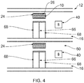
- FIG. 1 to 4 there is shown a retrofittable apparatus 10 installed on a building 14 to form a smoke extractor system 12.
- the building 14 is a high-rise building and thereby has a plurality of storeys, floors, levels or tiers 16.
- Smoke is herein defined as a suspension of particles, which may be carbon based, in air and/or a variety of gases which may include, but are not limited to, carbon dioxide, carbon monoxide, nitrogen oxides and sulphur oxides which are the result of combustion.
- gases may include, but are not limited to, carbon dioxide, carbon monoxide, nitrogen oxides and sulphur oxides which are the result of combustion.
- the present invention could thereby also be considered for the use of toxic gas extraction.
- the retrofittable apparatus 10 comprises at least one mechanical ventilation device 18 having an inlet 20 and an outlet 22.
- the mechanical ventilation device 18 may here be or have an extractor fan however may alternatively be or have an air pump or any other means for providing ventilation.
- two mechanical ventilation devices 18 are shown in Figure 1 any other number of mechanical ventilation devices may be provided. It is preferred that there are at least two, with a first mechanical ventilation device acting as a duty unit, with the or each further mechanical ventilation device acting as stand-by units in the event of failure of the duty unit.
- the retrofittable apparatus 10 further comprises a plurality of vents 24 which may have or take the form of conduits.
- Each conduit may be considered to be an elongate tube or tubing, having a rectangular or circular lateral cross-section and in use is for providing a path through a wall of a building, such as between a lift shaft and a storey.
- each vent 24 may preferably have an open and a closed condition and may therefore be or have a damper valve, having at least one blade 26 pivotably received across a lateral extent of the conduit.
- the or each blade 26 may preferably be or be substantially in the shape of a strip and therefore may be or be substantially planar.
- the or each blade 26 thereby has two planar faces separated by four edge portions and may be pivotable between a closed and an open position.
- the or each blade 26 When in the closed position the or each blade 26 may be orientated such that the planar faces are or are substantially aligned with the path of the conduit and thus occlude or substantially occlude the conduit. In the event of more than one blade 26 this may be achieved by a portion of each of the blades 26 being aligned or overlapping with each other. This may preferably create an air tight seal.
- the or each blade 26 When in the open condition the or each blade 26 may preferably be orientated such that an edge portion of the blade 26 is aligned with the path of the vent 24, thus creating a smoke escape path through the vent 24.
- vent 24 is described as being or having a damper valve, it is appreciated that the closable vent 24 may in fact have any kind of valve capable of restricting the flow of smoke through the conduit. Additionally, although the vent 24 is described as having an open and closed condition it is appreciated that the vent 24 may in fact not have a closed condition and may have a permanent path through the conduit for example, being formed as or having a ventilation grille.
- the retrofittable apparatus 10 may comprise at least one further vent, in use for providing a second air access path between a stairwell and a lift shaft.
- the further vent may be openable and/or closable and thus may be or have a damper valve having an electric motor to facilitate opening/closing.
- the further vent may not be openable and/or closable and therefore may only be a conduit.
- the retrofittable apparatus 10 may preferably also include at least one smoke detector 38 which may be operatively connected to the or each controller 36. There may preferably be a smoke detector 38 for each of the openable vents 24. Each smoke detector 38 may preferably be operatively connected to the or each controller 36, or alternatively, directly connected to the associated openable vent 24.
- At least one smoke seal or intumescent strip may also be included within the retrofittable apparatus 10.
- a manual override switch 40 for specific storeys may be included in the retrofittable apparatus which, when operated, may either activate or deactivate the smoke extractor system 12.
- the lift shaft 54 may additionally comprise a machine room, cavity or space positioned above the lift overrun for the storing and/or positioning of components to operate a lift car.
- a barrier may be between the machine room and the remainder of the lift shaft 54. This barrier may here take the form of a concrete slab or wall.
- a lift car may be received within the lift shaft 54 and may be movable along the longitudinal or vertical extent of the lift shaft 54.
- mechanical ventilation devices 18 may be considered which have an inlet 20 at or adjacent to any of the storeys 16 not adjacent to the exterior of the building 14 and an outlet 22 at the exterior of the building 14 adjacent to a longitudinal extent of the building 14 and in this way may have an extended elongate conduit through a lateral extent of the building 14.
- a smoke access path 24 is shown to be fitted to each of the storeys 16 above the ground storey 42, it is appreciated that a smoke access path 24 may in fact not be fitted to each of the storeys 16 and thus may only be fitted to a selection of stories. Additionally, it is appreciated a smoke access path 24 may be fitted to the ground storey 42 and/or the basement storey 48.
- the combination of the mechanical ventilation device 18, the lift shaft 54 and the smoke access path 24 between each storey 16 and the lift shaft 54 may in use thereby define a smoke escape pathway as well as the smoke extractor system 12.
- the mechanical ventilation device 18 in use causes a flow of air and/or smoke through the smoke escape pathway, from a communal access corridor or other location on the storey 16 where fire may be present to the exterior of the building.
- a second air access path may be provided between the stairwell 70 and the lift shaft 54.
- This second air access path may be defined as at least one aperture between the wall separating the stairwell 70 and the lift shaft 54.
- the further vent which may comprise a conduit and/or a damper valve and thus be openable and/or closable, may be installed.
- the second air access pathway may be positioned at, adjacent to or proximal to the ground storey 42 of the building 14; however, the second air access path may alternatively be positioned anywhere between the lift shaft 54 and the stairwell 70.
- the second air access path may be the result of air leakage paths between the stairwell 70 and the lift shaft 54 and may not be purposefully installed during the retrofitting process.
- the or each controller 36 may be installed to the building 14.
- a single controller 36 which is preferably operatively connected to the mechanical ventilation device 18, the electric motor of each vent 24, including the further vent of the second air access path if present, the automatically opening vent 28 and the lift car.
- At least one smoke detector 38 is preferably installed on each of the storeys 16 of the building 14. Each smoke detector 38 may be connected to the or each controller 36 in such a way so as to send a signal from each smoke detector 38 to the controller 36. Although a smoke detector 38 for each storey 16 is described, it is appreciated that a smoke detector 38 may only be installed on a selection of stories.
- the smoke detector 38 which may be positioned on said storey 16, detects the smoke and a signal is sent to the controller 36.
- the controller 36 may send a signal to the lift car, the signal causing the lift car to immediately travel to or adjacent to the portion of lift shaft 54 at or adjacent to the ground storey 42. In this way, there is an unobstructed path from the mechanical ventilation device 18 along a majority of the lift shaft 54.
- vent 24, or smoke access path, between the lift shaft 54 and the or each storey 16 having smoke therein has the form of a damper valve having an electric motor
- a signal is sent from the controller 36 to the electric motor and the damper valve is set to the open condition.
- a signal may also be sent to the electric motor of each of the vents 24 on storeys 16 where smoke is not present and the damper valve set to the closed condition.
- the damper valve of each storey 16 is in a closed condition when smoke is not detected in the building 14, then the damper valve on the smoke storey 16 is required to be opened and the damper valve on each of the storeys 16 where smoke is not present is not required to be closed.
- a signal may be sent from the controller 36 to activate the mechanical ventilation device 18.
- the mechanical ventilation device 18, which may be or have an extractor fan, having an inlet 20 within the lift shaft 54 and an outlet 22 exterior to the lift shaft 54 and building 14 may cause a lowering of the pressure within the lift shaft 54 through the extraction of air and/or smoke from within the shaft.
- the controller 36 may send a signal to the first air access path 28, which may be an automatically opening vent 28 having an actuator 34.
- the actuator 34 may be activated so as to cause an opening of the automatically opening vent 28 and thus an air access path between the exterior of the building 14 and the stair well is created.
- the second air access pathway which may take the form of at least one vent 24, may also be opened in the event that the second air access pathway is openable and/or closable.
- the lowering of the pressure within the lift shaft 54 by the mechanical ventilation device 18 may have the effect that the pressure is lower within the lift shaft 54 than within each of the storeys 16.
- this pressure differential or gradient creates a driving force for the smoke and/or air within the storey 16 to be extracted to the lift shaft 54.
- the smoke may be moved upwards along a longitudinal or vertical extent of the lift shaft 54 and extracted via the inlet 20 and outlet 22 of the mechanical ventilation device 18 and out of the lift shaft 54 and building 14 to the exterior of the building 14. This therefore creates a smoke escape pathway.
- the movement of the smoke up along the lift shaft 54 may be the result of the lower pressure proximal to the inlet 20 of the mechanical ventilation device 18 as well as the buoyancy effect generated by the smoke being warmer than the ambient air temperature within the building 14. This removal of smoke from the or each smoke storey 16, and thus from the communal areas of each storey 16, may help to prevent cases of smoke inhalation among occupants of the building 14.
- the positioning of the damper valve of the smoke escape path in a closed condition on a storey 16 where smoke is not present can prevent or limit the movement, spreading or infiltration of smoke, which may be present in the lift shaft 54, to a storey 16 where smoke is not already present.
- the differential between the pressure of the lift shaft 54 and each storey 16 may be such that smoke is prevented limited from moving, spreading or infiltrating to the or each storey 16 where smoke is not present.
- the first air access path 28 being opened allows for any smoke which may have entered the stairwell 70 from any of the storeys 16 to exit from the stairwell 70 and the building 14. This movement of smoke may be caused by the buoyancy effect in the similar way as described for the smoke in the lift shaft 54.
- the second air access path is positioned only at, adjacent to or proximal to the ground storey 42 of the building 14, there may therefore be a supply or movement of clean air from the exterior of the building 14 and through a majority of the stairwell 70. This clean air may help to prevent or limit escaping occupants of the building 14 from suffering from smoke inhalation.
- a smoke detector 38 Whilst a smoke detector 38 is described as detecting the presence of smoke and then triggering or activating the smoke extractor system 12, it is appreciated that the system 12 may alternatively have a heat detector or sensor such as a thermocouple positioned on each storey 16 which may detect heat on a storey 16 and then activate the smoke extractor system 12 in the same or similar way as previously described. Additionally or alternatively, the smoke extractor system 12 may be activated by a manual fire alarm activation device such as a pull station, which may be positioned on each of the storeys 16. If a pull station is triggered on a storey 16 then the smoke extractor system 12 may be activated in the same way as previously described.
- a manual fire alarm activation device such as a pull station
- a vent 24 such as a damper valve is described as providing the smoke access path 24, it is appreciated that the air access path may be provided by alternative means.
- the lift-shaft door 66 of that storey 16 may be partially or fully opened.
- the door 66 may be only partially opened, and as such the door members 68 may not engage one another however may also not be fully received within the wall, such that an occupant of the building 14 escaping the storey 16 may not mistakenly fall through the lift shaft opening and into the lift shaft 54.
- any opening of the lift-shaft doors 66 may be limited to the width or breadth of a typical person.
Landscapes
- Engineering & Computer Science (AREA)
- Chemical & Material Sciences (AREA)
- Combustion & Propulsion (AREA)
- Mechanical Engineering (AREA)
- General Engineering & Computer Science (AREA)
- Architecture (AREA)
- Civil Engineering (AREA)
- Structural Engineering (AREA)
- Buildings Adapted To Withstand Abnormal External Influences (AREA)
- Respiratory Apparatuses And Protective Means (AREA)
Applications Claiming Priority (1)
| Application Number | Priority Date | Filing Date | Title |
|---|---|---|---|
| GB1712651.7A GB2561623B (en) | 2017-08-07 | 2017-08-07 | Method of retrofitting smoke extractor system to a building |
Publications (2)
| Publication Number | Publication Date |
|---|---|
| EP3447399A2 true EP3447399A2 (fr) | 2019-02-27 |
| EP3447399A3 EP3447399A3 (fr) | 2019-03-13 |
Family
ID=59894837
Family Applications (1)
| Application Number | Title | Priority Date | Filing Date |
|---|---|---|---|
| EP18187811.7A Withdrawn EP3447399A3 (fr) | 2017-08-07 | 2018-08-07 | Procédé de rétrofittage d'un système d'extraction de fumée à un bâtiment et bâtiment avec un système d'extraction de fumée |
Country Status (2)
| Country | Link |
|---|---|
| EP (1) | EP3447399A3 (fr) |
| GB (1) | GB2561623B (fr) |
Cited By (1)
| Publication number | Priority date | Publication date | Assignee | Title |
|---|---|---|---|---|
| IT202200005258A1 (it) * | 2022-03-17 | 2023-09-17 | Rosso Officine S R L | Sistema di pressurizzazione di un vano scale |
Families Citing this family (2)
| Publication number | Priority date | Publication date | Assignee | Title |
|---|---|---|---|---|
| CN107965877A (zh) * | 2017-11-26 | 2018-04-27 | 长葛市大阳纸业有限公司 | 一种车间的设置 |
| CN116202180B (zh) * | 2023-03-14 | 2026-02-17 | 四川省通宇建筑智能工程有限公司 | 一种楼宇消防排烟控制方法和装置 |
Family Cites Families (7)
| Publication number | Priority date | Publication date | Assignee | Title |
|---|---|---|---|---|
| GB639519A (en) * | 1948-08-11 | 1950-06-28 | George Raymond Shepherd | Improvements in or relating to a system for the protection against fumes resulting from fires in buildings |
| JP3177076B2 (ja) * | 1993-10-28 | 2001-06-18 | 株式会社竹中工務店 | 排煙方法及び排煙設備 |
| DE19848736B4 (de) * | 1998-10-22 | 2004-11-11 | Horch, Fabian | Rauchschutzeinrichtung für Treppenräume oder dergleichen |
| DE29906399U1 (de) * | 1999-03-10 | 1999-09-16 | Engelhard, Walter, 39179 Ebendorf | Rauchabzugseinrichtung |
| JP2004323176A (ja) * | 2003-04-24 | 2004-11-18 | Shimizu Corp | 構造物の排煙装置 |
| WO2017055889A1 (fr) * | 2015-09-30 | 2017-04-06 | Carrier Corporation | Système d'ascenseur et de climatisation intégré |
| DE202016101524U1 (de) * | 2016-03-21 | 2016-04-19 | BlueKit Factory GmbH | Aufzugsschachtbelüftung und -entrauchung |
-
2017
- 2017-08-07 GB GB1712651.7A patent/GB2561623B/en active Active
-
2018
- 2018-08-07 EP EP18187811.7A patent/EP3447399A3/fr not_active Withdrawn
Non-Patent Citations (1)
| Title |
|---|
| None |
Cited By (2)
| Publication number | Priority date | Publication date | Assignee | Title |
|---|---|---|---|---|
| IT202200005258A1 (it) * | 2022-03-17 | 2023-09-17 | Rosso Officine S R L | Sistema di pressurizzazione di un vano scale |
| EP4245944A1 (fr) * | 2022-03-17 | 2023-09-20 | Rosso Officine S.r.l. | Système de mise sous pression pour un puits d'escalier |
Also Published As
| Publication number | Publication date |
|---|---|
| GB201712651D0 (en) | 2017-09-20 |
| GB2561623B (en) | 2019-04-24 |
| GB2561623A (en) | 2018-10-24 |
| EP3447399A3 (fr) | 2019-03-13 |
Similar Documents
| Publication | Publication Date | Title |
|---|---|---|
| US9752436B2 (en) | Method and system for tunnel ventilation in normal conditions and in conditions of fire | |
| EP3447399A2 (fr) | Procédé de rétrofittage d'un système d'extraction de fumée à un bâtiment et bâtiment avec un système d'extraction de fumée | |
| EP3222574B1 (fr) | Système pour l'aération et l'évacuation des fumées dans une cage d'ascenseur | |
| EP2982416A1 (fr) | Système de sauvetage d'incendie de bâtiment et son procédé d'utilisation | |
| KR101807805B1 (ko) | 터널 방재 대피 시스템 | |
| KR102257464B1 (ko) | 3시간 이상의 방화성능을 갖는 밀폐식 이중 홀 도어를 구비한 비상구난용 엘리베이터 | |
| KR101934034B1 (ko) | 고층건물의 제연장치 | |
| KR101529463B1 (ko) | 고층건물의 제연방법 및 고층건물의 제연장치 | |
| KR102484872B1 (ko) | 고층건물의 제연 시스템 및 그것의 제연 방법 | |
| KR20090044172A (ko) | 고층건물의 제연방법 | |
| KR200384036Y1 (ko) | 대피통로 및 배연풍도를 구비한 터널 | |
| CN113457043B (zh) | 一种基于电动挡烟垂壁的中庭地铁站火灾排烟系统及方法 | |
| KR20130006253U (ko) | 제연 시스템 댐퍼 | |
| CN203820244U (zh) | 原有高层建筑后建连体逃生系统 | |
| CN104874115A (zh) | 原有高层建筑后建连体逃生系统 | |
| KR101912079B1 (ko) | 화재대피용 비상문 | |
| KR20030031733A (ko) | 고층 건물의 풍량제어용 제연댐퍼 | |
| DE202016101524U1 (de) | Aufzugsschachtbelüftung und -entrauchung | |
| JP4308224B2 (ja) | 昇降装置のための防災用閉鎖装置及びその作動方法 | |
| KR101297429B1 (ko) | 연무 차단 장치 | |
| JP3177076B2 (ja) | 排煙方法及び排煙設備 | |
| DE19814484C2 (de) | Verfahren zur Trennung von Raumbereichen mit unterschiedlichen Luftzusammensetzungen, insbesondere zur Rauchfreihaltung von Sicherheitsräumen in Gebäuden | |
| KR102647434B1 (ko) | 일체형 급기 가압 제어유니트 | |
| CN219454172U (zh) | 一种自动排烟装置 | |
| KR102360934B1 (ko) | 건축물 소방용 화재감지장치 |
Legal Events
| Date | Code | Title | Description |
|---|---|---|---|
| PUAI | Public reference made under article 153(3) epc to a published international application that has entered the european phase |
Free format text: ORIGINAL CODE: 0009012 |
|
| STAA | Information on the status of an ep patent application or granted ep patent |
Free format text: STATUS: THE APPLICATION HAS BEEN PUBLISHED |
|
| PUAL | Search report despatched |
Free format text: ORIGINAL CODE: 0009013 |
|
| AK | Designated contracting states |
Kind code of ref document: A2 Designated state(s): AL AT BE BG CH CY CZ DE DK EE ES FI FR GB GR HR HU IE IS IT LI LT LU LV MC MK MT NL NO PL PT RO RS SE SI SK SM TR |
|
| AX | Request for extension of the european patent |
Extension state: BA ME |
|
| AK | Designated contracting states |
Kind code of ref document: A3 Designated state(s): AL AT BE BG CH CY CZ DE DK EE ES FI FR GB GR HR HU IE IS IT LI LT LU LV MC MK MT NL NO PL PT RO RS SE SI SK SM TR |
|
| AX | Request for extension of the european patent |
Extension state: BA ME |
|
| RIC1 | Information provided on ipc code assigned before grant |
Ipc: F24F 11/34 20180101ALI20190205BHEP Ipc: E04F 17/02 20060101ALI20190205BHEP Ipc: F24F 7/06 20060101ALI20190205BHEP Ipc: A62C 3/00 20060101ALI20190205BHEP Ipc: E04F 17/00 20060101ALI20190205BHEP Ipc: B66B 11/02 20060101ALI20190205BHEP Ipc: F24F 7/007 20060101ALI20190205BHEP Ipc: F24F 7/00 20060101AFI20190205BHEP Ipc: F24F 7/02 20060101ALI20190205BHEP |
|
| STAA | Information on the status of an ep patent application or granted ep patent |
Free format text: STATUS: REQUEST FOR EXAMINATION WAS MADE |
|
| 17P | Request for examination filed |
Effective date: 20190912 |
|
| RBV | Designated contracting states (corrected) |
Designated state(s): AL AT BE BG CH CY CZ DE DK EE ES FI FR GB GR HR HU IE IS IT LI LT LU LV MC MK MT NL NO PL PT RO RS SE SI SK SM TR |
|
| STAA | Information on the status of an ep patent application or granted ep patent |
Free format text: STATUS: EXAMINATION IS IN PROGRESS |
|
| 17Q | First examination report despatched |
Effective date: 20210616 |
|
| STAA | Information on the status of an ep patent application or granted ep patent |
Free format text: STATUS: THE APPLICATION IS DEEMED TO BE WITHDRAWN |
|
| 18D | Application deemed to be withdrawn |
Effective date: 20210127 |