EP3447457B1 - Gehäuse für eine wägevorrichtung - Google Patents
Gehäuse für eine wägevorrichtung Download PDFInfo
- Publication number
- EP3447457B1 EP3447457B1 EP18199829.5A EP18199829A EP3447457B1 EP 3447457 B1 EP3447457 B1 EP 3447457B1 EP 18199829 A EP18199829 A EP 18199829A EP 3447457 B1 EP3447457 B1 EP 3447457B1
- Authority
- EP
- European Patent Office
- Prior art keywords
- housing
- frame
- base plate
- weighing device
- upper portion
- Prior art date
- Legal status (The legal status is an assumption and is not a legal conclusion. Google has not performed a legal analysis and makes no representation as to the accuracy of the status listed.)
- Active
Links
Images

Classifications
-
- G—PHYSICS
- G01—MEASURING; TESTING
- G01G—WEIGHING
- G01G21/00—Details of weighing apparatus
- G01G21/28—Frames, Housings
-
- G—PHYSICS
- G01—MEASURING; TESTING
- G01G—WEIGHING
- G01G21/00—Details of weighing apparatus
- G01G21/30—Means for preventing contamination by dust
Definitions
- the invention relates to a housing for a weighing device.
- Housings for weighing devices are known in many forms.
- Known housings for weighing devices often consist of a base plate on which the weighing device is arranged.
- the weighing device can, for example, comprise a sensor that works according to the principle of electromagnetic force compensation.
- Such force sensors typically include a Roberval link mechanism connected to one or more transmission levers as required.
- the load force to be detected acts on the moving part of the Roberval mechanism, which is connected to the first transmission lever.
- At the end of the last lever is a coil that is held at a constant height position in a magnetic field.
- the coil arranged on the last lever is supplied with a current which is regulated in such a way that the predetermined height position of the last lever is kept constant given the load force currently acting.
- the value of the current through the coil is thus a measure of the detected load force.
- All of the components that are required to record the load force ie the sensor, the control electronics and, if necessary, a device for processing the measured value or values recorded, can be arranged on the base plate of the housing.
- the housing is usually designed to be essentially tight by means of a housing upper part, which covers the upper side of the base plate, to protect against environmental influences, such as in particular dust and moisture.
- a load carrier arm and, on the other hand, the contacts for delivering the electrical or electronic measurement signals must be led out of the housing.
- the load carrier arm is usually led out through an opening on the top or cover side of the housing.
- the breakthrough is also sealed against environmental influences by means of a seal.
- labyrinth seals come into consideration as a seal, with a first sealing part being arranged in the opening of the housing or, surrounding the opening, on the upper side of the housing. This first sealing part is penetrated by the load carrier arm without contact as far as possible.
- the load carrier arm is in this case connected to a second sealing part which, together with the first sealing part, forms an annular space which is labyrinthine in a vertical section. This achieves a contact-free sealing of the opening in the housing for the passage of the load carrier arm, which therefore does not cause any force shunt.
- Cable bushings or plug contacts for transmitting the electrical measurement signals from the housing can be provided on the underside of the housing, ie on the underside of the base plate.
- Such units consisting of a housing and a weighing device arranged therein are referred to as load cells in the context of the present description.
- load cells are often installed in complex weighing devices, for example multi-track weighing devices.
- the load cells are usually mounted with their base plate on a machine frame of the complex weighing device.
- a scale is known in which a housing top part covering the weighing mechanism is attached indirectly to the base plate by guiding two frame elements arranged on the base plate down to the underside of the top side of the housing in order to fix the housing to the frame elements using suitable screw connections.
- the invention is based on the object of creating a housing for a weighing device in which the interior of the housing between a base plate and a housing upper part is sealed off from the environment in a simple manner and with long-term stability. At the same time, the housing should be connected to the base plate in a simple manner.
- the housing according to the invention for a weighing device which can be connected to a carrier element, has a base plate on which the weighing device can be mounted or which is integral with the weighing device or a component of the weighing device.
- a peripheral elastic sealing element is arranged on the underside of the housing.
- the sealing element is designed in such a way that a circumferential annular gap between the outer peripheral area of the underside of the base plate and the surface of the carrier element is sealed when the housing is mounted on the surface with a defined contact pressure acting on the underside of the base plate and the upper side of the carrier element. This protects cable bushings through the base plate into the machine frame or electrical contacts, which are provided on the underside of the base plate, against environmental influences when the housing and carrier element are in the assembled state.
- the sealing element is designed in such a way that during assembly it is elastically deformed by being subjected to the contact pressure between the underside of the base plate and the surface of the carrier element.
- the sealing element consists of an elastic material, for example an elastic plastic such as silicone.
- the elasticity of the material and the geometry of the sealing element can be matched to one another in such a way that an adequate sealing effect is ensured.
- the material of the sealing element can be adapted to the application. For example, in the case of applications in the food sector, a material can be used that has the appropriate suitability or approval from the responsible authorities.
- a magnetically and/or electrically conductive material can be used for the sealing element in order to make the seal additionally impervious to electromechanical radiation and to improve the electromagnetic compatibility of the weighing device provided in the housing or of the load cell consisting of the housing and the weighing device, at least in to ensure the assembled state of the housing and carrier element.
- a frame is connected to the base plate or formed in one piece with it for mounting the housing upper part.
- the upper part of the housing can be connected to the frame so that a contact pressure sufficient for the sealing effect can be generated for pressing the end face of the side wall of the upper part of the housing against the sealing element.
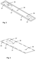
- the housing 1 shown in a sectional side view for a weighing device consists of a base plate 3 and a housing upper part 5 connected to the base plate 3, which has a cover wall 5a and a peripheral side wall 5b.
- the upper part of the housing thus has an essentially pot-shaped or trough-shaped form. It is of course not necessary for the housing 5 or the housing upper part 5 to have an essentially cuboid shape, as is shown in 1 is shown.
- the base plate also does not have to have an essentially planar structure, but can be adapted to the structure of a support element 7 on which the housing 1 is to be mounted.
- the carrier element 7 can, for example, be part of a machine frame of a complex device, such as a multi-track weighing device.
- Components of a weighing device can be arranged on the base plate 3, for example an electromechanical force sensor for detecting a load force and other mechanical or electrical or electronic components which are intended for example for converting the load force into an electrical signal.
- the electrical signal can be an analog signal or a signal that contains digital measured values.
- the base plate 3 can also be designed as an integral part of a component of the weighing device, in particular as part of the electromechanical force sensor, which can work, for example, according to the principle of electromagnetic force compensation.
- the purpose of the housing 1 is to protect the components of the weighing device located inside the housing against environmental influences, in particular dust, dirt and moisture.
- a load carrier arm, not shown in detail, of the weighing device or of the force sensor of the weighing device must of course be led out of the interior of the housing 1 . This is done via a breakthrough 9, which is at the in 1 illustrated embodiment of the housing 1 is formed in the cover wall 5a of the upper housing part 5.
- a first labyrinth sealing part 11 is inserted into the opening 9, the upper area of which interacts with the lower area of a second labyrinth sealing part 12, which can be fastened to the load arm of the force sensor, which is not shown in detail.
- the lower area of the second labyrinth sealing part surrounds the upper area of the first labyrinth sealing part 11 without contact in order to avoid a force shunt when the load force to be detected is introduced.
- annular space 13 with a labyrinthine cross section is created, which prevents or at least reduces the penetration of dust, dirt or excessive humidity in the form of droplets etc. into the interior of the housing.
- the load arm can also be brought out on the side wall of the upper part of the housing.
- a weighing device with a plurality of load arms can also be arranged in the housing, which can be guided to the outside via one or more openings in the housing.
- the one or more load arms can also be guided outwards via the base plate 3 .
- a frame 15 which can include a plurality of struts or ribs 17 , is arranged on the base plate 3 for fastening and stabilizing the housing upper part 5 .
- a strut 17 can be provided on each longitudinal side of the base plate 3 .
- one or more struts can of course also be provided between the two outer struts 17 .
- the longitudinal struts 17 can be connected by further transverse struts (not shown).
- the upper housing part 5 is placed on the frame 15, this overlapping.
- the upper part of the housing can be connected to the frame by a screw connection using one or more screws which pass through the upper part of the housing and engage in a respective strut 17 .
- the first labyrinth sealing part 11 can simultaneously serve as a mounting part for fixing the upper housing part 5 to the frame 15 .
- the lower area of the essentially cylindrical first labyrinth sealing part 11 has a thread which engages in a complementary thread in the frame or in the relevant strut 17 .
- the upper housing part 5 is pressed with its cover wall 5a against the upper side of the relevant strut. The housing upper part 5 is thus subjected to a vertically acting contact pressure.
- the frame 15 or the struts 17 can be connected to the base plate 3 by a screw connection.
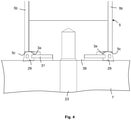
- a screw connection In 1 only a single screw connection is shown for clarification, with a screw 19 passing through the base plate 3 from below and engaging in a vertically extending part of an associated strut 17 which has a bore 21 with an internal thread for this purpose.
- a screw connection can also be provided for fastening the housing 1 to the carrier element 7 . From this one is in 1 also only a single screw 23 is shown schematically, which passes through the carrier element 7 from below and engages in a threaded hole in the underside of the base plate 3 .
- the plug-in connection 25 has contacts, not shown in detail, which can be contacted by means of a plug, which are accessible through a corresponding access opening 27 which is formed in the carrier element 7 .
- the contacting itself can of course be done by means of a plug or other suitable means.
- the base plate 3 can also have an opening through which corresponding electrical lines can be routed into the interior of the housing.
- a sealing element 29 is provided, which is arranged circumferentially on the lower outer edge of the base plate 3 .
- This ring-shaped sealing element 29 consists of a sufficiently flexible, elastic sealing material, for example a plastic such as silicone.
- the ring-shaped sealing element 29 is not arranged between the underside of the upper part of the housing and the upper side of the base plate, as in the case of previously customary housings for a weighing device, in order merely to produce a sealing effect between these two elements. Rather, the annular sealing element 29, as from 2 visible, which is an enlarged partial section along the plane AA in 1 represents, arranged below the outer edge area of the base plate 3 and also serves to seal a space within the annular sealing element 29 and below the underside of the base plate 3 against the surface of the carrier element 7. This is also the plug-in connection 25 or an opening for the passage sealed by electrical lines in the base plate 3 from the environment (above the support element 7). This of course also applies to all other components of the housing 1 or the weighing device accommodated therein which are to be protected against environmental influences and which are provided on the underside of the base plate 3 within the annular sealing element 29 or are accessible via this housing outer surface.
- the circumferential sealing element 29 is designed in such a way that its cross section protrudes beyond the outer circumference, i.e. the essentially vertically running outside of the base plate 3, so that the lower, circumferential end face 5c of the side wall 5b also acts on the upper side of the circumferential sealing element 29 when the housing is mounted on the carrier element 7 .
- the pressing force of the end face 5c of the side wall 5b is dependent, among other things, on the geometry and the material of the sealing element 29 and the geometry of the side wall 5b.
- a sealing element 29 used with a cross section whose top is substantially flat and horizontal, the Side wall 5b is preferably designed in such a way that the lower end face 5c projects beyond the underside 3a of the base plate 3 in the outer edge region of the base plate 3. In this way it can be ensured that in the area of the contact surface of the end face 5c of the sealing element 29, a contact pressure force is generated by the sealing element 29 which is sufficient to ensure the seal, even if the underside 3a of the base plate 3 covers the inner part of the horizontally running upper side of the annular Sealing element 29 is applied and as a result the sealing element 29 is already undergoing a partial deformation or compression in the area of the impact surface of the end face 5c.
Landscapes
- Physics & Mathematics (AREA)
- General Physics & Mathematics (AREA)
- Measurement Of Force In General (AREA)
- Casings For Electric Apparatus (AREA)
- Engineering & Computer Science (AREA)
- Microelectronics & Electronic Packaging (AREA)
- Fittings On The Vehicle Exterior For Carrying Loads, And Devices For Holding Or Mounting Articles (AREA)
Description
- Die Erfindung betrifft ein Gehäuse für eine Wägevorrichtung.
- Gehäuse für Wägevorrichtungen sind in vielfältiger Form bekannt. Bekannte Gehäuse für Wägevorrichtungen bestehen häufig aus einer Bodenplatte, auf welcher die Wägevorrichtung angeordnet ist. Die Wägevorrichtung kann beispielsweise einen Sensor umfassen, der nach dem Prinzip der elektromagnetischen Kraftkompensation arbeitet. Derartige Kraftsensoren weisen üblicherweise einen Roberval-Lenkermechanismus auf, der erforderlichenfalls mit einem oder mehreren Übersetzungshebeln verbunden ist. Die zu erfassende Lastkraft wirkt auf den beweglichen Teil des Roberval-Mechanismus, der mit dem ersten Übersetzungshebel verbunden ist. Am Ende des letzten Hebels ist eine Spule angeordnet, die in einem Magnetfeld auf einer konstanten Höhenposition gehalten wird. Hierzu wird die am letzten Hebel angeordnete Spule mit einem Strom beaufschlagt, der so geregelt wird, dass bei der aktuell wirkenden Lastkraft die vorbestimmte Höhenposition des letzten Hebels konstant gehalten wird. Damit ist der Wert des Stroms durch die Spule ein Maß für die detektierte Lastkraft. Sämtliche Komponenten, die zur Erfassung der Lastkraft erforderlich sind, also der Sensor, die Regelelektronik und gegebenenfalls eine Einrichtung zur Verarbeitung des oder der erfassten Messwerte, können auf der Bodenplatte des Gehäuses angeordnet sein. Das Gehäuse ist üblicherweise mittels eines Gehäuseoberteils, das die Oberseite der Bodenplatte abdeckt, zum Schutz gegen Umwelteinflüsse, wie insbesondere Staub und Feuchtigkeit, im Wesentlichen dicht ausgebildet.
- Aus dem Gehäuse müssen jedoch einerseits ein Lastträgerarm und andererseits die Kontakte zur Abgabe der elektrischen bzw. elektronischen Messsignale herausgeführt sein. Der Lastträgerarm wird üblicherweise an der Oberseite bzw. Deckelseite des Gehäuses über einen Durchbruch herausgeführt. Der Durchbruch wird mittels einer Dichtung ebenfalls gegen Umwelteinflüsse abgedichtet. Als Dichtung kommen dabei insbesondere Labyrinthdichtungen in Frage, wobei ein erstes Dichtungsteil im Durchbruch des Gehäuses oder, den Durchbruch umgebend, an der Oberseite des Gehäuses angeordnet wird. Dieses erste Dichtungsteil wird von dem Lastträgerarm möglichst berührungsfrei durchgriffen. Der Lastträgerarm ist in diesem Fall mit einem zweiten Dichtungsteil verbunden, welches zusammen mit dem ersten Dichtungsteil einen in einem vertikalen Schnitt labyrinthartigen Ringraum ausbildet. Hierdurch wird eine berührungsfreie und damit keinerlei Kraftnebenschluss bewirkende Abdichtung des Durchbruchs im Gehäuse zur Durchführung des Lastträgerarms erreicht.
- Kabeldurchführungen oder Steckkontakte für das Übertragen der elektrischen Messsignale aus dem Gehäuse können an der Unterseite des Gehäuses, das heißt an der Unterseite der Bodenplatte, vorgesehen sein.
- Solche aus einem Gehäuse und einer darin angeordneten Wägevorrichtung bestehende Einheiten werden im Rahmen der vorliegenden Beschreibung als Wägezellen bezeichnet.
- Derartige Wägezellen werden häufig in komplexe Wägeeinrichtungen, beispielsweise Mehrspurwägevorrichtungen, eingebaut. Hierzu werden die Wägezellen üblicherweise mit ihrer Bodenplatte auf einem Maschinengestell der komplexen Wägeeinrichtung montiert.
- Zur Abdichtung derartiger Gehäuse für Wägevorrichtungen, die aus einer Bodenplatte und einem topf- oder wannenförmigen Gehäuseoberteil bestehen, sind verschiedene Methoden bekannt.
- Aus der
JP 2002 107219 A - Der Erfindung liegt die Aufgabe zu Grunde, ein Gehäuse für eine Wägevorrichtung zu schaffen, bei dem der Innenraum des Gehäuses zwischen einer Bodenplatte und einem Gehäuseoberteil auf einfache Weise und langzeitstabil gegenüber der Umgebung abgedichtet ist. Gleichzeitig soll das Gehäuse auf einfache Weise mit der Bodenplatte verbunden werden.
- Die Erfindung löst diese Aufgabe mit den Merkmalen des Patentanspruchs 1.
- Das erfindungsgemäße Gehäuse für eine Wägevorrichtung, das mit einem Trägerelement verbindbar ist, weist eine Bodenplatte auf, auf der die Wägevorrichtung montierbar ist oder welche mit der Wägevorrichtung oder einer Komponente der Wägevorrichtung einstückig ausgebildet ist. An der Unterseite des Gehäuses ist ein umlaufendes elastisches Dichtelement angeordnet. Das Dichtelement ist so ausgebildet, dass ein umlaufender Ringspalt zwischen dem äußeren Umfangsbereich der Unterseite der Bodenplatte und der Oberfläche des Trägerelements bei einem Montieren des Gehäuses auf die Oberfläche mit einer definierten, auf die Unterseite der Bodenplatte und die Oberseite des Trägerelements wirkenden Anpresskraft abgedichtet wird. Damit sind Kabeldurchführungen durch die Bodenplatte in das Maschinengestell oder elektrische Kontakte, die an der Unterseite der Bodenplatte vorgesehen sind, im montierten Zustand von Gehäuse und Trägerelement gegen Umwelteinflüsse geschützt.
- Das Dichtelement ist dabei so ausgebildet, dass es bei der Montage durch die Beaufschlagung mit der Anpresskraft zwischen der Unterseite der Bodenplatte und der Oberfläche des Trägerelements elastisch deformiert wird. Das Dichtelement besteht aus einem elastischen Material, beispielsweise aus einem elastischen Kunststoff, wie Silikon. Die Elastizität des Materials und die Geometrie des Dichtelements können dabei so aufeinander abgestimmt werden, dass eine ausreichende Dichtwirkung gewährleistet ist. Das Material des Dichtelements kann dem Anwendungsfall angepasst sein. Beispielsweise kann bei Anwendungsfällen im Lebensmittelbereich ein Material verwendet werden, das eine entsprechende Eignung oder Zulassung durch die zuständigen Behörden besitzt.
- Des Weiteren kann ein magnetisch- und oder elektrisch leitendes Material für das Dichtungselement verwendet werden, um die Dichtung zusätzlich gegenüber elektromechanischen Strahlungen dicht zu gestalten und die elektromagnetische Verträglichkeit der im Gehäuse vorgesehene Wägevorrichtung bzw. der aus dem Gehäuse und der Wägevorrichtung bestehende Wägezelle, zumindest im montierten Zustand von Gehäuse und Trägerelement, zu gewährleisten.
- Erfindungsgemäß ist zur Montage des Gehäuseoberteils ein Rahmen mit der Bodenplatte verbunden oder einstückig mit dieser ausgebildet. Das Gehäuseoberteil ist in diesem Fall mit dem Rahmen verbindbar, dass eine für die Dichtwirkung ausreichende Anpresskraft für das Anpressen der Stirnseite der Seitenwandung des Gehäuseoberteils gegen das Dichtelement erzeugbar ist.
- Damit ergibt sich der Vorteil, dass ein relativ dünnwandiges Material für das Gehäuseoberteil verwendet werden kann. Die erforderliche Stabilität des Gehäuses wird im montierten Zustand durch den zusätzlichen Rahmen erreicht.
- Weitere Ausführungsformen der Erfindung ergeben sich aus den Unteransprüchen. Die Erfindung wird nachfolgend anhand eines in der Zeichnung dargestellten Ausführungsbeispiels näher erläutert. In der Zeichnung zeigen
- Fig. 1
- einen Schnitt durch die vertikale Längsmittelebene durch ein auf einem Trägerelement montiertes Gehäuse für eine Wägevorrichtung nach der Erfindung;
- Fig. 2
- einen Schnitt entlang der Ebene A-A durch die Wägevorrichtung in
Fig. 1 . - Das in
Fig. 1 in einer geschnittenen Seitenansicht dargestellte Gehäuse 1 für eine nicht näher dargestellte Wägevorrichtung besteht aus einer Bodenplatte 3 und einem mit der Bodenplatte 3 verbundenen Gehäuseoberteil 5, welches eine Deckelwandung 5a und eine umlaufende Seitenwandung 5b aufweist. Das Gehäuseoberteil besitzt damit eine im Wesentlichen topfförmige oder wannenförmige Form. Dabei ist es selbstverständlich nicht erforderlich, dass das Gehäuse 5 bzw. das Gehäuseoberteil 5 eine im Wesentlichen quaderförmige Form aufweist, wie dies inFig. 1 dargestellt ist. Die Bodenplatte muss auch nicht eine im Wesentlichen ebene Struktur aufweisen, sondern kann der Struktur eines Trägerelements 7 angepasst sein, auf dem das Gehäuse 1 montiert werden soll. Bei dem Trägerelement 7 kann es sich beispielsweise um ein Teil eines Maschinengestells einer komplexen Vorrichtung handeln, wie beispielsweise einer Mehrspurwägevorrichtung. - Auf der Bodenplatte 3 können in der Zeichnung nicht näher dargestellte Komponenten einer Wägevorrichtung angeordnet sein, beispielsweise ein elektromechanischer Kraftsensor zur Erfassung einer Lastkraft und weitere mechanische oder elektrische bzw. elektronische Komponenten, die beispielsweise zur Umsetzung der Lastkraft in ein elektrisches Signal bestimmt sind. Bei dem elektrischen Signal kann es sich um ein analoges Signal handeln oder auch um ein Signal, welches digitale Messwerte beinhaltet.
- Die Bodenplatte 3 kann auch als integraler Bestandteil einer Komponente der Wägevorrichtung ausgebildet sein, insbesondere als Bestandteil des elektromechanischen Kraftsensors, der beispielsweise nach dem Prinzip der elektromagnetischen Kraftkompensation arbeiten kann.
- Das Gehäuse 1 dient dabei dem Zweck, die im Gehäuseinneren vorhandenen Komponenten der Wägevorrichtung gegen Umwelteinflüsse, insbesondere Staub, Schmutz und Feuchtigkeit zu schützen.
- Ein nicht näher dargestellter Lastträgerarm der Wägevorrichtung bzw. des Kraftsensors der Wägevorrichtung muss selbstverständlich aus dem Gehäuseinneren des Gehäuses 1 herausgeführt werden. Dies erfolgt über einen Durchbruch 9, der bei der in
Fig. 1 dargestellten Ausführungsform des Gehäuses 1 in der Deckelwandung 5a des Gehäuseoberteils 5 ausgebildet ist. - In den Durchbruch 9 ist ein erstes Labyrinthdichtungsteil 11 eingesetzt, dessen oberer Bereich mit dem unteren Bereich eines zweiten Labyrinthdichtungsteils 12 zusammenwirkt, welches an dem nicht näher dargestellten Lastarm des Kraftsensors befestigt sein kann. Das zweite Labyrinthdichtungsteil umgreift mit seinem unteren Bereich den oberen Bereich des ersten Labyrinthdichtungsteils 11 berührungslos, um einen Kraftnebenschluss bei der Einleitung der zu erfassenden Lastkraft zu vermeiden. Zwischen dem unteren Bereich des zweiten Labyrinthdichtungsteils und dem oberen Bereich des ersten Labyrinthdichtungsteils ist somit ein im Querschnitt labyrinthartiger Ringraum 13 geschaffen, welcher das Eindringen von Staub, Schmutz oder übermäßiger Luftfeuchtigkeit in Form von Tröpfchen etc. in das Gehäuseinnere vermeidet oder zumindest reduziert.
- An dieser Stelle sei erwähnt, dass der Lastarm auch an der Seitenwandung des Gehäuseüberteils herausgeführt sein kann. Im Gehäuse kann auch eine Wägevorrichtung mit mehreren Lastarmen angeordnet sein, die über einen oder mehrere Durchbrüche im Gehäuse nach außen geführt sein können. Der eine oder die mehreren Lastarme können auch über die Bodenplatte 3 nach außen geführt sein.
- Auf der Bodenplatte 3 ist zur Befestigung und Stabilisierung des Gehäuseoberteils 5 ein Rahmen 15 angeordnet, der mehrere Streben oder Rippen 17 umfassen kann. Beispielsweise kann an jeder Längsseite der Bodenplatte 3 eine Strebe 17 vorgesehen sein. Zusätzlich können selbstverständlich auch zwischen den beiden äußeren Streben 17 ein oder mehrere Streben vorgesehen sein. Die längs verlaufenden Streben 17 können dabei durch weitere, quer verlaufende Streben (nicht dargestellt) verbunden sein.
- Wie aus
Fig. 1 ersichtlich, ist das Gehäuseoberteil 5 auf den Rahmen 15, diesen übergreifend, aufgesetzt. Das Gehäuseoberteil kann dabei durch eine Schraubverbindung über eine oder mehrere Schrauben, welche das Gehäuseoberteil durchgreifen und in jeweils eine Strebe 17 eingreifen, mit dem Rahmen verbunden werden. - Zusätzlich oder stattdessen kann das erste Labyrinthdichtungsteil 11 gleichzeitig als Montageteil zur Fixierung des Gehäuseoberteils 5 am Rahmen 15 dienen. Hierzu kann, wie in
Fig. 1 dargestellt, der untere Bereich des im Wesentlichen zylindrischen ersten Labyrinthdichtungsteils 11 ein Gewinde aufweisen, welches in ein komplementäres Gewinde im Rahmen bzw. in der betreffenden Strebe 17 eingreift. Auf diese Weise wird das Gehäuseoberteil 5 mit seiner Deckelwandung 5a gegen die Oberseite der betreffenden Strebe gepresst. Damit erfährt das Gehäuseoberteil 5 eine vertikal wirkende Anpresskraft. - Der Rahmen 15 bzw. die Streben 17 können durch Schraubverbindung mit der Bodenplatte 3 verbunden sein. In
Fig. 1 ist zur Verdeutlichung lediglich eine einzige Schraubverbindung dargestellt, wobei eine Schraube 19 die Bodenplatte 3 von unten durchgreift und in einen vertikal verlaufenden Teil einer zugeordneten Strebe 17 eingreift, die hierzu eine Bohrung 21 mit einem Innengewinde aufweist. - Zur Befestigung des Gehäuses 1 auf dem Trägerelement 7 kann ebenfalls eine Schraubverbindung vorgesehen sein. Von dieser ist in
Fig. 1 ebenfalls nur eine einzige Schraube 23 schematisch dargestellt, welche das Trägerelement 7 von unten durchgreift und in eine Gewindebohrung in der Unterseite der Bodenplatte 3 eingreift. - Die in
Fig. 1 dargestellte Bodenplatte 3 weist des Weiteren eine Steckverbindung 25 auf, die ebenfalls nur schematisch dargestellt ist. Die Steckverbindung 25 weist nicht näher dargestellte Kontakte auf, die mittels eines Steckers kontaktierbar sind, welche durch eine entsprechende Zugangsöffnung 27 zugänglich sind, die im Trägerelement 7 ausgebildet ist. Das Kontaktieren selbst kann selbstverständlich mittels eines Steckers oder anderer geeigneter Mittel erfolgen. - Die Bodenplatte 3 kann anstelle der Steckverbindung 25 oder zusätzlich zu der Steckverbindung 25 auch einen Durchbruch aufweisen, durch welchen entsprechende elektrische Leitungen in das Gehäuseinnere geführt werden können.
- Um den Gehäuseinnenraum des Gehäuses 1 und auch das Gehäuse 1 gegenüber dem Trägerelement 7 abzudichten, ist ein Dichtelement 29 vorgesehen, welches umlaufend an der unteren Außenkante der Bodenplatte 3 angeordnet ist. Dieses ringförmige Dichtelement 29 besteht aus einem ausreichend flexiblen, elastischen Dichtungsmaterial, beispielsweise aus einem Kunststoff wie Silikon.
- Das ringförmige Dichtelement 29 ist nicht wie bei bisher üblichen Gehäusen für eine Wägevorrichtung zwischen der Unterseite des Gehäuseoberteils und der Oberseite der Bodenplatte angeordnet, um lediglich eine Dichtwirkung zwischen diesen beiden Elementen zu erzeugen. Vielmehr ist das ringförmige Dichtelement 29, wie aus
Fig. 2 ersichtlich, die einen vergrößerten Teilschnitt entlang der Ebene A-A inFig. 1 darstellt, unterhalb des äußeren Randbereichs der Bodenplatte 3 angeordnet und dient zusätzlich auch der Abdichtung eines Raums innerhalb des ringförmigen Dichtelements 29 und unterhalb der Unterseite der Bodenplatte 3 gegen die Oberfläche des Trägerelements 7. Damit ist auch die Steckverbindung 25 bzw. ein Durchbruch für das Hindurchführen von elektrischen Leitungen in der Bodenplatte 3 gegenüber der Umgebung (oberhalb des Trägerelements 7) abgedichtet. Dies gilt selbstverständlich auch für alle anderen gegen Umwelteinflüsse zu schützenden Bestandteile des Gehäuses 1 bzw. der darin aufgenommenen Wägevorrichtung, die an der Unterseite der Bodenplatte 3 innerhalb des ringförmigen Dichtelements 29 vorgesehen oder über diese Gehäuseaußenfläche zugänglich sind. - Das umlaufende Dichtelement 29 ist, wie aus Fig. 24 ersichtlich, so ausgebildet, dass es mit seinem Querschnitt über den äußeren Umfang, das heißt die im Wesentlichen vertikal verlaufende Außenseite der Bodenplatte 3, hinausragt, so dass die untere, umlaufende Stirnseite 5c der Seitenwandung 5b im montierten Zustand des Gehäuses auf dem Trägerelement 7 ebenfalls die Oberseite des umlaufenden Dichtelements 29 beaufschlagt. Die Anpresskraft der Stirnseite 5c der Seitenwandung 5b ist dabei unter anderem abhängig von der Geometrie und dem Material des Dichtelements 29 und der Geometrie der Seitenwandung 5b.
- Wird, wie bei der Ausführungsform in
Fig. 2 , ein Dichtelement 29 mit einem Querschnitt verwendet, dessen Oberseite im Wesentlichen eben ist und horizontal verläuft, so wird die Seitenwandung 5b vorzugsweise so ausgebildet, dass die untere Stirnseite 5c über die Unterseite 3a der Bodenplatte 3 im äußeren Randbereich der Bodenplatte 3 hinausragt. Hierdurch kann sichergestellt werden, dass auch im Bereich der Beaufschlagungsfläche der Stirnseite 5c des Dichtelements 29 durch das Dichtelement 29 eine Anpresskraft erzeugt wird, die zur Gewährleistung der Abdichtung ausreicht, selbst wenn die Unterseite 3a der Bodenplatte 3 den inneren Teil der horizontal verlaufenden Oberseite des ringförmigen Dichtelements 29 beaufschlagt und hierdurch das Dichtelement 29 auch im Bereich der Beaufschlagungsfläche der Stirnseite 5c bereits eine teilweise Deformation bzw. Kompression erfährt. - Damit wird eine sichere Abdichtung der Bodenplatte 3 gegenüber dem Trägerelement 7 erreicht, sowie des Weiteren eine sichere Abdichtung des Gehäuseoberteils 5 gegenüber der Bodenplatte 3 und damit eine sichere Abdichtung des Inneren des Gehäuses 1 gegenüber der Umgebung.
-
- 1
- Gehäuse
- 3
- Bodenplatte,
- 3a
- Unterseite
- 5
- Gehäuseoberteil
- 5a
- Deckelwandung
- 5b
- Seitenwandung
- 5c
- untere Stirnseite
- 7
- Trägerelement
- 9
- Durchbruch
- 11
- erstes Labyrinthdichtungsteil
- 12
- zweites Labyrinthdichtungsteil
- 13
- Ringraum
- 15
- Rahmen
- 17
- Strebe
- 19
- Schraube
- 21
- Bohrung
- 23
- Schraube
- 25
- Steckverbindung
- 27
- Zugangsöffnung
- 29
- Dichtelement
- 31
- Trägerteil
- 38
- Schraube
- 39
- Flanschvorsprung
Claims (10)
- Gehäuse für eine Wägevorrichtung, welches mit einem Trägerelement verbindbar ist,(a) mit einer Bodenplatte (3), auf welcher die Wägevorrichtung montierbar ist oder welche mit der Wägevorrichtung oder einer Komponente der Wägevorrichtung einstückig ausgebildet ist,(b) und mit einem mit der Bodenplatte (3) verbindbaren Gehäuseoberteil (5) mit einer Deckelwandung (5a) und einer umlaufenden Seitenwandung (5b),(c) und mit einem von einer Dichtung (11, 12) abgedichteten Durchbruch (9) in der Wandung (5a, 5b) des Gehäuseoberteils (5) zur Durchführung eines Lastträgerarms,
dadurch gekennzeichnet,(d) dass zur Montage des Gehäuseoberteils (5) ein Rahmen (15) mit der Bodenplatte (3) verbunden oder einstückig mit dieser ausgebildet ist, und(e) dass das Gehäuseoberteil (5) mittels eines ersten Dichtungsteils (11) am Rahmen (15) fixiert ist. - Gehäuse nach Anspruch 1, dadurch gekennzeichnet, dass die Dichtung (11, 12) eine Labyrinthdichtung ist, wobei das erste Dichtungsteil als ein erstes Labyrinthdichtungsteil (11) ausgeführt und im Durchbruch (9) angeordnet ist.
- Gehäuse nach Anspruch 1 oder 2, dadurch gekennzeichnet, dass der Rahmen mehrere Streben oder Rippen (17) umfasst.
- Gehäuse nach einem der vorigen Ansprüche, dadurch gekennzeichnet, dass das erste Dichtungsteil (11) ein Gewinde aufweist, welches zur Befestigung des Gehäuseoberteils (5) in ein dazu komplementäres Gewinde im Rahmen (15) bzw. einer Strebe (17) des Rahmens (15) eingreift.
- Gehäuse nach einem der vorigen Ansprüche, dadurch gekennzeichnet, dass das Gehäuseoberteil (5) auf den Rahmen (15), diesen übergreifend, aufgesetzt ist.
- Gehäuse nach einem der vorigen Ansprüche, dadurch gekennzeichnet, dass das Gehäuseoberteil (5) mit seiner Deckelwandung (5a) durch die Fixierung mit dem ersten Dichtungsteil (11) gegen die Oberseite einer Strebe (17) des Rahmens (15) gepresst wird.
- Gehäuse nach einem der vorigen Ansprüche, dadurch gekennzeichnet, dass der Rahmen (15) bzw. die Streben (17) durch eine Schraubverbindung mit der Bodenplatte (3) verbunden sind.
- Waage mit einem Gehäuse nach einem der vorigen Ansprüche.
- Verfahren zum Befestigen eines Waagengehäuses nach einem der Ansprüche 1 bis 7, umfassen folgenden Verfahrensschritt:a) Aufsetzen des Gehäuseoberteils (5) auf den Rahmen (15);b) Fixierung des Gehäuseoberteils (5) am Rahmen (15) mittels des ersten Labyrinthdichtungsteils (11).
- Verfahren nach dem vorhergehenden Anspuch, dadurch gekennzeichnet, dass das ersten Labyrinthdichtungsteil (11) ein Gewinde aufweist, welches zur Fixierung des Gehäuseoberteils (5) in ein dazu komplementäres Gewinde im Rahmen (15) eingreift.
Priority Applications (1)
| Application Number | Priority Date | Filing Date | Title |
|---|---|---|---|
| PL18199829T PL3447457T3 (pl) | 2013-05-31 | 2014-05-27 | Obudowa do urządzenia ważącego |
Applications Claiming Priority (2)
| Application Number | Priority Date | Filing Date | Title |
|---|---|---|---|
| DE102013105647.4A DE102013105647B4 (de) | 2013-05-31 | 2013-05-31 | Gehäuse für eine Wägevorrichtung |
| EP14401066.7A EP2808660B1 (de) | 2013-05-31 | 2014-05-27 | Gehäuse für eine Wägevorrichtung |
Related Parent Applications (2)
| Application Number | Title | Priority Date | Filing Date |
|---|---|---|---|
| EP14401066.7A Division EP2808660B1 (de) | 2013-05-31 | 2014-05-27 | Gehäuse für eine Wägevorrichtung |
| EP14401066.7A Division-Into EP2808660B1 (de) | 2013-05-31 | 2014-05-27 | Gehäuse für eine Wägevorrichtung |
Publications (2)
| Publication Number | Publication Date |
|---|---|
| EP3447457A1 EP3447457A1 (de) | 2019-02-27 |
| EP3447457B1 true EP3447457B1 (de) | 2022-02-16 |
Family
ID=50928046
Family Applications (2)
| Application Number | Title | Priority Date | Filing Date |
|---|---|---|---|
| EP18199829.5A Active EP3447457B1 (de) | 2013-05-31 | 2014-05-27 | Gehäuse für eine wägevorrichtung |
| EP14401066.7A Active EP2808660B1 (de) | 2013-05-31 | 2014-05-27 | Gehäuse für eine Wägevorrichtung |
Family Applications After (1)
| Application Number | Title | Priority Date | Filing Date |
|---|---|---|---|
| EP14401066.7A Active EP2808660B1 (de) | 2013-05-31 | 2014-05-27 | Gehäuse für eine Wägevorrichtung |
Country Status (6)
| Country | Link |
|---|---|
| US (1) | US9103712B2 (de) |
| EP (2) | EP3447457B1 (de) |
| JP (1) | JP5913438B2 (de) |
| CN (1) | CN104215314B (de) |
| DE (1) | DE102013105647B4 (de) |
| PL (2) | PL2808660T3 (de) |
Families Citing this family (9)
| Publication number | Priority date | Publication date | Assignee | Title |
|---|---|---|---|---|
| DE102013105647B4 (de) * | 2013-05-31 | 2014-12-11 | Wipotec Wiege- Und Positioniersysteme Gmbh | Gehäuse für eine Wägevorrichtung |
| DE202016105471U1 (de) * | 2016-09-30 | 2016-11-10 | Wipotec Wiege- Und Positioniersysteme Gmbh | Abdeckhaube |
| EP3441729A1 (de) * | 2017-08-09 | 2019-02-13 | Koninklijke Philips N.V. | Lastbestimmungsvorrichtung und zugehöriges herstellungsverfahren |
| US12038319B2 (en) | 2017-09-28 | 2024-07-16 | Pelstar, Llc | Scale calibration device and method of use |
| US20210018358A1 (en) * | 2017-09-28 | 2021-01-21 | Pelstar, Llc | Scale calibration device and method of use |
| US11624648B2 (en) | 2019-07-09 | 2023-04-11 | Pelstar, Llc | Systems and methods for scale calibration |
| WO2021181602A1 (ja) * | 2020-03-12 | 2021-09-16 | 大和製衡株式会社 | シール構造及びそれを備えた計量装置 |
| CN112429421B (zh) * | 2020-12-02 | 2022-03-25 | 上海元捷供应链管理有限公司 | 一种用于危险化学品的存储运输装置 |
| CN115077678A (zh) * | 2022-04-26 | 2022-09-20 | 核工业理化工程研究院 | 天平封闭壳的调平及紧固基座结构及其调节方法 |
Family Cites Families (16)
| Publication number | Priority date | Publication date | Assignee | Title |
|---|---|---|---|---|
| DE2808660A1 (de) * | 1978-03-01 | 1979-09-06 | Skf Kugellagerfabriken Gmbh | Kuehlvorrichtung insbesondere fuer verbrennungskraftmaschinen in kraftfahrzeugen |
| US4416343A (en) | 1981-05-13 | 1983-11-22 | Sartorius Gmbh | Electromechanical weigher |
| DE3208015C2 (de) * | 1981-05-13 | 1986-11-06 | Sartorius GmbH, 3400 Göttingen | Elektromechanische Waage |
| JPH03285125A (ja) * | 1990-03-31 | 1991-12-16 | Anritsu Corp | 防水秤 |
| JPH0731144Y2 (ja) * | 1989-09-22 | 1995-07-19 | 株式会社クボタ | 防塵形台はかり |
| JPH06160163A (ja) * | 1992-11-25 | 1994-06-07 | Tokyo Electric Co Ltd | 電子秤 |
| JP3701855B2 (ja) * | 2000-09-29 | 2005-10-05 | アンリツ産機システム株式会社 | 電子天秤 |
| CN2919207Y (zh) * | 2006-05-16 | 2007-07-04 | 常州市宏事达电气制造有限公司 | 电子防水秤结构改进 |
| CN200996865Y (zh) * | 2006-12-28 | 2007-12-26 | 罗以久 | 防水计重秤外壳 |
| DE102007014711A1 (de) * | 2007-03-23 | 2008-09-25 | Mettler-Toledo Ag | Verfahren zur Überwachung und/oder Bestimmung des Zustandes einer Kraftmessvorrichtung und Kraftmessvorrichtung |
| CN101329195A (zh) * | 2007-06-22 | 2008-12-24 | 上海友声衡器有限公司 | 防水称重显示器 |
| DE102009013545B4 (de) * | 2009-03-19 | 2013-02-21 | Wipotec Wiege- Und Positioniersysteme Gmbh | Dichtmechanismus |
| CN201408064Y (zh) * | 2009-03-23 | 2010-02-17 | 惠而邦电子衡器(昆山)有限公司 | 一种防水秤 |
| JP5469002B2 (ja) * | 2010-06-29 | 2014-04-09 | 新光電子株式会社 | 電磁力平衡式計量装置 |
| CN202304992U (zh) * | 2011-10-28 | 2012-07-04 | 惠而邦电子衡器(昆山)有限公司 | 一种电子秤的防水透气结构 |
| DE102013105647B4 (de) * | 2013-05-31 | 2014-12-11 | Wipotec Wiege- Und Positioniersysteme Gmbh | Gehäuse für eine Wägevorrichtung |
-
2013
- 2013-05-31 DE DE102013105647.4A patent/DE102013105647B4/de not_active Expired - Fee Related
-
2014
- 2014-05-27 EP EP18199829.5A patent/EP3447457B1/de active Active
- 2014-05-27 PL PL14401066T patent/PL2808660T3/pl unknown
- 2014-05-27 EP EP14401066.7A patent/EP2808660B1/de active Active
- 2014-05-27 PL PL18199829T patent/PL3447457T3/pl unknown
- 2014-05-28 US US14/289,470 patent/US9103712B2/en active Active
- 2014-05-30 CN CN201410336416.0A patent/CN104215314B/zh active Active
- 2014-06-02 JP JP2014114145A patent/JP5913438B2/ja active Active
Also Published As
| Publication number | Publication date |
|---|---|
| EP2808660A8 (de) | 2015-03-25 |
| JP5913438B2 (ja) | 2016-04-27 |
| DE102013105647B4 (de) | 2014-12-11 |
| EP2808660A1 (de) | 2014-12-03 |
| US9103712B2 (en) | 2015-08-11 |
| JP2014235170A (ja) | 2014-12-15 |
| CN104215314A (zh) | 2014-12-17 |
| PL2808660T3 (pl) | 2019-06-28 |
| EP3447457A1 (de) | 2019-02-27 |
| CN104215314B (zh) | 2017-04-12 |
| US20140353050A1 (en) | 2014-12-04 |
| EP2808660B1 (de) | 2018-11-28 |
| PL3447457T3 (pl) | 2022-06-20 |
| DE102013105647A1 (de) | 2014-12-04 |
Similar Documents
| Publication | Publication Date | Title |
|---|---|---|
| EP3447457B1 (de) | Gehäuse für eine wägevorrichtung | |
| EP2687823B2 (de) | Vorrichtung zur Erfassung und Verarbeitung von Sensormesswerten und/oder zur Steuerung von Aktuatoren | |
| DE4405408C1 (de) | Metallgehäuse für den Einbau elektronischer Bauteile | |
| DE102014118044B4 (de) | Elektronische Steuervorrichtung für ein Kraftfahrzeug unter Verwendung eines Kopplungsgliedes sowie Verfahren zu deren Herstellung | |
| DE112017005927T5 (de) | Motor und elektrische servolenkvorrichtung | |
| DE102010002765A1 (de) | Gehäusegrundelement eines mehrteiligen Gehäuses und Verfahren zur Montage eines Gehäuses | |
| EP3202040A1 (de) | Näherungssensoranordnung | |
| DE202014102022U1 (de) | Kapazitiver Sensor | |
| EP3220116B1 (de) | Kraftsensorvorrichtung | |
| WO2023030771A1 (de) | Vorrichtung zur aufnahme eines displays für ein feldgerät der automatisierungstechnik | |
| EP3309967B1 (de) | Kapazitive schalt-vorrichtung | |
| DE10313828A1 (de) | Kraftmesszelle | |
| DE102008008336A1 (de) | Verfahren zur Positionsbestimmung und zur Positionierung eines abgedeckten Sensorelements einer Sensoranordnung sowie Sensoranordnung mit einem entsprechend positionierten Sensorelement | |
| DE102015012740A1 (de) | Fahrzeugsteuergerät | |
| EP0825448A2 (de) | Messvorrichtung für eine metallgekapselte gasisolierte Hochspannungsanlage | |
| DE102013200014A1 (de) | Elektronische Vorrichtung | |
| DE102020106774B4 (de) | Sensor und sensorbefestigungsstruktur | |
| DE102019126082B4 (de) | Hydraulischer Aktor mit Mitteln zur Befestigung eines Drucksensors ohne eigenes Gehäuse | |
| WO2009112066A1 (de) | Vorrichtung zur anordnung von umfeldsensoren in einem fahrzeug | |
| DE102005022399B4 (de) | Vorrichtung zur Befestigung für einen mindestens einen Sensor aufweisenden Schaltungsträger | |
| EP1891409B1 (de) | Dehnungssensor | |
| DE102020100332A1 (de) | Kapazitives Kraftfahrzeugbediensystem | |
| EP4677965A1 (de) | Displayeinheit für ein feldgerät der automatisierungstechnik | |
| DE102016213775A1 (de) | Winkelsensor zum Erfassen eines Drehwinkels | |
| DE102021126095A1 (de) | Feldgerät |
Legal Events
| Date | Code | Title | Description |
|---|---|---|---|
| PUAI | Public reference made under article 153(3) epc to a published international application that has entered the european phase |
Free format text: ORIGINAL CODE: 0009012 |
|
| STAA | Information on the status of an ep patent application or granted ep patent |
Free format text: STATUS: THE APPLICATION HAS BEEN PUBLISHED |
|
| AC | Divisional application: reference to earlier application |
Ref document number: 2808660 Country of ref document: EP Kind code of ref document: P |
|
| AK | Designated contracting states |
Kind code of ref document: A1 Designated state(s): AL AT BE BG CH CY CZ DE DK EE ES FI FR GB GR HR HU IE IS IT LI LT LU LV MC MK MT NL NO PL PT RO RS SE SI SK SM TR |
|
| STAA | Information on the status of an ep patent application or granted ep patent |
Free format text: STATUS: REQUEST FOR EXAMINATION WAS MADE |
|
| 17P | Request for examination filed |
Effective date: 20190702 |
|
| RBV | Designated contracting states (corrected) |
Designated state(s): AL AT BE BG CH CY CZ DE DK EE ES FI FR GB GR HR HU IE IS IT LI LT LU LV MC MK MT NL NO PL PT RO RS SE SI SK SM TR |
|
| GRAP | Despatch of communication of intention to grant a patent |
Free format text: ORIGINAL CODE: EPIDOSNIGR1 |
|
| STAA | Information on the status of an ep patent application or granted ep patent |
Free format text: STATUS: GRANT OF PATENT IS INTENDED |
|
| INTG | Intention to grant announced |
Effective date: 20211028 |
|
| GRAS | Grant fee paid |
Free format text: ORIGINAL CODE: EPIDOSNIGR3 |
|
| GRAA | (expected) grant |
Free format text: ORIGINAL CODE: 0009210 |
|
| STAA | Information on the status of an ep patent application or granted ep patent |
Free format text: STATUS: THE PATENT HAS BEEN GRANTED |
|
| AC | Divisional application: reference to earlier application |
Ref document number: 2808660 Country of ref document: EP Kind code of ref document: P |
|
| AK | Designated contracting states |
Kind code of ref document: B1 Designated state(s): AL AT BE BG CH CY CZ DE DK EE ES FI FR GB GR HR HU IE IS IT LI LT LU LV MC MK MT NL NO PL PT RO RS SE SI SK SM TR |
|
| REG | Reference to a national code |
Ref country code: GB Ref legal event code: FG4D Free format text: NOT ENGLISH |
|
| REG | Reference to a national code |
Ref country code: CH Ref legal event code: EP |
|
| REG | Reference to a national code |
Ref country code: DE Ref legal event code: R096 Ref document number: 502014016116 Country of ref document: DE |
|
| REG | Reference to a national code |
Ref country code: AT Ref legal event code: REF Ref document number: 1469164 Country of ref document: AT Kind code of ref document: T Effective date: 20220315 |
|
| REG | Reference to a national code |
Ref country code: IE Ref legal event code: FG4D Free format text: LANGUAGE OF EP DOCUMENT: GERMAN |
|
| REG | Reference to a national code |
Ref country code: LT Ref legal event code: MG9D |
|
| REG | Reference to a national code |
Ref country code: NL Ref legal event code: MP Effective date: 20220216 |
|
| PG25 | Lapsed in a contracting state [announced via postgrant information from national office to epo] |
Ref country code: SE Free format text: LAPSE BECAUSE OF FAILURE TO SUBMIT A TRANSLATION OF THE DESCRIPTION OR TO PAY THE FEE WITHIN THE PRESCRIBED TIME-LIMIT Effective date: 20220216 Ref country code: RS Free format text: LAPSE BECAUSE OF FAILURE TO SUBMIT A TRANSLATION OF THE DESCRIPTION OR TO PAY THE FEE WITHIN THE PRESCRIBED TIME-LIMIT Effective date: 20220216 Ref country code: PT Free format text: LAPSE BECAUSE OF FAILURE TO SUBMIT A TRANSLATION OF THE DESCRIPTION OR TO PAY THE FEE WITHIN THE PRESCRIBED TIME-LIMIT Effective date: 20220616 Ref country code: NO Free format text: LAPSE BECAUSE OF FAILURE TO SUBMIT A TRANSLATION OF THE DESCRIPTION OR TO PAY THE FEE WITHIN THE PRESCRIBED TIME-LIMIT Effective date: 20220516 Ref country code: NL Free format text: LAPSE BECAUSE OF FAILURE TO SUBMIT A TRANSLATION OF THE DESCRIPTION OR TO PAY THE FEE WITHIN THE PRESCRIBED TIME-LIMIT Effective date: 20220216 Ref country code: LT Free format text: LAPSE BECAUSE OF FAILURE TO SUBMIT A TRANSLATION OF THE DESCRIPTION OR TO PAY THE FEE WITHIN THE PRESCRIBED TIME-LIMIT Effective date: 20220216 Ref country code: HR Free format text: LAPSE BECAUSE OF FAILURE TO SUBMIT A TRANSLATION OF THE DESCRIPTION OR TO PAY THE FEE WITHIN THE PRESCRIBED TIME-LIMIT Effective date: 20220216 Ref country code: ES Free format text: LAPSE BECAUSE OF FAILURE TO SUBMIT A TRANSLATION OF THE DESCRIPTION OR TO PAY THE FEE WITHIN THE PRESCRIBED TIME-LIMIT Effective date: 20220216 Ref country code: BG Free format text: LAPSE BECAUSE OF FAILURE TO SUBMIT A TRANSLATION OF THE DESCRIPTION OR TO PAY THE FEE WITHIN THE PRESCRIBED TIME-LIMIT Effective date: 20220516 |
|
| PG25 | Lapsed in a contracting state [announced via postgrant information from national office to epo] |
Ref country code: LV Free format text: LAPSE BECAUSE OF FAILURE TO SUBMIT A TRANSLATION OF THE DESCRIPTION OR TO PAY THE FEE WITHIN THE PRESCRIBED TIME-LIMIT Effective date: 20220216 Ref country code: GR Free format text: LAPSE BECAUSE OF FAILURE TO SUBMIT A TRANSLATION OF THE DESCRIPTION OR TO PAY THE FEE WITHIN THE PRESCRIBED TIME-LIMIT Effective date: 20220517 Ref country code: FI Free format text: LAPSE BECAUSE OF FAILURE TO SUBMIT A TRANSLATION OF THE DESCRIPTION OR TO PAY THE FEE WITHIN THE PRESCRIBED TIME-LIMIT Effective date: 20220216 |
|
| PG25 | Lapsed in a contracting state [announced via postgrant information from national office to epo] |
Ref country code: IS Free format text: LAPSE BECAUSE OF FAILURE TO SUBMIT A TRANSLATION OF THE DESCRIPTION OR TO PAY THE FEE WITHIN THE PRESCRIBED TIME-LIMIT Effective date: 20220617 |
|
| PG25 | Lapsed in a contracting state [announced via postgrant information from national office to epo] |
Ref country code: SM Free format text: LAPSE BECAUSE OF FAILURE TO SUBMIT A TRANSLATION OF THE DESCRIPTION OR TO PAY THE FEE WITHIN THE PRESCRIBED TIME-LIMIT Effective date: 20220216 Ref country code: SK Free format text: LAPSE BECAUSE OF FAILURE TO SUBMIT A TRANSLATION OF THE DESCRIPTION OR TO PAY THE FEE WITHIN THE PRESCRIBED TIME-LIMIT Effective date: 20220216 Ref country code: RO Free format text: LAPSE BECAUSE OF FAILURE TO SUBMIT A TRANSLATION OF THE DESCRIPTION OR TO PAY THE FEE WITHIN THE PRESCRIBED TIME-LIMIT Effective date: 20220216 Ref country code: EE Free format text: LAPSE BECAUSE OF FAILURE TO SUBMIT A TRANSLATION OF THE DESCRIPTION OR TO PAY THE FEE WITHIN THE PRESCRIBED TIME-LIMIT Effective date: 20220216 Ref country code: DK Free format text: LAPSE BECAUSE OF FAILURE TO SUBMIT A TRANSLATION OF THE DESCRIPTION OR TO PAY THE FEE WITHIN THE PRESCRIBED TIME-LIMIT Effective date: 20220216 Ref country code: CZ Free format text: LAPSE BECAUSE OF FAILURE TO SUBMIT A TRANSLATION OF THE DESCRIPTION OR TO PAY THE FEE WITHIN THE PRESCRIBED TIME-LIMIT Effective date: 20220216 |
|
| REG | Reference to a national code |
Ref country code: DE Ref legal event code: R097 Ref document number: 502014016116 Country of ref document: DE |
|
| PG25 | Lapsed in a contracting state [announced via postgrant information from national office to epo] |
Ref country code: AL Free format text: LAPSE BECAUSE OF FAILURE TO SUBMIT A TRANSLATION OF THE DESCRIPTION OR TO PAY THE FEE WITHIN THE PRESCRIBED TIME-LIMIT Effective date: 20220216 |
|
| PLBE | No opposition filed within time limit |
Free format text: ORIGINAL CODE: 0009261 |
|
| STAA | Information on the status of an ep patent application or granted ep patent |
Free format text: STATUS: NO OPPOSITION FILED WITHIN TIME LIMIT |
|
| REG | Reference to a national code |
Ref country code: BE Ref legal event code: MM Effective date: 20220531 |
|
| 26N | No opposition filed |
Effective date: 20221117 |
|
| PG25 | Lapsed in a contracting state [announced via postgrant information from national office to epo] |
Ref country code: MC Free format text: LAPSE BECAUSE OF FAILURE TO SUBMIT A TRANSLATION OF THE DESCRIPTION OR TO PAY THE FEE WITHIN THE PRESCRIBED TIME-LIMIT Effective date: 20220216 Ref country code: LU Free format text: LAPSE BECAUSE OF NON-PAYMENT OF DUE FEES Effective date: 20220527 |
|
| PG25 | Lapsed in a contracting state [announced via postgrant information from national office to epo] |
Ref country code: SI Free format text: LAPSE BECAUSE OF FAILURE TO SUBMIT A TRANSLATION OF THE DESCRIPTION OR TO PAY THE FEE WITHIN THE PRESCRIBED TIME-LIMIT Effective date: 20220216 |
|
| PG25 | Lapsed in a contracting state [announced via postgrant information from national office to epo] |
Ref country code: IE Free format text: LAPSE BECAUSE OF NON-PAYMENT OF DUE FEES Effective date: 20220527 Ref country code: FR Free format text: LAPSE BECAUSE OF NON-PAYMENT OF DUE FEES Effective date: 20220531 |
|
| PG25 | Lapsed in a contracting state [announced via postgrant information from national office to epo] |
Ref country code: BE Free format text: LAPSE BECAUSE OF NON-PAYMENT OF DUE FEES Effective date: 20220531 |
|
| REG | Reference to a national code |
Ref country code: AT Ref legal event code: MM01 Ref document number: 1469164 Country of ref document: AT Kind code of ref document: T Effective date: 20220527 |
|
| PG25 | Lapsed in a contracting state [announced via postgrant information from national office to epo] |
Ref country code: AT Free format text: LAPSE BECAUSE OF NON-PAYMENT OF DUE FEES Effective date: 20220527 |
|
| PG25 | Lapsed in a contracting state [announced via postgrant information from national office to epo] |
Ref country code: HU Free format text: LAPSE BECAUSE OF FAILURE TO SUBMIT A TRANSLATION OF THE DESCRIPTION OR TO PAY THE FEE WITHIN THE PRESCRIBED TIME-LIMIT; INVALID AB INITIO Effective date: 20140527 |
|
| PG25 | Lapsed in a contracting state [announced via postgrant information from national office to epo] |
Ref country code: MK Free format text: LAPSE BECAUSE OF FAILURE TO SUBMIT A TRANSLATION OF THE DESCRIPTION OR TO PAY THE FEE WITHIN THE PRESCRIBED TIME-LIMIT Effective date: 20220216 Ref country code: CY Free format text: LAPSE BECAUSE OF FAILURE TO SUBMIT A TRANSLATION OF THE DESCRIPTION OR TO PAY THE FEE WITHIN THE PRESCRIBED TIME-LIMIT Effective date: 20220216 |
|
| PG25 | Lapsed in a contracting state [announced via postgrant information from national office to epo] |
Ref country code: MT Free format text: LAPSE BECAUSE OF FAILURE TO SUBMIT A TRANSLATION OF THE DESCRIPTION OR TO PAY THE FEE WITHIN THE PRESCRIBED TIME-LIMIT Effective date: 20220216 |
|
| PGFP | Annual fee paid to national office [announced via postgrant information from national office to epo] |
Ref country code: PL Payment date: 20250516 Year of fee payment: 12 Ref country code: DE Payment date: 20250428 Year of fee payment: 12 |
|
| PGFP | Annual fee paid to national office [announced via postgrant information from national office to epo] |
Ref country code: IT Payment date: 20250530 Year of fee payment: 12 |
|
| PGFP | Annual fee paid to national office [announced via postgrant information from national office to epo] |
Ref country code: CH Payment date: 20250601 Year of fee payment: 12 |
|
| PG25 | Lapsed in a contracting state [announced via postgrant information from national office to epo] |
Ref country code: TR Free format text: LAPSE BECAUSE OF FAILURE TO SUBMIT A TRANSLATION OF THE DESCRIPTION OR TO PAY THE FEE WITHIN THE PRESCRIBED TIME-LIMIT Effective date: 20220216 |
|
| PGFP | Annual fee paid to national office [announced via postgrant information from national office to epo] |
Ref country code: GB Payment date: 20260302 Year of fee payment: 13 |