EP3447532A2 - Hybridsensor mit kamera und lidar sowie bewegtobjekt - Google Patents
Hybridsensor mit kamera und lidar sowie bewegtobjekt Download PDFInfo
- Publication number
- EP3447532A2 EP3447532A2 EP18189682.0A EP18189682A EP3447532A2 EP 3447532 A2 EP3447532 A2 EP 3447532A2 EP 18189682 A EP18189682 A EP 18189682A EP 3447532 A2 EP3447532 A2 EP 3447532A2
- Authority
- EP
- European Patent Office
- Prior art keywords
- information
- coordinate information
- sensor
- data
- map
- Prior art date
- Legal status (The legal status is an assumption and is not a legal conclusion. Google has not performed a legal analysis and makes no representation as to the accuracy of the status listed.)
- Granted
Links
Images








Classifications
-
- G—PHYSICS
- G01—MEASURING; TESTING
- G01S—RADIO DIRECTION-FINDING; RADIO NAVIGATION; DETERMINING DISTANCE OR VELOCITY BY USE OF RADIO WAVES; LOCATING OR PRESENCE-DETECTING BY USE OF THE REFLECTION OR RERADIATION OF RADIO WAVES; ANALOGOUS ARRANGEMENTS USING OTHER WAVES
- G01S17/00—Systems using the reflection or reradiation of electromagnetic waves other than radio waves, e.g. lidar systems
- G01S17/02—Systems using the reflection of electromagnetic waves other than radio waves
- G01S17/06—Systems determining position data of a target
- G01S17/08—Systems determining position data of a target for measuring distance only
-
- G—PHYSICS
- G01—MEASURING; TESTING
- G01S—RADIO DIRECTION-FINDING; RADIO NAVIGATION; DETERMINING DISTANCE OR VELOCITY BY USE OF RADIO WAVES; LOCATING OR PRESENCE-DETECTING BY USE OF THE REFLECTION OR RERADIATION OF RADIO WAVES; ANALOGOUS ARRANGEMENTS USING OTHER WAVES
- G01S17/00—Systems using the reflection or reradiation of electromagnetic waves other than radio waves, e.g. lidar systems
- G01S17/86—Combinations of lidar systems with systems other than lidar, radar or sonar, e.g. with direction finders
-
- G—PHYSICS
- G01—MEASURING; TESTING
- G01S—RADIO DIRECTION-FINDING; RADIO NAVIGATION; DETERMINING DISTANCE OR VELOCITY BY USE OF RADIO WAVES; LOCATING OR PRESENCE-DETECTING BY USE OF THE REFLECTION OR RERADIATION OF RADIO WAVES; ANALOGOUS ARRANGEMENTS USING OTHER WAVES
- G01S17/00—Systems using the reflection or reradiation of electromagnetic waves other than radio waves, e.g. lidar systems
- G01S17/88—Lidar systems specially adapted for specific applications
- G01S17/93—Lidar systems specially adapted for specific applications for anti-collision purposes
- G01S17/931—Lidar systems specially adapted for specific applications for anti-collision purposes of land vehicles
-
- G—PHYSICS
- G01—MEASURING; TESTING
- G01S—RADIO DIRECTION-FINDING; RADIO NAVIGATION; DETERMINING DISTANCE OR VELOCITY BY USE OF RADIO WAVES; LOCATING OR PRESENCE-DETECTING BY USE OF THE REFLECTION OR RERADIATION OF RADIO WAVES; ANALOGOUS ARRANGEMENTS USING OTHER WAVES
- G01S7/00—Details of systems according to groups G01S13/00, G01S15/00, G01S17/00
- G01S7/48—Details of systems according to groups G01S13/00, G01S15/00, G01S17/00 of systems according to group G01S17/00
- G01S7/481—Constructional features, e.g. arrangements of optical elements
- G01S7/4817—Constructional features, e.g. arrangements of optical elements relating to scanning
-
- G—PHYSICS
- G01—MEASURING; TESTING
- G01S—RADIO DIRECTION-FINDING; RADIO NAVIGATION; DETERMINING DISTANCE OR VELOCITY BY USE OF RADIO WAVES; LOCATING OR PRESENCE-DETECTING BY USE OF THE REFLECTION OR RERADIATION OF RADIO WAVES; ANALOGOUS ARRANGEMENTS USING OTHER WAVES
- G01S7/00—Details of systems according to groups G01S13/00, G01S15/00, G01S17/00
- G01S7/48—Details of systems according to groups G01S13/00, G01S15/00, G01S17/00 of systems according to group G01S17/00
- G01S7/483—Details of pulse systems
- G01S7/486—Receivers
- G01S7/4865—Time delay measurement, e.g. time-of-flight measurement, time of arrival measurement or determining the exact position of a peak
Definitions
- the technical field of the present disclosure relates to a sensor module which combines and processes information obtained by a camera and information obtained by a Lidar.
- a mobile robot which determines a route and moves by itself.
- the mobile robot needs to recognize the position on the space while generating a map for a space where the robot is moving.
- the mobile robot travels by dead reckoning using a gyroscope and an encoder provided in a driving motor and analyzes distance information using a Lidar sensor provided at an upper portion or analyzes an image using a camera to generate a map.
- the mobile robot corrects errors accumulated by driving information from the gyroscope and the encoder using point cloud information on surrounding environments obtained by a Lidar sensor.
- a time of flight based Lidar measures a time of a light signal which is emitted and then reflected and measures a distance from a reflector using a speed of light.
- the mobile robot may obtain image information on the surrounding environment obtained from the camera.
- SLAM simultaneous localization and mapping
- the graph based SLMA represents the position and the motion of the robot by a node and an edge of a graph.
- a node is a position of a robot or an artificial landmark at a specific timing.
- the edge is a relationship between two nodes and refers to a constraint on a space between two nodes.
- the measured edge includes errors. Therefore, when a traveling distance of the robot is increased and the number of nodes is increased, errors may be accumulated during a process of predicting the position.
- a major object of the present disclosure is to generate composite data by mapping distance information on an obstacle obtained through a Lidar sensor to image information on an obstacle obtained through an image sensor and interpolate the distance information of the composite data based on an intensity of a pixel to converge the Lidar sensor and the image sensor.
- Another object of the present invention is to provide a map which covers a broader area within a predetermined time under a predetermined condition, by generating a key frame for a node using scan information, calculating an odometry edge between consecutive nodes, and updating the key frame to predict a local map, and by detecting a loop closure edge between inconsecutive nodes for a set of updated key frames and correcting a position of the node based on the odometry edge and the loop closure edge to predict a global map.
- a hybrid sensor includes: a first sensor which obtains first data for a target, a second sensor which obtains second data for a target, and a processing unit which generates composite data obtained by mapping the first data and the second data.
- a moving object includes: a hybrid sensor which obtains first data related to a target by means of a first sensor, obtains second data related to the target by means of a second sensor, and generates composite data obtained by mapping the first data and the second data, a map generator which analyzes the first data or the composite data to generate a map related to a surrounding environment, and a moving device implemented to move the moving object based on the map.
- the first data may include first coordinate information which is two-dimensionally represented and intensity information related to the first coordinate information
- the second data may include second coordinate information which is two-dimensionally represented and depth information related to the second coordinate information
- the composite data may include space coordinate information which is three-dimensionally represented and the intensity information
- the processing unit may compare the first coordinate information and the second coordinate information with respect to a space region where a first space area seen from a position where the first sensor is installed and a second space area seen from a position where the second sensor is installed overlap to map corresponding coordinate information.
- the processing unit may generate the composite data based on (i) depth information corresponding to common coordinate information corresponding to the second coordinate information, among the first coordinate information and (ii) intensity information corresponding to the common coordinate information.
- the processing unit may predict first predicted depth information related to non-common information which does not correspond to second coordinate information, among first coordinate information, using (i) depth information corresponding to common coordinate information and (ii) intensity information corresponding to the common coordinate information.
- the processing unit may determine similarity between
- the predicting unit may predict second predicted depth information related to the non-common coordinate information using (i) intensity information of the non-common coordinate information, (ii) intensity information of the common coordinate information, and (iii) the first predicted depth information.
- the processing unit may update the composite data based on the first predicted depth information related to the non-common coordinate information.
- the hybrid sensor may operate both the first sensor and the second sensor for a target which is closer than a predetermined distance to generate composite data and selectively operate the first sensor or the second sensor for a target which is disposed farther than a predetermined distance to obtain data.
- the map generator may analyze the first data, the second data, or the composite data to generate a key frame related to a node, calculate an odometry edge between consecutive nodes, and update the key frame to predict a local map and detect a loop closure edge between inconsecutive nodes with respect to a set of the updated key frame and correct the position of the node based on the odometry edge and the loop closure edge to generate a global map.
- the map generator may rotate or move the first data, the second data, or the composite data to perform scan matching or measures the odometry information of the moving object to calculate the odometry edge and correct an error between the odometry edge predicted based on a predicted value of the node and the measured odometry edge through the scan matching.
- the map generator may filter the key frame when a predetermined condition for a movement distance of the moving object is satisfied.
- the map generator may predict the global map for a set of the updated key frame when a predetermined condition for the movement distance of the mobile robot or a change of the surrounding environment is satisfied.
- the map generator may correct an error of the key frame using uncertainty propagation with respect to the specified key frame.
- the map generator may extract a first candidate for a key frame located within a predetermined distance using a Mahalanobis distance.
- the map generator may compare a key frame of the first candidate group with a key frame obtained during a predetermined time period to extract a second candidate group related to a key frame matching in a predetermined probable range.
- the map generator may extract a third candidate group related to a key frame matching a predetermined consistence range from the second candidate group using a consistence checking algorithm.
- the map generator may correct an error of the odometry edge and an error of the loop closure edge by a graph optimizing technique.
- composite data is generated by mapping distance information on an obstacle obtained by means of a Lidar sensor to image information on an obstacle obtained by means of an image sensor and the distance information of the composite data is interpolated based on an intensity of a pixel to converge data of the Lidar sensor and data of the image sensor.
- a hybrid sensor according to an exemplary embodiment in which a Lidar and a camera are converted may be applied to a product which requires distance measurement such as a flight object such as a drone, a moving object such as a vehicle, or small home appliance.
- FIG. 1 is a block diagram illustrating a moving object.
- a moving object 1 includes a hybrid sensor 10, a mag generator 20, and a moving device 20.
- the moving object 1 may omit some components among various components which are exemplarily illustrated in FIG. 1 or may further include other component.
- the moving object may further include a cleaning unit.
- the moving object 1 refers to a device designed to be movable from a specific position to another position according to a predetermined method and moves from the specific position to another position using a moving unit such as wheels, rails, or walking legs.
- the moving object 1 may collect external information using a sensor and then move according to the collected information or move using a separate manipulating unit by a user.
- Examples of the moving object 1 include robot cleaners, toy cars, mobile robots for industrial or military purposes.
- the moving object 1 may travel using wheels or walk using one or more legs, or may be implemented by a combination thereof.
- the robot cleaner is a device which sucks foreign matters such as dust accumulated on a floor while traveling a cleaning space to automatically clean the cleaning space. Differently from a normal cleaner which moves by an external force provided by a user, the robot cleaner moves using external information or a predetermined moving pattern to clean the cleaning space.
- the robot cleaner may automatically move using a predetermined pattern or detect an external obstacles using a detecting sensor and then moves as it is detected. Further, the robot cleaner may move in accordance with a signal transmitted from a remote control device which is manipulated by the user.
- the moving device 30 calculates a traveling route based on a distance to the target or detects an obstacle to move the moving object. Odometry information such as a revolution, a gradient, or a rotational amount may be obtained from an encoder connected to the moving device or an inertial measurement unit.
- the IMU may be implemented by an acceleration sensor or a gyro sensor.
- a position of the moving object 1 may be represented by a three-dimensional vector.
- the three-dimensional vector may be represented by an X coordinate and a Y coordinate from an origin of a reference coordinate system and an angle formed by an X axis of a robot coordinate system and an X axis of the reference coordinate system.
- FIG. 2 is a block diagram illustrating a hybrid sensor.
- the hybrid sensor 10 includes a first sensor 110, a second sensor 120, and a processing unit 130.
- the hybrid sensor 10 may omit some components among various components which are exemplarily illustrated in FIG. 2 or may additionally include other component.
- the first sensor 110 obtains first data for a target.
- the first sensor 110 may be an image sensor which obtains image information on an obstacle.
- the first data includes first coordinate information which is two-dimensionally represented and intensity information related to the first coordinate information.
- the intensity information has a predetermined range according to a bit value set for a pixel.
- the camera includes an image sensor which converts light entering through a lens into an electrical image signal.
- the image sensor may be implemented by a charged coupled device (CCD) or a complementary metal-oxide semiconductor (CMOS).
- CCD charged coupled device
- CMOS complementary metal-oxide semiconductor
- the second sensor 120 obtains second data for a target.
- the second sensor 120 may be a Lidar sensor which obtains distance information on an obstacle.
- the second data includes second coordinate information which is two-dimensionally represented and depth information related to the second coordinate information.
- the Lidar sensor is a device which transmits a laser signal, measures a returning time of the reflected signal, and measures a distance to a reflector using a speed of light.
- the laser signal is converted into an electrical signal by a photo diode.
- the laser signal may have a predetermined wavelength band.
- the Lidar may use a wavelength of an infrared ray region.
- the Lidar sensor may operate by a time of flight (TOF) manner.
- TOF time of flight
- a laser emits a pulsed or square wave signal to measure a time when reflection pulses or square wave signals from objects within a measurement range reach a receiver to measure a distance between an object to be measured and a sensor.
- the Lidar sensor includes an optical transceiver and a distance measuring unit.
- the optical transceiver transmits a laser signal and receives a reflected signal.
- the optical transceiver emits light to a target by a start control signal and receives light which is reflected from the target to convert the light into an electrical signal.
- the optical transceiver outputs the electrical signal during a predetermined detecting time.
- the optical transceiver may include a signal converter.
- the signal converter is connected to a photo diode of the optical transceiver and a trans impedance amplifier is connected to the signal converter.
- the light source emits light to the target based on a predetermined sampling period.
- the sampling period may be set by a controller of a distance measuring apparatus.
- the sampling period is a time when the optical transceiver emits light and receives reflected light, and converts the light into an electrical signal in accordance with the start control signal.
- the optical transceiver may repeatedly perform this operation in a next sampling period.
- the photo diode receives light reflected from the target to convert the light into an electrical signal.
- the distance measuring unit includes one or more signal discriminators which convert an electrical signal to measure an exact timing and output a stop control signal.
- the distance measuring unit uses a signal discriminator to convert the electrical signal such that a signal point having a maximum signal magnitude has a predetermined magnitude, adjust an magnitude of the converted electrical signal, and detect a timing having the predetermined magnitude.
- the signal discriminator converts the electrical signal to generate a stop control signal.
- the signal discriminator receives the electrical signal from the photo diode or the trans impedance amplifier.
- the received electrical signal that is, an input signal rises or falls by the reflected light.
- the signal discriminator exactly measures a target timing for the input signal to output the electrical signal.
- the distance measuring unit may include one or more time to digital converters which convert the difference of two hours into the digital value.
- the input signal of the time to digital converter may be a pulse shape of the same signal source or may be an edge of other signal source.
- the distance measuring apparatus may calculate the time difference based on a rising edge or a falling edge of the start control signal and a rising edge or a falling edge of the stop control signal.
- the distance measuring unit calculates the pulse width with respect to the rising edge or the falling edge of the stop control signal and adds the factor value which is applied to a function of the pulse width versus walk error to a time of flight which has not been corrected.
- the distance measuring apparatus corrects the time of flight using a pulse width of the reflected signal to calculate the exact time of flight.
- the processing unit 130 receives first data from the first sensor 110 and receives second data from the second sensor 120.
- the processing unit 130 generates composite data obtained by mapping the first data and the second data.
- the composite data includes space coordinate information which is three-dimensionally represented and intensity information.
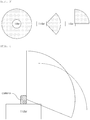
- FIG. 3 is a view illustrating a viewing angle of a Lidar sensor.
- the Lidar sensor may scan a specifically plane or a specific dimension at an omnidirectional viewing angle.
- the Lidar sensor may scan with a viewing angle within a specific direction and a specific angle range.
- the Lidar sensor illustrated on a left side of FIG. 1 scans in all directions and the Lidar sensor illustrated at a center and a right side of FIG. 1 sweeps in a vertical direction.
- a specific product may sweep between +/- 45 degrees or 0 to 90 degrees.
- FIG. 4 is a view illustrating an overlapping area of a viewing angle of a camera and a viewing angle of a Lidar sensor.
- the Lidar sensor and the camera may be installed such that a viewing angle of the camera and a viewing angle of the Lidar sensor overlap as much as possible.
- the camera may be disposed above the Lidar. Since a wide angle camera has a larger viewing angle (for example, 190 degrees) than that of a normal camera, the overlapping area with the viewing angle of the Lidar sensor may be increased.
- the hybrid sensor 10 maps the distance information on an obstacle obtained through the Lidar sensor to image information on an obstacle obtained through an image sensor to create composite data.
- the image information includes an intensity of a pixel.
- the processing unit 130 compares first coordinate information obtained from the first sensor 110 and second coordinate information obtained from the second sensor, with respect to a first space area seen from a position where the first sensor 110 is installed and a space area overlapping the second space area seen from a position where the second sensor 120, to map corresponding coordinate information.
- m is a pixel-mapped coordinate (common coordinate information)
- X is information on an obstacle obtained through the Lidar
- R and t are transformation attributes
- K is an image matrix (first coordinate information) obtained through a camera attached to the Lidar.
- the transformation attributes may be a transformation matrix for size transform, position transform, shape transform, and rotation.
- the transformation attributes may be a rotation matrix and a translation matrix.
- the processing unit 130 creates the composite data based on (i) depth information corresponding to common coordinate information corresponding to the second coordinate information, in the first coordinate information and (ii) intensity information corresponding to the common coordinate information.
- x, y, and z represent three-dimensional space coordinate on an obstacle in a frame of the Lidar and I represents an intensity.
- the three-dimensional space coordinate includes a two-dimensional coordinate and a distance information.
- the hybrid sensor interpolates or expands the distance information of the composite data based on the intensity of the pixel.
- the hybrid sensor 10 may densify the distance information of the composite data using an interpolation technique.
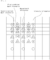
- FIG. 5 is a view illustrating composite data processed by a hybrid sensor.
- the hybrid sensor generates predicted depth information. Based on an assumption that adjacent obstacles have similar depth information, adjacent pixels have similar intensity information, and pixels having similar intensity information have similar depth information, the distance information mapped to an image area is interpolated.
- the processing unit 130 may predict first predicted depth information p1 related to non-common information which does not correspond to second coordinate information, among first coordinate information, using (i) depth information d corresponding to common coordinate information and (ii) intensity information corresponding to the common coordinate information.
- the processing unit 130 determines similarity between adjacent intensity information by comparing (i) intensity information of the non-common coordinate information and (ii) intensity information of common coordinate information present within a predetermined range from the non-common coordinate information.
- the processing unit 130 may predict first predicted depth information p1 in accordance with a similarity determining result.
- the processing unit 130 may update the composite data based on the first predicted depth information related to the non-common coordinate information.
- the processing unit 130 may predict second predicted depth information p2 related to non-common coordinate information using (i) intensity information of non-common coordinate information present in the predetermined range (ii) intensity information of common coordinate information present in the predetermined range, and (iii) the first predicted depth information p1 present within the predetermined range.
- the processing unit 130 may update the composite data based on the second predicted depth information related to the non-common coordinate information.
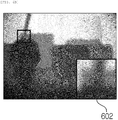
- FIGS. 6A to 6D are views illustrating data obtained by a Lidar sensor of a hybrid sensor and data obtained by an image sensor.
- the hybrid sensor needs to interpolate distance information which is not mapped after combining an image 610 in which intensity information of a pixel is represented and distance information.
- the hybrid sensor interpolates the distance information which is not mapped, based on the intensity information. Referring to images 602 and 603 in which distance information which is not mapped is interpolated only using mapped distance information in FIGS. 6B and 6C and an image 604 in which the distance information which is not mapped is interpolated based on the intensity information in FIG. 6D , it is understood that the precision of the distance information included in the composite data is improved by the distance information interpolated using the intensity information.
- FIG. 7 is a view illustrating a hybrid sensor including a plurality of cameras.
- the distance measurement may be restricted in accordance with a power of the laser and the environment.
- the hybrid sensor operates both the first sensor and the second sensor for a target which is closer than a predetermined distance to create composite data.
- the moving object may perform the measurement only using the camera.
- the hybrid sensor selectively operates the first sensor or the second sensor for a target which is disposed farther than a predetermined distance to create composite data.
- the hybrid sensor may directly measure a distance using two wide angle cameras.
- the hybrid sensor may apply a single lens camera. In an environment where noises may be easily included in odometry information, it is desirable to apply a stereo camera rather than the single lens camera.
- FIGS. 8 to 18 are views for explaining an operation of recognizing a position and generating a map of a moving object according to exemplary embodiments of the present disclosure.
- SLAM simultaneous localization and mapping
- FIG. 8 is a graph model representing information processed by simultaneous localization and mapping (SLAM) method.
- x denotes a position of a robot
- u denotes odometry information
- z denotes an observed value
- m denotes a predicted map.
- SLAM techniques such as a filter based SLAM or a graph based SLAM.
- the graph based SLMA represents the position and the motion of the robot by a node and an edge of a graph.
- a node is a position of a robot or an artificial landmark at a specific timing.
- the edge is a relationship between two nodes and refers to a constraint on a space between two nodes.
- the measured edge includes errors. Therefore, when a traveling distance of the robot is increased and the number of nodes is increased, errors may be accumulated during a process of predicting the position.
- FIG. 9 is a view illustrating a map generator.
- the map generator 20 includes a local map predicting unit 210 and a global map predicting unit 220.
- the local map predicting unit 210 and the global map predicting unit 220 may be implemented by the same or different processors.
- the map generator 20 represents a pose which is scanned by a node and calculates a relative pose between the nodes.
- the map generator 20 optimizes a position of the nodes depending on the relative pose between nodes to update the map.
- the map generator 20 finds a node value which satisfies constrains as much as possible or a node value which is minimally deviated from the constrains and optimizes a position of the node by performing a process of correcting errors in the positions of the nodes. That is, the nodes are converged to an optimal node value based on the constrain.
- the map generator 20 predicts a current position using sensor data obtained from a close region when the current position is predicted.
- a scanning period and a key frame generating period are set to be appropriate values depending on a design to be implemented and may be set to be different from each other as needed.
- the hybrid sensor 10 obtains scan information of a space where the mobile robot is located.
- the hybrid sensor 10 may obtain omnidirectional distance information or distance information of a partial region using a Lidar sensor.
- the map generator 20 may additionally obtain odometry information of a mobile robot together with the distance information.
- the map generator may obtain odometry information such as a revolution, a gradient, or a rotational amount may be obtained from an encoder connected to the moving device or an inertial measurement unit.
- the IMU may be implemented by an acceleration sensor or a gyro sensor.
- a position of the mobile robot may be represented by a three-dimensional vector.
- the three-dimensional vector may be represented by an X coordinate and a Y coordinate from an origin of a reference coordinate system and an angle formed by an X axis of a robot coordinate system and an X axis of the reference coordinate system.
- the local map predicting unit 210 generates a key frame regarding a node using scan information and calculates an odometry edge between consecutive nodes.
- the observed value between nodes has uncertainty.
- the uncertainty of the odometry edge may be represented by a covariance matrix.
- the local map predicting unit 210 stores a key frame among a plurality of scan information obtained at every scanning period.
- the scan information may be represented by a point cloud or composite data.
- the key frame includes distance information and time information.
- the local map predicting unit 210 When there is no registered key frame, the local map predicting unit 210 generates a key frame using distance information which is currently input and then predicts the local map by updating the key frame.
- the local map predicting unit 210 may perform scan matching based on the local map in which a plurality of scan information is added to improve precision.
- the local map predicting unit 210 rotates or moves the scan information to match the scan or measure the odometry information of the mobile robot to calculate the odometry edge.
- the local map predicting unit 210 corrects an error between the odometry edge predicted based on the predicted value of the node and the measured odometry edge through the scan matching.
- the global map predicting unit 220 detects a loop closure edge between inconsecutive nodes with respect to a set of the updated key frames.
- the errors of the nodes may be more precisely corrected.
- the loop closure edge forms a spatial relationship between nodes which are not temporally consecutive.
- the global map predicting unit 220 predicts a global map by correcting the position of the node based on the odometry edge and the loop closure edge.
- the global map predicting unit 220 combines local maps to extend and update the global map.
- An interface is a communication path through which transmits and receives information to and from other device.
- the other device accesses the map generating unit 20 through an interface to set a parameter.
- the map generator 20 may transmit the measured position and the map to the other device through the interface.
- FIG 10 is a view illustrating data which is scan-matched by the map generator.
- the scan information obtained by the map generator includes distance information from a fixed structure.
- the odometry errors are accumulated so that common portions do not overlap.
- the odometry errors are corrected by the scan matching which rotates and moves the scan information and calculates probability of the observed value so that a precise position of the robot may be predicted.
- FIG 11 is a view illustrating data which is filtered by the map generator.
- the scan information obtained at a specific time or in a specific position may include a noise such as a moving obstacle, which is different from the fixed structure.
- the local map which is progressively updated while the mobile robot moves may be changed to a structure which is different from an actual structure. That is, due to the moving obstacle, when the scan information obtained at different time period in the same position is scan-matched, an error may be generated in the predicted map.
- the local map predicting unit discriminates a moving obstacle and a fixed obstacle from a plurality of scan information obtained during a predetermined time period by a probable technique and compares newly obtained scan information to remove the moving obstacle from the key frame, thereby updating the local map.
- the local map is updated by removing the noise using the recent N scan information.
- the noise may be point cloud data or composite data which is modified by moving a predetermined movement distance or rotating at a predetermined rotation angle.
- the local map predicting unit may filter the key frame.
- the first condition is set based on the movement distance. For example, when the moving object moves by a predetermined distance or more from the reference point, the local map predicting unit performs the filtering to remove the noise for the moving obstacle.
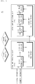
- FIG. 12 is a flowchart illustrating an operation of a map generator of predicting a global map
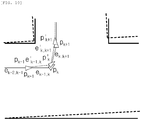
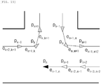
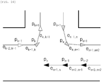
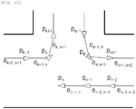
- FIGS. 13 to 17 are views illustrating data processed by the map generator.
- the global map predicting unit predicts a global map for a set of the updated key frames.
- the second condition is set based on the movement distance or the change of the surrounding environment. For example, the second condition is set such that the mobile robot travels a predetermined distance or deviates from a predetermined distance range, or a matching rate of the surrounding structure deviates from a predetermined range.
- All the recent N scan information is filtered data and has data on a fixed structure.
- the global map predicting unit stores the filtered key frames.
- step S310 the global map predicting unit corrects an error of each key frame using uncertainty propagation with respect to a specified key frame. Variables related to key frames are transmitted to a combination of other variables in the functional relationship with uncertainty.
- a first candidate group related to a key frame located within a predetermined distance is extracted using Mahalanobis distance.
- the Mahalanobis distance is a value indicating how many times the distance from the mean value is the standard deviation and represents which value is hard to generate or how strange it is by a numerical value.
- nodes p k-1 , p k , p k+1 , p m-1 , p m , p m+1 of the first candidate group which are extracted with respect to a node p n related to a recently inserted key frame are illustrated.
- step S320 the global map predicting unit compares a key frame of the first candidate group with a key frame obtained during a predetermined time period to extract a second candidate group related to a key frame matching in a predetermined probable range.
- nodes p k , p m-1 , p m , p m+1 of the second candidate group which are extracted with respect to nodes p n , p n-1 , p n-2 related to recent N key frames are illustrated.
- the global map predicting unit extracts a third candidate group related to a key frame matching a predetermined consistence range from the second candidate group using a consistence checking algorithm.
- the global map predicting unit rechecks an erroneously matched candidate.
- a maximum clique or single cluster graph partitioning technique may be applied as the consistency checking algorithm.
- FIG. 15 illustrates extracted nodes p m-1 , p m , p m+1 of the third candidate group.
- step s340 the global map predicting unit detects a loop closure edge between inconsecutive nodes with respect to the key frame belonging to the third candidate group.
- the global map predicting unit forms a spatial relationship between the recent node and the significant node.
- FIG. 16 illustrates a loop closure edge e n, m between inconsecutive nodes p n , p m .
- the global map predicting unit corrects the error of the odometry edge and the error of the loop closure edge by a graph optimizing technique.
- the global map predicting unit finds a node value which satisfies constrains as much as possible or a node value which is minimally deviated from the constrains and optimizes a position of the node by performing a process of correcting errors in the positions of the nodes. That is, the nodes are converged to an optimal node value based on the constrain.
- the error may be corrected by calculating a minimum value of a weighted sum of square for an error vector by the plurality of odometry edges and the plurality of loop closure edges.
- FIG. 17 illustrates nodes and edges for correcting an error.
- the global map predicting unit may output a global map obtained by adding the plurality of local maps.
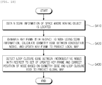
- FIG. 18 is a flowchart illustrating a map creating method of a moving object according to another exemplary embodiment of the present disclosure.
- a map creating method of a moving object may be performed by a map generator of a moving object (a mobile robot).
- step S410 the map generator obtains scan information of a space where the mobile robot is located.
- step S410 of obtaining scan information omnidirectional distance information or distance information of partial regions may be obtained using a Lidar sensor.
- step S410 of obtaining the scan information odometry information of a mobile robot may be additionally obtained together with the distance information.
- step S420 the map generator generates a key frame for a node using scan information, calculates an odometry edge between consecutive nodes, and updates the key frame to predict a local map.
- step S420 of predicting a local map the scan information rotates or moves to match the scan or measure the odometry information of the mobile robot to calculate the odometry edge.
- step S420 of predicting a local map an error between the predicted odometry edge and the predicted odometry edge is corrected based on the predicted value of the node by scan matching.
- step S420 of predicting a local map when a first condition for a movement distance of the mobile robot is satisfied, the key frame is filtered.
- step S420 of predicting a local map a moving obstacle and a fixed obstacle are discriminated from a plurality of scan information obtained during a predetermined time period by a probable technique and newly obtained scan information is compared to remove the moving obstacle from the key frame, thereby updating the local map.
- step S430 the map generator detects a loop closure edge between inconsecutive nodes for a set of the updated key frames and corrects the position of the node based on the odometry edge and the loop closure edge to predict a global map.
- step S430 of predicting a global map when a second condition for a movement distance of the mobile robot or a change of the surrounding environment is satisfied, a global map for a set of the updated key frames is predicted.
- step S430 of predicting a global map an error of each key frame is corrected using uncertainty propagation with respect to a specified key frame and a first candidate group for a key frame located within a predetermined distance is extracted using Mahalanobis distance.
- step S430 of predicting a global map a key frame of the first candidate group is compared with a key frame obtained during a predetermined time period to extract a second candidate group related to a key frame matching in a predetermined probable range.
- step S430 of predicting a global map a third candidate group related to a key frame matching a predetermined consistence range is extracted from the second candidate group using a consistence checking algorithm.
- the map generator generates a loop closure edge for at least one node among nodes belonging to the first candidate group to the third candidate group.
- step S430 of predicting a global map the error of the odometry edge and the error of the loop closure edge are corrected by a graph optimizing technique.
- a plurality of components included in the hybrid sensor and the moving object are combined to each other to be implemented by at least one module.
- the components are connected to a communication path which connects a software module or a hardware module in the apparatus to organically operate between the components.
- the components communicate with each other using one or more communication buses or signal lines.
- the hybrid sensor and the moving object may be implemented in a logic circuit by hardware, firm ware, software, or a combination thereof or may be implemented using a general purpose or special purpose computer.
- the apparatus may be implemented using hardwired device, field programmable gate ware (FPFA) or application specific integrated circuit (ASIC). Further, the apparatus may be implemented by a system on chip (SoC) including one or more processors and a controller.
- SoC system on chip
- the hybrid sensor and the moving object may be mounted in a computing device provided with a hardware element as a software, a hardware, or a combination thereof.
- the computing device may refer to various devices including all or some of a communication device for communicating with various devices and wired/wireless communication networks such as a communication modem, a memory which stores data for executing programs, and a microprocessor which executes programs to perform operations and commands.
- the operation according to the exemplary embodiment of the present disclosure may be implemented as a program command which may be executed by various computers to be recorded in a computer readable medium.
- the computer readable medium indicates an arbitrary medium which participates to provide a command to a processor for execution.
- the computer readable medium may include solely a program command, a data file, and a data structure or a combination thereof.
- the computer readable medium may include a magnetic medium, an optical recording medium, and a memory.
- the computer program may be distributed on a networked computer system so that the computer readable code may be stored and executed in a distributed manner. Functional programs, codes, and code segments for implementing the present embodiment may be easily inferred by programmers in the art to which this embodiment belongs.
Landscapes
- Engineering & Computer Science (AREA)
- Physics & Mathematics (AREA)
- Radar, Positioning & Navigation (AREA)
- Remote Sensing (AREA)
- Computer Networks & Wireless Communication (AREA)
- General Physics & Mathematics (AREA)
- Electromagnetism (AREA)
- Control Of Position, Course, Altitude, Or Attitude Of Moving Bodies (AREA)
- Traffic Control Systems (AREA)
- Radar Systems Or Details Thereof (AREA)
- Optical Radar Systems And Details Thereof (AREA)
Applications Claiming Priority (5)
| Application Number | Priority Date | Filing Date | Title |
|---|---|---|---|
| KR1020170105671A KR101981038B1 (ko) | 2017-08-21 | 2017-08-21 | 거리 측정 장치, 신호 판별기, 및 이동체 |
| KR1020170137745A KR102172602B1 (ko) | 2017-10-23 | 2017-10-23 | 라이다를 이용한 위치 인식 및 지도 작성에 관한 방법 및 장치 |
| KR1020170145577A KR102048193B1 (ko) | 2016-12-06 | 2017-11-02 | 비행시간 기반의 라이다 장치 및 이동체 |
| KR20180055953 | 2018-05-16 | ||
| KR1020180080377A KR102135560B1 (ko) | 2018-05-16 | 2018-07-11 | 카메라와 라이다를 이용한 융합 센서 및 이동체 |
Publications (3)
| Publication Number | Publication Date |
|---|---|
| EP3447532A2 true EP3447532A2 (de) | 2019-02-27 |
| EP3447532A3 EP3447532A3 (de) | 2019-05-29 |
| EP3447532B1 EP3447532B1 (de) | 2024-09-11 |
Family
ID=63311875
Family Applications (1)
| Application Number | Title | Priority Date | Filing Date |
|---|---|---|---|
| EP18189682.0A Active EP3447532B1 (de) | 2017-08-21 | 2018-08-20 | Hybridsensor mit kamera und lidar sowie bewegtobjekt |
Country Status (2)
| Country | Link |
|---|---|
| EP (1) | EP3447532B1 (de) |
| WO (1) | WO2019039733A1 (de) |
Cited By (7)
| Publication number | Priority date | Publication date | Assignee | Title |
|---|---|---|---|---|
| CN109949371A (zh) * | 2019-03-18 | 2019-06-28 | 北京智行者科技有限公司 | 一种用于激光雷达和相机数据的标定方法 |
| CN110320912A (zh) * | 2019-07-10 | 2019-10-11 | 苏州欧博智慧机器人有限公司 | 激光与视觉slam融合的agv定位导航装置及方法 |
| CN111489400A (zh) * | 2020-06-28 | 2020-08-04 | 武汉精立电子技术有限公司 | 一种基于旋转载台的线扫ccd相机图像校正方法及介质 |
| CN111552289A (zh) * | 2020-04-28 | 2020-08-18 | 苏州高之仙自动化科技有限公司 | 检测方法及虚拟雷达装置、电子设备、存储介质 |
| EP4083921A4 (de) * | 2020-10-30 | 2023-08-23 | Amicro Semiconductor Co., Ltd. | Verfahren zur erstellung lokaler punktwolkenkarten und sichtroboter |
| CN117687042A (zh) * | 2024-02-04 | 2024-03-12 | 北京理工大学前沿技术研究院 | 一种多雷达数据融合方法、系统和设备 |
| CN118544366A (zh) * | 2024-07-26 | 2024-08-27 | 广东电网有限责任公司佛山供电局 | 相机和线激光雷达融合定位方法、装置和定位系统 |
Families Citing this family (7)
| Publication number | Priority date | Publication date | Assignee | Title |
|---|---|---|---|---|
| CN109828262A (zh) * | 2019-03-15 | 2019-05-31 | 苏州天准科技股份有限公司 | 基于平面和空间特征的激光雷达与相机自动联合标定方法 |
| CN110553652B (zh) * | 2019-10-12 | 2022-06-24 | 上海高仙自动化科技发展有限公司 | 机器人多传感器融合定位方法及其应用 |
| CN113126640B (zh) * | 2019-12-31 | 2022-06-28 | 北京三快在线科技有限公司 | 用于无人机的障碍物探测方法、装置、无人机和存储介质 |
| US11706507B2 (en) | 2020-12-30 | 2023-07-18 | Waymo Llc | Systems, apparatus, and methods for generating enhanced images |
| CN113070887B (zh) * | 2021-03-24 | 2022-12-27 | 广东博智林机器人有限公司 | 天花作业机器人以及作业方法 |
| CN113552585B (zh) * | 2021-07-14 | 2023-10-31 | 浙江大学 | 一种基于卫星地图与激光雷达信息的移动机器人定位方法 |
| CN116008967B (zh) * | 2022-12-20 | 2025-08-15 | 西安电子科技大学芜湖研究院 | 一种激光回波定时游动误差校正方法及系统 |
Family Cites Families (12)
| Publication number | Priority date | Publication date | Assignee | Title |
|---|---|---|---|---|
| US8139142B2 (en) * | 2006-06-01 | 2012-03-20 | Microsoft Corporation | Video manipulation of red, green, blue, distance (RGB-Z) data including segmentation, up-sampling, and background substitution techniques |
| KR101415297B1 (ko) * | 2008-04-16 | 2014-07-07 | 삼성전자주식회사 | 로봇 지도 생성 방법 및 로봇 지도 이용 방법 및 로봇지도를 가지는 로봇 |
| KR101782057B1 (ko) * | 2010-05-03 | 2017-09-26 | 삼성전자주식회사 | 지도 생성 장치 및 방법 |
| KR101750340B1 (ko) * | 2010-11-03 | 2017-06-26 | 엘지전자 주식회사 | 로봇 청소기 및 이의 제어 방법 |
| US9251587B2 (en) * | 2013-04-05 | 2016-02-02 | Caterpillar Inc. | Motion estimation utilizing range detection-enhanced visual odometry |
| EP4016981A3 (de) * | 2013-12-24 | 2022-09-21 | Sony Depthsensing Solutions | Time of flight kamera system |
| US9948911B2 (en) * | 2014-09-05 | 2018-04-17 | Qualcomm Incorporated | Method and apparatus for efficient depth image transformation |
| US9378554B2 (en) * | 2014-10-09 | 2016-06-28 | Caterpillar Inc. | Real-time range map generation |
| JP6762148B2 (ja) * | 2015-07-09 | 2020-09-30 | パナソニック インテレクチュアル プロパティ コーポレーション オブ アメリカPanasonic Intellectual Property Corporation of America | 地図生成方法、移動ロボット及び地図生成システム |
| US10582121B2 (en) * | 2016-01-12 | 2020-03-03 | Mitsubishi Electric Research Laboratories, Inc. | System and method for fusing outputs of sensors having different resolutions |
| KR101976241B1 (ko) * | 2016-01-22 | 2019-08-28 | 경희대학교 산학협력단 | 다중로봇의 자기위치인식에 기반한 지도작성 시스템 및 그 방법 |
| SG10201700299QA (en) * | 2017-01-13 | 2018-08-30 | Otsaw Digital Pte Ltd | Three-dimensional mapping of an environment |
-
2018
- 2018-07-11 WO PCT/KR2018/007847 patent/WO2019039733A1/ko not_active Ceased
- 2018-08-20 EP EP18189682.0A patent/EP3447532B1/de active Active
Non-Patent Citations (1)
| Title |
|---|
| None |
Cited By (9)
| Publication number | Priority date | Publication date | Assignee | Title |
|---|---|---|---|---|
| CN109949371A (zh) * | 2019-03-18 | 2019-06-28 | 北京智行者科技有限公司 | 一种用于激光雷达和相机数据的标定方法 |
| CN110320912A (zh) * | 2019-07-10 | 2019-10-11 | 苏州欧博智慧机器人有限公司 | 激光与视觉slam融合的agv定位导航装置及方法 |
| CN111552289A (zh) * | 2020-04-28 | 2020-08-18 | 苏州高之仙自动化科技有限公司 | 检测方法及虚拟雷达装置、电子设备、存储介质 |
| CN111489400A (zh) * | 2020-06-28 | 2020-08-04 | 武汉精立电子技术有限公司 | 一种基于旋转载台的线扫ccd相机图像校正方法及介质 |
| EP4083921A4 (de) * | 2020-10-30 | 2023-08-23 | Amicro Semiconductor Co., Ltd. | Verfahren zur erstellung lokaler punktwolkenkarten und sichtroboter |
| US12151384B2 (en) | 2020-10-30 | 2024-11-26 | Amicro Semiconductor Co., Ltd. | Method for building a local point cloud map and vision robot |
| CN117687042A (zh) * | 2024-02-04 | 2024-03-12 | 北京理工大学前沿技术研究院 | 一种多雷达数据融合方法、系统和设备 |
| CN117687042B (zh) * | 2024-02-04 | 2024-05-17 | 北京理工大学前沿技术研究院 | 一种多雷达数据融合方法、系统和设备 |
| CN118544366A (zh) * | 2024-07-26 | 2024-08-27 | 广东电网有限责任公司佛山供电局 | 相机和线激光雷达融合定位方法、装置和定位系统 |
Also Published As
| Publication number | Publication date |
|---|---|
| EP3447532A3 (de) | 2019-05-29 |
| EP3447532B1 (de) | 2024-09-11 |
| WO2019039733A1 (ko) | 2019-02-28 |
Similar Documents
| Publication | Publication Date | Title |
|---|---|---|
| EP3447532B1 (de) | Hybridsensor mit kamera und lidar sowie bewegtobjekt | |
| KR102135560B1 (ko) | 카메라와 라이다를 이용한 융합 센서 및 이동체 | |
| KR102172602B1 (ko) | 라이다를 이용한 위치 인식 및 지도 작성에 관한 방법 및 장치 | |
| US11579298B2 (en) | Hybrid sensor and compact Lidar sensor | |
| Lee et al. | Lidar odometry survey: recent advancements and remaining challenges | |
| CN112868225B (zh) | 结合数据以构建平面图的方法和装置 | |
| US10422648B2 (en) | Methods for finding the perimeter of a place using observed coordinates | |
| JP6672212B2 (ja) | 情報処理装置、車両、情報処理方法およびプログラム | |
| JP6987797B2 (ja) | リアルタイムオンラインエゴモーション推定を有するレーザスキャナ | |
| TWI827649B (zh) | 用於vslam比例估計的設備、系統和方法 | |
| US10006772B2 (en) | Map production method, mobile robot, and map production system | |
| JP6030405B2 (ja) | 平面検出装置およびそれを備えた自律移動装置 | |
| CN117970925A (zh) | 机器人实时避障与动态路径规划方法及系统 | |
| JP6649743B2 (ja) | 一致性評価装置および一致性評価方法 | |
| JP2009193240A (ja) | 移動ロボット及び環境地図の生成方法 | |
| US20090149990A1 (en) | Method, medium, and apparatus for performing path planning of mobile robot | |
| KR20170061373A (ko) | 이동 로봇 및 그 제어 방법 | |
| KR20150144727A (ko) | 에지 기반 재조정을 이용하여 이동 로봇의 위치를 인식하기 위한 장치 및 그 방법 | |
| CN116360451B (zh) | 面向地下复杂环境中的移动机器人自主定位方法及机器人 | |
| CN112068152A (zh) | 使用3d扫描仪同时进行2d定位和2d地图创建的方法和系统 | |
| CN112506200A (zh) | 机器人定位方法、装置、机器人及存储介质 | |
| CN118613743A (zh) | Slam装置、slam攻击对策程序以及自主型移动体 | |
| WO2020181257A1 (en) | Collaborative determination of a load footprint of a robotic vehicle | |
| AU2021273605B2 (en) | Multi-agent map generation | |
| CA3135442A1 (en) | Simultaneous localization and mapping |
Legal Events
| Date | Code | Title | Description |
|---|---|---|---|
| PUAI | Public reference made under article 153(3) epc to a published international application that has entered the european phase |
Free format text: ORIGINAL CODE: 0009012 |
|
| STAA | Information on the status of an ep patent application or granted ep patent |
Free format text: STATUS: REQUEST FOR EXAMINATION WAS MADE |
|
| 17P | Request for examination filed |
Effective date: 20180820 |
|
| AK | Designated contracting states |
Kind code of ref document: A2 Designated state(s): AL AT BE BG CH CY CZ DE DK EE ES FI FR GB GR HR HU IE IS IT LI LT LU LV MC MK MT NL NO PL PT RO RS SE SI SK SM TR |
|
| AX | Request for extension of the european patent |
Extension state: BA ME |
|
| PUAL | Search report despatched |
Free format text: ORIGINAL CODE: 0009013 |
|
| AK | Designated contracting states |
Kind code of ref document: A3 Designated state(s): AL AT BE BG CH CY CZ DE DK EE ES FI FR GB GR HR HU IE IS IT LI LT LU LV MC MK MT NL NO PL PT RO RS SE SI SK SM TR |
|
| AX | Request for extension of the european patent |
Extension state: BA ME |
|
| RIC1 | Information provided on ipc code assigned before grant |
Ipc: G01S 17/08 20060101ALI20190425BHEP Ipc: G01S 7/481 20060101ALI20190425BHEP Ipc: G01S 7/486 20060101ALI20190425BHEP Ipc: G01S 17/93 20060101ALI20190425BHEP Ipc: G01S 17/02 20060101AFI20190425BHEP |
|
| STAA | Information on the status of an ep patent application or granted ep patent |
Free format text: STATUS: EXAMINATION IS IN PROGRESS |
|
| 17Q | First examination report despatched |
Effective date: 20210715 |
|
| GRAP | Despatch of communication of intention to grant a patent |
Free format text: ORIGINAL CODE: EPIDOSNIGR1 |
|
| STAA | Information on the status of an ep patent application or granted ep patent |
Free format text: STATUS: GRANT OF PATENT IS INTENDED |
|
| RIC1 | Information provided on ipc code assigned before grant |
Ipc: G01S 17/931 20200101ALI20240328BHEP Ipc: G01S 17/86 20200101ALI20240328BHEP Ipc: G01S 7/4865 20200101ALI20240328BHEP Ipc: G01S 7/486 20060101ALI20240328BHEP Ipc: G01S 7/481 20060101ALI20240328BHEP Ipc: G01S 17/93 20060101ALI20240328BHEP Ipc: G01S 17/08 20060101ALI20240328BHEP Ipc: G01S 17/02 20060101AFI20240328BHEP |
|
| INTG | Intention to grant announced |
Effective date: 20240430 |
|
| GRAS | Grant fee paid |
Free format text: ORIGINAL CODE: EPIDOSNIGR3 |
|
| GRAA | (expected) grant |
Free format text: ORIGINAL CODE: 0009210 |
|
| STAA | Information on the status of an ep patent application or granted ep patent |
Free format text: STATUS: THE PATENT HAS BEEN GRANTED |
|
| AK | Designated contracting states |
Kind code of ref document: B1 Designated state(s): AL AT BE BG CH CY CZ DE DK EE ES FI FR GB GR HR HU IE IS IT LI LT LU LV MC MK MT NL NO PL PT RO RS SE SI SK SM TR |
|
| REG | Reference to a national code |
Ref country code: GB Ref legal event code: FG4D |
|
| REG | Reference to a national code |
Ref country code: CH Ref legal event code: EP |
|
| REG | Reference to a national code |
Ref country code: DE Ref legal event code: R096 Ref document number: 602018074192 Country of ref document: DE |
|
| REG | Reference to a national code |
Ref country code: IE Ref legal event code: FG4D |
|
| REG | Reference to a national code |
Ref country code: LT Ref legal event code: MG9D |
|
| PG25 | Lapsed in a contracting state [announced via postgrant information from national office to epo] |
Ref country code: NO Free format text: LAPSE BECAUSE OF FAILURE TO SUBMIT A TRANSLATION OF THE DESCRIPTION OR TO PAY THE FEE WITHIN THE PRESCRIBED TIME-LIMIT Effective date: 20241211 |
|
| REG | Reference to a national code |
Ref country code: NL Ref legal event code: MP Effective date: 20240911 |
|
| PG25 | Lapsed in a contracting state [announced via postgrant information from national office to epo] |
Ref country code: GR Free format text: LAPSE BECAUSE OF FAILURE TO SUBMIT A TRANSLATION OF THE DESCRIPTION OR TO PAY THE FEE WITHIN THE PRESCRIBED TIME-LIMIT Effective date: 20241212 Ref country code: FI Free format text: LAPSE BECAUSE OF FAILURE TO SUBMIT A TRANSLATION OF THE DESCRIPTION OR TO PAY THE FEE WITHIN THE PRESCRIBED TIME-LIMIT Effective date: 20240911 |
|
| PG25 | Lapsed in a contracting state [announced via postgrant information from national office to epo] |
Ref country code: BG Free format text: LAPSE BECAUSE OF FAILURE TO SUBMIT A TRANSLATION OF THE DESCRIPTION OR TO PAY THE FEE WITHIN THE PRESCRIBED TIME-LIMIT Effective date: 20240911 |
|
| PG25 | Lapsed in a contracting state [announced via postgrant information from national office to epo] |
Ref country code: LV Free format text: LAPSE BECAUSE OF FAILURE TO SUBMIT A TRANSLATION OF THE DESCRIPTION OR TO PAY THE FEE WITHIN THE PRESCRIBED TIME-LIMIT Effective date: 20240911 |
|
| PG25 | Lapsed in a contracting state [announced via postgrant information from national office to epo] |
Ref country code: HR Free format text: LAPSE BECAUSE OF FAILURE TO SUBMIT A TRANSLATION OF THE DESCRIPTION OR TO PAY THE FEE WITHIN THE PRESCRIBED TIME-LIMIT Effective date: 20240911 |
|
| PG25 | Lapsed in a contracting state [announced via postgrant information from national office to epo] |
Ref country code: RS Free format text: LAPSE BECAUSE OF FAILURE TO SUBMIT A TRANSLATION OF THE DESCRIPTION OR TO PAY THE FEE WITHIN THE PRESCRIBED TIME-LIMIT Effective date: 20241211 Ref country code: ES Free format text: LAPSE BECAUSE OF FAILURE TO SUBMIT A TRANSLATION OF THE DESCRIPTION OR TO PAY THE FEE WITHIN THE PRESCRIBED TIME-LIMIT Effective date: 20240911 |
|
| PG25 | Lapsed in a contracting state [announced via postgrant information from national office to epo] |
Ref country code: RS Free format text: LAPSE BECAUSE OF FAILURE TO SUBMIT A TRANSLATION OF THE DESCRIPTION OR TO PAY THE FEE WITHIN THE PRESCRIBED TIME-LIMIT Effective date: 20241211 Ref country code: NO Free format text: LAPSE BECAUSE OF FAILURE TO SUBMIT A TRANSLATION OF THE DESCRIPTION OR TO PAY THE FEE WITHIN THE PRESCRIBED TIME-LIMIT Effective date: 20241211 Ref country code: LV Free format text: LAPSE BECAUSE OF FAILURE TO SUBMIT A TRANSLATION OF THE DESCRIPTION OR TO PAY THE FEE WITHIN THE PRESCRIBED TIME-LIMIT Effective date: 20240911 Ref country code: HR Free format text: LAPSE BECAUSE OF FAILURE TO SUBMIT A TRANSLATION OF THE DESCRIPTION OR TO PAY THE FEE WITHIN THE PRESCRIBED TIME-LIMIT Effective date: 20240911 Ref country code: GR Free format text: LAPSE BECAUSE OF FAILURE TO SUBMIT A TRANSLATION OF THE DESCRIPTION OR TO PAY THE FEE WITHIN THE PRESCRIBED TIME-LIMIT Effective date: 20241212 Ref country code: FI Free format text: LAPSE BECAUSE OF FAILURE TO SUBMIT A TRANSLATION OF THE DESCRIPTION OR TO PAY THE FEE WITHIN THE PRESCRIBED TIME-LIMIT Effective date: 20240911 Ref country code: ES Free format text: LAPSE BECAUSE OF FAILURE TO SUBMIT A TRANSLATION OF THE DESCRIPTION OR TO PAY THE FEE WITHIN THE PRESCRIBED TIME-LIMIT Effective date: 20240911 Ref country code: BG Free format text: LAPSE BECAUSE OF FAILURE TO SUBMIT A TRANSLATION OF THE DESCRIPTION OR TO PAY THE FEE WITHIN THE PRESCRIBED TIME-LIMIT Effective date: 20240911 |
|
| REG | Reference to a national code |
Ref country code: AT Ref legal event code: MK05 Ref document number: 1723177 Country of ref document: AT Kind code of ref document: T Effective date: 20240911 |
|
| PG25 | Lapsed in a contracting state [announced via postgrant information from national office to epo] |
Ref country code: NL Free format text: LAPSE BECAUSE OF FAILURE TO SUBMIT A TRANSLATION OF THE DESCRIPTION OR TO PAY THE FEE WITHIN THE PRESCRIBED TIME-LIMIT Effective date: 20240911 |
|
| PG25 | Lapsed in a contracting state [announced via postgrant information from national office to epo] |
Ref country code: PT Free format text: LAPSE BECAUSE OF FAILURE TO SUBMIT A TRANSLATION OF THE DESCRIPTION OR TO PAY THE FEE WITHIN THE PRESCRIBED TIME-LIMIT Effective date: 20250113 Ref country code: IS Free format text: LAPSE BECAUSE OF FAILURE TO SUBMIT A TRANSLATION OF THE DESCRIPTION OR TO PAY THE FEE WITHIN THE PRESCRIBED TIME-LIMIT Effective date: 20250111 |
|
| PG25 | Lapsed in a contracting state [announced via postgrant information from national office to epo] |
Ref country code: SM Free format text: LAPSE BECAUSE OF FAILURE TO SUBMIT A TRANSLATION OF THE DESCRIPTION OR TO PAY THE FEE WITHIN THE PRESCRIBED TIME-LIMIT Effective date: 20240911 Ref country code: RO Free format text: LAPSE BECAUSE OF FAILURE TO SUBMIT A TRANSLATION OF THE DESCRIPTION OR TO PAY THE FEE WITHIN THE PRESCRIBED TIME-LIMIT Effective date: 20240911 |
|
| PG25 | Lapsed in a contracting state [announced via postgrant information from national office to epo] |
Ref country code: EE Free format text: LAPSE BECAUSE OF FAILURE TO SUBMIT A TRANSLATION OF THE DESCRIPTION OR TO PAY THE FEE WITHIN THE PRESCRIBED TIME-LIMIT Effective date: 20240911 Ref country code: AT Free format text: LAPSE BECAUSE OF FAILURE TO SUBMIT A TRANSLATION OF THE DESCRIPTION OR TO PAY THE FEE WITHIN THE PRESCRIBED TIME-LIMIT Effective date: 20240911 |
|
| PG25 | Lapsed in a contracting state [announced via postgrant information from national office to epo] |
Ref country code: CZ Free format text: LAPSE BECAUSE OF FAILURE TO SUBMIT A TRANSLATION OF THE DESCRIPTION OR TO PAY THE FEE WITHIN THE PRESCRIBED TIME-LIMIT Effective date: 20240911 Ref country code: PL Free format text: LAPSE BECAUSE OF FAILURE TO SUBMIT A TRANSLATION OF THE DESCRIPTION OR TO PAY THE FEE WITHIN THE PRESCRIBED TIME-LIMIT Effective date: 20240911 |
|
| PG25 | Lapsed in a contracting state [announced via postgrant information from national office to epo] |
Ref country code: SK Free format text: LAPSE BECAUSE OF FAILURE TO SUBMIT A TRANSLATION OF THE DESCRIPTION OR TO PAY THE FEE WITHIN THE PRESCRIBED TIME-LIMIT Effective date: 20240911 Ref country code: IT Free format text: LAPSE BECAUSE OF FAILURE TO SUBMIT A TRANSLATION OF THE DESCRIPTION OR TO PAY THE FEE WITHIN THE PRESCRIBED TIME-LIMIT Effective date: 20240911 |
|
| REG | Reference to a national code |
Ref country code: DE Ref legal event code: R097 Ref document number: 602018074192 Country of ref document: DE |
|
| PG25 | Lapsed in a contracting state [announced via postgrant information from national office to epo] |
Ref country code: DK Free format text: LAPSE BECAUSE OF FAILURE TO SUBMIT A TRANSLATION OF THE DESCRIPTION OR TO PAY THE FEE WITHIN THE PRESCRIBED TIME-LIMIT Effective date: 20240911 |
|
| PLBE | No opposition filed within time limit |
Free format text: ORIGINAL CODE: 0009261 |
|
| STAA | Information on the status of an ep patent application or granted ep patent |
Free format text: STATUS: NO OPPOSITION FILED WITHIN TIME LIMIT |
|
| 26N | No opposition filed |
Effective date: 20250612 |
|
| PG25 | Lapsed in a contracting state [announced via postgrant information from national office to epo] |
Ref country code: SE Free format text: LAPSE BECAUSE OF FAILURE TO SUBMIT A TRANSLATION OF THE DESCRIPTION OR TO PAY THE FEE WITHIN THE PRESCRIBED TIME-LIMIT Effective date: 20240911 |
|
| PGFP | Annual fee paid to national office [announced via postgrant information from national office to epo] |
Ref country code: DE Payment date: 20250828 Year of fee payment: 8 |
|
| PGFP | Annual fee paid to national office [announced via postgrant information from national office to epo] |
Ref country code: GB Payment date: 20250821 Year of fee payment: 8 |
|
| PGFP | Annual fee paid to national office [announced via postgrant information from national office to epo] |
Ref country code: FR Payment date: 20250826 Year of fee payment: 8 |
|
| REG | Reference to a national code |
Ref country code: CH Ref legal event code: H13 Free format text: ST27 STATUS EVENT CODE: U-0-0-H10-H13 (AS PROVIDED BY THE NATIONAL OFFICE) Effective date: 20260324 |
|
| PG25 | Lapsed in a contracting state [announced via postgrant information from national office to epo] |
Ref country code: MC Free format text: LAPSE BECAUSE OF FAILURE TO SUBMIT A TRANSLATION OF THE DESCRIPTION OR TO PAY THE FEE WITHIN THE PRESCRIBED TIME-LIMIT Effective date: 20240911 |
|
| PG25 | Lapsed in a contracting state [announced via postgrant information from national office to epo] |
Ref country code: LU Free format text: LAPSE BECAUSE OF NON-PAYMENT OF DUE FEES Effective date: 20250820 |
|
| PG25 | Lapsed in a contracting state [announced via postgrant information from national office to epo] |
Ref country code: CH Free format text: LAPSE BECAUSE OF NON-PAYMENT OF DUE FEES Effective date: 20250831 |