EP3447773A1 - Target, targetherstellungsverfahren und neutronenerzeugungsvorrichtung - Google Patents
Target, targetherstellungsverfahren und neutronenerzeugungsvorrichtung Download PDFInfo
- Publication number
- EP3447773A1 EP3447773A1 EP17786030.1A EP17786030A EP3447773A1 EP 3447773 A1 EP3447773 A1 EP 3447773A1 EP 17786030 A EP17786030 A EP 17786030A EP 3447773 A1 EP3447773 A1 EP 3447773A1
- Authority
- EP
- European Patent Office
- Prior art keywords
- target
- graphite
- film
- graphite film
- proton
- Prior art date
- Legal status (The legal status is an assumption and is not a legal conclusion. Google has not performed a legal analysis and makes no representation as to the accuracy of the status listed.)
- Granted
Links
Images

Classifications
-
- G—PHYSICS
- G21—NUCLEAR PHYSICS; NUCLEAR ENGINEERING
- G21G—CONVERSION OF CHEMICAL ELEMENTS; RADIOACTIVE SOURCES
- G21G4/00—Radioactive sources
- G21G4/02—Neutron sources
-
- G—PHYSICS
- G21—NUCLEAR PHYSICS; NUCLEAR ENGINEERING
- G21K—HANDLING OF PARTICLES OR IONISING RADIATION NOT OTHERWISE PROVIDED FOR; IRRADIATION DEVICES; GAMMA RAY OR X-RAY MICROSCOPES
- G21K5/00—Irradiation devices
- G21K5/04—Irradiation devices with beam-forming means
-
- G—PHYSICS
- G21—NUCLEAR PHYSICS; NUCLEAR ENGINEERING
- G21K—HANDLING OF PARTICLES OR IONISING RADIATION NOT OTHERWISE PROVIDED FOR; IRRADIATION DEVICES; GAMMA RAY OR X-RAY MICROSCOPES
- G21K5/00—Irradiation devices
- G21K5/08—Holders for targets or for other objects to be irradiated
-
- H—ELECTRICITY
- H05—ELECTRIC TECHNIQUES NOT OTHERWISE PROVIDED FOR
- H05H—PLASMA TECHNIQUE; PRODUCTION OF ACCELERATED ELECTRICALLY-CHARGED PARTICLES OR OF NEUTRONS; PRODUCTION OR ACCELERATION OF NEUTRAL MOLECULAR OR ATOMIC BEAMS
- H05H3/00—Production or acceleration of neutral particle beams, e.g. molecular or atomic beams
- H05H3/06—Generating neutron beams
-
- H—ELECTRICITY
- H05—ELECTRIC TECHNIQUES NOT OTHERWISE PROVIDED FOR
- H05H—PLASMA TECHNIQUE; PRODUCTION OF ACCELERATED ELECTRICALLY-CHARGED PARTICLES OR OF NEUTRONS; PRODUCTION OR ACCELERATION OF NEUTRAL MOLECULAR OR ATOMIC BEAMS
- H05H6/00—Targets for producing nuclear reactions
Definitions
- the present invention relates to a target, a method of producing a target, and a neutron generator.
- Patent Literature 1 discloses an accelerator neutron source for neutron generation for boron neutron capture therapy.
- the accelerator neutron source disclosed in Patent Literature 1 includes: a metal target in a plate shape for irradiation with a charged particle beam (proton beam); and a cooling apparatus for cooling the metal target.
- the metal target in a plate shape is irradiated with a charged particle beam accelerated by the accelerator, and thereby neutrons are generated.
- the metal target is cooled by the cooling apparatus.
- the conventional targets for neutron generation configured such that a metal target is disposed on a substrate as described above, however, have issues in that they have poor durability and poor heat resistance against proton beams.
- a target including a cooling mechanism for example, a flow channel for passage of cooling water
- the metal plate including a cooling mechanism is made of aluminum.
- the half-life of aluminum is 300,000 years, which means that aluminum becomes radioactive to an extremely large extent. Highly radioactive targets cannot be handled by humans. This leads to difficulty in irradiation with high-energy proton beams and continuous use of the beams.
- Patent Literatures 2, 4, and 5 disclose specific examples of such a carbon material, such as isotropic graphite materials, single-crystal graphite, HOPG, glassy carbon, single-crystal diamond, and epitaxial diamond.
- a target for neutron generation in reality is required to be large enough for actual use, that is, for example, the target needs to be about 10 mm to 500 mm in diameter.
- the present invention was made in view of the above issues, and an object thereof is to provide a target that is much thinner than conventional targets, that is sufficiently durable and sufficiently heat-resistant against a large quantity of heat generated by proton beam irradiation, and that can reduce the extent of radioactivation, a method of producing a target, and a neutron generator.
- a method of producing a target of another aspect of the present invention is a method of producing a target that includes: a metal film composed of a beryllium material or a lithium material; and one or more graphite films composed of graphite, the target being configured to generate a neutron upon collision of a proton with a surface of the metal film and a surface of the graphite film, the method including a step of preparing the one or more graphite films by firing one or more polymeric films.
- conventionally used materials for a substrate for supporting a metal target are carbon materials, isotropic graphite, aluminum (Al), and the like.
- graphite which becomes radioactive only to a relatively small extent and which is resistant to heat (3000°C) in vacuum, is an ideal material, and isotropic graphite materials have been conventionally used as carbon substrates.
- isotropic graphite substrates are far from sufficient in terms of durability and heat resistance against high-energy proton beams for the foregoing reasons, and there has been a strong demand for targets with higher durability.
- Such a graphite substrate of an embodiment of the present invention was found to be sufficiently durable to serve as a target substrate, despite that it is a thin film much thinner than the substrate thickness required for conventional isotropic graphite substrates and the like.
- the greatest benefit of a thin target substrate is that low-energy, less-harmful thermal and epithermal neutrons can be efficiently generated by irradiation with a proton beam accelerated only to an energy lower than conventional. Such thermal and epithermal neutrons are useful for medical applications such as cancer therapy.
- the second benefit of using a proton beam accelerated only to a low energy is that the extent of radioactivation of the target by the proton beam can be reduced, and the third benefit is that the accelerator itself can be reduced in size.
- a reduction in thickness of a graphite substrate leads not only to a reduction in mechanical strength but also to an increase in heat load per unit volume induced by proton beam irradiation. This results in requirements of the same level of durability and heat resistance both in the case of a proton beam accelerated only to a low energy and in the case of a proton beam accelerated to a high energy. Therefore, it has been thought that thin carbon or thin graphite is not enough to serve as a neutron generation substrate.
- the inventors did several researches on their own and established a technique to produce a graphite film that has excellent properties such as excellent thermal conductivity.
- the inventors also found that the mechanical strength that is enough to serve as a substrate can be achieved, provided that the range of from 100 ⁇ m to 1 ⁇ m is satisfied.
- this graphite film can withstand the heat load generated by irradiation with a proton beam, despite being 100 ⁇ m or less in thickness.
- a thin target enables use of a proton beam accelerated only to a low energy (about 2 MeV to 6 MeV), as described earlier. This makes it possible to reduce the extent of radioactivation of the target. Furthermore, since a neutron beam produced with the use of such protons accelerated only to a low energy does not contain harmful fast neutrons, a neutron generation target or apparatus using such a neutron beam are suitable for medical use such as cancer therapy.
- the technical idea of the present invention based on the above finding reverses conventional findings, and is not the one that is predictable from conventional findings but the one that has been accomplished by the inventors themselves.
- the metal film 3 whose surface collides with the proton beam, is composed of a beryllium material or a lithium material. With this configuration, the metal film 3 is capable of generating a low-energy neutron 2 upon collision with a low-energy proton beam.
- the term “beryllium material” refers to a single element material of beryllium element, a beryllium compound, a beryllium alloy, or a beryllium composite material.
- the term “lithium material” refers to a single element material of lithium element (metal consists only of lithium element, hereinafter referred to as lithium), a lithium compound, a lithium alloy, or a lithium composite material.
- beryllium, beryllium compounds, beryllium alloys, and beryllium composite materials are collectively referred to as "beryllium materials” and lithium, lithium compounds, lithium alloys, and lithium composite materials are collectively referred to as “lithium materials” is that the principle of neutron generation is based on a nuclear reaction that is specific to a specific element.
- the principle of neutron generation caused by irradiation of a target with an accelerated proton beam is based on a physical nuclear reaction between the proton beam and atoms of a specific element contained in the target, and thus, also in a case where the target is composed of a compound of the specific element or a composite material of the specific element, the neutrons are generated through a similar nuclear reaction to the case of a simple substance of the specific element.
- beryllium compounds, beryllium alloys, beryllium composite materials, lithium compounds, lithium alloys, and lithium composite materials can be used, as well as beryllium and lithium.
- the elements other than the specific element contained in the compound or the composite material are those which are not radioactivated by protons or neutrons or which do not produce any harmful substance through the reaction with by-product hydrogen atoms.
- examples of such elements include, but are not limited to, carbon, silicon, nitrogen, phosphorus, oxygen, and sulfur.
- the opposite side of the metal film 3 from the graphite film 4 faces the direction of travel of protons.
- Such an arrangement achieves the following: when a metal film 3 having a thickness that is thinner than the theoretical range of proton is employed, some protons undergo a nuclear reaction while passing through the metal film 3 and other protons undergo a nuclear reaction while passing through the graphite film 4. With this arrangement, the heat load resulting from the nuclear reactions does not concentrate in one material. This makes it possible to reduce the heat load that the materials experience.
- the metal film 3 of the target (A) can have a thickness that is much less than the theoretical range of proton in beryllium or lithium. This is because the graphite film 4 serves to support and cool the metal film 3 and thereby the heat loads that the metal film 3 and the graphite film 4 experience are reduced.
- the area of the surface of the metal film 3 irradiated with proton can be determined appropriately depending on the power setting of the proton.
- the maximum value of heat load per unit area of a target substrate is represented by a value obtained by dividing the output power of proton by the area irradiated with the proton.
- the metal film 3 is designed such that its ability to release heat from a surface is equal to or greater than the heat load that the target (A) experiences.
- the output power of proton necessary for generation of neutron for medial use such as BNCT is calculated to be about 30 kW at maximum.
- the heat load is calculated to be about 10 MW/m 2 .
- This heat load is equivalent to heat that raises the temperature of beryllium by about 3000°C per second, in a case where the metal film serving as a neutron generation target is a beryllium film having a thickness of 1 mm and a surface area of 30cm 2 .
- the surface area of the metal film 3 is preferably equal to or larger than a plane area perpendicular to the direction of travel of proton, for reducing the foregoing large heat load.
- the heat load per unit plane area of the metal film 3 irradiated with the proton is reduced to equal to or less than one-half.
- the surface area of the metal film 3 can be increased, for example, by imparting irregularities to the surface of the metal film 3, by causing a graphite film 4 having irregularities on its surface and serving as a substrate to support the metal film 3, by coating powder on the metal film 3, or the like method.
- the surface of the beryllium material can be fabricated by, for example, laser ablation, etching, molding, or the like method.
- the term "plane area" refers to the area of proton beam spot on a surface of the metal film 3, assuming that the surface is flat.
- neutrons are generated through collision of low-energy protons with the target (A), which is constituted by the metal film 3 and the graphite film 4.
- the target (A) which is constituted by the metal film 3 and the graphite film 4.
- the nuclear reaction 9 Be(p,n) takes place in the metal film 3 of the target (A).
- the nuclear reaction 6 Li(p,n) or 7 Li(p,n) takes place in the metal film 3 of the target (A).
- the nuclear reaction 12 C(p,n) takes place in the graphite film 4 of the target (A).
- the graphite film 4 is suitable in order to reduce the extent of radioactivation resulting from incident protons and generated neutrons and to produce low-energy neutrons with a reduced amount of fast neutrons that are harmful and that have the high ability to cause radioactivation.
- Graphite is a material that is highly efficient in generating neutrons and that does not easily become radioactive, absorbs few thermal and epithermal neutrons, and is highly effective in decelerating neutrons.
- the target (A) which is constituted by the foregoing metal film 3 and graphite film 4, is sufficiently durable and sufficiently heat-resistant against irradiation with the proton beam 1, despite that the target (A) is much thinner than conventional targets.
- This target is not so effective in decelerating generated neutrons. However, this makes it possible to obtain desired low-energy thermal and epithermal neutrons by irradiation with the low-energy proton beam 1.
- neutrons can be generated with the use of a low-energy proton beam. This makes it possible to dramatically reduce the extent of radioactivation.
- a method of producing a graphite film 4 in accordance with Embodiment 1 is not particularly limited, and is, for example, a method of preparing a graphite film 4 by treating a polymeric film with heat (e.g., by firing a polymeric film).
- this method it is possible to prepare graphite in the form of a large-area film, and, for example, it is even possible to easily prepare a film having an area of 300 mm in diameter.
- this production method does not involve any issue from the practical point of view, as compared to carbon materials disclosed as target substrates in the foregoing Patent Literatures, such as HOPG, single-crystal graphite, and diamond.
- a method of producing a graphite film 4 of one example of Embodiment 1 includes a carbonizing step including carbonizing an aromatic polyimide film and a graphitizing step including graphitizing the carbonized aromatic polyimide film.
- the carbonizing step involves carrying out carbonization by preheating an aromatic polyimide film, which is a starting material, under reduced pressure or in nitrogen gas.
- the heat treatment temperature for carbonization is preferably 500°C or above, more preferably at 600°C or above, most preferably 700°C or above.
- graphitization may be carried out after removing the carbonized polyimide film from a furnace and then transferring it to a graphitization furnace, or carbonization and graphitization may be carried out continuously.
- the graphitization is carried out under reduced pressure or in an inert gas. Suitable inert gases are argon and helium.
- the treatment may be carried out until the heat treatment temperature (firing temperature) reaches 2400°C or above, preferably 2600°C or above, more preferably 2800°C or above.
- wrinkles may appear.
- the wrinkles are not an issue at all in applications of the present invention.
- the wrinkles in the graphite film 4 would rather contribute to an increase in surface area of the metal film 3, due to the irregular surface resulting from the wrinkles. It follows that the area irradiated with the proton beam 1 increases, and neutron generation efficiency increases. This is preferred.
- a polymeric film for use in Embodiment 1 is a polymeric film of at least one polymer selected from aromatic polyimides, aromatic polyamides, polyoxadiazoles, polybenzothiazoles, polybenzobisthiazoles, polybenzoxazoles, polybenzobisoxasoles, polyparaphenylene vinylenes, polybenzimidazoles, polybenzobisimidazoles, and aromatic polythiazoles.
- a particularly preferable raw material film for the graphite film 4 of Embodiment 1 is an aromatic polyimide film.
- the thermal conductivity in a surface direction of the graphite film 4 in Embodiment 1 is equal to or greater than 1500 W/(m ⁇ K), preferably equal to or greater than 1600 W/(m ⁇ K), more preferably equal to or greater than 1700 W/(m ⁇ K).
- a graphite film 4 having a thermal conductivity in the surface direction of 1500 W/(m ⁇ K) or greater provides multilayer graphite having a better heat dissipation performance.
- a graphite film 4 having a thermal conductivity in the surface direction of 1500 W/(m ⁇ K) or grater is much higher in thermal conductivity than the metal film 3, and therefore is capable of quickly diffusing, in the surface direction, heat generated in the metal film 3 and guiding the heat to a frame having a cooling function (refer to Figs. 3 and 4 ).
- the thermal conductivity in the thickness direction of the graphite film 4 can be calculated in the same manner as described above using the foregoing equation (1), except that ⁇ in the equation is the thermal diffusivity in the thickness direction of the graphite film 4.
- the thermal diffusivity in the thickness direction of the graphite film 4 is determined by a pulse heating method using a laser.
- a laser is shined on one surface of the film and thereby the film is heated, and thereafter a temperature response (temperature change) at the opposite surface of the film is measured.
- ⁇ thermal diffusivity
- ⁇ 0 the period of thermal diffusion
- d represents the thickness of a sample
- t 1/2 represents half-time
- 0.1388 is the apparatus constant of the apparatus used.
- the thickness of the graphite film 4 in Embodiment 1 is 1 ⁇ m or greater and 100 ⁇ m or less, more preferably 2 ⁇ m or greater and 100 ⁇ m or less, particularly preferably 10 ⁇ m or greater and 100 ⁇ m or less.
- a graphite film 4 having such a thickness has a sufficient mechanical strength to serve as a substrate, and provides high thermal conductivity characteristics in the surface direction (equal to or greater than 1500 W/mK).
- the thickness of the graphite film 4 is measured in the following manner: thicknesses at any ten locations of a sample measuring 50 mm ⁇ 50 mm cut from the graphite film 4 are measured in a thermostatic chamber at 25°C with the use of a thickness gage (HEIDENHAIN-CERTO, manufactured by HEIDENHAIN); and the mean of the thicknesses is used as the thickness of the graphite film 4.
- HEIDENHAIN-CERTO manufactured by HEIDENHAIN
- the electric conductivity in the surface direction of the graphite film 4 in Embodiment 1 is preferably 16000 S/cm or greater, preferably 17000 S/cm or greater, most preferably 18000 S/cm or greater.
- the graphite film 4 preferably has anisotropy (orientation) such that the electric conductivity in the surface direction of the graphite film 4 is equal to or greater than 100 times the electric conductivity in the thickness direction of the graphite film 4.
- the electrical conductivity of the graphite film 4 is measured by applying a constant current in a four-point probe method (for example, by using Loresta-GP, manufactured by Mitsubishi Chemical Analytech Co., Ltd.)
- the graphite film 4 preferably has a higher density, because a higher density provides better self-supporting property and better mechanical strength characteristics. Furthermore, a graphite film 4 having a greater density causes a greater interaction with a charged particle beam, and thus provides a greater neutron decelerating effect. In addition, a graphite film 4 having a high density has little gap between its constituent graphite layers, and therefore such a graphite film 4 tends to have a high thermal conductivity.
- a graphite film 4 has a low density
- such a graphite film 4 has a poor efficiency in decelerating a charged particle beam
- the graphite film 4 also has a decreased thermal conductivity due to the effects of air layers between the constituent graphite layers. This is therefore not preferred.
- thermal conductivity is poor and thus heat is likely to be trapped in these portions, or that the air layers in the hollow portions expand due to temperature increase caused by heat. Therefore, a graphite film 4 having a low density easily deteriorates and/or is damaged.
- the graphite film 4 preferably has a high density.
- the density is preferably 1.60 g/cm 3 or greater, preferably 1.70 g/cm 3 or greater, more preferably 1.80 g/cm 3 or greater, more preferably 2.00 g/cm 3 or greater, most preferably 2.10 g/cm 3 or greater.
- the density of the graphite film 4 is 2.26 g/cm 3 (theoretical value) or less, and may be 2.25 g/cm 3 or less.
- the density of the graphite film 4 is measured in the following manner: a sample measuring 100 mm ⁇ 100 mm cut from the graphite film 4 is measured for weight and thickness; and the measured value of the weight is divided by the value of volume (calculated from 100 mm ⁇ 100 mm ⁇ thickness).
- the mechanical strength of the graphite film 4 can be estimated by performing an MIT folding endurance test on the graphite film 4, in a case where the graphite film 4 is equal to or less than 100 ⁇ m in thickness.
- the number of times the graphite film 4 is folded in the MIT folding endurance test may be preferably 500 or more, more preferably 1000 or more, even more preferably 2000 or more.
- the MIT folding endurance test for the graphite film 4 is carried out in the following manner. Three test pieces each measuring 1.5 ⁇ 10 cm are removed from the graphite film 4. The test is carried out with the use of an MIT crease-flex fatigue resistance tester Model D manufactured by Toyo Seiki Seisaku-sho, Ltd.
- test load is 100 gf (0.98 N)
- speed is 90 times/min.
- radius of curvature R of folding clamp is 2 mm.
- the graphite film 4 is folded to an angle of 135° in either direction in an atmosphere of 23°C, and the number of times the graphite film 4 is folded before the graphite film 4 is severed is counted.
- a graphite substrate equal to or greater than 100 ⁇ m in thickness has a sufficient mechanical strength and thus mechanical strength is not an issue.
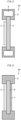
- Fig. 2 is a cross-sectional view illustrating a variation of the target in accordance with Embodiment 1.
- a target (B) which is Variation 1
- the target support frame 5 is a frame that supports at least the peripheral portion of the graphite film 4, and is preferably composed of a metal because the metal has excellent mechanical strength, excellent thermal conductivity, and excellent durability.
- the target (B) of Variation 1 is supported by the target support frame 5.
- This makes it possible to achieve a cartridge-type structure (cassette-type structure) that makes the target (B) easily attachable/detachable.
- the target support frame 5 is composed of a metal, heat generated in the target (B) can be easily guided through the target support frame 5 to a separately provided cooling mechanism.
- Fig. 3 is a cross-sectional view illustrating another variation of the target in accordance with Embodiment 1.
- a target (C) which is Variation 2
- a coolant for passage through the coolant flow channel 6 is a liquid with a high thermal conductivity such as cooling water, or a gas.
- the target support frame 5 since the target support frame 5 has the coolant flow channel 6 therein, heat generated in the target (C) is quickly cooled by the coolant flow channel 6 serving as a cooling mechanism provided in the target support frame 5. This improves the durability of the target (C) and also improves nuclear reaction efficiency.
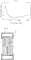
- the collision stopping power (energy loss) of a target material (in this case, the graphite film 4) for a charged particle (proton) is represented by the following Bethe equation (equation (3)):
- S col ⁇ 4 ⁇ ⁇ e 4 z 2 N mv 2 Z ln 2 mv 2 I 1 ⁇ ⁇ 2 ⁇ ⁇ 2
- e represents elementary charge of electron
- m represents mass of electron
- v velocity of electron
- z nuclear charge of incident particle
- Z represents the atomic number of the target material
- N represents the number of atoms per unit volume of the target material
- I represents the mean excitation potential of the target material
- ⁇ represents v/c where c is the speed of light.
- Fig. 5 is a graph showing the relationship between the stopping power based on the Bethe equation (equation (3)) and kinetic energy of particle.
- the collision stopping power (energy loss) of a target material for a charged particle increases from A (kinetic energy of particle is low) to B and reaches maximum at B.
- the stopping power decreases from B to C in proportion to I/v 2 , and reaches minimum at C.
- the stopping power gradually increases from C to D, where logarithms of the Bethe equation (equation (3)) are effective.
- the heat generation caused by irradiation with an accelerated proton beam is not reduced even when the energy of the accelerated proton beam is small, and therefore, even in the case of irradiation with a low-energy proton beam, the target is required to have high durability.
- a method of generating neutrons in accordance with Embodiment 1 involves generating low-energy neutrons with a reduced amount of fast neutrons that are harmful and that have the high ability to cause radioactivation, through collision of low-energy protons with a target in vacuum.
- the target used in Embodiment 1 is a substrate constituted by: a graphite film 4 having the foregoing properties; and a metal film 3 that is attached to one side of the graphite film 4 and that is equal to or greater than 10 ⁇ m and less than 1 mm in thickness.
- a surface of the metal film 3, that is, the surface located at a target's surface, is arranged so as to face the direction of travel of proton. This is in order to allow a nuclear reaction between proton and metal to take place first.
- Neutrons that can be generated by the method of generating neutrons in accordance with Embodiment 1 are low-energy neutrons including large amounts of thermal neutrons or epithermal neutrons.
- Low-energy neutrons refer to neutrons with a reduced amount of fast-neutrons that are harmful and that have the high ability to cause radioactivation.
- Fast neutrons are 100 times or more as high in energy as thermal neutrons or epithermal neutrons, and therefore are biologically harmful and have the very high ability to cause radioactivation.
- Neutron is categorized into fast neutron, epithermal neutron, thermal neutron, and cold neutron.
- epithermal neutron usually refers to neutron falling within the energy range of from 1 eV to 10 keV
- thermal neutron usually refers to neutron falling within the energy range of equal to and less than 0.5 eV.
- low-energy neutron refers to neutron with a reduced amount of fast neutron of 0.5 MeV or greater.
- the energy of incident proton is greater than 8 MeV
- neutron of 5 MeV or greater may be contained; however, the amount of such neutron can be reduced significantly as compared to conventional primary neutron.
- a neutron generator in accordance with Embodiment 1 includes a target, a hydrogen ion generator, a linear accelerator, and a proton emitting section.
- An accelerator for generating protons in a neutron generator is a linear accelerator.
- a large accelerator such as a synchrotron or a cyclotron is used in order to use, as proton for collision with a target, high-energy proton of 11 MeV or greater.
- mainly used proton is equal to or greater than 2 MeV and less than 11 MeV. Therefore, a linear accelerator is sufficient to generate desired large-current proton.
- the linear accelerator includes the hydrogen ion generator at one end thereof. Hydrogen ions from the hydrogen ion generator enter an acceleration cavity through a charged particle converting film and are accelerated.
- the hydrogen ion generator is not particularly limited, and can be, for example, a conventional proton generator, a conventional negative hydrogen ion generator, or the like.
- the acceleration cavity can be a radio frequency accelerating cavity, a DC acceleration cavity, a normal conducting accelerating cavity, a superconducting accelerating cavity, or the like.
- the proton beam emitting section is provided on the opposite side of the linear accelerator from the hydrogen ion generator.
- the proton beam emitting section is provided between the linear accelerator and the target.
- the proton emitting section is not particularly limited, and can be a conventional proton emitting section that includes a quadrupole electromagnet and a bending magnet.
- the protons accelerated by the linear accelerator are guided to the proton emitting section connected at an end of the linear accelerator, and collide with the target at an end of the proton emitting section. Through this collision, low-energy neutrons are generated.
- the targets (B) to (D) each include a metal film 3, a graphite film 4, and a target support frame 5 that has a cooling function.
- the neutron generator in accordance with Embodiment 1 may employ the following arrangement: a target (B), (C), or (D), which has a cartridge-type structure, is provided at an end of the proton emitting section with a vacuum flange therebetween which has a semiautomatic detach/attach structure. This makes it possible to easily replace a deteriorated target with a new target by detaching the deteriorated target and attaching the new target via remote control.
- a neutron generator in accordance with Embodiment 1 can also be installed in small-scale medical institutions as a medical neutron generator for generation of neutron for medical purposes such as BNCT.
- a substrate that supports a metal film 3 may be constituted by a graphite stack 8 as described in Embodiment 2.
- each of the graphite films 4 is equal to or greater than 1 ⁇ m and equal to or less than 100 ⁇ m.
- the graphite stack 8 can be prepared by uniting a plurality of graphite films 4 by heating the graphite films 4 under pressure or by uniting a plurality of graphite films 4 by pressing the graphite films 4 under heat. That is, the graphite stack 8 is a laminate of a plurality of graphite films 4 united together by means of pressure or heat. Since the substrate that supports the metal film 3 is constituted by the graphite stack 8 as described above, durability and heat resistance against proton beam irradiation improve.
- the thickness of the graphite stack 8, which serves as a target substrate, is equal to or greater than 100 ⁇ m and equal to or less than 20 mm, more preferably equal to or greater than 200 ⁇ m and equal to or less than 10 mm.
- the target (E) in accordance with Embodiment 2 also preferably has a target support frame 5 attached thereto as illustrated in Fig. 6 , depending on need.
- the target support frame 5 has a flow channel 6 serving as a cooling mechanism.
- stacking a plurality of graphite films 4 like Embodiment 2 is useful in a case where the energy of an accelerated proton beam is relatively high. If the energy of an accelerated proton beam is high and a target is too thin, the proton beam unintentionally passes through the target. This not only dramatically reduces neutron generation efficiency but also causes mixing of generated neutrons and a proton beam, and thus is not preferred. Furthermore, even in a case where the proton beam is shielded against, fast neutrons that are harmful in medical applications such as cancer therapy may be mixed in the generated neutrons if neutron generation is carried out using a high-energy proton beam.
- the target substrate in some cases serves also to decelerate such neutrons, and therefore a target for neutron generation is required to have a thickness that is suitable for the energy of a proton beam with which the target is irradiated and that is suitable for the intended purpose of generated neutrons.
- the graphite stack 8 is prepared by stacking together a plurality of graphite films 4 each having a thickness in the range of from 1 ⁇ m to 100 ⁇ m. Therefore, thermal conductivity or electric conductivity characteristics are basically not lost, and basically a target substrate of any thickness can be prepared. Embodiment 2 thus provides a very superior method.
- the conditions under which the graphite films 4 are pressed and/or heated are not limited, provided that the graphite films 4 constituting the resulting graphite stack 8 are sufficiently strongly united together, but the graphite films 4 are pressed and/or heated preferably in vacuum or in an inert gas such as argon or nitrogen under the conditions in which heating temperature is in the range of from 200°C to 3000°C and applied pressure is equal to or greater than 10 4 pascals. Heating while pressing or pressing while heating is particularly preferred as a method of preparing a laminate.
- the graphite films 4 constituting the graphite stack 8 do not necessarily have to be fully graphitized, and may be films carbonized at a temperature equal to or above 600°C, more preferably equal to or above 800°C, most preferably equal to or above 1000°C. By stacking such carbonized films and, for example, heating the films and/or pressing the films at a temperature equal to or above 2800°C, it is possible to obtain a desired target substrate.
- the present invention is not limited to the embodiments, but can be altered by a skilled person in the art within the scope of the claims.
- the present invention also encompasses, in its technical scope, any embodiment derived by combining technical means disclosed in differing embodiments. Further, it is possible to form a new technical feature by combining the technical means disclosed in the respective embodiments.
- the substrate is constituted by a graphite film.
- the graphite film has a thermal conductivity in a surface direction of 1500 W/(m ⁇ K) or greater, and the thermal conductivity in the surface direction of the graphite film is equal to or greater than 100 times a thermal conductivity in a thickness direction of the graphite film. This makes it possible to quickly transfer the heat generated by proton beam irradiation to a cooling section, and thus the substrate is sufficiently durable.
- the graphite film has a thickness of 1 ⁇ m or greater and 100 ⁇ m or less.
- a graphite film having such a thickness is mechanically strong enough to serve as a substrate that supports a metal film despite its very small thickness.
- the target in accordance with one embodiment of the present invention is preferably arranged such that: the graphite film has an electric conductivity in the surface direction of 16000 S/cm or greater; and the electric conductivity in the surface direction of the graphite film is equal to or greater than 100 times an electric conductivity in the thickness direction of the graphite film.
- the measurement of electric conductivity is very easy as compared to the measurement of thermal conductivity characteristics, and electric conductivity characteristics are well proportional to thermal conductivity characteristics. It is therefore possible to appropriately manage the performance of a graphite film as a substrate by measurement of electric conductivity characteristics.
- the target in accordance with one embodiment of the present invention is preferably arranged such that: the substrate is constituted by a graphite stack which is a plurality of the graphite films stacked together; and the substrate is equal to or greater than 100 ⁇ m and equal to or less than 20 mm in thickness.
- the substrate is constituted by a graphite stack which is a plurality of the graphite films stacked together. This makes it possible to obtain a thicker substrate without losing thermal conductivity characteristics.
- a substrate constituted by a plurality of graphite films is sufficiently durable despite its thickness smaller than conventional substrates composed of isotropic graphite. This improves durability and heat resistance against irradiation with relatively high-energy proton beams, and is capable of not only neutron generation using proton beams in the energy ranges currently used only in medical applications but also neutron generation using higher-energy proton beams.
- the target in accordance with one embodiment of the present invention is preferably arranged such that the graphite stack is a laminate obtained by uniting the plurality of graphite films by heating the plurality of graphite films under pressure or a laminate obtained by uniting the plurality of graphite films by pressing the plurality of graphite films under heat.
- the target in accordance with one embodiment of the present invention is preferably arranged such that the graphite film is equal to or greater than 1.60 g/cm 3 and equal to or less than 2.26 g/cm 3 in density.
- the target of an embodiment of the present invention is preferably structured such that the graphite film and the metal film are directly joined together.
- the target includes a metal film that is composed of a metal and that is stacked on the graphite film.
- metal film that is composed of a metal and that is stacked on the graphite film refers to a metal film directly joined to the graphite film.
- the target in accordance with one embodiment of the present invention preferably has a support frame that supports the target.
- the target has a support frame that supports the target. This improves the mechanical strength and durability of the target.
- the target in accordance with one embodiment of the present invention is preferably arranged such that the support frame includes a cooling mechanism for cooling the target.
- a neutron generator in accordance with one embodiment of the present invention includes: an accelerator configured to accelerate a proton; and a proton emitting section configured to emit, toward the foregoing target, the proton accelerated by the accelerator.
- a method of producing a target in accordance with one embodiment of the present invention is a method of producing a target that includes: a metal film composed of a beryllium material or a lithium material; and one or more graphite films composed of graphite, the target being configured to generate a neutron upon collision of a proton with a surface of the metal film and a surface of the graphite film, the method including a step of preparing the one or more graphite films by firing one or more polymeric films.
- the present invention can be used in, for example, a medical neutron generator for generation of neutron for medical purposes such as BNCT.
Landscapes
- Physics & Mathematics (AREA)
- High Energy & Nuclear Physics (AREA)
- Engineering & Computer Science (AREA)
- Spectroscopy & Molecular Physics (AREA)
- General Engineering & Computer Science (AREA)
- Chemical & Material Sciences (AREA)
- Chemical Kinetics & Catalysis (AREA)
- Plasma & Fusion (AREA)
- General Chemical & Material Sciences (AREA)
- Optics & Photonics (AREA)
- Particle Accelerators (AREA)
- Radiation-Therapy Devices (AREA)
Applications Claiming Priority (2)
| Application Number | Priority Date | Filing Date | Title |
|---|---|---|---|
| JP2016085302 | 2016-04-21 | ||
| PCT/JP2017/015906 WO2017183693A1 (ja) | 2016-04-21 | 2017-04-20 | ターゲット、ターゲットの製造方法、及び中性子発生装置 |
Publications (3)
| Publication Number | Publication Date |
|---|---|
| EP3447773A1 true EP3447773A1 (de) | 2019-02-27 |
| EP3447773A4 EP3447773A4 (de) | 2019-03-27 |
| EP3447773B1 EP3447773B1 (de) | 2021-06-09 |
Family
ID=60116133
Family Applications (1)
| Application Number | Title | Priority Date | Filing Date |
|---|---|---|---|
| EP17786030.1A Active EP3447773B1 (de) | 2016-04-21 | 2017-04-20 | Target, targetherstellungsverfahren und neutronenerzeugungsvorrichtung |
Country Status (5)
| Country | Link |
|---|---|
| US (1) | US20190122780A1 (de) |
| EP (1) | EP3447773B1 (de) |
| JP (1) | JPWO2017183693A1 (de) |
| CN (1) | CN109074890B (de) |
| WO (1) | WO2017183693A1 (de) |
Cited By (3)
| Publication number | Priority date | Publication date | Assignee | Title |
|---|---|---|---|---|
| EP3447774A4 (de) * | 2016-04-21 | 2019-05-08 | Kaneka Corporation | Trägersubstrat zur radioisotopherstellung, zielplatte zur radioisotopherstellung und herstellungsverfahren für trägersubstrat |
| DE102018007843B3 (de) * | 2018-10-01 | 2020-01-16 | Forschungszentrum Jülich GmbH | Verfahren zum Auffinden eines Targetmaterials und Targetmaterial für eine Neutronenquelle |
| US11177116B2 (en) | 2016-04-28 | 2021-11-16 | Kaneka Corporation | Beam intensity converting film, and method of manufacturing beam intensity converting film |
Families Citing this family (15)
| Publication number | Priority date | Publication date | Assignee | Title |
|---|---|---|---|---|
| JP7061899B2 (ja) * | 2018-03-07 | 2022-05-02 | 株式会社アルバック | リチウムターゲットの製造方法及び製造装置 |
| CN108550411B (zh) * | 2018-05-29 | 2024-08-16 | 河南太粒科技有限公司 | 一种镶嵌式靶结构 |
| KR102801596B1 (ko) | 2018-06-06 | 2025-04-30 | 피닉스 뉴트론 이미징 엘엘씨 | 중성자 생성을 위한 이온 빔 타겟 어셈블리 |
| US11430580B2 (en) * | 2018-07-09 | 2022-08-30 | Advanced Accelerator Applications | Neutron activator includes a metallic plate target configured to produce protons through interaction with a proton beam and method of use |
| JP7164161B2 (ja) * | 2018-08-02 | 2022-11-01 | 国立研究開発法人理化学研究所 | ターゲット構造、ターゲット装置、及びターゲット装置を備える装置 |
| WO2022212821A1 (en) * | 2021-04-02 | 2022-10-06 | Tae Technologies, Inc. | Materials and configurations for protection of objective materials |
| CN117413322B (zh) * | 2021-04-16 | 2025-09-30 | 极光基础设施埃里克 | 一种核靶、用于诱导核反应的方法以及适用于实施该方法的装置 |
| JP7827826B2 (ja) * | 2021-07-16 | 2026-03-10 | 中硼(厦▲門▼)医▲療▼器械有限公司 | 粒子ビーム発生装置に用いられるターゲット |
| CN218652758U (zh) * | 2022-01-13 | 2023-03-21 | 新华锦集团有限公司 | Bnct用锂靶 |
| JP7687569B2 (ja) * | 2022-03-23 | 2025-06-03 | 日本電信電話株式会社 | Seuクロスセクション推定装置及びseuクロスセクション推定方法並びにseuクロスセクション推定プログラム |
| WO2024054607A2 (en) * | 2022-09-09 | 2024-03-14 | The Regents Of The University Of California | Deuteron breakup neutron target for isotope production |
| US20240121879A1 (en) * | 2022-10-05 | 2024-04-11 | Tae Technologies, Inc. | Lithium target with intermediate layer |
| CN115499993B (zh) * | 2022-10-21 | 2024-02-20 | 国重医疗科技(重庆)有限公司 | 中子靶系统 |
| CN116913573B (zh) * | 2023-08-01 | 2024-01-23 | 烟台大学 | 一种中子聚束器 |
| CN118390012B (zh) * | 2024-06-27 | 2024-08-30 | 中国科学院近代物理研究所 | 一种以自支撑碳膜为衬底的镉靶及其制备方法 |
Family Cites Families (15)
| Publication number | Priority date | Publication date | Assignee | Title |
|---|---|---|---|---|
| JPH08222239A (ja) * | 1995-02-10 | 1996-08-30 | Tanaka Kikinzoku Kogyo Kk | 燃料電池用カーボンプレート及びその製造方法 |
| JPH09142820A (ja) * | 1995-11-21 | 1997-06-03 | Matsushita Electric Ind Co Ltd | 異方性黒鉛薄膜基板、並びにそれを用いた応用装置及び応用素子 |
| US5920601A (en) * | 1996-10-25 | 1999-07-06 | Lockheed Martin Idaho Technologies Company | System and method for delivery of neutron beams for medical therapy |
| JP3950389B2 (ja) * | 2002-08-14 | 2007-08-01 | 浜松ホトニクス株式会社 | X線管 |
| JP2006196353A (ja) | 2005-01-14 | 2006-07-27 | Hitachi Ltd | 加速器中性子源及びこれを用いたホウ素中性子捕捉療法システム |
| KR200478915Y1 (ko) * | 2010-09-21 | 2015-12-01 | 그라프텍 인터내셔널 홀딩스 인코포레이티드 | 복합물 열 스프레더 |
| JP5751673B2 (ja) * | 2011-09-02 | 2015-07-22 | 大学共同利用機関法人 高エネルギー加速器研究機構 | 複合型ターゲット、複合型ターゲットを用いる中性子発生方法、及び複合型ターゲットを用いる中性子発生装置 |
| JP2012243640A (ja) | 2011-05-20 | 2012-12-10 | High Energy Accelerator Research Organization | 複合型ターゲット、複合型ターゲットを用いる中性子発生方法、及び複合型ターゲットを用いる中性子発生装置 |
| JP5700536B2 (ja) | 2011-03-04 | 2015-04-15 | 大学共同利用機関法人 高エネルギー加速器研究機構 | 複合型ターゲット |
| JP5697021B2 (ja) | 2010-11-29 | 2015-04-08 | 大学共同利用機関法人 高エネルギー加速器研究機構 | 複合型ターゲット、複合型ターゲットを用いる中性子発生方法、及び複合型ターゲットを用いる中性子発生装置 |
| JP2013206726A (ja) | 2012-03-28 | 2013-10-07 | High Energy Accelerator Research Organization | 複合型ターゲット、複合型ターゲットを用いる中性子発生方法、及び複合型ターゲットを用いる中性子発生装置 |
| JP6218174B2 (ja) * | 2012-04-12 | 2017-10-25 | 大学共同利用機関法人 高エネルギー加速器研究機構 | 複合型ターゲット、複合型ターゲットを用いる中性子発生方法、及び複合型ターゲットを用いる中性子発生装置 |
| US20130280470A1 (en) * | 2012-04-20 | 2013-10-24 | Julian Norly | Thermal Management For Aircraft Composites |
| JP6113453B2 (ja) * | 2012-07-13 | 2017-04-12 | 株式会社八神製作所 | 中性子発生装置用のターゲットとその製造方法 |
| CN104561906B (zh) * | 2014-12-24 | 2017-03-08 | 武汉理工大学 | 一种梯度碳化硼薄膜及其制备方法 |
-
2017
- 2017-04-20 CN CN201780024720.3A patent/CN109074890B/zh active Active
- 2017-04-20 US US16/092,986 patent/US20190122780A1/en not_active Abandoned
- 2017-04-20 JP JP2018513212A patent/JPWO2017183693A1/ja active Pending
- 2017-04-20 WO PCT/JP2017/015906 patent/WO2017183693A1/ja not_active Ceased
- 2017-04-20 EP EP17786030.1A patent/EP3447773B1/de active Active
Cited By (4)
| Publication number | Priority date | Publication date | Assignee | Title |
|---|---|---|---|---|
| EP3447774A4 (de) * | 2016-04-21 | 2019-05-08 | Kaneka Corporation | Trägersubstrat zur radioisotopherstellung, zielplatte zur radioisotopherstellung und herstellungsverfahren für trägersubstrat |
| US11239003B2 (en) | 2016-04-21 | 2022-02-01 | Kaneka Corporation | Support substrate for radioisotope production, target plate for radioisotope production, and production method for support substrate |
| US11177116B2 (en) | 2016-04-28 | 2021-11-16 | Kaneka Corporation | Beam intensity converting film, and method of manufacturing beam intensity converting film |
| DE102018007843B3 (de) * | 2018-10-01 | 2020-01-16 | Forschungszentrum Jülich GmbH | Verfahren zum Auffinden eines Targetmaterials und Targetmaterial für eine Neutronenquelle |
Also Published As
| Publication number | Publication date |
|---|---|
| JPWO2017183693A1 (ja) | 2018-12-13 |
| US20190122780A1 (en) | 2019-04-25 |
| EP3447773B1 (de) | 2021-06-09 |
| CN109074890A (zh) | 2018-12-21 |
| EP3447773A4 (de) | 2019-03-27 |
| CN109074890B (zh) | 2023-07-04 |
| WO2017183693A1 (ja) | 2017-10-26 |
Similar Documents
| Publication | Publication Date | Title |
|---|---|---|
| EP3447773B1 (de) | Target, targetherstellungsverfahren und neutronenerzeugungsvorrichtung | |
| US11239003B2 (en) | Support substrate for radioisotope production, target plate for radioisotope production, and production method for support substrate | |
| JP5697021B2 (ja) | 複合型ターゲット、複合型ターゲットを用いる中性子発生方法、及び複合型ターゲットを用いる中性子発生装置 | |
| Halfon et al. | High-power liquid-lithium jet target for neutron production | |
| EP2648490A1 (de) | Kombiniertes target, neutronenerzeugungsverfahren unter verwendung des kombinierten targets und neutronenerzeugungsvorrichtung unter verwendung des kombinierten targets | |
| JP6218174B2 (ja) | 複合型ターゲット、複合型ターゲットを用いる中性子発生方法、及び複合型ターゲットを用いる中性子発生装置 | |
| JP2013206726A (ja) | 複合型ターゲット、複合型ターゲットを用いる中性子発生方法、及び複合型ターゲットを用いる中性子発生装置 | |
| JP5751673B2 (ja) | 複合型ターゲット、複合型ターゲットを用いる中性子発生方法、及び複合型ターゲットを用いる中性子発生装置 | |
| CN218652758U (zh) | Bnct用锂靶 | |
| US10420959B2 (en) | Energy degrader, charged particle beam emission system provided with same, and method of producing graphite film | |
| Yoshihashi et al. | High heat removal technique for a lithium neutron generation target used for an accelerator-driven BNCT system | |
| Storms | An explanation of low-energy nuclear reactions (cold fusion) | |
| JP5700536B2 (ja) | 複合型ターゲット | |
| US8227020B1 (en) | Dislocation site formation techniques | |
| US11177116B2 (en) | Beam intensity converting film, and method of manufacturing beam intensity converting film | |
| Torrisi et al. | Target normal sheath ion acceleration by fs laser irradiating metal/reduced graphene oxide targets | |
| Csikai et al. | Production of solid deuterium targets by ion implantation | |
| Mitchell et al. | DT fusion neutron radiation strengthening of copper and niobium | |
| Gardes | Basic Data for Materials Modifications and Analysis | |
| Lipson et al. | Evidence for condensed matter enhanced nuclear reactions in metals with a high hydrogen solubility | |
| Tian | Deuterium retention in polycrystalline tungsten | |
| FURUSAKA | 2. 5 Nuclear Data Needs from Non-energetic Fields (Material Science Research) | |
| Kaminsky | Considerations of test facility requirements for CTR surface science experiments | |
| Jaskola et al. | Impurities Level and the Life Time of the Plastic Foils Irradiated by the Charged Projectiles | |
| McCarthy | US DEPARTMENT OF ENERGY NUCLEAR ENGINEERING EDUCATION RESEARCH: HIGHLIGHTS OF RECENT AND CURRENT RESEARCH—III |
Legal Events
| Date | Code | Title | Description |
|---|---|---|---|
| STAA | Information on the status of an ep patent application or granted ep patent |
Free format text: STATUS: THE INTERNATIONAL PUBLICATION HAS BEEN MADE |
|
| PUAI | Public reference made under article 153(3) epc to a published international application that has entered the european phase |
Free format text: ORIGINAL CODE: 0009012 |
|
| STAA | Information on the status of an ep patent application or granted ep patent |
Free format text: STATUS: REQUEST FOR EXAMINATION WAS MADE |
|
| 17P | Request for examination filed |
Effective date: 20181107 |
|
| AK | Designated contracting states |
Kind code of ref document: A1 Designated state(s): AL AT BE BG CH CY CZ DE DK EE ES FI FR GB GR HR HU IE IS IT LI LT LU LV MC MK MT NL NO PL PT RO RS SE SI SK SM TR |
|
| AX | Request for extension of the european patent |
Extension state: BA ME |
|
| A4 | Supplementary search report drawn up and despatched |
Effective date: 20190225 |
|
| RIC1 | Information provided on ipc code assigned before grant |
Ipc: G21G 4/02 20060101ALI20190219BHEP Ipc: H05H 3/06 20060101ALI20190219BHEP Ipc: G21K 5/08 20060101AFI20190219BHEP Ipc: H05H 6/00 20060101ALI20190219BHEP |
|
| DAV | Request for validation of the european patent (deleted) | ||
| DAX | Request for extension of the european patent (deleted) | ||
| GRAP | Despatch of communication of intention to grant a patent |
Free format text: ORIGINAL CODE: EPIDOSNIGR1 |
|
| STAA | Information on the status of an ep patent application or granted ep patent |
Free format text: STATUS: GRANT OF PATENT IS INTENDED |
|
| INTG | Intention to grant announced |
Effective date: 20200922 |
|
| GRAJ | Information related to disapproval of communication of intention to grant by the applicant or resumption of examination proceedings by the epo deleted |
Free format text: ORIGINAL CODE: EPIDOSDIGR1 |
|
| STAA | Information on the status of an ep patent application or granted ep patent |
Free format text: STATUS: REQUEST FOR EXAMINATION WAS MADE |
|
| INTC | Intention to grant announced (deleted) | ||
| GRAP | Despatch of communication of intention to grant a patent |
Free format text: ORIGINAL CODE: EPIDOSNIGR1 |
|
| STAA | Information on the status of an ep patent application or granted ep patent |
Free format text: STATUS: GRANT OF PATENT IS INTENDED |
|
| INTG | Intention to grant announced |
Effective date: 20210126 |
|
| GRAS | Grant fee paid |
Free format text: ORIGINAL CODE: EPIDOSNIGR3 |
|
| GRAA | (expected) grant |
Free format text: ORIGINAL CODE: 0009210 |
|
| STAA | Information on the status of an ep patent application or granted ep patent |
Free format text: STATUS: THE PATENT HAS BEEN GRANTED |
|
| AK | Designated contracting states |
Kind code of ref document: B1 Designated state(s): AL AT BE BG CH CY CZ DE DK EE ES FI FR GB GR HR HU IE IS IT LI LT LU LV MC MK MT NL NO PL PT RO RS SE SI SK SM TR |
|
| REG | Reference to a national code |
Ref country code: GB Ref legal event code: FG4D |
|
| REG | Reference to a national code |
Ref country code: CH Ref legal event code: EP Ref country code: AT Ref legal event code: REF Ref document number: 1401161 Country of ref document: AT Kind code of ref document: T Effective date: 20210615 |
|
| REG | Reference to a national code |
Ref country code: DE Ref legal event code: R096 Ref document number: 602017040069 Country of ref document: DE |
|
| REG | Reference to a national code |
Ref country code: IE Ref legal event code: FG4D |
|
| REG | Reference to a national code |
Ref country code: LT Ref legal event code: MG9D |
|
| PG25 | Lapsed in a contracting state [announced via postgrant information from national office to epo] |
Ref country code: FI Free format text: LAPSE BECAUSE OF FAILURE TO SUBMIT A TRANSLATION OF THE DESCRIPTION OR TO PAY THE FEE WITHIN THE PRESCRIBED TIME-LIMIT Effective date: 20210609 Ref country code: LT Free format text: LAPSE BECAUSE OF FAILURE TO SUBMIT A TRANSLATION OF THE DESCRIPTION OR TO PAY THE FEE WITHIN THE PRESCRIBED TIME-LIMIT Effective date: 20210609 Ref country code: HR Free format text: LAPSE BECAUSE OF FAILURE TO SUBMIT A TRANSLATION OF THE DESCRIPTION OR TO PAY THE FEE WITHIN THE PRESCRIBED TIME-LIMIT Effective date: 20210609 Ref country code: BG Free format text: LAPSE BECAUSE OF FAILURE TO SUBMIT A TRANSLATION OF THE DESCRIPTION OR TO PAY THE FEE WITHIN THE PRESCRIBED TIME-LIMIT Effective date: 20210909 |
|
| REG | Reference to a national code |
Ref country code: AT Ref legal event code: MK05 Ref document number: 1401161 Country of ref document: AT Kind code of ref document: T Effective date: 20210609 |
|
| REG | Reference to a national code |
Ref country code: NL Ref legal event code: MP Effective date: 20210609 |
|
| PG25 | Lapsed in a contracting state [announced via postgrant information from national office to epo] |
Ref country code: GR Free format text: LAPSE BECAUSE OF FAILURE TO SUBMIT A TRANSLATION OF THE DESCRIPTION OR TO PAY THE FEE WITHIN THE PRESCRIBED TIME-LIMIT Effective date: 20210910 Ref country code: RS Free format text: LAPSE BECAUSE OF FAILURE TO SUBMIT A TRANSLATION OF THE DESCRIPTION OR TO PAY THE FEE WITHIN THE PRESCRIBED TIME-LIMIT Effective date: 20210609 Ref country code: SE Free format text: LAPSE BECAUSE OF FAILURE TO SUBMIT A TRANSLATION OF THE DESCRIPTION OR TO PAY THE FEE WITHIN THE PRESCRIBED TIME-LIMIT Effective date: 20210609 Ref country code: LV Free format text: LAPSE BECAUSE OF FAILURE TO SUBMIT A TRANSLATION OF THE DESCRIPTION OR TO PAY THE FEE WITHIN THE PRESCRIBED TIME-LIMIT Effective date: 20210609 Ref country code: NO Free format text: LAPSE BECAUSE OF FAILURE TO SUBMIT A TRANSLATION OF THE DESCRIPTION OR TO PAY THE FEE WITHIN THE PRESCRIBED TIME-LIMIT Effective date: 20210909 |
|
| PG25 | Lapsed in a contracting state [announced via postgrant information from national office to epo] |
Ref country code: SK Free format text: LAPSE BECAUSE OF FAILURE TO SUBMIT A TRANSLATION OF THE DESCRIPTION OR TO PAY THE FEE WITHIN THE PRESCRIBED TIME-LIMIT Effective date: 20210609 Ref country code: SM Free format text: LAPSE BECAUSE OF FAILURE TO SUBMIT A TRANSLATION OF THE DESCRIPTION OR TO PAY THE FEE WITHIN THE PRESCRIBED TIME-LIMIT Effective date: 20210609 Ref country code: NL Free format text: LAPSE BECAUSE OF FAILURE TO SUBMIT A TRANSLATION OF THE DESCRIPTION OR TO PAY THE FEE WITHIN THE PRESCRIBED TIME-LIMIT Effective date: 20210609 Ref country code: PT Free format text: LAPSE BECAUSE OF FAILURE TO SUBMIT A TRANSLATION OF THE DESCRIPTION OR TO PAY THE FEE WITHIN THE PRESCRIBED TIME-LIMIT Effective date: 20211011 Ref country code: RO Free format text: LAPSE BECAUSE OF FAILURE TO SUBMIT A TRANSLATION OF THE DESCRIPTION OR TO PAY THE FEE WITHIN THE PRESCRIBED TIME-LIMIT Effective date: 20210609 Ref country code: ES Free format text: LAPSE BECAUSE OF FAILURE TO SUBMIT A TRANSLATION OF THE DESCRIPTION OR TO PAY THE FEE WITHIN THE PRESCRIBED TIME-LIMIT Effective date: 20210609 Ref country code: AT Free format text: LAPSE BECAUSE OF FAILURE TO SUBMIT A TRANSLATION OF THE DESCRIPTION OR TO PAY THE FEE WITHIN THE PRESCRIBED TIME-LIMIT Effective date: 20210609 Ref country code: CZ Free format text: LAPSE BECAUSE OF FAILURE TO SUBMIT A TRANSLATION OF THE DESCRIPTION OR TO PAY THE FEE WITHIN THE PRESCRIBED TIME-LIMIT Effective date: 20210609 Ref country code: EE Free format text: LAPSE BECAUSE OF FAILURE TO SUBMIT A TRANSLATION OF THE DESCRIPTION OR TO PAY THE FEE WITHIN THE PRESCRIBED TIME-LIMIT Effective date: 20210609 |
|
| PG25 | Lapsed in a contracting state [announced via postgrant information from national office to epo] |
Ref country code: PL Free format text: LAPSE BECAUSE OF FAILURE TO SUBMIT A TRANSLATION OF THE DESCRIPTION OR TO PAY THE FEE WITHIN THE PRESCRIBED TIME-LIMIT Effective date: 20210609 |
|
| REG | Reference to a national code |
Ref country code: DE Ref legal event code: R097 Ref document number: 602017040069 Country of ref document: DE |
|
| PLBE | No opposition filed within time limit |
Free format text: ORIGINAL CODE: 0009261 |
|
| STAA | Information on the status of an ep patent application or granted ep patent |
Free format text: STATUS: NO OPPOSITION FILED WITHIN TIME LIMIT |
|
| PG25 | Lapsed in a contracting state [announced via postgrant information from national office to epo] |
Ref country code: DK Free format text: LAPSE BECAUSE OF FAILURE TO SUBMIT A TRANSLATION OF THE DESCRIPTION OR TO PAY THE FEE WITHIN THE PRESCRIBED TIME-LIMIT Effective date: 20210609 |
|
| 26N | No opposition filed |
Effective date: 20220310 |
|
| PG25 | Lapsed in a contracting state [announced via postgrant information from national office to epo] |
Ref country code: AL Free format text: LAPSE BECAUSE OF FAILURE TO SUBMIT A TRANSLATION OF THE DESCRIPTION OR TO PAY THE FEE WITHIN THE PRESCRIBED TIME-LIMIT Effective date: 20210609 |
|
| PG25 | Lapsed in a contracting state [announced via postgrant information from national office to epo] |
Ref country code: IT Free format text: LAPSE BECAUSE OF FAILURE TO SUBMIT A TRANSLATION OF THE DESCRIPTION OR TO PAY THE FEE WITHIN THE PRESCRIBED TIME-LIMIT Effective date: 20210609 |
|
| GBPC | Gb: european patent ceased through non-payment of renewal fee |
Effective date: 20220420 |
|
| REG | Reference to a national code |
Ref country code: BE Ref legal event code: MM Effective date: 20220430 |
|
| PG25 | Lapsed in a contracting state [announced via postgrant information from national office to epo] |
Ref country code: MC Free format text: LAPSE BECAUSE OF FAILURE TO SUBMIT A TRANSLATION OF THE DESCRIPTION OR TO PAY THE FEE WITHIN THE PRESCRIBED TIME-LIMIT Effective date: 20210609 Ref country code: LU Free format text: LAPSE BECAUSE OF NON-PAYMENT OF DUE FEES Effective date: 20220420 Ref country code: GB Free format text: LAPSE BECAUSE OF NON-PAYMENT OF DUE FEES Effective date: 20220420 Ref country code: FR Free format text: LAPSE BECAUSE OF NON-PAYMENT OF DUE FEES Effective date: 20220430 |
|
| PG25 | Lapsed in a contracting state [announced via postgrant information from national office to epo] |
Ref country code: BE Free format text: LAPSE BECAUSE OF NON-PAYMENT OF DUE FEES Effective date: 20220430 |
|
| PG25 | Lapsed in a contracting state [announced via postgrant information from national office to epo] |
Ref country code: IE Free format text: LAPSE BECAUSE OF NON-PAYMENT OF DUE FEES Effective date: 20220420 |
|
| PG25 | Lapsed in a contracting state [announced via postgrant information from national office to epo] |
Ref country code: HU Free format text: LAPSE BECAUSE OF FAILURE TO SUBMIT A TRANSLATION OF THE DESCRIPTION OR TO PAY THE FEE WITHIN THE PRESCRIBED TIME-LIMIT; INVALID AB INITIO Effective date: 20170420 |
|
| PG25 | Lapsed in a contracting state [announced via postgrant information from national office to epo] |
Ref country code: MK Free format text: LAPSE BECAUSE OF FAILURE TO SUBMIT A TRANSLATION OF THE DESCRIPTION OR TO PAY THE FEE WITHIN THE PRESCRIBED TIME-LIMIT Effective date: 20210609 Ref country code: CY Free format text: LAPSE BECAUSE OF FAILURE TO SUBMIT A TRANSLATION OF THE DESCRIPTION OR TO PAY THE FEE WITHIN THE PRESCRIBED TIME-LIMIT Effective date: 20210609 |
|
| PG25 | Lapsed in a contracting state [announced via postgrant information from national office to epo] |
Ref country code: TR Free format text: LAPSE BECAUSE OF FAILURE TO SUBMIT A TRANSLATION OF THE DESCRIPTION OR TO PAY THE FEE WITHIN THE PRESCRIBED TIME-LIMIT Effective date: 20210609 |
|
| PG25 | Lapsed in a contracting state [announced via postgrant information from national office to epo] |
Ref country code: MT Free format text: LAPSE BECAUSE OF FAILURE TO SUBMIT A TRANSLATION OF THE DESCRIPTION OR TO PAY THE FEE WITHIN THE PRESCRIBED TIME-LIMIT Effective date: 20210609 |
|
| PGFP | Annual fee paid to national office [announced via postgrant information from national office to epo] |
Ref country code: DE Payment date: 20250305 Year of fee payment: 9 |
|
| PGFP | Annual fee paid to national office [announced via postgrant information from national office to epo] |
Ref country code: CH Payment date: 20250501 Year of fee payment: 9 |