EP3447946B1 - Wiederübertragungsparameterbestimmung - Google Patents
Wiederübertragungsparameterbestimmung Download PDFInfo
- Publication number
- EP3447946B1 EP3447946B1 EP18155727.3A EP18155727A EP3447946B1 EP 3447946 B1 EP3447946 B1 EP 3447946B1 EP 18155727 A EP18155727 A EP 18155727A EP 3447946 B1 EP3447946 B1 EP 3447946B1
- Authority
- EP
- European Patent Office
- Prior art keywords
- wireless communication
- communication device
- transmission
- data length
- retransmission
- Prior art date
- Legal status (The legal status is an assumption and is not a legal conclusion. Google has not performed a legal analysis and makes no representation as to the accuracy of the status listed.)
- Active
Links
Images


Classifications
-
- H—ELECTRICITY
- H04—ELECTRIC COMMUNICATION TECHNIQUE
- H04L—TRANSMISSION OF DIGITAL INFORMATION, e.g. TELEGRAPHIC COMMUNICATION
- H04L1/00—Arrangements for detecting or preventing errors in the information received
- H04L1/0001—Systems modifying transmission characteristics according to link quality, e.g. power backoff
- H04L1/0015—Systems modifying transmission characteristics according to link quality, e.g. power backoff characterised by the adaptation strategy
- H04L1/0017—Systems modifying transmission characteristics according to link quality, e.g. power backoff characterised by the adaptation strategy where the mode-switching is based on Quality of Service requirement
- H04L1/0018—Systems modifying transmission characteristics according to link quality, e.g. power backoff characterised by the adaptation strategy where the mode-switching is based on Quality of Service requirement based on latency requirement
-
- H—ELECTRICITY
- H04—ELECTRIC COMMUNICATION TECHNIQUE
- H04L—TRANSMISSION OF DIGITAL INFORMATION, e.g. TELEGRAPHIC COMMUNICATION
- H04L1/00—Arrangements for detecting or preventing errors in the information received
- H04L1/004—Arrangements for detecting or preventing errors in the information received by using forward error control
- H04L1/0056—Systems characterized by the type of code used
- H04L1/0061—Error detection codes
-
- H—ELECTRICITY
- H04—ELECTRIC COMMUNICATION TECHNIQUE
- H04L—TRANSMISSION OF DIGITAL INFORMATION, e.g. TELEGRAPHIC COMMUNICATION
- H04L1/00—Arrangements for detecting or preventing errors in the information received
- H04L1/004—Arrangements for detecting or preventing errors in the information received by using forward error control
- H04L1/0045—Arrangements at the receiver end
- H04L1/0047—Decoding adapted to other signal detection operation
- H04L1/005—Iterative decoding, including iteration between signal detection and decoding operation
-
- H—ELECTRICITY
- H04—ELECTRIC COMMUNICATION TECHNIQUE
- H04L—TRANSMISSION OF DIGITAL INFORMATION, e.g. TELEGRAPHIC COMMUNICATION
- H04L1/00—Arrangements for detecting or preventing errors in the information received
- H04L1/004—Arrangements for detecting or preventing errors in the information received by using forward error control
- H04L1/0072—Error control for data other than payload data, e.g. control data
-
- H—ELECTRICITY
- H04—ELECTRIC COMMUNICATION TECHNIQUE
- H04L—TRANSMISSION OF DIGITAL INFORMATION, e.g. TELEGRAPHIC COMMUNICATION
- H04L1/00—Arrangements for detecting or preventing errors in the information received
- H04L1/12—Arrangements for detecting or preventing errors in the information received by using return channel
- H04L1/16—Arrangements for detecting or preventing errors in the information received by using return channel in which the return channel carries supervisory signals, e.g. repetition request signals
- H04L1/1607—Details of the supervisory signal
- H04L1/1671—Details of the supervisory signal the supervisory signal being transmitted together with control information
-
- H—ELECTRICITY
- H04—ELECTRIC COMMUNICATION TECHNIQUE
- H04L—TRANSMISSION OF DIGITAL INFORMATION, e.g. TELEGRAPHIC COMMUNICATION
- H04L1/00—Arrangements for detecting or preventing errors in the information received
- H04L1/12—Arrangements for detecting or preventing errors in the information received by using return channel
- H04L1/16—Arrangements for detecting or preventing errors in the information received by using return channel in which the return channel carries supervisory signals, e.g. repetition request signals
- H04L1/18—Automatic repetition systems, e.g. Van Duuren systems
- H04L1/1812—Hybrid protocols; Hybrid automatic repeat request [HARQ]
- H04L1/1819—Hybrid protocols; Hybrid automatic repeat request [HARQ] with retransmission of additional or different redundancy
-
- H—ELECTRICITY
- H04—ELECTRIC COMMUNICATION TECHNIQUE
- H04L—TRANSMISSION OF DIGITAL INFORMATION, e.g. TELEGRAPHIC COMMUNICATION
- H04L1/00—Arrangements for detecting or preventing errors in the information received
- H04L1/12—Arrangements for detecting or preventing errors in the information received by using return channel
- H04L1/16—Arrangements for detecting or preventing errors in the information received by using return channel in which the return channel carries supervisory signals, e.g. repetition request signals
- H04L1/18—Automatic repetition systems, e.g. Van Duuren systems
- H04L1/1825—Adaptation of specific ARQ protocol parameters according to transmission conditions
-
- H—ELECTRICITY
- H04—ELECTRIC COMMUNICATION TECHNIQUE
- H04L—TRANSMISSION OF DIGITAL INFORMATION, e.g. TELEGRAPHIC COMMUNICATION
- H04L1/00—Arrangements for detecting or preventing errors in the information received
- H04L1/12—Arrangements for detecting or preventing errors in the information received by using return channel
- H04L1/16—Arrangements for detecting or preventing errors in the information received by using return channel in which the return channel carries supervisory signals, e.g. repetition request signals
- H04L1/18—Automatic repetition systems, e.g. Van Duuren systems
- H04L1/1829—Arrangements specially adapted for the receiver end
-
- H—ELECTRICITY
- H04—ELECTRIC COMMUNICATION TECHNIQUE
- H04W—WIRELESS COMMUNICATION NETWORKS
- H04W74/00—Wireless channel access
- H04W74/08—Non-scheduled access, e.g. ALOHA
- H04W74/0808—Non-scheduled access, e.g. ALOHA using carrier sensing, e.g. carrier sense multiple access [CSMA]
- H04W74/0816—Non-scheduled access, e.g. ALOHA using carrier sensing, e.g. carrier sense multiple access [CSMA] with collision avoidance
-
- H—ELECTRICITY
- H01—ELECTRIC ELEMENTS
- H01Q—ANTENNAS, i.e. RADIO AERIALS
- H01Q5/00—Arrangements for simultaneous operation of antennas on two or more different wavebands, e.g. dual-band or multi-band arrangements
-
- H—ELECTRICITY
- H04—ELECTRIC COMMUNICATION TECHNIQUE
- H04L—TRANSMISSION OF DIGITAL INFORMATION, e.g. TELEGRAPHIC COMMUNICATION
- H04L1/00—Arrangements for detecting or preventing errors in the information received
- H04L1/0001—Systems modifying transmission characteristics according to link quality, e.g. power backoff
- H04L1/0002—Systems modifying transmission characteristics according to link quality, e.g. power backoff by adapting the transmission rate
- H04L1/0003—Systems modifying transmission characteristics according to link quality, e.g. power backoff by adapting the transmission rate by switching between different modulation schemes
-
- H—ELECTRICITY
- H04—ELECTRIC COMMUNICATION TECHNIQUE
- H04L—TRANSMISSION OF DIGITAL INFORMATION, e.g. TELEGRAPHIC COMMUNICATION
- H04L1/00—Arrangements for detecting or preventing errors in the information received
- H04L1/0001—Systems modifying transmission characteristics according to link quality, e.g. power backoff
- H04L1/0009—Systems modifying transmission characteristics according to link quality, e.g. power backoff by adapting the channel coding
-
- H—ELECTRICITY
- H04—ELECTRIC COMMUNICATION TECHNIQUE
- H04L—TRANSMISSION OF DIGITAL INFORMATION, e.g. TELEGRAPHIC COMMUNICATION
- H04L1/00—Arrangements for detecting or preventing errors in the information received
- H04L1/0001—Systems modifying transmission characteristics according to link quality, e.g. power backoff
- H04L1/0015—Systems modifying transmission characteristics according to link quality, e.g. power backoff characterised by the adaptation strategy
- H04L1/0019—Systems modifying transmission characteristics according to link quality, e.g. power backoff characterised by the adaptation strategy in which mode-switching is based on a statistical approach
-
- H—ELECTRICITY
- H04—ELECTRIC COMMUNICATION TECHNIQUE
- H04L—TRANSMISSION OF DIGITAL INFORMATION, e.g. TELEGRAPHIC COMMUNICATION
- H04L1/00—Arrangements for detecting or preventing errors in the information received
- H04L1/0001—Systems modifying transmission characteristics according to link quality, e.g. power backoff
- H04L1/0023—Systems modifying transmission characteristics according to link quality, e.g. power backoff characterised by the signalling
- H04L1/0025—Transmission of mode-switching indication
-
- H—ELECTRICITY
- H04—ELECTRIC COMMUNICATION TECHNIQUE
- H04L—TRANSMISSION OF DIGITAL INFORMATION, e.g. TELEGRAPHIC COMMUNICATION
- H04L1/00—Arrangements for detecting or preventing errors in the information received
- H04L1/004—Arrangements for detecting or preventing errors in the information received by using forward error control
- H04L1/0075—Transmission of coding parameters to receiver
-
- H—ELECTRICITY
- H04—ELECTRIC COMMUNICATION TECHNIQUE
- H04L—TRANSMISSION OF DIGITAL INFORMATION, e.g. TELEGRAPHIC COMMUNICATION
- H04L1/00—Arrangements for detecting or preventing errors in the information received
- H04L1/0078—Avoidance of errors by organising the transmitted data in a format specifically designed to deal with errors, e.g. location
- H04L1/0083—Formatting with frames or packets; Protocol or part of protocol for error control
Definitions
- the embodiments discussed herein are related to a device for determining retransmission parameters in a wireless communication system.
- a wireless local area network (wireless LAN) has become widespread as a wireless communication system.
- Carrier sense multiple access collision avoidance (CSMA/CA) is often used in a wireless LAN.
- a transmission terminal checks whether a wireless resource is being used by other terminals before the transmission terminal starts transmitting data. When the wireless resource is not being used by other terminals, the transmission terminal transmits a data signal. This procedure permits an avoidance of a packet collision. However, a packet collision may occur when a plurality of terminals start transmitting data at the same time or when there exists a hidden terminal. When a packet collision has occurred, a reception terminal is not successful in receiving data.
- a retransmission control is performed between the transmission terminal and the reception terminal.
- the retransmission control is performed by, for example, a hybrid automatic repeat request (HARQ).
- HARQ hybrid automatic repeat request
- the HARQ can perform a retransmission control with incremental redundancy.
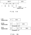
- a portion of encoded bits are transmitted in a first transmission, as illustrated in FIG. 1A .
- the encoded bits include data and a parity bit.
- the parity bit is redundancy information used to decode the data.
- Data and a portion of the parity bit are transmitted in the first transmission.
- data and a parity bit P1 are transmitted in the first transmission.
- the reception terminal tries to decode data using received bits.
- the reception terminal tries to decode the data using the parity bit P1.
- retransmission is not performed.
- retransmission is performed.
- a parity bit that has not been transmitted yet is transmitted in a retransmission scheme (that is, in the second and subsequent transmissions).
- the parity bit transmitted in the second and subsequent transmission may hereinafter be referred to as a "redundancy bit".
- a parity bit P2 illustrated in FIG. 1A is transmitted as a redundancy bit.
- the reception terminal tries to decode the data using previously received bits and a newly received redundancy bit.
- the reception terminal tries to decode the data using the parity bits P1 and P2, as illustrated in FIG. 1B .
- a retransmission control is performed repeatedly until data is decoded properly.
- parity bits P3, P4, ... are sequentially transmitted as a redundancy bit.
- a technology that applies HARQ to a wireless LAN protocol is disclosed in, for example, Japanese Patent No. 5254369 . Further, a retransmission control with incremental redundancy is disclosed in, for example, J. F. Cheng et al., "Adaptive Incremental Redundancy," IEEE 58th Veh. Technol. Conf. (VTC 2003-Fall), vol.2, pp.737-741, Oct. 2003 .
- the source terminal is not always able to immediately obtain a right to transmission during a next time period (contention window: CW) in which a right to transmission is to be obtained, so there is a possibility that a transmission efficiency (throughput) will be decreased because it may take a long time to perform a retransmission control.
- CW contention window
- An object according to an aspect of the present invention is to improve an efficiency in a retransmission control with incremental redundancy used in a wireless communication system.
- FIG. 2 illustrates an example of a wireless communication system according to embodiments of the present invention.
- a wireless communication system 1 illustrated in FIG. 2 is, for example, a wireless LAN system, although it is not particularly limited to this configuration.
- the wireless communication system 1 includes wireless communication devices 2 and 3.
- Each of the wireless communication devices 2 and 3 is, for example, a user equipment.
- the user equipment may be a mobile device.
- CSMA/CA is used in the wireless communication system 1 in order to avoid a packet collision. Note that a retransmission control with incremental redundancy is performed in this wireless LAN.
- the wireless communication device 2, 3 can transmit data using a plurality of frequency bands. Specifically, the wireless communication device 2, 3 can transmit data using a plurality of frequency bands at the same time. In the embodiments, the wireless communication device 2, 3 can transmit data using two or more frequency bands from among a 920MHz band, a 2.4GHz band, and a 5GHz band at the same time. The communication quality between the wireless communication devices 2 and 3 differs depending on the frequency band. Thus, the wireless communication device 2, 3 may transmit data using a different modulation scheme and a different code depending on the frequency band.
- data is transmitted using one frequency band.
- data is transmitted between the wireless communication devices 2 and 3 using one of the 920MHz band, the 2.4GHz band, and the 5GHz band.
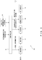
- FIG. 3 illustrates an example of a transmitter implemented in the wireless communication device.
- a transmitter 10 includes an encoder 11, a buffer 12, a reader 13, a modulator 14, a controller 15, and an RF circuit 16.
- the transmitter 10 may include other circuit elements that are not illustrated in FIG. 3 .
- the transmitter 10 may include a quality information storage 28 that will be described later.
- the encoder 11 encodes input data so as to generate encoded bits according to an instruction given by the controller 15.
- the controller 15 gives the encoder 11 an instruction that includes code information indicating a code type and/or a coding rate.
- the encoder 11 encodes input data so as to generate encoded bits using a code type and/or a coding rate that are specified by the controller 15.
- encoded bits include data and a parity bit.
- the encoded bits generated by the encoder 11 are stored in the buffer 12.
- the reader 13 reads a portion of the encoded bits stored in the buffer 12 according to an instruction given by the controller 15.
- the reader 13 reads the data and a portion of the parity bit (that is, the parity bit P1) from the buffer 12, as illustrated in FIG. 1A .
- the reader 13 reads a portion of the parity bit (that is, a redundancy bit) from the buffer 12.
- the length of a redundancy bit is specified by a retransmission parameter (in this case, a transmission data length).
- the modulator 14 modulates the bits read by the reader 13 so as to generate a modulated signal according to an instruction given by the controller 15.
- the controller 15 specifies a modulation scheme.
- the modulation scheme is specified by a user in advance.
- the modulation scheme may be dynamically determined according to the wireless environment.
- the controller 15 controls an operation of the transmitter 10.
- the controller 15 can control operations of the encoder 11, the reader 13, and the modulator 14.
- the controller 15 gives the encoder 11 an instruction indicating code information (a code type and/or a coding rate) .
- the controller 15 gives the modulator 14 an instruction indicating a modulation scheme.
- the controller 15 gives the reader 13 an instruction indicating a transmission data length.
- the controller 15 is implemented by, for example, a processor system that includes a processor element and a memory. In this case, the processor element provides the function of the controller 15 by executing a program stored in the memory. Alternatively, the controller 15 may be implemented by a digital signal processing circuit.
- the RF circuit 16 upconverts a modulated signal output from the modulator 14 to a radio frequency band (RF band), so as to generate an RF modulated signal.
- This RF modulated signal is output via an antenna.
- FIG. 4 illustrates an example of a receiver implemented in the wireless communication device.
- a receiver 20 includes a down-conversion circuit 21, a demodulator 22, a decoder 23, a buffer 24, a controller 25, and a quality information storage 28.
- the receiver 20 may include other circuit elements that are not illustrated in FIG. 4 .
- An RF modulated signal output from the transmitter 10 illustrated in FIG. 3 arrives at the receiver 20.
- the down-conversion circuit 21 downconverts the RF modulated signal received via an antenna to a baseband.
- the demodulator 22 demodulates an output signal of the down-conversion circuit 21 according to an instruction given by the controller 25.
- the demodulation process performed by the demodulator 22 corresponds to the modulation process performed by the modulator 14 in FIG. 3 .
- the decoder 23 decodes a demodulated signal output from the demodulator 22 according to an instruction given by the controller 25. In other words, the decoder 23 recovers the transmitted bits.
- the controller 25 specifies the number of iterations of an iterative decoding. Then, the decoder 23 performs decoding process repeatedly the number of times specified by the controller 25. When the decoder 23 is not successful in decoding received data, the decoder 23 reports the failure to the controller 25.
- the buffer 24 stores a demodulated signal output from the demodulator 22.
- the decoder 23 performs decoding process on the demodulated signal stored in the buffer 24 and a demodulated signal newly output from the demodulator 22 (that is, a likelihood value corresponding to redundancy bits) .
- a demodulated signal newly output from the demodulator 22 that is, a likelihood value corresponding to redundancy bits
- the decoder 23 performs decoding process on likelihood values corresponding to the data and the parity bit P1.
- the likelihood values corresponding to the data and the parity bit P1 of FIG. 1A or 1B are stored in the buffer 24.
- the parity bit P2 illustrated in FIG. 1A or 1B is transmitted as a redundancy bit.
- the decoder 23 performs decoding process on likelihood values corresponding to the data, the parity bit P1, and the parity bit P2. Likewise, a parity bit is added every time data retransmission is performed, which increases the chance that data will be properly decoded.
- the controller 25 controls an operation of the receiver 20.
- the controller 25 can control operations of the demodulator 22 and the decoder 23.
- the controller 25 includes an SNR estimator 26 and a retransmission controller 27.
- the controller 25 is implemented by, for example, a processor system that includes a processor element and a memory.
- the processor element provides the function of the controller 25 by executing a program stored in the memory.
- the controller 25 may be implemented by a digital signal processing circuit.
- the SNR estimator 26 estimates a signal-to-noise ratio (SNR) of a signal received from the transmitter 10 illustrated in FIG. 3 .
- the SNR is estimated by measuring a power in a specified region in a preamble of the received signal.
- the retransmission controller 27 includes a selector 27a, a transmission data length calculator 27b, a transmission latency calculator 27c, and a retransmission parameter generator 27d.
- the retransmission controller 27 generates a retransmission parameter when the decoder 23 is not successful in decoding received data.
- the selector 27a selects a communication pattern that satisfies a requested quality according to the SNR estimated by the SNR estimator 26.
- the communication pattern indicates a combination of a plurality of parameters including a coding rate and the number of iterations of an iterative decoding.
- the communication pattern may indicate a combination of a modulation scheme, a coding rate, and the number of iterations of an iterative decoding.
- the selector 27a may refer to quality information stored in the quality information storage 28 so as to select one or more communication patterns.
- the quality information indicates, for example, an error rate (for example, a block error rate: BLER) with respect to an SNR.
- the quality information is generated by measurement or simulation in advance and stored in the quality information storage 28.
- the transmission data length calculator 27b calculates a transmission data length that indicates a length of a redundancy bit that is to be transmitted by the transmitter 10 in next transmission process for each of the communication patterns selected by the selector 27a.
- the transmission data length indicates a length of a next redundancy bit by which encoded bits are expected to be successfully decoded when the decoding process is performed on the encoded bits by using the next redundancy bit.
- the transmission latency calculator 27c calculates a transmission latency between the transmitter 10 and the receiver 20 based on the transmission data length calculated by the transmission data length calculator 27b for each of the communication patterns selected by the selector 27a.
- the transmission latency includes a time needed to propagate a signal from the transmitter 10 to the receiver 20, a time of processing performed by the demodulator 22, and a time of processing performed by the decoder 23.
- the retransmission parameter generator 27d identifies, from among the communication patterns selected by the selector 27a, a communication pattern with lowest transmission latency. Then, the retransmission parameter generator 27d generates a retransmission parameter based on the identified communication pattern.
- the retransmission parameters include a transmission data length and the number of iterations of an iterative decoding.
- the retransmission parameters may include other parameters (such as a modulation scheme) in addition to the transmission data length and the number of iterations of an iterative decoding.
- the retransmission parameter is reported from the receiver 20 to the transmitter 10.
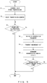
- FIG. 5 is a flowchart that illustrates an example of an operation of the transmitter 10. The process of this flowchart is performed with respect to each transmission frame.
- the transmission frame includes data and a parity bit as illustrated in FIG. 1B , and is generated by the encoder 11. It is assumed that a code type and a coding rate are specified by the controller 15.
- the transmitter 10 performs the first transmission.
- the transmitter 10 encodes data and a portion of a parity bit (the parity bit P1 in the example illustrated in FIG. 1B ) and transmits the encoded bits to the receiver 20. It is assumed that the transmission data length in the first transmission is determined in advance.
- the controller 15 resets a transmission counter. The transmission counter indicates the number of data retransmissions performed on one transmission frame.
- the controller 15 decides whether the receiver 20 is successful in receiving data.
- the receiver 20 returns an ACK (acknowledgement) signal indicating that data reception is successful to the transmitter 10 when the receiver 20 is successful in decoding data.
- the controller 15 decides that the receiver 20 is successful in receiving data when the controller 15 receives the ACK signal from the receiver 20 within a specified time period from the data transmission of the transmitter 10. In this case, the controller 15 terminates the data transmission process performed by the transmitter 10.
- the controller 15 decides that the receiver 20 is not successful in receiving data when the transmitter 10 does not receive the ACK signal from the receiver 20 within the specified time period from the data transmission of the transmitter 10. In this case, the transmitter 10 performs the processes of S4 to S7.
- the controller 15 obtains a retransmission parameter.
- the retransmission parameter is generated by the receiver 20 and reported to the transmitter 10.
- the retransmission parameters reported from the receiver 20 to the transmitter 10 include at least a value that indicates a transmission data length. A method for generating a retransmission parameter will be described later with reference to FIGS. 6 and 7 .
- the transmitter 10 performs a data retransmission according to the retransmission parameter.
- the reader 13 reads a parity bit (that is, a redundancy bit) from the buffer 12 according to the transmission parameter.
- the length of a parity bit read from the buffer 12 corresponds to a transmission data length specified as a retransmission parameter.
- the modulator 14 modulates the redundancy bit output from the reader 13 so as to generate a modulated signal. This modulated signal is output via an antenna after it is upconverted to a radio frequency band (RF band).
- RF band radio frequency band
- the controller 15 increments a transmission counter by one.
- a variable n illustrated in FIG. 5 represents a count value of the transmission counter.
- the controller 15 decides whether the transmission counter has reached a specified upper limit. When the transmission counter has not reached the upper limit, the process performed in the transmitter 10 returns to S3. On the other hand, when the transmission counter has reached the upper limit, the controller 15 terminates the process performed in the transmitter 10.
- the transmitter 10 performs data retransmission repeatedly until the receiver 20 is successful in receiving data or until the transmission counter reaches a specified upper limit in S7.
- a different parity bit (P2, P3, P4, ...) is transmitted every time data retransmission is performed, as illustrated in FIG. 1B .
- the length of a parity bit transmitted in each data retransmission is specified by a retransmission parameter.
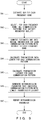
- FIG. 6 is a flowchart that illustrates an example of an operation of the receiver 20.
- the process of this flowchart is performed with respect to each data transmission.
- the process of this flowchart is performed with respect to each data retransmission when data retransmission is performed repeatedly.
- the receiver 20 receives a radio signal transmitted from the transmitter 10.
- the demodulator 22 demodulates the received signal and outputs the demodulated signal.
- the decoder 23 decodes the demodulated signal output from the demodulator 22. In this case, the number of iterations of an iterative decoding in the first data reception is determined in advance and is specified by the controller 25.
- the decoder 23 adds a demodulated signal newly generated by the demodulator 22 (a likelihood value corresponding to a redundancy bit) to a previously generated demodulated signal (likelihood values corresponding to data and a portion of a parity bit).
- the decoder 23 decodes a demodulated signal in which the redundancy bit has been added.
- the number of iterations of the iterative decoding is dynamically determined by the retransmission controller 27.
- the number of iterations of the iterative decoding in the second data transmission is determined in the first data reception.
- the number of iterations of the iterative decoding in the third data transmission is determined in the second data transmission.
- the number of iterations of the iterative decoding in the second and subsequent data transmissions is respectively determined in the immediately previous data transmission.
- the controller 25 decides whether the receiver 20 is successful in receiving data. In the present embodiment, it is decided that data reception is successful when the decoder 23 is successful in properly decoding data. When the controller 25 has decided that the data reception is successful, the receiver 20 transmits an ACK signal to the transmitter 10 in S14. When data reception is not successful, the controller 25 performs the processes of S21 to S27.
- the SNR estimator 26 estimates an SNR of the signal received from the transmitter 10. In this case, the SNR rarely varies greatly with respect to time except for the case in which a wireless communication terminal moves at high speed. Thus, the SNR value obtained in S21 is used by the transmission data length calculator 27b as an estimated SNR for a next data transmission.
- the selector 27a selects all of the communication patterns that satisfy a requested quality.
- the selector 27a refers to quality information stored in the quality information storage 28 so as to select a communication pattern that satisfies a requested quality.
- FIG. 7 illustrates an example of quality information stored in the quality information storage 28.
- the quality information indicates, for example, an error rate for an SNR.
- the error rate is a block error rate (BLER) in the present embodiment.
- BLER block error rate
- the error rate is prepared for each modulation scheme, for each coding rate, and for each number of iterations of an iterative decoding.
- FIG. 7 illustrates an example of an error rate when the modulation scheme is QPSK, the coding rate is 1/2 or 3/4, and the number of iterations of the iterative decoding is 5, 15, or 30.
- the quality information is prepared by, for example, measurement or simulation.
- a combination of a coding rate and the number of iterations of the iterative decoding may hereinafter be referred to as a communication pattern.
- the communication pattern may include a parameter other than a modulation scheme, a coding rate, and the number of iterations of the iterative decoding.
- the communication quality depends on a coding rate and the number of iterations of the iterative decoding, as illustrated in FIG. 7 .
- the error rate is lower if the coding rate is lower.
- the coding rate indicates a length of an information bit with respect to a length of a code word. Further, the error rate becomes lower if the number of iterations of the iterative decoding is increased. Furthermore, the error rate is higher if a higher-order modulation scheme is used (if the number of bits transmitted in one symbol by the modulation scheme is larger), although this is not illustrated.
- the selector 27a selects a communication pattern that satisfies a requested quality. It is preferable that the selector 27a select all of the communication patterns that satisfy the requested quality.
- the requested quality is specified by, for example, a user or a network administrator as a target error rate.
- the selector 27a selects a communication pattern in which an error rate is lower than the target error rate at the estimated SNR obtained by the SNR estimator 26.
- the communication pattern selected in S22 represents a candidate communication pattern applied to a next data transmission.
- the selector 27a selects, from six communication patterns A to F illustrated in FIG. 7 , a communication pattern in which an error rate is lower than a target error rate at the estimated SNR.
- the following are the communication patterns A to F.
- three communication parameters below are a modulation scheme, a coding rate and a number of iterations of an iterative decoding.
- the error rate of the communication pattern A is higher than the target error rate at the estimated SNR.
- each of the error rates of the communication patterns B to F is lower than the target error rate at the estimated SNR.
- the selector 27a selects the communication patterns B to F.
- the transmission data length calculator 27b converts the estimated SNR into mutual information for each communication pattern selected by the selector 27a.
- a method for calculating mutual information that corresponds to an SNR in a communication for which a modulation scheme has been specified is well known, which is described in, for example, J. F. Cheng et al., "Adaptive Incremental Redundancy ".
- the mutual information represents the number of bits transmitted in one symbol and depends on the modulation scheme and the SNR.
- the amount of mutual information depends on the SNR when the modulation scheme is fixed. Specifically, the amount of mutual information is smaller if the SNR is lower.
- FIG. 7 illustrates an example of a correspondence relationship between an SNR and mutual information. The amount of mutual information obtained based on the SNR of a received signal in S23 is used as an estimated mutual information in a next data transmission.
- the mutual information may be calculated from the estimated SNR, or it may be obtained using other methods.
- the correspondence relationship between an SNR and an amount of mutual information is calculated and stored in a table in advance for each communication pattern.
- the transmission data length calculator 27b searches the table using the estimated SNR so as to obtain a corresponding amount of mutual information.
- the transmission data length calculator 27b calculates, for each communication pattern selected by the selector 27a, a transmission data length that indicates a length of a redundancy bit to be transmitted in a next data transmission.
- the transmission data length is calculated using, for example, Formula (1).
- N s,i represents the number of modulation symbols in the i-th data transmission.
- Ci represents an amount of mutual information in the i-th data transmission.
- N s,k+1 (the length of a redundancy bit can be obtained by multiplying this value by the number of bits transmitted in one symbol by a modulation scheme) represents the number of modulation symbols in a next data transmission.
- C k+1 represents an amount of mutual information in a next data transmission.
- the mutual information is calculated from the estimated SNR in the k-th data transmission (that is, calculated from the estimated SNR in the immediately previous data transmission).
- Formula (1) represents a condition under which data is properly decoded in the receiver 20.
- Formula (1) will be satisfied if the transmission data length indicating a length of a redundancy bit in a next data transmission is sufficiently long.
- the transmission data length indicating a length of a redundancy bit be short in order to reduce communication resource and/or to make a transmission latency low.
- the transmission data length calculator 27b determines a transmission data length in a next data transmission such that N s,k+1 is smallest while Formula (1) is satisfied.
- the transmission data length calculator 27b calculates, for each communication pattern, a shortest transmission data length wherein the receiver 20 is expected to successfully receive data.
- the transmission latency calculator 27c calculates a transmission latency for each communication pattern selected by the selector 27a.
- the transmission latency depends on a transmission data length, a code type, and the number of iterations of an iterative decoding. Specifically, the transmission latency is lower if the transmission data length indicating a length of a redundancy bit is shorter. Further, the transmission latency is lower if the number of iterations of an iterative decoding is smaller. It is assumed that the transmission latency can be calculated using a specified formula.
- the retransmission parameter generator 27d identifies, from among the communication patterns selected by the selector 27a, a communication pattern with lowest transmission latency. Then, the retransmission parameter generator 27d generates a retransmission parameter according to the identified communication pattern.
- the retransmission parameters include the number of iterations of an iterative decoding performed in the identified communication pattern, and a transmission data length that is calculated for the identified communication pattern.
- the communication patterns B and C are selected by the selector 27a in the example illustrated in FIG. 7 .
- transmission latencies are calculated for the communication patterns B and C, respectively.
- the transmission latency for the communication pattern B is lower than the transmission latency for the communication pattern C.
- the retransmission parameter generator 27d outputs the "number of iterations of an iterative decoding in the communication pattern B (15)" and the "transmission data length calculated for the communication pattern B" as retransmission parameters.
- the receiver 20 reports the transmission parameters to the transmitter 10.
- the receiver 20 does not need to report a parameter that is used only in the receiver 20 (for example, the number of iterations of an iterative decoding). That is, the receiver 20 may only report the "transmission data length" to the transmitter 10 as a retransmission parameter. Then, the transmitter 10 performs a next data transmission according to this retransmission parameter.
- the controller 25 gives, to the decoder 23, the "number of iterations of an iterative decoding" as a retransmission parameter. Then, according to this retransmission parameter, the decoder 23 decodes a demodulated signal obtained by demodulating a next received signal.
- a retransmission parameter that satisfies a requested quality and in which the transmission latency is lowest is determined in data retransmission. Then, the transmitter 10 transmits data according to this retransmission parameter, and the receiver 20 recovers data from a received signal according to this retransmission parameter. This makes it possible to make the transmission latency lower in a radio environment in which data retransmission is needed.
- a modulation scheme is fixed in order to simplify descriptions, but the first embodiment is not limited to this configuration.
- the modulation scheme in data retransmission may be different from the modulation scheme in the first data transmission.
- the controller 25 may dynamically determine the modulation scheme every time data retransmission is performed.
- the retransmission controller 27 identifies a combination of a modulation scheme, a coding rate, and the number of iterations of an iterative decoding that satisfies a requested quality and in which the transmission latency is lowest, so as to determine a transmission data length, a modulation scheme, and the number of iterations of the iterative decoding that correspond to the identified combination.
- the transmitter 10 modulates a redundancy bit of a specified length with a specified modulation scheme and transmits the modulated redundancy bit to the receiver 20.
- the receiver 20 generates a retransmission parameter.
- the transmitter 10 generates a retransmission parameter.
- the function of the retransmission controller 27 is implemented in the controller 15 and the quality information storage 28 is implemented in the transmitter 10.
- the receiver 20 reports an SNR estimated by the SNR estimator 26 to the transmitter 10.
- the transmitter 10 performs the processes of S22 to S26 illustrated in FIG. 6 in place of S4 in the flowchart illustrated in FIG. 5 .
- the transmitter 10 generates a retransmission parameter according to an estimated SNR.
- the transmitter 10 transmits a redundancy bit according to the retransmission parameter (in this case, a transmission data length) generated by the transmitter 10 itself.
- the transmitter 10 reports the generated retransmission parameter to the receiver 20.
- the receiver 20 receives data according to the reported retransmission parameter (in this case, the number of iterations of an iterative decoding).
- the retransmission parameter is determined such that the transmission latency of each data transmission is lowest.
- a retransmission parameter is determined such that the total transmission latency related to one or more data transmissions is lowest.
- FIG. 8 is a flowchart that illustrates an example of a method for determining a retransmission parameter in the third embodiment.
- the process of the flowchart illustrated in FIG. 8 is performed instead of the processes of S21 to S26 in FIG. 6 .
- the process of this flowchart is performed when the receiver 20 is not successful in receiving data.
- the process of the flowchart illustrated in FIG. 8 is performed in the receiver 20.
- the process of the flowchart illustrated in FIG. 8 may be performed in the transmitter 10 excepting the process of S31.
- the SNR estimator 26 estimates an SNR of a signal received from the transmitter 10.
- the retransmission controller 27 decides whether a difference between the estimated SNR and a predicted SNR is greater than a specified threshold.
- An initial value of the predicted SNR is, for example, an expected maximum value of an SNR.
- the retransmission controller 27 predicts a future SNR in S33.
- the future SNR is calculated by, for example, performing extrapolation using one or more estimated SNRs in the past and a current estimated SNR.
- the retransmission controller 27 In S34-1, the retransmission controller 27 generates a retransmission parameter for the case in which a transmission of a redundancy bit is performed once. This process is substantially the same as the processes of S22 to S26 illustrated in FIG. 6 . In other words, a combination of a "transmission data length" and the “number of iterations of an iterative decoding" that satisfies a requested quality and in which the transmission latency is lowest is determined.
- the retransmission controller 27 generates a retransmission parameter for the case in which a transmission of a redundancy bit is performed twice.
- This process is also substantially the same as the processes of S22 to S26 illustrated in FIG. 6 .
- a transmission of a redundancy bit is performed twice, a parity bit having a length that is the transmission data length calculated in S24 is divided into two portions and they are sequentially transmitted.
- a transmission latency is calculated while taking this division into consideration. For example, when the transmission data length calculated in S24 is 50 bits, a value twice the transmission latency for the case in which a parity bit of 25 bits is transmitted is calculated.
- the retransmission controller 27 While changing the number of data transmissions, the retransmission controller 27 generates a retransmission parameter for each case.
- a variable k used in this flowchart is obtained by subtracting the number of performed transmissions from a maximum value of the number of transmissions. This results in generating a retransmission parameter for each of the cases in which a transmission of a redundancy bit is performed once to k times.
- the retransmission controller 27 selects, from among the retransmission parameters generated in S34-1 to S34-k, a retransmission parameter with lowest transmission latency. Then, the retransmission controller 27 outputs the selected retransmission parameter.
- the transmitter 10 transmits a redundancy bit of a specified length a specified number of times.
- the receiver 20 performs decoding a specified number of times for each data transmission.
- a retransmission parameter is determined such that the total transmission latency related to one or more data transmissions is lowest. This results in making the total data transmission time shorter while satisfying a requested quality.
- the wireless communication system can transmit data using a plurality of frequency bands in parallel.
- the wireless communication system 1 can transmit data using two or more frequency bands from among a 920MHz band, a 2.4GHz band, and a 5GHz band at the same time.
- FIG. 9 is a flowchart that illustrates an example of a method for determining a retransmission parameter in the fourth embodiment.
- the process of the flowchart illustrated in FIG. 9 is performed instead of the processes of S21 to S27 in FIG. 6 .
- the process of this flowchart is performed when the receiver 20 is not successful in receiving data.
- the process of the flowchart illustrated in FIG. 9 is performed in the receiver 20.
- the process of the flowchart illustrated in FIG. 9 may be performed in the transmitter 10 excepting the process of S41.
- the processes of S41 to S43 are substantially the same as the processes of S21 to S23 illustrated in FIG. 6 . However, the processes of S41 to S43 are performed for each frequency band.
- the SNR estimator 26 estimates, for each frequency band, an SNR of a signal received from the transmitter 10.
- the selector 27a selects, for each frequency band, a communication pattern that satisfies a requested quality.
- the transmission data length calculator 27b calculates mutual information for each of the communication patterns selected by the selector 27a.
- the transmission data length calculator 27b calculates, for each of the communication patterns selected by the selector 27a, a transmission data length that indicates a length of a redundancy bit to be transmitted in a next data transmission.
- the transmission data length is calculated based on the sum of the amounts of mutual information of the respective frequency bands. In other words, the transmission data length is calculated using Formula (2).
- the modulation schemes for the respective frequency bands may be the same as one another, or they may be different from one another.
- R 1 represents a data rate (the number of bits per symbol) in the first data transmission and is specified in advance.
- N s,i represents the number of modulation symbols in the i-th data transmission.
- C i,j represents an amount of mutual information in the i-th data transmission in a frequency band j.
- N s,k+1 (the length of a redundancy bit can be obtained by multiplying this value by the number of bits transmitted in one symbol by a modulation scheme) represents the number of modulation symbols in a next data transmission.
- C k+1,j represents an amount of mutual information in a next data transmission in the frequency band j.
- the mutual information is calculated from the estimated SNR in the k-th data transmission.
- the transmission latency calculator 27c calculates a transmission latency for each of the communication patterns selected by the selector 27a.
- the retransmission parameter generator 27d identifies, from among the communication patterns selected by the selector 27a, a communication pattern with lowest transmission latency.
- the retransmission parameter generator 27d generates a retransmission parameter for the identified communication pattern. Then, the receiver 20 reports the retransmission parameter to the transmitter 10.
- the transmitter 10 transmits a next redundancy bit to the receiver 20 according to the retransmission parameter reported by the receiver 20.
- the redundancy bit is transmitted using a plurality of frequency bands.
- lengths (N s,k+1 ) of a redundancy bit that are transmitted using the plurality of frequency bands are the same as one another.
- data transmission is performed using a plurality of frequency bands, but data transmission may be performed using one of the plurality of frequency bands.
- the retransmission controller 27 selects, from among the communication patterns selected for all of the plurality of frequency bands, a communication pattern with lowest transmission latency. In other words, with respect to each of the plurality of frequency bands, the retransmission controller 27 calculates a transmission data length and a transmission latency for each of the communication patterns selected by the selector 27a.
- the retransmission controller 27 identifies, from among all of the communication patterns, a communication pattern with lowest transmission latency and determines retransmission parameters (a frequency band, a transmission data length, and the number of iterations of an iterative decoding) that correspond to the identified communication pattern.
- a retransmission control obtained by combining the third and fourth embodiments may be performed.
- retransmission parameters for a plurality of frequency bands may be determined such that the sum of the latencies until reception is successful is lowest.
- the wireless communication system according to a fifth embodiment is a wireless LAN system that employs CSMA/CA. Further, a retransmission parameter is generated in the receiver 20. In other words, a retransmission parameter is reported from the receiver 20 to the transmitter 10.
- FIG. 10 illustrates an example of a retransmission control performed in a wireless LAN system that employs CSMA/CA.
- a source terminal such as the wireless communication device 2 obtains a transmission right and transmits data to a destination terminal (such as the wireless communication device 3) .
- a wireless resource is in use during a "busy" due to other communications.
- a time period (a contention window: CW) in which a transmission right is to be obtained is set. It is assumed that the source terminal obtains a transmission right during this contention window.
- the source terminal transmits an RTS (request to send) frame to the destination terminal.
- the RTS frame includes a frame control, time period information (duration), destination terminal information (receiver address: RA), source terminal information (transceiver address: TA), and a frame check sequence (FCS) .
- the "Duration" specifies a time period in which other terminals are prohibited from performing transmission (network allocation vector: NAV) .
- the destination terminal When the destination terminal receives the RTS frame from the transmission terminal, the destination terminal returns a CTS (clear to send) frame to the source terminal after a short inter-frame space (SIFS) has elapsed.
- the CTS frame includes a frame control, Duration, RA, and FCS.
- the source terminal When the source terminal receives the CTS frame from the destination terminal, the source terminal transmits data to the destination terminal after an SIFS has elapsed. In this example, the destination terminal is not successful in receiving data. In this case, the destination terminal does not transmit an ACK frame to the transmission terminal. In other words, the source terminal does not receive an ACK frame from the destination terminal. When the source terminal does not receive an ACK frame within a specified time period since the data transmission, the source terminal decides that data retransmission is needed.
- the source terminal When the source terminal obtains a transmission right during the CW, the source terminal transmits an RTS frame to the destination terminal again.
- the source terminal receives a CTS frame from the destination terminal, the source terminal transmits the same data as last time to the destination terminal after an SIFS has elapsed.
- the destination terminal When the destination terminal is successful in receiving data, the destination terminal transmits an ACK frame to the source terminal.
- the source terminal In the sequence illustrated in FIG. 10 , there is a need for the source terminal to obtain a transmission right again when the destination terminal is not successful in receiving data.
- the source terminal is not always able to immediately obtain a transmission right during a next CW. Thus, there is a possibility that it will take a long time to perform a retransmission control.
- FIG. 12 illustrates an example of a retransmission control according to the fifth embodiment.
- the source terminal and the destination terminal perform a retransmission control according to the first, third, or fourth embodiment.
- the operation of obtaining a transmission right and transmitting data to the source terminal is substantially the same in FIGS. 10 and 12 , so the descriptions are omitted.
- the destination terminal When the destination terminal is not successful in receiving data, the destination terminal generates a retransmission parameter.
- the retransmission parameter is generated by, for example, the method illustrated in FIG. 6 , 8 , or 9 . Further, the destination terminal transmits a CTS frame to the source terminal.
- This CTS frame is used as a negative ACK (NACK).
- NACK negative ACK
- This frame may hereinafter be referred to as a CTS/NACK frame.
- the CTS/NACK frame has the same configuration as the frame illustrated in FIG. 11B (that is, a usual CTS frame).
- a transmission prohibiting time period (Network Allocation Vector: NAV) that is set in the "duration" in the CTS/NACK frame is calculated from a transmission latency between the transmitter 10 and the receiver 20 (including a time needed to propagate a signal from the transmitter 10 to the receiver 20, a time of processing performed by the demodulator 22, and a time of processing performed by the decoder 23, as in the first embodiment) that is calculated from retransmission parameters (a transmission data length, a coding rate, and the number of iterations of an iterative decoding), and from a time needed to process a CSMA/CA sequence (such as an SIFS and an ACK transmission time) .
- NAV Network Allocation Vector
- the source terminal back-calculates a transmission data length in a next data transmission from the NAV set in the "duration" in the received CTS/NACK frame. It is assumed that, in this example, the transmitter 10 includes the quality information storage 28 in order to back-calculate a transmission data length.
- a CTS/NACK frame transmitted from the destination terminal has the same header as a usual CTS frame.
- a NAV is set in the header of the CTS/NACK frame as time period information.
- the NAV indicates a time period in which wireless communication devices other than a wireless communication device specified by the RA in the CTS/NACK frame are prohibited from performing transmission until a specified time period elapses.
- each terminal that receives the CTS/NACK frame is prohibited from transmitting a signal during a time period specified by the NAV.
- the source terminal is specified by the RA in the CTS/NACK frame.
- the source terminal is allowed to transmit a signal even during the time period specified by the NAV.
- the source terminal transmits a redundancy bit according to the retransmission parameter reported by a CTS/NACK frame. For example, when the transmission data length is represented using a NAV, the source terminal calculates the transmission data length based on the NAV and transmits a redundancy bit of the calculated transmission data length to the destination terminal. Here, the source terminal may calculate the transmission data length from a time period corresponding to the NAV, using the quality information storage 28. When the destination terminal is successful in receiving data, the destination terminal transmits an ACK frame to the source terminal. Note that when the transmission data length is reported as a retransmission parameter, the source terminal transmits a redundancy bit of the reported length to the destination terminal.
- a CTS/NACK frame is output from the destination terminal, and a wireless resource is allocated to a communication between the source terminal and the destination terminal.
- the source terminal can immediately transmit a redundancy bit without newly obtaining a transmission right in the contention window.
- a retransmission parameter is reported from the destination terminal to the source terminal using a CTS/NACK frame.
- an overhead for reporting a retransmission parameter is reduced.
Landscapes
- Engineering & Computer Science (AREA)
- Computer Networks & Wireless Communication (AREA)
- Signal Processing (AREA)
- Quality & Reliability (AREA)
- Detection And Prevention Of Errors In Transmission (AREA)
- Mobile Radio Communication Systems (AREA)
Claims (6)
- Drahtloses Kommunikationssystem, in dem codierte Bits von einer ersten drahtlosen Kommunikationsvorrichtung (10) zu einer zweiten drahtlosen Kommunikationsvorrichtung (20) übertragen werden und Redundanzinformationen zum Decodieren der codierten Bits von der ersten drahtlosen Kommunikationsvorrichtung zu der zweiten drahtlosen Kommunikationsvorrichtung übertragen werden, wenn die zweite drahtlose Kommunikationsvorrichtung die codierten Bits nicht decodieren kann, wobei das drahtlose Kommunikationssystem Folgendes umfasst:eine Auswahleinrichtung (27a), die konfiguriert ist, ein oder mehrere Kommunikationsmuster auszuwählen, die jeweils eine angeforderte Qualität erfüllen, wobei jedes der Kommunikationsmuster eine Kombination einer Vielzahl von Parametern einschließlich einer Codierungsrate und einer Anzahl von Iterationen einer iterativen Decodierung anzeigt;einen Übertragungsdatenlängenrechner (27b), der konfiguriert ist, für jedes der von der Auswahleinrichtung ausgewählten Kommunikationsmuster eine Übertragungsdatenlänge zu berechnen, die eine Länge der Redundanzinformationen angibt, wobei die zweite drahtlose Kommunikationsvorrichtung die codierten Bits erwartungsgemäß durch Verwenden der Redundanzinformationen erfolgreich decodiert;einen Übertragungslatenzrechner (27c), der konfiguriert ist, für jedes der von der Auswahleinrichtung ausgewählten Kommunikationsmuster eine Übertragungslatenz zwischen der ersten drahtlosen Kommunikationsvorrichtung und der zweiten drahtlosen Kommunikationsvorrichtung auf der Grundlage der von dem Übertragungsdatenlängenrechner berechneten Übertragungsdatenlänge zu berechnen, wobei die Übertragungslatenz eine Zeit, die benötigt wird, um ein Signal von der ersten drahtlosen Kommunikationsvorrichtung zu der zweiten drahtlosen Kommunikationsvorrichtung zu verbreiten, eine Zeit einer Verarbeitung, die von einem Demodulator der zweiten drahtlosen Kommunikationsvorrichtung durchgeführt wird, und eine Zeit einer Verarbeitung einschließt, die von einem Decodierer der zweiten drahtlosen Kommunikationsvorrichtung durchgeführt wird; undeinen Neuübertragungsparametergenerator (27d), der konfiguriert ist, einen Neuübertragungsparameter zu generieren, der ein Kommunikationsmuster mit der niedrigsten Übertragungslatenz unter den von der Auswahleinrichtung ausgewählten Kommunikationsmustern anzeigt, wobeidie erste drahtlose Kommunikationsvorrichtung die Redundanzinformationen gemäß dem Neuübertragungsparameter überträgt, unddie zweite drahtlose Kommunikationsvorrichtung die codierten Bits unter Verwendung der Redundanzinformationen gemäß dem Neuübertragungsparameter decodiert.
- Drahtloses Kommunikationssystem nach Anspruch 1, wobei
der Neuübertragungsparameter eine Übertragungsdatenlänge und eine Anzahl von Iterationen der iterativen Decodierung enthält, die dem Kommunikationsmuster mit der niedrigsten Übertragungslatenz entsprechen,
die erste drahtlose Kommunikationsvorrichtung die Redundanzinformationen gemäß der Übertragungsdatenlänge, die in dem Neuübertragungsparameter enthalten ist, überträgt, und
die zweite drahtlose Kommunikationsvorrichtung die codierten Bits unter Verwendung der Redundanzinformationen gemäß der Anzahl von Iterationen der iterativen Decodierung decodiert, die in dem Neuübertragungsparameter enthalten sind. - Drahtloses Kommunikationssystem nach Anspruch 1, wobei
der Neuübertragungsparameter ein Modulationsschema, eine Übertragungsdatenlänge und eine Anzahl von Iterationen der iterativen Decodierung enthält, die dem Kommunikationsmuster mit der niedrigsten Übertragungslatenz entsprechen,
die erste drahtlose Kommunikationsvorrichtung die Redundanzinformationen gemäß dem Modulationsschema und der Übertragungsdatenlänge, die in dem Neuübertragungsparameter enthalten ist, überträgt, und
die zweite drahtlose Kommunikationsvorrichtung die codierten Bits unter Verwendung der Redundanzinformationen gemäß der Anzahl von Iterationen der iterativen Decodierung decodiert, die in dem Neuübertragungsparameter enthalten sind. - Drahtloses Kommunikationssystem nach einem der Ansprüche 1 bis 3, wobei
die codierten Bits unter Verwendung einer Vielzahl von Frequenzbändern von der ersten drahtlosen Kommunikationsvorrichtung zu der zweiten drahtlosen Kommunikationsvorrichtung übertragen werden,
die Auswahleinrichtung für jedes der Vielzahl von Frequenzbänder ein oder mehrere Kommunikationsmuster auswählt, die jeweils die angeforderte Qualität erfüllen,
der Übertragungsdatenlängenrechner für jedes der von der Auswahleinrichtung ausgewählten Kommunikationsmuster eine Übertragungsdatenlänge berechnet, die eine Länge von Redundanzinformationen angibt, wobei die zweite drahtlose Kommunikationsvorrichtung die codierten Bits erwartungsgemäß durch Verwenden der Redundanzinformationen erfolgreich decodiert,
der Übertragungslatenzrechner für jedes der von der Auswahleinrichtung ausgewählten Kommunikationsmuster eine Übertragungslatenz zwischen der ersten drahtlosen Kommunikationsvorrichtung und der zweiten drahtlosen Kommunikationsvorrichtung auf der Grundlage der von dem Übertragungsdatenlängenrechner berechneten Übertragungsdatenlänge berechnet, und
der Neuübertragungsparametergenerator aus Kombinationen von Kommunikationsmustern, von denen jedes aus den für jedes der Vielzahl von Frequenzbänder ausgewählten Kommunikationsmustern ausgewählt ist, eine Kombination von Kommunikationsmustern mit der niedrigsten Übertragungslatenz identifiziert und einen Neuübertragungsparameter generiert, der jedem der Kommunikationsmuster entspricht, die in der identifizierten Kombination enthalten sind. - Drahtloses Kommunikationssystem nach Anspruch 1, wobei
der Übertragungslatenzberechner die gesamten Latenzen für eine Vielzahl von Fällen berechnet, in denen sich die Anzahl der erneuten Übertragungen voneinander unterscheidet, und
der Neuübertragungsparametergenerator eine Anzahl von Neuübertragungen bestimmt, bei denen die Gesamtlatenz am niedrigsten ist. - Neuübertragungsparameter-Bestimmungsvorrichtung (25), die in einem drahtlosen Kommunikationssystem verwendet wird, in dem codierte Bits von einer ersten drahtlosen Kommunikationsvorrichtung zu einer zweiten drahtlosen Kommunikationsvorrichtung übertragen werden und Redundanzinformationen zum Decodieren der codierten Bits von der ersten drahtlosen Kommunikationsvorrichtung zu der zweiten drahtlosen Kommunikationsvorrichtung übertragen werden, wenn die zweite drahtlose Kommunikationsvorrichtung die codierten Bits nicht decodieren kann, wobei die Neuübertragungsparameter-Bestimmungsvorrichtung Folgendes umfasst:eine Auswahleinrichtung (27a), die konfiguriert ist, ein oder mehrere Kommunikationsmuster auszuwählen, die jeweils eine angeforderte Qualität erfüllen, wobei jedes der Kommunikationsmuster eine Kombination einer Vielzahl von Parametern einschließlich einer Codierungsrate und einer Anzahl von Iterationen einer iterativen Decodierung anzeigt;einen Übertragungsdatenlängenrechner (27b), der konfiguriert ist, für jedes der von der Auswahleinrichtung ausgewählten Kommunikationsmuster eine Übertragungsdatenlänge zu berechnen, die eine Länge der Redundanzinformationen angibt, wobei die zweite drahtlose Kommunikationsvorrichtung die codierten Bits erwartungsgemäß durch Verwenden der Redundanzinformationen erfolgreich decodiert;einen Übertragungslatenzrechner (27c), der konfiguriert ist, für jedes der von der Auswahleinrichtung ausgewählten Kommunikationsmuster eine Übertragungslatenz zwischen der ersten drahtlosen Kommunikationsvorrichtung und der zweiten drahtlosen Kommunikationsvorrichtung auf der Grundlage der von dem Übertragungsdatenlängenrechner berechneten Übertragungsdatenlänge zu berechnen, wobei die Übertragungslatenz eine Zeit, die benötigt wird, um ein Signal von der ersten drahtlosen Kommunikationsvorrichtung zu der zweiten drahtlosen Kommunikationsvorrichtung zu verbreiten, eine Zeit einer Verarbeitung, die von einem Demodulator der zweiten drahtlosen Kommunikationsvorrichtung durchgeführt wird, und eine Zeit einer Verarbeitung einschließt, die von einem Decodierer der zweiten drahtlosen Kommunikationsvorrichtung durchgeführt wird; undeinen Neuübertragungsparametergenerator (27d), der konfiguriert ist, einen Neuübertragungsparameter zu generieren, der ein Kommunikationsmuster mit der niedrigsten Übertragungslatenz unter den von der Auswahleinrichtung ausgewählten Kommunikationsmustern anzeigt.
Applications Claiming Priority (1)
| Application Number | Priority Date | Filing Date | Title |
|---|---|---|---|
| JP2017161357A JP6991784B2 (ja) | 2017-08-24 | 2017-08-24 | 無線通信システム、再送パラメータ決定装置、および再送パラメータ通知方法 |
Publications (2)
| Publication Number | Publication Date |
|---|---|
| EP3447946A1 EP3447946A1 (de) | 2019-02-27 |
| EP3447946B1 true EP3447946B1 (de) | 2019-09-18 |
Family
ID=61521284
Family Applications (1)
| Application Number | Title | Priority Date | Filing Date |
|---|---|---|---|
| EP18155727.3A Active EP3447946B1 (de) | 2017-08-24 | 2018-02-08 | Wiederübertragungsparameterbestimmung |
Country Status (3)
| Country | Link |
|---|---|
| US (1) | US10608787B2 (de) |
| EP (1) | EP3447946B1 (de) |
| JP (1) | JP6991784B2 (de) |
Families Citing this family (9)
| Publication number | Priority date | Publication date | Assignee | Title |
|---|---|---|---|---|
| EP3837786B1 (de) * | 2018-09-27 | 2022-11-23 | Sony Group Corporation | Infrastrukturausrüstung, kommunikationsvorrichtung und -verfahren |
| CN111385057B (zh) * | 2018-12-27 | 2023-05-09 | 中兴通讯股份有限公司 | 一种数据的重传解码方法、装置、系统及通信设备 |
| KR102828624B1 (ko) * | 2019-06-05 | 2025-07-04 | 에스케이하이닉스 주식회사 | 크로스토크로 인한 데이터 에러가 억제되는 데이터 전송 시스템 및 데이터 전송 방법 |
| US11202314B2 (en) * | 2019-06-18 | 2021-12-14 | Sony Group Corporation | Immediate retransmission scheme for real time applications |
| US11464054B2 (en) | 2019-07-24 | 2022-10-04 | Sony Group Corporation | RTA contention collision avoidance |
| DE102019133894A1 (de) * | 2019-12-11 | 2021-06-17 | Beckhoff Automation Gmbh | Verfahren zum zyklischen Übertragen von Daten zwischen Kommunikationsteilnehmern auf einem Datenübertragungskanal und Datenübertragungssystem |
| JP7395379B2 (ja) | 2020-02-07 | 2023-12-11 | キヤノン株式会社 | 通信装置、制御方法、およびプログラム |
| US20230147839A1 (en) * | 2020-03-18 | 2023-05-11 | Beijing Xiaomi Mobile Software Co., Ltd. | Data transmission method and apparatus, communication device, and storage medium |
| WO2025011742A1 (en) * | 2023-07-10 | 2025-01-16 | Nokia Technologies Oy | Harq assistance information feedback for fast data recovery |
Family Cites Families (11)
| Publication number | Priority date | Publication date | Assignee | Title |
|---|---|---|---|---|
| JP2002026879A (ja) | 2000-07-05 | 2002-01-25 | Seiko Epson Corp | データ誤り訂正装置 |
| US7813322B2 (en) | 2003-02-19 | 2010-10-12 | Qualcomm Incorporated | Efficient automatic repeat request methods and apparatus |
| US7630731B2 (en) * | 2003-09-08 | 2009-12-08 | Lundby Stein A | Apparatus, system, and method for managing reverse link communication |
| WO2009005047A1 (ja) | 2007-07-04 | 2009-01-08 | Nec Corporation | マルチキャリア移動体通信システム |
| US8004992B2 (en) | 2008-03-03 | 2011-08-23 | Qualcomm Incorporated | Adding hybrid ARQ to WLAN protocols with MAC based feedback |
| KR101530712B1 (ko) | 2008-03-31 | 2015-06-24 | 엘지전자 주식회사 | Harq를 이용한 데이터 전송방법 |
| US8650448B2 (en) * | 2009-10-13 | 2014-02-11 | Intel Corporation | Retransmission techniques in wireless networks |
| US9433016B2 (en) * | 2013-06-25 | 2016-08-30 | Futurewei Technologies, Inc. | System and method for detecting and resolving conflicts |
| WO2016120215A1 (en) | 2015-01-26 | 2016-08-04 | Sony Corporation | Receiver for receiving data in a broadcast system using redundancy data |
| US10111258B2 (en) | 2015-02-13 | 2018-10-23 | Qualcomm Incorporated | Methods and systems for receiver initiated protection of a wireless communication exchange |
| US9948430B2 (en) * | 2015-03-17 | 2018-04-17 | Huawei Technologies Co., Ltd. | Method and apparatus for combining data and retransmission data in layer domain |
-
2017
- 2017-08-24 JP JP2017161357A patent/JP6991784B2/ja active Active
-
2018
- 2018-02-08 US US15/891,849 patent/US10608787B2/en active Active
- 2018-02-08 EP EP18155727.3A patent/EP3447946B1/de active Active
Non-Patent Citations (1)
| Title |
|---|
| None * |
Also Published As
| Publication number | Publication date |
|---|---|
| US10608787B2 (en) | 2020-03-31 |
| EP3447946A1 (de) | 2019-02-27 |
| JP2019041220A (ja) | 2019-03-14 |
| US20190068326A1 (en) | 2019-02-28 |
| JP6991784B2 (ja) | 2022-01-13 |
Similar Documents
| Publication | Publication Date | Title |
|---|---|---|
| EP3447946B1 (de) | Wiederübertragungsparameterbestimmung | |
| EP1494385B1 (de) | Verfahren und Vorrichtung zur Leistungsverbesserung der Ablaufsteuerungsleistung in drahtlosen Paketdatensystemen | |
| US7768988B2 (en) | Method and apparatus to perform network medium reservation in a wireless network | |
| EP1924009B1 (de) | Relais zum Weiterleiten eines Datenpaketes gesendet von einem ersten Sender/Empfänger an einen zweiten Sender/Empfänger. | |
| US7339949B2 (en) | ARQ transmission and reception methods and apparatus | |
| US8554148B2 (en) | Data transmission/reception apparatus and method for wireless communication system | |
| US7693099B2 (en) | Methods of wireless communication | |
| US20050268181A1 (en) | Method and apparatus to provide adaptive transmission parameters for wireless networks | |
| US20150245360A1 (en) | Staged multi-user grouping for multiple-input, multiple-output wireless communications | |
| EP3214785B1 (de) | Linkanpassung in drahtloskommunikationen | |
| EP2257087A1 (de) | Drahtloses endgerät und weiterübertragungsverfahren | |
| CN100474792C (zh) | 具有发射机和发射天线的无线电发射设备 | |
| US11013032B2 (en) | Wireless communication device and communication parameter report method | |
| JP4035527B2 (ja) | 通信端末装置及び通信方法 | |
| US8750214B2 (en) | Method and base station for detecting a HARQ-ACK codeword | |
| US20120134285A1 (en) | Radio communication appratus, radio communication system, and radio communication method in radio communication apparatus | |
| US20220345262A1 (en) | Method for harq transmission | |
| KR102124610B1 (ko) | 무선 통신 시스템에서 낮은 복잡도로 복호를 수행하기 위한 방법 및 장치 | |
| WO2008053731A1 (en) | Wireless communication method and apparatus thereof | |
| JP5366761B2 (ja) | 無線通信装置及び無線通信方法 | |
| WO2017056446A1 (ja) | 通信装置、通信システム、制御方法及び通信プログラム | |
| JP6831272B2 (ja) | 無線通信装置および無線通信方法 | |
| WO2008069574A1 (en) | Apparatus and method of transmitting and receiving reception acknowledgment signal in mobile communication system |
Legal Events
| Date | Code | Title | Description |
|---|---|---|---|
| PUAI | Public reference made under article 153(3) epc to a published international application that has entered the european phase |
Free format text: ORIGINAL CODE: 0009012 |
|
| STAA | Information on the status of an ep patent application or granted ep patent |
Free format text: STATUS: THE APPLICATION HAS BEEN PUBLISHED |
|
| AK | Designated contracting states |
Kind code of ref document: A1 Designated state(s): AL AT BE BG CH CY CZ DE DK EE ES FI FR GB GR HR HU IE IS IT LI LT LU LV MC MK MT NL NO PL PT RO RS SE SI SK SM TR |
|
| AX | Request for extension of the european patent |
Extension state: BA ME |
|
| STAA | Information on the status of an ep patent application or granted ep patent |
Free format text: STATUS: REQUEST FOR EXAMINATION WAS MADE |
|
| REG | Reference to a national code |
Ref country code: DE Ref legal event code: R079 Ref document number: 602018000645 Country of ref document: DE Free format text: PREVIOUS MAIN CLASS: H04L0001000000 Ipc: H04L0001180000 |
|
| 17P | Request for examination filed |
Effective date: 20190321 |
|
| RBV | Designated contracting states (corrected) |
Designated state(s): AL AT BE BG CH CY CZ DE DK EE ES FI FR GB GR HR HU IE IS IT LI LT LU LV MC MK MT NL NO PL PT RO RS SE SI SK SM TR |
|
| GRAP | Despatch of communication of intention to grant a patent |
Free format text: ORIGINAL CODE: EPIDOSNIGR1 |
|
| STAA | Information on the status of an ep patent application or granted ep patent |
Free format text: STATUS: GRANT OF PATENT IS INTENDED |
|
| RIC1 | Information provided on ipc code assigned before grant |
Ipc: H04L 1/16 20060101ALI20190416BHEP Ipc: H04L 1/00 20060101ALI20190416BHEP Ipc: H04L 1/18 20060101AFI20190416BHEP Ipc: H04W 74/08 20090101ALN20190416BHEP |
|
| INTG | Intention to grant announced |
Effective date: 20190514 |
|
| GRAS | Grant fee paid |
Free format text: ORIGINAL CODE: EPIDOSNIGR3 |
|
| GRAA | (expected) grant |
Free format text: ORIGINAL CODE: 0009210 |
|
| STAA | Information on the status of an ep patent application or granted ep patent |
Free format text: STATUS: THE PATENT HAS BEEN GRANTED |
|
| AK | Designated contracting states |
Kind code of ref document: B1 Designated state(s): AL AT BE BG CH CY CZ DE DK EE ES FI FR GB GR HR HU IE IS IT LI LT LU LV MC MK MT NL NO PL PT RO RS SE SI SK SM TR |
|
| REG | Reference to a national code |
Ref country code: GB Ref legal event code: FG4D |
|
| REG | Reference to a national code |
Ref country code: CH Ref legal event code: EP |
|
| REG | Reference to a national code |
Ref country code: DE Ref legal event code: R096 Ref document number: 602018000645 Country of ref document: DE |
|
| REG | Reference to a national code |
Ref country code: AT Ref legal event code: REF Ref document number: 1182574 Country of ref document: AT Kind code of ref document: T Effective date: 20191015 |
|
| REG | Reference to a national code |
Ref country code: IE Ref legal event code: FG4D |
|
| REG | Reference to a national code |
Ref country code: NL Ref legal event code: MP Effective date: 20190918 |
|
| PG25 | Lapsed in a contracting state [announced via postgrant information from national office to epo] |
Ref country code: FI Free format text: LAPSE BECAUSE OF FAILURE TO SUBMIT A TRANSLATION OF THE DESCRIPTION OR TO PAY THE FEE WITHIN THE PRESCRIBED TIME-LIMIT Effective date: 20190918 Ref country code: HR Free format text: LAPSE BECAUSE OF FAILURE TO SUBMIT A TRANSLATION OF THE DESCRIPTION OR TO PAY THE FEE WITHIN THE PRESCRIBED TIME-LIMIT Effective date: 20190918 Ref country code: SE Free format text: LAPSE BECAUSE OF FAILURE TO SUBMIT A TRANSLATION OF THE DESCRIPTION OR TO PAY THE FEE WITHIN THE PRESCRIBED TIME-LIMIT Effective date: 20190918 Ref country code: NO Free format text: LAPSE BECAUSE OF FAILURE TO SUBMIT A TRANSLATION OF THE DESCRIPTION OR TO PAY THE FEE WITHIN THE PRESCRIBED TIME-LIMIT Effective date: 20191218 Ref country code: BG Free format text: LAPSE BECAUSE OF FAILURE TO SUBMIT A TRANSLATION OF THE DESCRIPTION OR TO PAY THE FEE WITHIN THE PRESCRIBED TIME-LIMIT Effective date: 20191218 Ref country code: LT Free format text: LAPSE BECAUSE OF FAILURE TO SUBMIT A TRANSLATION OF THE DESCRIPTION OR TO PAY THE FEE WITHIN THE PRESCRIBED TIME-LIMIT Effective date: 20190918 |
|
| REG | Reference to a national code |
Ref country code: LT Ref legal event code: MG4D |
|
| PG25 | Lapsed in a contracting state [announced via postgrant information from national office to epo] |
Ref country code: AL Free format text: LAPSE BECAUSE OF FAILURE TO SUBMIT A TRANSLATION OF THE DESCRIPTION OR TO PAY THE FEE WITHIN THE PRESCRIBED TIME-LIMIT Effective date: 20190918 Ref country code: LV Free format text: LAPSE BECAUSE OF FAILURE TO SUBMIT A TRANSLATION OF THE DESCRIPTION OR TO PAY THE FEE WITHIN THE PRESCRIBED TIME-LIMIT Effective date: 20190918 Ref country code: RS Free format text: LAPSE BECAUSE OF FAILURE TO SUBMIT A TRANSLATION OF THE DESCRIPTION OR TO PAY THE FEE WITHIN THE PRESCRIBED TIME-LIMIT Effective date: 20190918 Ref country code: GR Free format text: LAPSE BECAUSE OF FAILURE TO SUBMIT A TRANSLATION OF THE DESCRIPTION OR TO PAY THE FEE WITHIN THE PRESCRIBED TIME-LIMIT Effective date: 20191219 |
|
| REG | Reference to a national code |
Ref country code: AT Ref legal event code: MK05 Ref document number: 1182574 Country of ref document: AT Kind code of ref document: T Effective date: 20190918 |
|
| PG25 | Lapsed in a contracting state [announced via postgrant information from national office to epo] |
Ref country code: IT Free format text: LAPSE BECAUSE OF FAILURE TO SUBMIT A TRANSLATION OF THE DESCRIPTION OR TO PAY THE FEE WITHIN THE PRESCRIBED TIME-LIMIT Effective date: 20190918 Ref country code: EE Free format text: LAPSE BECAUSE OF FAILURE TO SUBMIT A TRANSLATION OF THE DESCRIPTION OR TO PAY THE FEE WITHIN THE PRESCRIBED TIME-LIMIT Effective date: 20190918 Ref country code: PL Free format text: LAPSE BECAUSE OF FAILURE TO SUBMIT A TRANSLATION OF THE DESCRIPTION OR TO PAY THE FEE WITHIN THE PRESCRIBED TIME-LIMIT Effective date: 20190918 Ref country code: RO Free format text: LAPSE BECAUSE OF FAILURE TO SUBMIT A TRANSLATION OF THE DESCRIPTION OR TO PAY THE FEE WITHIN THE PRESCRIBED TIME-LIMIT Effective date: 20190918 Ref country code: NL Free format text: LAPSE BECAUSE OF FAILURE TO SUBMIT A TRANSLATION OF THE DESCRIPTION OR TO PAY THE FEE WITHIN THE PRESCRIBED TIME-LIMIT Effective date: 20190918 Ref country code: ES Free format text: LAPSE BECAUSE OF FAILURE TO SUBMIT A TRANSLATION OF THE DESCRIPTION OR TO PAY THE FEE WITHIN THE PRESCRIBED TIME-LIMIT Effective date: 20190918 Ref country code: AT Free format text: LAPSE BECAUSE OF FAILURE TO SUBMIT A TRANSLATION OF THE DESCRIPTION OR TO PAY THE FEE WITHIN THE PRESCRIBED TIME-LIMIT Effective date: 20190918 Ref country code: PT Free format text: LAPSE BECAUSE OF FAILURE TO SUBMIT A TRANSLATION OF THE DESCRIPTION OR TO PAY THE FEE WITHIN THE PRESCRIBED TIME-LIMIT Effective date: 20200120 |
|
| PG25 | Lapsed in a contracting state [announced via postgrant information from national office to epo] |
Ref country code: CZ Free format text: LAPSE BECAUSE OF FAILURE TO SUBMIT A TRANSLATION OF THE DESCRIPTION OR TO PAY THE FEE WITHIN THE PRESCRIBED TIME-LIMIT Effective date: 20190918 Ref country code: SK Free format text: LAPSE BECAUSE OF FAILURE TO SUBMIT A TRANSLATION OF THE DESCRIPTION OR TO PAY THE FEE WITHIN THE PRESCRIBED TIME-LIMIT Effective date: 20190918 Ref country code: SM Free format text: LAPSE BECAUSE OF FAILURE TO SUBMIT A TRANSLATION OF THE DESCRIPTION OR TO PAY THE FEE WITHIN THE PRESCRIBED TIME-LIMIT Effective date: 20190918 Ref country code: IS Free format text: LAPSE BECAUSE OF FAILURE TO SUBMIT A TRANSLATION OF THE DESCRIPTION OR TO PAY THE FEE WITHIN THE PRESCRIBED TIME-LIMIT Effective date: 20200224 |
|
| REG | Reference to a national code |
Ref country code: DE Ref legal event code: R097 Ref document number: 602018000645 Country of ref document: DE |
|
| PLBE | No opposition filed within time limit |
Free format text: ORIGINAL CODE: 0009261 |
|
| STAA | Information on the status of an ep patent application or granted ep patent |
Free format text: STATUS: NO OPPOSITION FILED WITHIN TIME LIMIT |
|
| PG2D | Information on lapse in contracting state deleted |
Ref country code: IS |
|
| PG25 | Lapsed in a contracting state [announced via postgrant information from national office to epo] |
Ref country code: DK Free format text: LAPSE BECAUSE OF FAILURE TO SUBMIT A TRANSLATION OF THE DESCRIPTION OR TO PAY THE FEE WITHIN THE PRESCRIBED TIME-LIMIT Effective date: 20190918 Ref country code: IS Free format text: LAPSE BECAUSE OF FAILURE TO SUBMIT A TRANSLATION OF THE DESCRIPTION OR TO PAY THE FEE WITHIN THE PRESCRIBED TIME-LIMIT Effective date: 20200119 |
|
| 26N | No opposition filed |
Effective date: 20200619 |
|
| REG | Reference to a national code |
Ref country code: BE Ref legal event code: MM Effective date: 20200229 |
|
| PG25 | Lapsed in a contracting state [announced via postgrant information from national office to epo] |
Ref country code: LU Free format text: LAPSE BECAUSE OF NON-PAYMENT OF DUE FEES Effective date: 20200208 Ref country code: MC Free format text: LAPSE BECAUSE OF FAILURE TO SUBMIT A TRANSLATION OF THE DESCRIPTION OR TO PAY THE FEE WITHIN THE PRESCRIBED TIME-LIMIT Effective date: 20190918 |
|
| PG25 | Lapsed in a contracting state [announced via postgrant information from national office to epo] |
Ref country code: IE Free format text: LAPSE BECAUSE OF NON-PAYMENT OF DUE FEES Effective date: 20200208 |
|
| PG25 | Lapsed in a contracting state [announced via postgrant information from national office to epo] |
Ref country code: BE Free format text: LAPSE BECAUSE OF NON-PAYMENT OF DUE FEES Effective date: 20200229 |
|
| PG25 | Lapsed in a contracting state [announced via postgrant information from national office to epo] |
Ref country code: LI Free format text: LAPSE BECAUSE OF NON-PAYMENT OF DUE FEES Effective date: 20210228 Ref country code: CH Free format text: LAPSE BECAUSE OF NON-PAYMENT OF DUE FEES Effective date: 20210228 |
|
| PG25 | Lapsed in a contracting state [announced via postgrant information from national office to epo] |
Ref country code: TR Free format text: LAPSE BECAUSE OF FAILURE TO SUBMIT A TRANSLATION OF THE DESCRIPTION OR TO PAY THE FEE WITHIN THE PRESCRIBED TIME-LIMIT Effective date: 20190918 Ref country code: MT Free format text: LAPSE BECAUSE OF FAILURE TO SUBMIT A TRANSLATION OF THE DESCRIPTION OR TO PAY THE FEE WITHIN THE PRESCRIBED TIME-LIMIT Effective date: 20190918 Ref country code: CY Free format text: LAPSE BECAUSE OF FAILURE TO SUBMIT A TRANSLATION OF THE DESCRIPTION OR TO PAY THE FEE WITHIN THE PRESCRIBED TIME-LIMIT Effective date: 20190918 |
|
| PG25 | Lapsed in a contracting state [announced via postgrant information from national office to epo] |
Ref country code: MK Free format text: LAPSE BECAUSE OF FAILURE TO SUBMIT A TRANSLATION OF THE DESCRIPTION OR TO PAY THE FEE WITHIN THE PRESCRIBED TIME-LIMIT Effective date: 20190918 |
|
| GBPC | Gb: european patent ceased through non-payment of renewal fee |
Effective date: 20220208 |
|
| PG25 | Lapsed in a contracting state [announced via postgrant information from national office to epo] |
Ref country code: GB Free format text: LAPSE BECAUSE OF NON-PAYMENT OF DUE FEES Effective date: 20220208 |
|
| REG | Reference to a national code |
Ref country code: DE Ref legal event code: R081 Ref document number: 602018000645 Country of ref document: DE Owner name: MOBILE TECHNO CORP., KAWASAKI-SHI, JP Free format text: FORMER OWNER: MOBILE TECHNO CORP., YOKOHAMA-SHI, KANAGAWA, JP |
|
| P01 | Opt-out of the competence of the unified patent court (upc) registered |
Effective date: 20230503 |
|
| PG25 | Lapsed in a contracting state [announced via postgrant information from national office to epo] |
Ref country code: SI Free format text: LAPSE BECAUSE OF FAILURE TO SUBMIT A TRANSLATION OF THE DESCRIPTION OR TO PAY THE FEE WITHIN THE PRESCRIBED TIME-LIMIT Effective date: 20190918 |
|
| PGFP | Annual fee paid to national office [announced via postgrant information from national office to epo] |
Ref country code: DE Payment date: 20250218 Year of fee payment: 8 |
|
| PGFP | Annual fee paid to national office [announced via postgrant information from national office to epo] |
Ref country code: FR Payment date: 20250221 Year of fee payment: 8 |