EP3448061B1 - Haut-parleur coaxial à double bobine acoustique - Google Patents
Haut-parleur coaxial à double bobine acoustique Download PDFInfo
- Publication number
- EP3448061B1 EP3448061B1 EP18190740.3A EP18190740A EP3448061B1 EP 3448061 B1 EP3448061 B1 EP 3448061B1 EP 18190740 A EP18190740 A EP 18190740A EP 3448061 B1 EP3448061 B1 EP 3448061B1
- Authority
- EP
- European Patent Office
- Prior art keywords
- ring
- voice coil
- flux plate
- central
- hole
- Prior art date
- Legal status (The legal status is an assumption and is not a legal conclusion. Google has not performed a legal analysis and makes no representation as to the accuracy of the status listed.)
- Active
Links
Images



Classifications
-
- H—ELECTRICITY
- H04—ELECTRIC COMMUNICATION TECHNIQUE
- H04R—LOUDSPEAKERS, MICROPHONES, GRAMOPHONE PICK-UPS OR LIKE ACOUSTIC ELECTROMECHANICAL TRANSDUCERS; ELECTRIC HEARING AIDS; PUBLIC ADDRESS SYSTEMS
- H04R9/00—Transducers of moving-coil, moving-strip, or moving-wire type
- H04R9/02—Details
- H04R9/025—Magnetic circuit
-
- H—ELECTRICITY
- H04—ELECTRIC COMMUNICATION TECHNIQUE
- H04R—LOUDSPEAKERS, MICROPHONES, GRAMOPHONE PICK-UPS OR LIKE ACOUSTIC ELECTROMECHANICAL TRANSDUCERS; ELECTRIC HEARING AIDS; PUBLIC ADDRESS SYSTEMS
- H04R9/00—Transducers of moving-coil, moving-strip, or moving-wire type
- H04R9/02—Details
- H04R9/04—Construction, mounting, or centering of coil
- H04R9/045—Mounting
-
- H—ELECTRICITY
- H04—ELECTRIC COMMUNICATION TECHNIQUE
- H04R—LOUDSPEAKERS, MICROPHONES, GRAMOPHONE PICK-UPS OR LIKE ACOUSTIC ELECTROMECHANICAL TRANSDUCERS; ELECTRIC HEARING AIDS; PUBLIC ADDRESS SYSTEMS
- H04R9/00—Transducers of moving-coil, moving-strip, or moving-wire type
- H04R9/06—Loudspeakers
- H04R9/063—Loudspeakers using a plurality of acoustic drivers
-
- H—ELECTRICITY
- H04—ELECTRIC COMMUNICATION TECHNIQUE
- H04R—LOUDSPEAKERS, MICROPHONES, GRAMOPHONE PICK-UPS OR LIKE ACOUSTIC ELECTROMECHANICAL TRANSDUCERS; ELECTRIC HEARING AIDS; PUBLIC ADDRESS SYSTEMS
- H04R9/00—Transducers of moving-coil, moving-strip, or moving-wire type
- H04R9/06—Loudspeakers
- H04R9/066—Loudspeakers using the principle of inertia
-
- H—ELECTRICITY
- H04—ELECTRIC COMMUNICATION TECHNIQUE
- H04R—LOUDSPEAKERS, MICROPHONES, GRAMOPHONE PICK-UPS OR LIKE ACOUSTIC ELECTROMECHANICAL TRANSDUCERS; ELECTRIC HEARING AIDS; PUBLIC ADDRESS SYSTEMS
- H04R1/00—Details of transducers, loudspeakers or microphones
- H04R1/20—Arrangements for obtaining desired frequency or directional characteristics
- H04R1/22—Arrangements for obtaining desired frequency or directional characteristics for obtaining desired frequency characteristic only
- H04R1/24—Structural combinations of separate transducers or of two parts of the same transducer and responsive respectively to two or more frequency ranges
Definitions
- the present invention relates to the electroacoustic field, and in particular, to the electroacoustic field of coaxial dual voice coil speakers.
- a moving-coil speaker When an electrical signal passes through a voice coil it induces a magnetic field and interacts with a magnetic field of a permanent magnet to drive a diaphragm to vibrate air, a moving-coil speaker having the permanent magnet and the diaphragm implements electroacoustic conversion.
- the moving-coil speaker generally has a single diaphragm and a single voice coil, that is, in all audio sections, electroacoustic conversion is implemented through vibration of the single diaphragm.
- the single diaphragm is not easy to balance a low frequency and a high frequency at the same time, and generally cannot satisfy a frequency range of 20 Hz to 20 kHz that is audible to human ears. Therefore, a design in which bass and treble are separate is used, and respective bands are separately replayed.
- a coaxial speaker means that a bass speaker and a treble speaker are placed at the same axis, and because the two speakers are located at the same axis and their physical positions are close to a point source, sound field positioning of replayed music is very ideal, and sound resolution is high.
- the speaker drives the two voice coils respectively by using two magnetic circuit systems. Therefore, the volume is greater than that of the one magnetic circuit of the single voice coil, and more magnets are required.
- the coaxial dual voice coil speaker includes a yoke, a ring-shaped magnet, a first concentrating flux plate, a second concentrating flux plate, a first voice coil, a second voice coil, and an isolating ring.
- the yoke may include a base and a column, where the column extends from one end of the base, and one end of the column away from the base has a protruding portion and a ring-shaped flange.
- the ring-shaped flange and the protruding portion are located in a same plane of the column, the ring-shaped flange surrounds the protruding portion, and there is a ring-shaped groove between the ring-shaped flange and the protruding portion.
- the ring-shaped magnet includes a first central axial hole, where the column passes through the first central axial hole, so that the ring-shaped magnet is sleeved on the yoke and comes into contact with the base.
- the first concentrating flux plate includes a first central through hole, where the column passes through the first central through hole, so that the first concentrating flux plate is disposed on the ring-shaped magnet.
- the protruding portion passes through the isolating ring, so that the isolating ring is disposed in the ring-shaped groove.
- the second concentrating flux plate includes a second central through hole, where the second central through hole and the first central through hole have a same central axis.
- the protruding portion passes through the second central through hole, so that the second concentrating flux plate is disposed on the isolating ring.
- the first voice coil is located in the first magnetic gap.
- the second voice coil is located in the second magnetic gap.
- the isolating ring is an aluminum ring.
- the height of the isolating ring is higher than that of the ring-shaped flange, the height of the protruding portion is higher than that of the ring-shaped flange, and there is a separating part between the second concentrating flux plate and the ring-shaped flange.
- the first concentrating flux plate and the second concentrating flux plate are substantially located at a same horizontal height.
- the base of the yoke has a thickness gradually decreasing from an area close to the protruding portion to a periphery.
- the first concentrating flux plate has a thickness gradually decreasing from an area close to the first central through hole to a periphery.
- the second concentrating flux plate further includes a step portion, and the step portion is neighboring to the second central through hole.
- the first voice coil is a bass voice coil
- the second voice coil is a treble voice coil
- the width of the isolating ring is greater than the width of the ring-shaped flange.
- the height of the ring-shaped magnet is substantially equal to the height from the base to a top end of the ring-shaped flange.
- the coaxial dual voice coil speaker can independently perform driving in high frequency and low frequency bands by using the first voice coil and the second voice coil, achieve a better sound parsing effect in the high frequency and low frequency parts, and can further achieve an effect of light weight, simple structure, and rapidness in assembling by reducing overall components by using a design in which the yoke is shared.
- the density of magnetic lines can be adjusted by adjusting a distance between the first concentrating flux plate and the second concentrating flux plate, a distance between the second concentrating flux plate and the protruding portion, and the widths and heights of the ring-shaped flange and the isolating ring, and a required frequency response is satisfied.
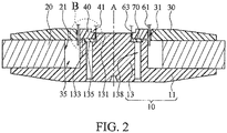
- FIG. 1 is a partially three-dimensional exploded view of a coaxial dual voice coil speaker; and FIG. 2 is a partially cross-sectional view of a coaxial dual voice coil speaker.
- FIG. 3 is an enlarged diagram of an area B in FIG. 2 .
- the coaxial dual voice coil speaker 1 includes a yoke 10, a ring-shaped magnet 20, a first concentrating flux plate 30, a second concentrating flux plate 40, a first voice coil 61, a second voice coil 63, and an isolating ring 70.
- the yoke 10, the ring-shaped magnet 20, the first concentrating flux plate 30, the second concentrating flux plate 40, the first voice coil 61, the second voice coil 63, and the isolating ring 70 have a same central axis A, and are coaxially disposed.
- the first concentrating flux plate 30 and/or the second concentrating flux plate 40 may be made of a magnetic material, which has high magnetic saturation, large magnetic permeability, and low coercivity. Further, the concentrating flux plates may be made of soft magnetic material that has a narrow hysteresis curve and rapidly magnetization and demagnetization.
- the magnetic reluctance of the magnetic material of each of the the concentrating flux plates 30, 40 is much smaller than the magnetic reluctance of the air. Normally, the magnetic permeability of the air is 1, and that of the soft magnetic material is 20,000.
- the concentrating flux plates 30, 40 using the magnetic material described above may have a uniform strong magnetic field in a necessary space, which is the path of the magnetic line and required for the magnetic circuit.
- the concentrating flux plates 30, 40 may be made from low-carbon steel such that the concentrating flux plates have a high saturation of magnetic induction intensity, a high permeability and a low coercivity.
- the high permeability means that the magnetic flux can more readily and easily pass through the concentrating flux plates 30, 40 than through air, and tends to condense the magnetic flux through these parts of the driver.
- the high saturation of magnetic induction intensity means that the concentration flux plates can be used to build a strong magnetic field in and around the voice coils to improve their movement during driving.
- the yoke 10 is a T-shaped yoke, including a base 11 and a column 13.
- the column 13 extends upward from one end of the base 11, and the other end of the column 13 away from the base 11 has a protruding portion 131 and a ring-shaped flange 133.
- the base 11 of the yoke 10 may be plate-shaped, hemispherical, or dish-shaped, and has a column 13 protruding from a center thereof.
- the ring-shaped flange 133 is located at a periphery of the protruding portion 131 and surrounds the protruding portion 131.
- the overall yoke 10 is substantially an inverted T-shaped.
- the ring-shaped magnet 20 includes a first central axial hole 21.
- the column 13 passes through the first central axial hole 21, so that the ring-shaped magnet 20 is sleeved on the yoke 10.
- the ring-shaped magnet 20 comes into contact with the base 11 of the yoke 10.
- the height of the ring-shaped magnet 20 is substantially equal to the height from the base 11 to a top end of the ring-shaped flange 133.
- the first concentrating flux plate 30 includes a first central through hole 31, and the column 13 passes through the first central through hole 31, so that the first concentrating flux plate 30 is disposed on the ring-shaped magnet 20.
- the isolating ring 70 may be an aluminum ring.
- the protruding portion 131 passes through the centre hole of the isolating ring 70, so that the isolating ring 70 is disposed in the ring-shaped groove 135.
- the second concentrating flux plate 40 includes a second central through hole 41, where the second central through hole 41 and the first central through hole 31 also have a same central axis A.
- the protruding portion 131 passes through the second central through hole 41 and abuts against the isolating ring 70. That is, the second concentrating flux plate 40 is sleeved on the column 13 above the isolating ring 70. In other words, the second concentrating flux plate 40 is not directly placed on the yoke 10.
- the first concentrating flux plate 30 has a diameter greater than that of the second concentrating flux plate 40, the second concentrating flux plate 40 is located in a position surrounded by the first central through hole 31 of the first concentrating flux plate 30, and the first concentrating flux plate 30 and the second concentrating flux plate 40 are arranged in a form of a concentric circle.
- first magnetic gap 431 between the second concentrating flux plate 40 and the first concentrating flux plate 30, and there is a second magnetic gap 433 between the second concentrating flux plate 40 and the protruding portion 131.
- the height of the isolating ring 70 is higher than that of the ring-shaped flange 133, so that there is a separating part 137 between the second concentrating flux plate 40 and the ring-shaped flange 133.
- the first concentrating flux plate 30 and the second concentrating flux plate 40 are substantially located at a same height, when viewed along the axis A.
- the first voice coil 61 is located in the first magnetic gap 431, and the second voice coil 63 is located in the second magnetic gap 433.
- the first voice coil 61 and the second voice coil 63 may be fixed by using a holder and can be connected to a diaphragm, so that when the first voice coil 61 and the second voice coil 63 receive signals, the first voice coil 61 and the second voice coil 63 interact with a magnetic force of the ring-shaped magnet 20, to drive the diaphragm vibrating and make a sound.
- the radius of the first voice coil 61 is greater than that of the second voice coil 63.
- the first voice coil 61 may be a bass voice coil, which generates a low frequency sound when driving the diaphragm to vibrate.
- the second voice coil 63 may be a treble voice coil, which generates a high frequency sound when driving the diaphragm to vibrate.
- the first voice coil 61 and the second voice coil 63 may each be connected to a diaphragm, or may be connected to a same diaphragm.
- the first voice coil 61 is connected to an outer edge area of the diaphragm (not shown), and the second voice coil 63 is connected to a central area of the diaphragm. Although a channel is not shown in the yoke 10 in FIG. 1 . Referring to FIG.
- the column 13 may further include two channels 138 through which leading lines (not shown) of the voice coils can pass, so that impact caused by a touch of other components to the voice coils is avoided.
- the channels 138 can further improve heat dissipation effects.
- the radius of the ring-shaped magnet 20 may be adjusted, and intensity of magnetic lines in the first magnetic gap 431, the second magnetic gap 433, or the separating part 137 between the second concentrating flux plate 40 and the ring-shaped flange 133 may be further adjusted.
- a buffer material such as sound-absorbing cotton may further be filled in the separating space 35, to avoid impact caused by vibration of the coaxial dual voice coil speaker 1.
- the base 11 of the yoke 10 has a thickness gradually decreasing from an area close to the protruding portion 13 to a periphery.
- the shape of the base 11 is not limited in this application, and may also be adjusted in combination with the shape of an overall horn cavity.
- the first concentrating flux plate 30 has a thickness gradually decreasing from an area close to the first central through hole 31 to a periphery. In this way, the first concentrating flux plate 30 and the base 11 of the yoke 10 may present a vertically symmetrical change in thicknesses, so that the overall structure is dish-shaped, and the overall size is further reduced.
- FIG. 4 is a diagram of distribution of magnetic lines of a coaxial dual voice coil speaker.
- the magnetic lines may be radiated out from one end (a top end) of the ring-shaped magnet 20 to the other end (a bottom end), pass through the base 11 of the yoke 10 and reach the column 13 of the yoke 10, and then go back to the ring-shaped magnet 20 (a top end) sequentially through the second magnetic gap 433, the second concentrating flux plate 40, the first magnetic gap 431, and the first concentrating flux plate 30.
- most magnetic lines are radiated out from the protruding portion 131 of the yoke 10 passing through the second magnetic gap 433 (i.e.
- the magnetic lines go back to the ring-shaped magnet 20 from the first concentrating flux plate 30.
- the second magnetic gap 433 is located between the protruding portion 131 and the second concentrating flux plate 40, and the first magnetic gap 431 is located between the first concentrating flux plate 30 and the second concentrating flux plate 40.
- the widths of the first magnetic gap 431 and the second magnetic gap 433 are adjustable, the density of the magnetic lines between the first magnetic gap 431 and the second magnetic gap 433 can be adjusted, so that an interaction effect between a magnetic force generated by the ring-shaped magnet 20, and the first voice coil 61 and the second voice coil 63 after a signal is received is indirectly adjusted, and a frequency response of the coaxial dual voice coil speaker 1 is further adjustable.
- the second concentrating flux plate 40 further includes a step portion 45.
- the step portion 45 is neighboring to the second central through hole 41, and the step portion 45 close to the first magnetic gap 431 is relatively higher than at the second magnetic gap 433. Based on this structure, the magnetic lines can better centrally enter the second magnetic gap 433.
- some magnetic lines pass by entering the first magnetic gap 431 through the ring-shaped flange 133 of the yoke 10 and the separating part 137, and then going back to the ring-shaped magnet 20 through the concentrating flux plate 30.
- the density of the magnetic lines in the first magnetic gap 431 may be increased by using the ring-shaped flange 133, so that an interaction effect of a magnetic force after the first voice coil 61 receives a signal is enhanced, and a relatively large bass resonance effect is achieved.
- the isolating ring 70 is made of a nonpermeable material and is, for example, an aluminum ring. Because the isolating ring 70 is made of a high magnetoresistant nonpermeable material, only a few magnetic lines pass through the isolating ring 70. In one embodiment, the width of the isolating ring 70 is greater than the width of the ring-shaped flange 133. Therefore, the density of magnetic lines passing through the second magnetic gap 433 may be adjusted by adjusting the width of the ring-shaped flange 133, the height and the width of the isolating ring 70, and the width or the height of the separating part 137.
- a density ratio of magnetic lines between the first magnetic gap 431 and the second magnetic gap 433 can be adjusted by adjusting a distance between the first concentrating flux plate 30 and the second concentrating flux plate 40, a distance between the protruding portion 131 and the second concentrating flux plate 40, and the widths and heights of the ring-shaped flange 133 and the isolating ring 70, and a required frequency response can further satisfied according to customized requirements.
- the coaxial dual voice coil speaker 1 can be driven independently in high frequency and low frequency bands by using the first voice coil 61 and the second voice coil 63, and achieve a better sound parsing effect in the high frequency and low frequency parts.
- the coaxial dual voice coil speaker 1 can further achieve an effect of light weight, simple structure, and rapidness in assembling by reducing overall components by using a design in which the yoke 10 is shared.
- the density of magnetic lines can be adjusted by adjusting a distance between the first concentrating flux plate 30 and the second concentrating flux plate 40, a distance between the protruding portion 131 and the second concentrating flux plate 40, and the widths and heights of the ring-shaped flange 133 and the isolating ring 70, and a required frequency response can further be satisfied according to customized requirements.
Landscapes
- Physics & Mathematics (AREA)
- Engineering & Computer Science (AREA)
- Acoustics & Sound (AREA)
- Signal Processing (AREA)
- Audible-Bandwidth Dynamoelectric Transducers Other Than Pickups (AREA)
Claims (14)
- Haut-parleur comprenant :un étrier (10) comprenant une base (11) et une colonne (13), dans lequel la colonne (13) s'étend depuis une extrémité de la base (11), l'autre extrémité de la colonne éloignée de la base a une portion en projection (131) et une bride de forme annulaire (133), la bride de forme annulaire (133) entoure la portion en projection (131), et une gorge de forme annulaire (135) est située entre la bride de forme annulaire (133) et la portion en projection (131) ;un aimant de forme annulaire (20) comprenant un premier trou axial central (21), dans lequel la colonne (13) passe à travers le premier trou axial central (21), de sorte que l'aimant de forme annulaire (20) est manchonné sur l'étrier (10) ;une première plaque à flux (30) comprenant un premier trou traversant central (31), dans lequel la colonne (13) passe à travers le premier trou traversant central (31), de sorte que la première plaque à flux (30) est disposée sur l'aimant de forme annulaire (20) ;une bague isolante (70), dans lequel la portion en projection (131) passe à travers la bague isolante (70), de sorte que la bague isolante (70) est disposée dans la gorge de forme annulaire (135) ;une seconde plaque à flux (40) comprenant un second trou traversant central (41), dans lequel le second trou traversant central (41) et le premier trou traversant central (31) ont un même axe central, la portion en projection (131) passe à travers le second trou traversant central (41), la seconde plaque à flux de concentration (40) est disposée sur la bague isolante (70), un premier entrefer magnétique (431) est situé entre la seconde plaque à flux (40) et la première plaque à flux (30), et un second entrefer magnétique (433) est situé entre la seconde plaque à flux (40) et la portion en projection (131) ;une première bobine acoustique (61) située dans le premier entrefer magnétique (431) ; etune seconde bobine acoustique (63) située dans le second entrefer magnétique (433).
- Haut-parleur selon la revendication 1, dans lequel
la bague isolante est une bague en aluminium, la hauteur de la bague isolante est plus élevée que celle de la bride de forme annulaire, la hauteur de la portion en projection est plus élevée que celle de la bride de forme annulaire, et une pièce de séparation est située entre la seconde plaque à flux et la bride de forme annulaire. - Haut-parleur selon l'une ou l'autre des revendications 1 ou 2, dans lequel
la première plaque à flux et la seconde plaque à flux sont situées sensiblement à une même hauteur horizontale. - Haut-parleur selon l'une quelconque des revendications précédentes, dans lequel
le diamètre du premier trou axial central est plus grand que le diamètre de la colonne, de sorte qu'un espace de séparation est formé entre l'aimant de forme annulaire et la colonne. - Haut-parleur selon l'une quelconque des revendications précédentes, dans lequel
la base a une épaisseur qui diminue progressivement depuis une zone proche de la portion en projection jusqu'à une périphérie. - Haut-parleur selon l'une quelconque des revendications précédentes, dans lequel
la première plaque à flux a une épaisseur qui diminue progressivement depuis une zone proche du premier trou traversant central jusqu'à une périphérie. - Haut-parleur selon l'une quelconque des revendications précédentes, dans lequel
la seconde plaque à flux comprend en outre une portion en gradin, et la portion en gradin est au voisinage du second trou traversant central. - Haut-parleur selon l'une quelconque des revendications précédentes, dans lequel
la première bobine acoustique est une bobine acoustique pour les basses, et la seconde bobine acoustique est une bobine acoustique pour les aigus. - Haut-parleur selon l'une quelconque des revendications précédentes, dans lequel
la largeur de la bague isolante est plus grande que la largeur de la bride de forme annulaire. - Haut-parleur selon l'une quelconque des revendications précédentes, dans lequel
la hauteur de l'aimant de forme annulaire est sensiblement égale à la hauteur depuis la base jusqu'à une extrémité au sommet de la bride de forme annulaire. - Haut-parleur selon l'une quelconque des revendications précédentes, dans lequel le haut-parleur est un haut-parleur à double bobine acoustique coaxiale.
- Haut-parleur selon l'une quelconque des revendications précédentes, dans lequel la première et la seconde plaque à flux sont chacune des plaques à flux de concentration.
- Haut-parleur selon l'une quelconque des revendications précédentes, dans lequel la première et la seconde plaque à flux comprennent un matériau magnétique, qui présente une forte saturation magnétique, une forte perméabilité magnétique, et une faible coercivité.
- Haut-parleur selon l'une quelconque des revendications précédentes, dans lequel la première et la seconde plaque à flux sont réalisées en matériau magnétique doux qui présente une courbe d'hystérésis étroite et une magnétisation et démagnétisation rapides, par exemple un acier à faible carbone.
Applications Claiming Priority (1)
| Application Number | Priority Date | Filing Date | Title |
|---|---|---|---|
| US201762550362P | 2017-08-25 | 2017-08-25 |
Publications (2)
| Publication Number | Publication Date |
|---|---|
| EP3448061A1 EP3448061A1 (fr) | 2019-02-27 |
| EP3448061B1 true EP3448061B1 (fr) | 2019-11-13 |
Family
ID=63405071
Family Applications (1)
| Application Number | Title | Priority Date | Filing Date |
|---|---|---|---|
| EP18190740.3A Active EP3448061B1 (fr) | 2017-08-25 | 2018-08-24 | Haut-parleur coaxial à double bobine acoustique |
Country Status (2)
| Country | Link |
|---|---|
| EP (1) | EP3448061B1 (fr) |
| CN (2) | CN208754543U (fr) |
Families Citing this family (6)
| Publication number | Priority date | Publication date | Assignee | Title |
|---|---|---|---|---|
| EP3448061B1 (fr) * | 2017-08-25 | 2019-11-13 | Tymphany HK Limited | Haut-parleur coaxial à double bobine acoustique |
| CN121357448A (zh) * | 2021-10-11 | 2026-01-16 | 中科声特美(苏州)声学科技有限公司 | 一种受话器和一种电子设备 |
| CN217721457U (zh) * | 2022-06-30 | 2022-11-01 | 瑞声光电科技(常州)有限公司 | 同轴扬声器 |
| CN218387875U (zh) * | 2022-08-30 | 2023-01-24 | 瑞声光电科技(常州)有限公司 | 一种同轴扬声器 |
| CN116233701A (zh) * | 2023-01-10 | 2023-06-06 | 深圳立讯电声科技有限公司 | 通气轭铁、磁路系统及双面扬声器 |
| CN116528130A (zh) * | 2023-05-31 | 2023-08-01 | 潍坊歌尔丹拿电子科技有限公司 | 发声装置和终端设备 |
Family Cites Families (10)
| Publication number | Priority date | Publication date | Assignee | Title |
|---|---|---|---|---|
| CN1121809C (zh) * | 1999-04-09 | 2003-09-17 | 张凡 | 扬声器 |
| CN201657285U (zh) * | 2010-01-11 | 2010-11-24 | 瑞声声学科技(深圳)有限公司 | 微型双磁钢双音圈电磁扬声器 |
| US9154883B2 (en) * | 2011-09-06 | 2015-10-06 | Apple Inc. | Low rise speaker assembly having a dual voice coil driver |
| HU230260B1 (hu) * | 2012-09-17 | 2015-11-30 | NOVINEX Innováció- és Kutatás-hasznosító Iroda Kft. | Koaxiális hangszóró elrendezés |
| GB2502189B (en) * | 2013-03-25 | 2014-06-04 | Tannoy Ltd | Loudspeaker |
| CN103281655A (zh) * | 2013-04-16 | 2013-09-04 | 沙文金 | 一种双音圈动圈式扬声器 |
| US9100733B2 (en) * | 2013-06-05 | 2015-08-04 | Harman International Industries, Inc. | Multi-way coaxial loudspeaker with internal magnet motor and permanent magnet cylinder |
| US9173035B2 (en) * | 2013-11-07 | 2015-10-27 | Harman International Industries, Incorporated | Dual coil moving magnet transducer |
| CN105848064B (zh) * | 2016-05-10 | 2019-06-04 | 青岛歌尔声学科技有限公司 | 双磁隙磁路系统和具有该双磁隙磁路系统的扬声器 |
| EP3448061B1 (fr) * | 2017-08-25 | 2019-11-13 | Tymphany HK Limited | Haut-parleur coaxial à double bobine acoustique |
-
2018
- 2018-08-24 EP EP18190740.3A patent/EP3448061B1/fr active Active
- 2018-08-24 CN CN201821382532.6U patent/CN208754543U/zh not_active Withdrawn - After Issue
- 2018-08-24 CN CN201810971987.XA patent/CN109429151B/zh active Active
Non-Patent Citations (1)
| Title |
|---|
| None * |
Also Published As
| Publication number | Publication date |
|---|---|
| CN109429151A (zh) | 2019-03-05 |
| CN109429151B (zh) | 2023-12-01 |
| EP3448061A1 (fr) | 2019-02-27 |
| CN208754543U (zh) | 2019-04-16 |
Similar Documents
| Publication | Publication Date | Title |
|---|---|---|
| EP3448061B1 (fr) | Haut-parleur coaxial à double bobine acoustique | |
| US8135162B2 (en) | Multiple magnet loudspeaker | |
| US7724915B2 (en) | Speaker device | |
| US8649550B2 (en) | Multi-magnet system and speaker using same | |
| US8891809B2 (en) | Split magnet loudspeaker | |
| EP3448062B1 (fr) | Moteur de haut-parleur coaxial à double bobine | |
| US9271071B2 (en) | Loudspeaker | |
| US8611583B2 (en) | Compact coaxial crossover-free loudspeaker | |
| CN117241180A (zh) | 扬声器 | |
| US9282410B2 (en) | Transducer motor structure with enhanced flux | |
| JPH10304493A (ja) | 電気−音響変換装置及び音響−電気変換装置 | |
| JP2019047464A (ja) | スピーカシステム | |
| JP2006279797A (ja) | 動電型スピーカー | |
| CN102036150A (zh) | 复合式同轴扬声器 | |
| KR20040069394A (ko) | 일체형 투웨이 스피커 | |
| JPS6028400A (ja) | ダイナミツク形スピ−カ | |
| KR102658276B1 (ko) | 자성체 진동판을 이용한 평판형 트위터 스피커 | |
| JP2020031405A (ja) | スピーカシステム | |
| JP2003169393A (ja) | スピーカ | |
| KR102044941B1 (ko) | 중저음 발생용 음향발생부를 구비한 패널 가진형 스피커 | |
| JPH11298995A (ja) | 同軸型スピーカ | |
| JP2009171186A (ja) | スピーカ | |
| CN121126215A (zh) | 扬声器磁路结构、扬声器及音响设备 | |
| JPH04329800A (ja) | ホーン形ドライバー | |
| KR20090120161A (ko) | 콘스피커의 구조 |
Legal Events
| Date | Code | Title | Description |
|---|---|---|---|
| PUAI | Public reference made under article 153(3) epc to a published international application that has entered the european phase |
Free format text: ORIGINAL CODE: 0009012 |
|
| STAA | Information on the status of an ep patent application or granted ep patent |
Free format text: STATUS: REQUEST FOR EXAMINATION WAS MADE |
|
| 17P | Request for examination filed |
Effective date: 20180824 |
|
| AK | Designated contracting states |
Kind code of ref document: A1 Designated state(s): AL AT BE BG CH CY CZ DE DK EE ES FI FR GB GR HR HU IE IS IT LI LT LU LV MC MK MT NL NO PL PT RO RS SE SI SK SM TR |
|
| AX | Request for extension of the european patent |
Extension state: BA ME |
|
| RBV | Designated contracting states (corrected) |
Designated state(s): AL AT BE BG CH CY CZ DE DK EE ES FI FR GB GR HR HU IE IS IT LI LT LU LV MC MK MT NL NO PL PT RO RS SE SI SK SM TR |
|
| GRAP | Despatch of communication of intention to grant a patent |
Free format text: ORIGINAL CODE: EPIDOSNIGR1 |
|
| STAA | Information on the status of an ep patent application or granted ep patent |
Free format text: STATUS: GRANT OF PATENT IS INTENDED |
|
| RIC1 | Information provided on ipc code assigned before grant |
Ipc: H04R 9/06 20060101ALI20190715BHEP Ipc: H04R 9/02 20060101AFI20190715BHEP Ipc: H04R 1/24 20060101ALN20190715BHEP |
|
| INTG | Intention to grant announced |
Effective date: 20190819 |
|
| RIN1 | Information on inventor provided before grant (corrected) |
Inventor name: YANG, SHAO LIN Inventor name: ZHAN, YU BING |
|
| GRAS | Grant fee paid |
Free format text: ORIGINAL CODE: EPIDOSNIGR3 |
|
| GRAA | (expected) grant |
Free format text: ORIGINAL CODE: 0009210 |
|
| STAA | Information on the status of an ep patent application or granted ep patent |
Free format text: STATUS: THE PATENT HAS BEEN GRANTED |
|
| AK | Designated contracting states |
Kind code of ref document: B1 Designated state(s): AL AT BE BG CH CY CZ DE DK EE ES FI FR GB GR HR HU IE IS IT LI LT LU LV MC MK MT NL NO PL PT RO RS SE SI SK SM TR |
|
| REG | Reference to a national code |
Ref country code: CH Ref legal event code: EP Ref country code: AT Ref legal event code: REF Ref document number: 1202941 Country of ref document: AT Kind code of ref document: T Effective date: 20191115 |
|
| REG | Reference to a national code |
Ref country code: DE Ref legal event code: R096 Ref document number: 602018001177 Country of ref document: DE |
|
| REG | Reference to a national code |
Ref country code: IE Ref legal event code: FG4D |
|
| REG | Reference to a national code |
Ref country code: NL Ref legal event code: MP Effective date: 20191113 |
|
| REG | Reference to a national code |
Ref country code: LT Ref legal event code: MG4D |
|
| PG25 | Lapsed in a contracting state [announced via postgrant information from national office to epo] |
Ref country code: PL Free format text: LAPSE BECAUSE OF FAILURE TO SUBMIT A TRANSLATION OF THE DESCRIPTION OR TO PAY THE FEE WITHIN THE PRESCRIBED TIME-LIMIT Effective date: 20191113 Ref country code: PT Free format text: LAPSE BECAUSE OF FAILURE TO SUBMIT A TRANSLATION OF THE DESCRIPTION OR TO PAY THE FEE WITHIN THE PRESCRIBED TIME-LIMIT Effective date: 20200313 Ref country code: LV Free format text: LAPSE BECAUSE OF FAILURE TO SUBMIT A TRANSLATION OF THE DESCRIPTION OR TO PAY THE FEE WITHIN THE PRESCRIBED TIME-LIMIT Effective date: 20191113 Ref country code: SE Free format text: LAPSE BECAUSE OF FAILURE TO SUBMIT A TRANSLATION OF THE DESCRIPTION OR TO PAY THE FEE WITHIN THE PRESCRIBED TIME-LIMIT Effective date: 20191113 Ref country code: FI Free format text: LAPSE BECAUSE OF FAILURE TO SUBMIT A TRANSLATION OF THE DESCRIPTION OR TO PAY THE FEE WITHIN THE PRESCRIBED TIME-LIMIT Effective date: 20191113 Ref country code: BG Free format text: LAPSE BECAUSE OF FAILURE TO SUBMIT A TRANSLATION OF THE DESCRIPTION OR TO PAY THE FEE WITHIN THE PRESCRIBED TIME-LIMIT Effective date: 20200213 Ref country code: GR Free format text: LAPSE BECAUSE OF FAILURE TO SUBMIT A TRANSLATION OF THE DESCRIPTION OR TO PAY THE FEE WITHIN THE PRESCRIBED TIME-LIMIT Effective date: 20200214 Ref country code: NO Free format text: LAPSE BECAUSE OF FAILURE TO SUBMIT A TRANSLATION OF THE DESCRIPTION OR TO PAY THE FEE WITHIN THE PRESCRIBED TIME-LIMIT Effective date: 20200213 Ref country code: LT Free format text: LAPSE BECAUSE OF FAILURE TO SUBMIT A TRANSLATION OF THE DESCRIPTION OR TO PAY THE FEE WITHIN THE PRESCRIBED TIME-LIMIT Effective date: 20191113 Ref country code: NL Free format text: LAPSE BECAUSE OF FAILURE TO SUBMIT A TRANSLATION OF THE DESCRIPTION OR TO PAY THE FEE WITHIN THE PRESCRIBED TIME-LIMIT Effective date: 20191113 |
|
| PG25 | Lapsed in a contracting state [announced via postgrant information from national office to epo] |
Ref country code: HR Free format text: LAPSE BECAUSE OF FAILURE TO SUBMIT A TRANSLATION OF THE DESCRIPTION OR TO PAY THE FEE WITHIN THE PRESCRIBED TIME-LIMIT Effective date: 20191113 Ref country code: IS Free format text: LAPSE BECAUSE OF FAILURE TO SUBMIT A TRANSLATION OF THE DESCRIPTION OR TO PAY THE FEE WITHIN THE PRESCRIBED TIME-LIMIT Effective date: 20200313 Ref country code: RS Free format text: LAPSE BECAUSE OF FAILURE TO SUBMIT A TRANSLATION OF THE DESCRIPTION OR TO PAY THE FEE WITHIN THE PRESCRIBED TIME-LIMIT Effective date: 20191113 |
|
| PG25 | Lapsed in a contracting state [announced via postgrant information from national office to epo] |
Ref country code: AL Free format text: LAPSE BECAUSE OF FAILURE TO SUBMIT A TRANSLATION OF THE DESCRIPTION OR TO PAY THE FEE WITHIN THE PRESCRIBED TIME-LIMIT Effective date: 20191113 |
|
| PG25 | Lapsed in a contracting state [announced via postgrant information from national office to epo] |
Ref country code: RO Free format text: LAPSE BECAUSE OF FAILURE TO SUBMIT A TRANSLATION OF THE DESCRIPTION OR TO PAY THE FEE WITHIN THE PRESCRIBED TIME-LIMIT Effective date: 20191113 Ref country code: CZ Free format text: LAPSE BECAUSE OF FAILURE TO SUBMIT A TRANSLATION OF THE DESCRIPTION OR TO PAY THE FEE WITHIN THE PRESCRIBED TIME-LIMIT Effective date: 20191113 Ref country code: EE Free format text: LAPSE BECAUSE OF FAILURE TO SUBMIT A TRANSLATION OF THE DESCRIPTION OR TO PAY THE FEE WITHIN THE PRESCRIBED TIME-LIMIT Effective date: 20191113 Ref country code: ES Free format text: LAPSE BECAUSE OF FAILURE TO SUBMIT A TRANSLATION OF THE DESCRIPTION OR TO PAY THE FEE WITHIN THE PRESCRIBED TIME-LIMIT Effective date: 20191113 Ref country code: DK Free format text: LAPSE BECAUSE OF FAILURE TO SUBMIT A TRANSLATION OF THE DESCRIPTION OR TO PAY THE FEE WITHIN THE PRESCRIBED TIME-LIMIT Effective date: 20191113 |
|
| REG | Reference to a national code |
Ref country code: DE Ref legal event code: R097 Ref document number: 602018001177 Country of ref document: DE |
|
| REG | Reference to a national code |
Ref country code: AT Ref legal event code: MK05 Ref document number: 1202941 Country of ref document: AT Kind code of ref document: T Effective date: 20191113 |
|
| PG25 | Lapsed in a contracting state [announced via postgrant information from national office to epo] |
Ref country code: SK Free format text: LAPSE BECAUSE OF FAILURE TO SUBMIT A TRANSLATION OF THE DESCRIPTION OR TO PAY THE FEE WITHIN THE PRESCRIBED TIME-LIMIT Effective date: 20191113 Ref country code: SM Free format text: LAPSE BECAUSE OF FAILURE TO SUBMIT A TRANSLATION OF THE DESCRIPTION OR TO PAY THE FEE WITHIN THE PRESCRIBED TIME-LIMIT Effective date: 20191113 |
|
| PLBE | No opposition filed within time limit |
Free format text: ORIGINAL CODE: 0009261 |
|
| STAA | Information on the status of an ep patent application or granted ep patent |
Free format text: STATUS: NO OPPOSITION FILED WITHIN TIME LIMIT |
|
| 26N | No opposition filed |
Effective date: 20200814 |
|
| PG25 | Lapsed in a contracting state [announced via postgrant information from national office to epo] |
Ref country code: AT Free format text: LAPSE BECAUSE OF FAILURE TO SUBMIT A TRANSLATION OF THE DESCRIPTION OR TO PAY THE FEE WITHIN THE PRESCRIBED TIME-LIMIT Effective date: 20191113 Ref country code: SI Free format text: LAPSE BECAUSE OF FAILURE TO SUBMIT A TRANSLATION OF THE DESCRIPTION OR TO PAY THE FEE WITHIN THE PRESCRIBED TIME-LIMIT Effective date: 20191113 |
|
| PG25 | Lapsed in a contracting state [announced via postgrant information from national office to epo] |
Ref country code: IT Free format text: LAPSE BECAUSE OF FAILURE TO SUBMIT A TRANSLATION OF THE DESCRIPTION OR TO PAY THE FEE WITHIN THE PRESCRIBED TIME-LIMIT Effective date: 20191113 |
|
| PG25 | Lapsed in a contracting state [announced via postgrant information from national office to epo] |
Ref country code: MC Free format text: LAPSE BECAUSE OF FAILURE TO SUBMIT A TRANSLATION OF THE DESCRIPTION OR TO PAY THE FEE WITHIN THE PRESCRIBED TIME-LIMIT Effective date: 20191113 |
|
| PG25 | Lapsed in a contracting state [announced via postgrant information from national office to epo] |
Ref country code: LU Free format text: LAPSE BECAUSE OF NON-PAYMENT OF DUE FEES Effective date: 20200824 |
|
| REG | Reference to a national code |
Ref country code: BE Ref legal event code: MM Effective date: 20200831 |
|
| PG25 | Lapsed in a contracting state [announced via postgrant information from national office to epo] |
Ref country code: FR Free format text: LAPSE BECAUSE OF NON-PAYMENT OF DUE FEES Effective date: 20200831 |
|
| PG25 | Lapsed in a contracting state [announced via postgrant information from national office to epo] |
Ref country code: IE Free format text: LAPSE BECAUSE OF NON-PAYMENT OF DUE FEES Effective date: 20200824 Ref country code: BE Free format text: LAPSE BECAUSE OF NON-PAYMENT OF DUE FEES Effective date: 20200831 |
|
| REG | Reference to a national code |
Ref country code: CH Ref legal event code: PL |
|
| PG25 | Lapsed in a contracting state [announced via postgrant information from national office to epo] |
Ref country code: LI Free format text: LAPSE BECAUSE OF NON-PAYMENT OF DUE FEES Effective date: 20210831 Ref country code: CH Free format text: LAPSE BECAUSE OF NON-PAYMENT OF DUE FEES Effective date: 20210831 |
|
| PG25 | Lapsed in a contracting state [announced via postgrant information from national office to epo] |
Ref country code: TR Free format text: LAPSE BECAUSE OF FAILURE TO SUBMIT A TRANSLATION OF THE DESCRIPTION OR TO PAY THE FEE WITHIN THE PRESCRIBED TIME-LIMIT Effective date: 20191113 Ref country code: MT Free format text: LAPSE BECAUSE OF FAILURE TO SUBMIT A TRANSLATION OF THE DESCRIPTION OR TO PAY THE FEE WITHIN THE PRESCRIBED TIME-LIMIT Effective date: 20191113 Ref country code: CY Free format text: LAPSE BECAUSE OF FAILURE TO SUBMIT A TRANSLATION OF THE DESCRIPTION OR TO PAY THE FEE WITHIN THE PRESCRIBED TIME-LIMIT Effective date: 20191113 |
|
| PG25 | Lapsed in a contracting state [announced via postgrant information from national office to epo] |
Ref country code: MK Free format text: LAPSE BECAUSE OF FAILURE TO SUBMIT A TRANSLATION OF THE DESCRIPTION OR TO PAY THE FEE WITHIN THE PRESCRIBED TIME-LIMIT Effective date: 20191113 |
|
| PGFP | Annual fee paid to national office [announced via postgrant information from national office to epo] |
Ref country code: DE Payment date: 20220630 Year of fee payment: 5 |
|
| GBPC | Gb: european patent ceased through non-payment of renewal fee |
Effective date: 20220824 |
|
| PG25 | Lapsed in a contracting state [announced via postgrant information from national office to epo] |
Ref country code: GB Free format text: LAPSE BECAUSE OF NON-PAYMENT OF DUE FEES Effective date: 20220824 |
|
| REG | Reference to a national code |
Ref country code: DE Ref legal event code: R119 Ref document number: 602018001177 Country of ref document: DE |
|
| PG25 | Lapsed in a contracting state [announced via postgrant information from national office to epo] |
Ref country code: DE Free format text: LAPSE BECAUSE OF NON-PAYMENT OF DUE FEES Effective date: 20240301 |