EP3448093B1 - System und verfahren zur vorhersage der sendeleistung in einem drahtloskommunikationssystem - Google Patents
System und verfahren zur vorhersage der sendeleistung in einem drahtloskommunikationssystem Download PDFInfo
- Publication number
- EP3448093B1 EP3448093B1 EP17187415.9A EP17187415A EP3448093B1 EP 3448093 B1 EP3448093 B1 EP 3448093B1 EP 17187415 A EP17187415 A EP 17187415A EP 3448093 B1 EP3448093 B1 EP 3448093B1
- Authority
- EP
- European Patent Office
- Prior art keywords
- signal
- map
- computer
- value
- reliability coefficient
- Prior art date
- Legal status (The legal status is an assumption and is not a legal conclusion. Google has not performed a legal analysis and makes no representation as to the accuracy of the status listed.)
- Active
Links
Images


Classifications
-
- H—ELECTRICITY
- H04—ELECTRIC COMMUNICATION TECHNIQUE
- H04W—WIRELESS COMMUNICATION NETWORKS
- H04W52/00—Power management, e.g. Transmission Power Control [TPC] or power classes
- H04W52/04—Transmission power control [TPC]
- H04W52/18—TPC being performed according to specific parameters
- H04W52/22—TPC being performed according to specific parameters taking into account previous information or commands
- H04W52/223—TPC being performed according to specific parameters taking into account previous information or commands predicting future states of the transmission
-
- H—ELECTRICITY
- H04—ELECTRIC COMMUNICATION TECHNIQUE
- H04W—WIRELESS COMMUNICATION NETWORKS
- H04W52/00—Power management, e.g. Transmission Power Control [TPC] or power classes
- H04W52/04—Transmission power control [TPC]
- H04W52/06—TPC algorithms
- H04W52/14—Separate analysis of uplink or downlink
- H04W52/146—Uplink power control
-
- H—ELECTRICITY
- H04—ELECTRIC COMMUNICATION TECHNIQUE
- H04W—WIRELESS COMMUNICATION NETWORKS
- H04W52/00—Power management, e.g. Transmission Power Control [TPC] or power classes
- H04W52/04—Transmission power control [TPC]
- H04W52/18—TPC being performed according to specific parameters
- H04W52/28—TPC being performed according to specific parameters using user profile, e.g. mobile speed, priority or network state, e.g. standby, idle or non-transmission
- H04W52/283—Power depending on the position of the mobile
-
- H—ELECTRICITY
- H04—ELECTRIC COMMUNICATION TECHNIQUE
- H04W—WIRELESS COMMUNICATION NETWORKS
- H04W52/00—Power management, e.g. Transmission Power Control [TPC] or power classes
- H04W52/04—Transmission power control [TPC]
- H04W52/18—TPC being performed according to specific parameters
- H04W52/22—TPC being performed according to specific parameters taking into account previous information or commands
- H04W52/226—TPC being performed according to specific parameters taking into account previous information or commands using past references to control power, e.g. look-up-table
-
- H—ELECTRICITY
- H04—ELECTRIC COMMUNICATION TECHNIQUE
- H04W—WIRELESS COMMUNICATION NETWORKS
- H04W52/00—Power management, e.g. Transmission Power Control [TPC] or power classes
- H04W52/04—Transmission power control [TPC]
- H04W52/18—TPC being performed according to specific parameters
- H04W52/24—TPC being performed according to specific parameters using SIR [Signal to Interference Ratio] or other wireless path parameters
- H04W52/245—TPC being performed according to specific parameters using SIR [Signal to Interference Ratio] or other wireless path parameters taking into account received signal strength
-
- H—ELECTRICITY
- H04—ELECTRIC COMMUNICATION TECHNIQUE
- H04W—WIRELESS COMMUNICATION NETWORKS
- H04W52/00—Power management, e.g. Transmission Power Control [TPC] or power classes
- H04W52/04—Transmission power control [TPC]
- H04W52/18—TPC being performed according to specific parameters
- H04W52/26—TPC being performed according to specific parameters using transmission rate or quality of service QoS [Quality of Service]
- H04W52/267—TPC being performed according to specific parameters using transmission rate or quality of service QoS [Quality of Service] taking into account the information rate
-
- H—ELECTRICITY
- H04—ELECTRIC COMMUNICATION TECHNIQUE
- H04W—WIRELESS COMMUNICATION NETWORKS
- H04W52/00—Power management, e.g. Transmission Power Control [TPC] or power classes
- H04W52/04—Transmission power control [TPC]
- H04W52/18—TPC being performed according to specific parameters
- H04W52/28—TPC being performed according to specific parameters using user profile, e.g. mobile speed, priority or network state, e.g. standby, idle or non-transmission
- H04W52/285—TPC being performed according to specific parameters using user profile, e.g. mobile speed, priority or network state, e.g. standby, idle or non-transmission taking into account the mobility of the user
-
- H—ELECTRICITY
- H04—ELECTRIC COMMUNICATION TECHNIQUE
- H04W—WIRELESS COMMUNICATION NETWORKS
- H04W84/00—Network topologies
- H04W84/02—Hierarchically pre-organised networks, e.g. paging networks, cellular networks, WLAN [Wireless Local Area Network] or WLL [Wireless Local Loop]
- H04W84/10—Small scale networks; Flat hierarchical networks
- H04W84/12—WLAN [Wireless Local Area Networks]
Definitions
- the present invention relates to a system and method for prediction of transmission power in a wireless communication system.
- the present invention relates to wireless communication systems e.g. Wi-Fi or Bluetooth or the like and to such systems that require one or more of the devices to be mobile.
- duration of operation on battery power is a key factor.
- optimisation of the use of power is a significant aspect.
- the present invention aims at reduction of power consumption via adaptive changes of antenna transmission power.
- EP 2171873 A1 discloses a method of monitoring the parameters of the device's own antenna in order to keep as close to the maximum limit of antenna power as possible without exceeding that power.
- EP 1122892 A2 discloses a method of monitoring the parameters of the devices own antenna in order to influence the times between monitoring events and adjustment of antenna power.
- US 20080166973 A1 discloses a method for adjusting a radio-frequency coverage map.
- the method includes receiving calibration data comprising observed received signal strength values at one or more calibration points corresponding to a radio frequency transmitter, and identifying an applicable coverage map, where the coverage map provides, for the radio frequency transmitter, estimated received signal strength values at one or more locations.
- a transmission power management unit may store a table representing correspondences between RSSI and transmission power, and acquire, from the table, the value of transmission power that corresponds to the received RSSI, or alternatively, may calculate the value of transmission power by using a formula provided for obtaining the transmission power from the RSSI. Then, from the correlation information on the transmission power and the SAR, the transmission power management unit 3 acquires an SAR value that corresponds to the predicted value of the transmission power for the stopped communication.
- US 20070191047 A1 discloses a method and apparatus for processing transmit power control (TPC) commands in a wideband CDMA (WCDMA) network based on a sign metric are disclosed and may include calculating a sign metric of a downlink dedicated physical channel (DPCH) based on a plurality of TPC bits received via the downlink DPCH. A value of at least one of the plurality of TPC bits may not be known when the at least one of the plurality of TPC bits is received.
- the sign metric may specify an error associated with the plurality of TPC bits.
- Transmit power may be adjusted for a signal transmitted via at least one uplink communication channel based on the calculated sign metric.
- At least one reliability weight value may be calculated for at least a portion of the received TCP bits, based on the calculated sign metric.
- the present invention defines a method to achieve this goal.
- An object of the present invention is a system and method for prediction of transmission power in a wireless communication system, according to the appended claims.
- these quantities take the form of electrical or magnetic signals capable of being stored, transferred, combined, compared, and otherwise manipulated in a computer system.
- these signals are referred to as bits, packets, messages, values, elements, symbols, characters, terms, numbers, or the like.
- a computer-readable (storage) medium typically may be non-transitory and/or comprise a non-transitory device.
- a non-transitory storage medium may include a device that may be tangible, meaning that the device has a concrete physical form, although the device may change its physical state.
- non-transitory refers to a device remaining tangible despite a change in state.
- example means serving as a non-limiting example, instance, or illustration.
- terms "for example” and “e.g.” introduce a list of one or more non-limiting examples, instances, or illustrations.
- the present invention relates mainly to wireless communication schemes, which may include Wi-Fi, Bluetooth or the like.
- wireless communication schemes which may include Wi-Fi, Bluetooth or the like.
- the embodiments of the present invention disclosed in this application all depict only two devices in the presented environment. This is mainly done for the clarity of the description. However, it will become apparent to a one skilled in the art that the method may be generalized to three or more devices.
- the method disclosed herein comprises two main steps the first step being a creation of a signal map and the second step being a usage of that signal map in order to optimize power consumption.
- the first step being the creation of the signal map may be created using another method than the one described in the embodiments of the present invention. This should not be construed as limiting to the present invention in any way. It is the type of data stored by the map that allow its usage by the second step of the method disclosed being the usage of the map.
- One exemplary embodiment of the present invention is a method comprising two steps: the first step being a generation of a map of signal strength of a signal and the second step being a use of the generated map of signal strength (the signal strength is a generic term applying to any quantified property of a respective signal) of signal to adjust the device's transmission power. Therefore, a term of a signal properties map may be applied interchangeably.
- each cell of such map corresponds to a physical location/area.
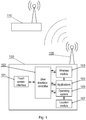
- Fig. 1 depicts an exemplary device implementing the method of the present invention.
- the mobile device (100) may be any device able to communicate via a wireless medium with another device (110) e.g. a smart-phone or a PDA or a portable PC or a Bluetooth headset or the like.
- the device comprises some kind of a user interface e.g. a touch interface (101) and a user interface controller (102) managing interaction with the mobile device (100).
- the mobile device (100) also comprises an operating system (105) and an applications layer (104), which are able to interact with the user interface controller (102) and a wireless module (103).
- the mobile device (100) is preferably equipped with an antenna (106), which is used to transmit and receive wireless signals to and from a stationary device (110, 201).
- the mobile device (100) is preferably also equipped with a location detection means or a location module (107) that allows the device to determine its location in space.
- This module (107) may be a GPS or an accelerometer or the like or may be a module reading location from another external entity including the stationary device (110, 201) or the like.
- the system also comprises typical hardware components (not shown) such as a data bus communicatively coupled to a memory. Additionally, other components of the system are communicatively coupled to the system bus so that they may be managed by a controller or microprocessor configured in particular to execute steps of the method according to the present invention.
- the memory may store computer program or programs executed by the controller in order to execute steps of the method according to the present invention as well as store one or more maps of signal strength.
- the following the description relates to the map of signal strength and the generation thereof.
- FIG. 2 An exemplary embodiment of the map of signal strength, in a form of a rectangular grid cells covering a defined, physical area, is shown in Fig. 2 . It is clear that other grid pattern than rectangular may be used as the smallest map areas.
- the map of signal strength (200), depicted in Fig. 2 corresponds to the strength of signal of the stationary device (110, 201).
- the stationary device (201) may be any wireless communication device e.g. a Wi-Fi router or a Bluetooth adapter or the like.
- a given mobile device (100) may have access to a plurality of maps of signal strength (200) corresponding to different devices (201). Upon connection to such a device having a corresponding map of signal strength (200), the mobile device (100) may take such map into account during a respective connection.
- the map of signal strength (200) comprises quantified values of the strength of a signal of the stationary device (201) ranging from 0 to 9 (or any arbitrarily chosen range of values representing a signal).
- the cell (202) comprises a value of 9, which represents a relatively strong signal
- the cell (203) comprises a value of 2 representing a relatively weak signal (defined for example by Signal to noise ratio).
- the values may actually be selected differently e.g. may be more precise e.g. representing an RSSI value (Received Signal Strength Indication) or a BER (Bit Error Rate) or the like (or a combination thereof) or may be even less precise e.g. in an environment where comparison of the values of strength of signal bears a significant error.
- the exemplary map of signal strength (200) also depicts an exemplary rapid change of strength of signal between cells (204) and (205), which may be caused by an obstacle e.g. a wall located as marked by element (206).
- the map of signal strength (200) also preferably comprises an additional value (207) per cell, which indicates the reliability coefficient of the respective signal.
- a reliability coefficient is a value of probability that the value (signal strength/property value) stored in the respective cell is correct, while another embodiment is an integer value being the higher the higher the reliability coefficient of the signal strength is. This value is used by the methods described later in the present disclosure to modify the map of signal strength and thus keep it adequate.
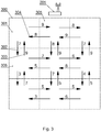
- map of signal strength (200) is an extended rectangular grid covering a defined area. Such exemplary grid is shown in Fig. 3 .
- the grid (300) represents the strength of a signal of the same device (201), which may be a Wi-Fi router or a Bluetooth adapter or the like.
- this grid (300) comprises quantified values representing the reliability coefficient coupled with each stored value of signal strength.
- the values stored in the cells of the grid (300) of said map are dependent on a direction, from which the particular cell is entered from. For instance the cell (301) is represented by value 8 when entered from the direction (304) of cell (305) and is represented by value 9 when entered from the direction (303) of cell (306).
- the destination cell (303) will be represented by value of 7 when entered from the direction (302) of the source cell (301).
- This exemplary embodiment of the map of signal strength aims at including in its definition potential differences in the strength of signal dependent on the direction of movement of a mobile device. Accordingly, in this map of signal strength (200), there is preferably also stored a reliability coefficient associated with each stored value.
- the above examples represent maps of signal strength (200) comprising the strength of a signal of a device (201). While this value may be used as a reference in the second step of the present method a better value is the value of strength of signal of the mobile device (100) moving through the map. Of course such value requires the device (201) or some external device to report the value back to the mobile device (100). In such case, the cells of the grid will contain the strength of signal of the mobile device (100) as seen by the stationary device (201). This is a preferred approach.
- the second step of the exemplary method of the present invention is the use of the generated map of signal strength in order to adapt transmission power of the mobile device (100).
- One embodiment of the second step of the present method may be used by a mobile device (100) in conjunction with an exemplary grid (200) map.
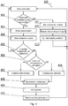
- the method (400) is depicted in Fig. 4 .
- the method (400) has been designed to incorporate verification of the map of signal strength (200).
- the verification of the map of strength of signal is depicted as step (410) and will be subsequently described in details.
- the method (400) begins at step (401) with detection of movement of the mobile device (100), said detection comprising a direction of the movement and an origin cell as well as a destination cell in the grid of a signal strength map (200).
- the location and its aforementioned parameters may be obtained in a variety of ways e.g. by GPS (The Global Positioning System) or using an accelerometer or any approximation of the aforementioned or the like. Such devices are called generically as location detection means.
- step (402) it is verified whether both source at and destination values of the strength of signal exist in a respective map of signal strength (200). If any of those parameters does not exist, the method waits at step (411) for the movement to finish, i.e. the mobile device (100) to arrive at a destination location, and moves to step (412) to measure the value of strength of the signal at the destination location and determine its initial reliability coefficient at step (413).
- the initial determination of the reliability coefficient strongly depends on the selected implementation or purpose of the creation of the map or the priorities of high level functionality inherent to the mobile device (100) or the like.
- the reliability coefficient may be equal to 1 to indicate a probability of a certain measurement, while in another embodiment the reliability coefficient may depend on the measured value to compensate for non-constant error of power measurement.
- the method obtains the source value at step (403) and obtains the destination value at step (404).
- step (405) it is verified at step (405) whether the value at destination location is same as at source location. If it is, then no power adjustment is needed and the method moves to step (401) to detect further movement.
- the method checks at step (406) whether the value of strength of signal at the destination cell is higher or lower then at the source cell. If the said value is lower, then at step (407) antenna power increase is computed. If at step (406) the said value is higher, then at step (414) power decrease is computed. The result of any and each of the steps (407, 414) is called an adjustment value of antenna power hereinafter (408).
- the actual value of the adjustment (408) depends on the selected implementation of strength map and the reliability coefficient.
- the antenna power may be increased proportionally to the increase in the signal strength predieted at step (405).
- this value may further be corrected by the reliability coefficient e.g. by reducing the adjustment value proportionally to the value of the reliability coefficient.
- step (409) the power of transmission is modified according to the adjustment value (408).
- step (410) the map of strength is verified i.e. it is checked if modifications are needed based on present situation. This step will be described in more detail later on. Finally, the method moves back to step (401) to detect further movement.
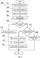
- step (501) the method waits for a movement, of a mobile device (100), to finish i.e. arrive at a destination location.
- step (502) the value at a destination cell is obtained at step (502) and a new strength of signal is measured at step (503) producing the adjustment value of antenna power (504).
- step (505) it is checked whether the adjustment value is higher then a threshold, the threshold being a predefined value dependent on the definition of the reliability coefficient that defines two values of strength of signal as substantially different.
- said threshold may be set at 5% in order to decrease a number of small adjustments to antenna power and react only to larger changes present in said map. In other words said threshold acts as a filter of changes of smaller magnitude.
- step (504) If the adjustment value (504) does not indicate the two values as substantially different, the method moves to step (506) to increase the reliability coefficient to reinforce its meaning. Subsequently, the method ends.
- step (505) If at step (505) the adjustment value (504) is higher then the threshold, the method moves to step (507) to check if the reliability coefficient is higher then a quality threshold, the quality threshold being a value from the domain of the reliability coefficient that allows the particular strength of signal to be considered substantially certain.
- the method decreases the reliability coefficient at step (508) and ends.
- step (507) the reliability coefficient is not higher than the quality threshold, the method moves to step (509) and modifies the existing strength of signal at the destination location.
- the modification may comprise substitution of the existing value for a newly measured one or computing a mean value or the like.
- step (510) the method sets the reliability coefficient similarly to step (413) of the method (400).
- step (511) the method (400) is executed again this time omitting step (410) (which initiated the execution of method (500)). This allows the device (100) to adjust the transition power according to method (400).
- An exemplary extension of the simple provided examples of the reliability coefficient and its modification may be created using the patent application EP14198454.2 to allow to make the reliability coefficient dependent on the frequency, with which it is being accessed to e.g. promote the locations or directions frequently preferred by the user of the device (100). This should not be construed as limiting to the present invention.
- Fig. 6 presents a high level overview of the method according to the present invention.
- the method starts at step (601) from obtaining a signal properties map (map of signal strength) by a mobile device (100), the map being predefined with reference to a source device (e.g. a stationary device (110)) wherein the map comprises a comparable value denoting at least one signal property and a comparable value denoting a reliability coefficient of the corresponding signal property.
- a source device e.g. a stationary device (110)
- step (602) there is executed detecting of a movement of the mobile device (100) with reference to the said map and an associated source and destination location. This is typically executed by a location module internal to the mobile device (100).
- step (603) there is executed adjusting antenna power of the mobile device based on a reading of the map (reliability coefficient and signal strength parameters) for the destination location determined in step (602).
- the method verifies the adjustment based on the actual reading of the signal property. This is effected by adjusting said reliability coefficient related to said destination on said signal properties map. Such adjustment depends strongly on the selected implementation of the reliability coefficient. In one embodiment the reliability coefficient may be increased or decreased by a constant value. In another embodiment the reliability coefficient change may be further corrected to be the higher the higher the change in the signal strength is. Lastly, the method returns to step (602).
- a user may also be directed to locations where required antenna power will be the lowest i.e. the battery usage of a mobile device will be the lowest due to required antenna power. Since the mobile device is in possession of a suitable signal strength map it may direct a user to a preferred location.
- the present invention allows to adjust the transition power of a wireless antenna based on the previous knowledge of the behaviour of signal's parameters before the actual condition that may trigger the change occurs. This in turn reduces the negative impact of e.g. increasing the transmission power too late i.e. only after the actual condition occurs. Further, the present method allows to decrease transmission power and thus reduce power consumption of a mobile device. Therefore, the invention provides a useful, concrete and tangible result.
- the present invention is applicable in communication between two devices using a wireless link wherein at least one of the devices is mobile.
- the invention affects antenna power and thus the machine or transformation test is fulfilled and the idea is not abstract.
- the present invention may take the form of an entirely hardware embodiment, an entirely software embodiment (including firmware, resident software, micro-code, etc.) or an embodiment combining software and hardware aspects that may all generally be referred to herein as a "circuit", "module” or "system”.
- the present invention may take the form of a computer program product embodied in any tangible medium of expression having computer usable program code embodied in the medium.
- the aforementioned method for prediction of transmission power in a wireless communication system may be performed and/or controlled by one or more computer programs.
- Such computer programs are typically executed by utilizing the computing resources in a computing device.
- Applications are stored on a non-transitory medium.
- An example of a non-transitory medium is a non-volatile memory, for example a flash memory while an example of a volatile memory is RAM.
- the computer instructions are executed by a processor.
- These memories are exemplary recording media for storing computer programs comprising computer-executable instructions performing all the steps of the computer-implemented method according the technical concept presented herein.
Landscapes
- Engineering & Computer Science (AREA)
- Computer Networks & Wireless Communication (AREA)
- Signal Processing (AREA)
- Mobile Radio Communication Systems (AREA)
Claims (9)
- Verfahren zur Vorhersage der Antennensendeleistung in einem drahtlosen Kommunikationssystem, wobei das Verfahren die folgenden Schritte umfasst:• Erhalten (601) einer Signaleigenschaftskarte durch ein Mobilgerät (100), wobei die Karte in Bezug auf eine Quellvorrichtung (110) vordefiniert ist, wobei die Karte für jede Zelle (202, 203) einen Vergleichswert umfasst, der mindestens eine Signaleigenschaft bezeichnet, und einen Vergleichswert, der einen Zuverlässigkeitskoeffizienten (207) bezeichnet, gekoppelt mit jeder entsprechenden Signaleigenschaft;• Erkennen (602) einer Bewegung des Mobilgeräts (100) in Bezug auf die Karte und eine zugeordnete Ausgangs- und Zielposition;• Anpassen (603) der Antennensendeleistung des Mobilgeräts (100) auf der Basis eines erhaltenen Wertes aus der Signaleigenschaftskarte des zugeordneten Zuverlässigkeitskoeffizienten und der Signaleigenschaften für das Ziel;• Verifizieren (604) der Anpassung auf der Basis des tatsächlichen Wertes der Signaleigenschaft, und als Folge der Verifizierung, Anpassen des Zuverlässigkeitskoeffizienten in Bezug auf eine Zelle (202, 203) entsprechend dem Ziel auf der Signaleigenschaftskarte.
- Verfahren nach Anspruch 1, wobei der Vergleichswert, der mindestens eine Signaleigenschaft bezeichnet, mindestens eines der folgenden ist: ein Indikator für die Empfangssignalstärke oder die Bitfehlerrate oder die Signalstärke.
- Verfahren nach Anspruch 1, wobei der Zuverlässigkeitskoeffizient (207) ein Wahrscheinlichkeitswert dafür ist, dass der in der entsprechenden Zelle gespeicherte entsprechende Vergleichswert, der mindestens eine Signaleigenschaft bezeichnet, richtig ist.
- Verfahren nach Anspruch 1, wobei der Vergleichswert, der mindestens eine Signaleigenschaft bezeichnet, abhängig ist von einer Richtung, aus welcher der Eintritt in die jeweilige Zelle der Karte erfolgt.
- Verfahren nach Anspruch 1, wobei der Anpassungsschritt einen Schwellenwert berücksichtigt, der als ein Anpassungsfilter fungiert.
- Verfahren nach Anspruch 1, wobei der initiale Zuverlässigkeitskoeffizient ein fester Wert ist oder abhängig ist von der gemessenen Signalstärke, die an das Mobilgerät (100) zurückgemeldet wird.
- Computerprogramm, das Programmcodemittel umfasst, zur Ausführung aller Schritte des computerimplementierten Verfahrens nach Anspruch 1, wenn das Programm auf einem Computer ausgeführt wird.
- Computerlesbares Medium, das durch einen Computer ausführbare Anweisungen speichert, die alle Schritte des computerimplementierten Verfahrens nach Anspruch 1 ausführen, wenn sie auf einem Computer ausgeführt werden.
- Vorrichtung zur Vorhersage der Antennensendeleistung in einem drahtlosen Kommunikationssystem, wobei die Vorrichtung folgendes umfasst:• eine Antenne (106);• eine Standorterkennungsvorrichtung (107);• einen Speicher, der zum Speichern einer oder mehrerer Signaleigenschaftskarten gestaltet ist;• eine Steuereinheit, die zur Ausführung der Schritte des Verfahrens nach Anspruch 1 gestaltet ist.
Priority Applications (1)
| Application Number | Priority Date | Filing Date | Title |
|---|---|---|---|
| EP17187415.9A EP3448093B1 (de) | 2017-08-23 | 2017-08-23 | System und verfahren zur vorhersage der sendeleistung in einem drahtloskommunikationssystem |
Applications Claiming Priority (1)
| Application Number | Priority Date | Filing Date | Title |
|---|---|---|---|
| EP17187415.9A EP3448093B1 (de) | 2017-08-23 | 2017-08-23 | System und verfahren zur vorhersage der sendeleistung in einem drahtloskommunikationssystem |
Publications (2)
| Publication Number | Publication Date |
|---|---|
| EP3448093A1 EP3448093A1 (de) | 2019-02-27 |
| EP3448093B1 true EP3448093B1 (de) | 2020-10-07 |
Family
ID=59846311
Family Applications (1)
| Application Number | Title | Priority Date | Filing Date |
|---|---|---|---|
| EP17187415.9A Active EP3448093B1 (de) | 2017-08-23 | 2017-08-23 | System und verfahren zur vorhersage der sendeleistung in einem drahtloskommunikationssystem |
Country Status (1)
| Country | Link |
|---|---|
| EP (1) | EP3448093B1 (de) |
Families Citing this family (1)
| Publication number | Priority date | Publication date | Assignee | Title |
|---|---|---|---|---|
| CN114640948A (zh) * | 2022-01-23 | 2022-06-17 | 深圳银星智能集团股份有限公司 | 控制方法及通信设备 |
Family Cites Families (6)
| Publication number | Priority date | Publication date | Assignee | Title |
|---|---|---|---|---|
| JP4679686B2 (ja) | 2000-02-07 | 2011-04-27 | パナソニック株式会社 | 無線通信装置及び送信電力制御方法 |
| US7706827B2 (en) * | 2006-02-15 | 2010-04-27 | Broadcom Corporation | Method and apparatus for processing transmit power control (TPC) commands in a wideband CDMA (WCDMA) network based on a sign metric |
| US7904092B2 (en) * | 2007-01-04 | 2011-03-08 | Cisco Technology, Inc. | Locally adjusted radio frequency coverage maps in wireless networks |
| WO2009001154A1 (en) | 2007-06-28 | 2008-12-31 | Nokia Corporation | Radiated power optimization for a mobile radio transmitter/receiver having an antenna |
| US8744511B2 (en) | 2009-09-04 | 2014-06-03 | Qualcomm Incorporated | Output power control for advanced WLAN and bluetooth-amp systems |
| JP2013143575A (ja) * | 2012-01-06 | 2013-07-22 | Fujitsu Mobile Communications Ltd | 無線通信端末装置及び無線通信端末装置制御方法 |
-
2017
- 2017-08-23 EP EP17187415.9A patent/EP3448093B1/de active Active
Non-Patent Citations (1)
| Title |
|---|
| None * |
Also Published As
| Publication number | Publication date |
|---|---|
| EP3448093A1 (de) | 2019-02-27 |
Similar Documents
| Publication | Publication Date | Title |
|---|---|---|
| CA2554079C (en) | Method and apparatus for fast data rate ramp up in node b scheduling of ue uplink | |
| KR101273082B1 (ko) | 상향 링크 전송 전력 제어를 위한 피드백 생성 방법 및 시스템 | |
| US9629201B2 (en) | Using Wi-Fi as human control interface | |
| US20210051678A1 (en) | Wireless communication system, wireless communication method, base station, and terminal | |
| CN107623554B (zh) | 一种基于信任值的协作频谱感知方法、认知无线网络 | |
| EP3162153A1 (de) | Beurteilung der schwellenkonfiguration eines freien kanals | |
| CN102404057A (zh) | 提高gsm终端射频发射部分辐射性能的方法 | |
| EP3618484A1 (de) | Verfahren und vorrichtung zur anpassung des absenkwinkels einer antenne | |
| CN113573229A (zh) | 一种定位校正方法及装置 | |
| EP3448093B1 (de) | System und verfahren zur vorhersage der sendeleistung in einem drahtloskommunikationssystem | |
| US11714469B2 (en) | Temperature control management of electronic device based on number of heat-emitting components in compartment | |
| US10038984B1 (en) | Wireless positioning method and wireless positioning device in indoor environment | |
| JP7459457B2 (ja) | 位置推定装置、移動体装置、空間データ提示装置、位置推定方法及びプログラム | |
| CN110972183A (zh) | 信息上报方法及用户终端、计算机可读存储介质 | |
| CN103532905A (zh) | 基于硬判决的信噪比估计方法和装置 | |
| AU2013202735B2 (en) | Determining Effects on Communication Signals | |
| KR20120072148A (ko) | 간섭 회피 기능을 사용하는 무선 통신 시스템의 간섭 분석을 위한 데이터 처리량 도출 방법 | |
| US10720702B2 (en) | Method and device for correcting antenna phase | |
| EP2910067B1 (de) | Verfahren und vorrichtung zur leistungssteuerung in einem drahtlosen kommunikationsnetz | |
| CN102224753B (zh) | 基于格式的功率控制 | |
| KR20110078562A (ko) | 정확도를 향상시킨 실시간 위치추적 시스템 및 방법 | |
| US20250150842A1 (en) | Computer simulation for the design of wireless network infrastructure | |
| KR102415247B1 (ko) | Ftm 방식의 태그기반 하이브리드 위치 측위 및 태그 운용 방법 및 장치 | |
| CN101599783A (zh) | 一种调整功率的方法及装置 | |
| Kim et al. | Testbed verification of spectrum access opportunity detection in cognitive radio networks |
Legal Events
| Date | Code | Title | Description |
|---|---|---|---|
| PUAI | Public reference made under article 153(3) epc to a published international application that has entered the european phase |
Free format text: ORIGINAL CODE: 0009012 |
|
| STAA | Information on the status of an ep patent application or granted ep patent |
Free format text: STATUS: THE APPLICATION HAS BEEN PUBLISHED |
|
| AK | Designated contracting states |
Kind code of ref document: A1 Designated state(s): AL AT BE BG CH CY CZ DE DK EE ES FI FR GB GR HR HU IE IS IT LI LT LU LV MC MK MT NL NO PL PT RO RS SE SI SK SM TR |
|
| AX | Request for extension of the european patent |
Extension state: BA ME |
|
| STAA | Information on the status of an ep patent application or granted ep patent |
Free format text: STATUS: REQUEST FOR EXAMINATION WAS MADE |
|
| 17P | Request for examination filed |
Effective date: 20190704 |
|
| RBV | Designated contracting states (corrected) |
Designated state(s): AL AT BE BG CH CY CZ DE DK EE ES FI FR GB GR HR HU IE IS IT LI LT LU LV MC MK MT NL NO PL PT RO RS SE SI SK SM TR |
|
| RIC1 | Information provided on ipc code assigned before grant |
Ipc: H04W 52/24 20090101ALN20200409BHEP Ipc: H04W 52/28 20090101ALI20200409BHEP Ipc: H04W 84/12 20090101ALN20200409BHEP Ipc: H04W 52/22 20090101ALI20200409BHEP Ipc: H04W 52/26 20090101ALN20200409BHEP Ipc: H04W 52/14 20090101AFI20200409BHEP |
|
| GRAP | Despatch of communication of intention to grant a patent |
Free format text: ORIGINAL CODE: EPIDOSNIGR1 |
|
| STAA | Information on the status of an ep patent application or granted ep patent |
Free format text: STATUS: GRANT OF PATENT IS INTENDED |
|
| INTG | Intention to grant announced |
Effective date: 20200526 |
|
| RAP1 | Party data changed (applicant data changed or rights of an application transferred) |
Owner name: ADVANCED DIGITAL BROADCAST S.A. |
|
| GRAS | Grant fee paid |
Free format text: ORIGINAL CODE: EPIDOSNIGR3 |
|
| GRAA | (expected) grant |
Free format text: ORIGINAL CODE: 0009210 |
|
| STAA | Information on the status of an ep patent application or granted ep patent |
Free format text: STATUS: THE PATENT HAS BEEN GRANTED |
|
| AK | Designated contracting states |
Kind code of ref document: B1 Designated state(s): AL AT BE BG CH CY CZ DE DK EE ES FI FR GB GR HR HU IE IS IT LI LT LU LV MC MK MT NL NO PL PT RO RS SE SI SK SM TR |
|
| REG | Reference to a national code |
Ref country code: GB Ref legal event code: FG4D |
|
| REG | Reference to a national code |
Ref country code: CH Ref legal event code: EP Ref country code: AT Ref legal event code: REF Ref document number: 1322556 Country of ref document: AT Kind code of ref document: T Effective date: 20201015 |
|
| REG | Reference to a national code |
Ref country code: IE Ref legal event code: FG4D |
|
| REG | Reference to a national code |
Ref country code: DE Ref legal event code: R096 Ref document number: 602017024913 Country of ref document: DE |
|
| REG | Reference to a national code |
Ref country code: NL Ref legal event code: MP Effective date: 20201007 |
|
| REG | Reference to a national code |
Ref country code: AT Ref legal event code: MK05 Ref document number: 1322556 Country of ref document: AT Kind code of ref document: T Effective date: 20201007 |
|
| PG25 | Lapsed in a contracting state [announced via postgrant information from national office to epo] |
Ref country code: PT Free format text: LAPSE BECAUSE OF FAILURE TO SUBMIT A TRANSLATION OF THE DESCRIPTION OR TO PAY THE FEE WITHIN THE PRESCRIBED TIME-LIMIT Effective date: 20210208 Ref country code: RS Free format text: LAPSE BECAUSE OF FAILURE TO SUBMIT A TRANSLATION OF THE DESCRIPTION OR TO PAY THE FEE WITHIN THE PRESCRIBED TIME-LIMIT Effective date: 20201007 Ref country code: NO Free format text: LAPSE BECAUSE OF FAILURE TO SUBMIT A TRANSLATION OF THE DESCRIPTION OR TO PAY THE FEE WITHIN THE PRESCRIBED TIME-LIMIT Effective date: 20210107 Ref country code: GR Free format text: LAPSE BECAUSE OF FAILURE TO SUBMIT A TRANSLATION OF THE DESCRIPTION OR TO PAY THE FEE WITHIN THE PRESCRIBED TIME-LIMIT Effective date: 20210108 Ref country code: FI Free format text: LAPSE BECAUSE OF FAILURE TO SUBMIT A TRANSLATION OF THE DESCRIPTION OR TO PAY THE FEE WITHIN THE PRESCRIBED TIME-LIMIT Effective date: 20201007 |
|
| REG | Reference to a national code |
Ref country code: LT Ref legal event code: MG4D |
|
| PG25 | Lapsed in a contracting state [announced via postgrant information from national office to epo] |
Ref country code: SE Free format text: LAPSE BECAUSE OF FAILURE TO SUBMIT A TRANSLATION OF THE DESCRIPTION OR TO PAY THE FEE WITHIN THE PRESCRIBED TIME-LIMIT Effective date: 20201007 Ref country code: ES Free format text: LAPSE BECAUSE OF FAILURE TO SUBMIT A TRANSLATION OF THE DESCRIPTION OR TO PAY THE FEE WITHIN THE PRESCRIBED TIME-LIMIT Effective date: 20201007 Ref country code: AT Free format text: LAPSE BECAUSE OF FAILURE TO SUBMIT A TRANSLATION OF THE DESCRIPTION OR TO PAY THE FEE WITHIN THE PRESCRIBED TIME-LIMIT Effective date: 20201007 Ref country code: BG Free format text: LAPSE BECAUSE OF FAILURE TO SUBMIT A TRANSLATION OF THE DESCRIPTION OR TO PAY THE FEE WITHIN THE PRESCRIBED TIME-LIMIT Effective date: 20210107 Ref country code: PL Free format text: LAPSE BECAUSE OF FAILURE TO SUBMIT A TRANSLATION OF THE DESCRIPTION OR TO PAY THE FEE WITHIN THE PRESCRIBED TIME-LIMIT Effective date: 20201007 Ref country code: IS Free format text: LAPSE BECAUSE OF FAILURE TO SUBMIT A TRANSLATION OF THE DESCRIPTION OR TO PAY THE FEE WITHIN THE PRESCRIBED TIME-LIMIT Effective date: 20210207 Ref country code: LV Free format text: LAPSE BECAUSE OF FAILURE TO SUBMIT A TRANSLATION OF THE DESCRIPTION OR TO PAY THE FEE WITHIN THE PRESCRIBED TIME-LIMIT Effective date: 20201007 |
|
| PG25 | Lapsed in a contracting state [announced via postgrant information from national office to epo] |
Ref country code: NL Free format text: LAPSE BECAUSE OF FAILURE TO SUBMIT A TRANSLATION OF THE DESCRIPTION OR TO PAY THE FEE WITHIN THE PRESCRIBED TIME-LIMIT Effective date: 20201007 Ref country code: HR Free format text: LAPSE BECAUSE OF FAILURE TO SUBMIT A TRANSLATION OF THE DESCRIPTION OR TO PAY THE FEE WITHIN THE PRESCRIBED TIME-LIMIT Effective date: 20201007 |
|
| REG | Reference to a national code |
Ref country code: DE Ref legal event code: R097 Ref document number: 602017024913 Country of ref document: DE |
|
| PG25 | Lapsed in a contracting state [announced via postgrant information from national office to epo] |
Ref country code: LT Free format text: LAPSE BECAUSE OF FAILURE TO SUBMIT A TRANSLATION OF THE DESCRIPTION OR TO PAY THE FEE WITHIN THE PRESCRIBED TIME-LIMIT Effective date: 20201007 Ref country code: SM Free format text: LAPSE BECAUSE OF FAILURE TO SUBMIT A TRANSLATION OF THE DESCRIPTION OR TO PAY THE FEE WITHIN THE PRESCRIBED TIME-LIMIT Effective date: 20201007 Ref country code: CZ Free format text: LAPSE BECAUSE OF FAILURE TO SUBMIT A TRANSLATION OF THE DESCRIPTION OR TO PAY THE FEE WITHIN THE PRESCRIBED TIME-LIMIT Effective date: 20201007 Ref country code: EE Free format text: LAPSE BECAUSE OF FAILURE TO SUBMIT A TRANSLATION OF THE DESCRIPTION OR TO PAY THE FEE WITHIN THE PRESCRIBED TIME-LIMIT Effective date: 20201007 Ref country code: RO Free format text: LAPSE BECAUSE OF FAILURE TO SUBMIT A TRANSLATION OF THE DESCRIPTION OR TO PAY THE FEE WITHIN THE PRESCRIBED TIME-LIMIT Effective date: 20201007 Ref country code: SK Free format text: LAPSE BECAUSE OF FAILURE TO SUBMIT A TRANSLATION OF THE DESCRIPTION OR TO PAY THE FEE WITHIN THE PRESCRIBED TIME-LIMIT Effective date: 20201007 |
|
| PLBE | No opposition filed within time limit |
Free format text: ORIGINAL CODE: 0009261 |
|
| STAA | Information on the status of an ep patent application or granted ep patent |
Free format text: STATUS: NO OPPOSITION FILED WITHIN TIME LIMIT |
|
| PG25 | Lapsed in a contracting state [announced via postgrant information from national office to epo] |
Ref country code: DK Free format text: LAPSE BECAUSE OF FAILURE TO SUBMIT A TRANSLATION OF THE DESCRIPTION OR TO PAY THE FEE WITHIN THE PRESCRIBED TIME-LIMIT Effective date: 20201007 |
|
| 26N | No opposition filed |
Effective date: 20210708 |
|
| PG25 | Lapsed in a contracting state [announced via postgrant information from national office to epo] |
Ref country code: IT Free format text: LAPSE BECAUSE OF FAILURE TO SUBMIT A TRANSLATION OF THE DESCRIPTION OR TO PAY THE FEE WITHIN THE PRESCRIBED TIME-LIMIT Effective date: 20201007 Ref country code: AL Free format text: LAPSE BECAUSE OF FAILURE TO SUBMIT A TRANSLATION OF THE DESCRIPTION OR TO PAY THE FEE WITHIN THE PRESCRIBED TIME-LIMIT Effective date: 20201007 |
|
| PG25 | Lapsed in a contracting state [announced via postgrant information from national office to epo] |
Ref country code: SI Free format text: LAPSE BECAUSE OF FAILURE TO SUBMIT A TRANSLATION OF THE DESCRIPTION OR TO PAY THE FEE WITHIN THE PRESCRIBED TIME-LIMIT Effective date: 20201007 |
|
| REG | Reference to a national code |
Ref country code: CH Ref legal event code: PL |
|
| PG25 | Lapsed in a contracting state [announced via postgrant information from national office to epo] |
Ref country code: MC Free format text: LAPSE BECAUSE OF FAILURE TO SUBMIT A TRANSLATION OF THE DESCRIPTION OR TO PAY THE FEE WITHIN THE PRESCRIBED TIME-LIMIT Effective date: 20201007 |
|
| REG | Reference to a national code |
Ref country code: BE Ref legal event code: MM Effective date: 20210831 |
|
| PG25 | Lapsed in a contracting state [announced via postgrant information from national office to epo] |
Ref country code: LI Free format text: LAPSE BECAUSE OF NON-PAYMENT OF DUE FEES Effective date: 20210831 Ref country code: CH Free format text: LAPSE BECAUSE OF NON-PAYMENT OF DUE FEES Effective date: 20210831 |
|
| PG25 | Lapsed in a contracting state [announced via postgrant information from national office to epo] |
Ref country code: IS Free format text: LAPSE BECAUSE OF FAILURE TO SUBMIT A TRANSLATION OF THE DESCRIPTION OR TO PAY THE FEE WITHIN THE PRESCRIBED TIME-LIMIT Effective date: 20210207 Ref country code: LU Free format text: LAPSE BECAUSE OF NON-PAYMENT OF DUE FEES Effective date: 20210823 |
|
| PG25 | Lapsed in a contracting state [announced via postgrant information from national office to epo] |
Ref country code: IE Free format text: LAPSE BECAUSE OF NON-PAYMENT OF DUE FEES Effective date: 20210823 Ref country code: BE Free format text: LAPSE BECAUSE OF NON-PAYMENT OF DUE FEES Effective date: 20210831 |
|
| PG25 | Lapsed in a contracting state [announced via postgrant information from national office to epo] |
Ref country code: CY Free format text: LAPSE BECAUSE OF FAILURE TO SUBMIT A TRANSLATION OF THE DESCRIPTION OR TO PAY THE FEE WITHIN THE PRESCRIBED TIME-LIMIT Effective date: 20201007 |
|
| PG25 | Lapsed in a contracting state [announced via postgrant information from national office to epo] |
Ref country code: HU Free format text: LAPSE BECAUSE OF FAILURE TO SUBMIT A TRANSLATION OF THE DESCRIPTION OR TO PAY THE FEE WITHIN THE PRESCRIBED TIME-LIMIT; INVALID AB INITIO Effective date: 20170823 |
|
| PG25 | Lapsed in a contracting state [announced via postgrant information from national office to epo] |
Ref country code: MK Free format text: LAPSE BECAUSE OF FAILURE TO SUBMIT A TRANSLATION OF THE DESCRIPTION OR TO PAY THE FEE WITHIN THE PRESCRIBED TIME-LIMIT Effective date: 20201007 |
|
| PG25 | Lapsed in a contracting state [announced via postgrant information from national office to epo] |
Ref country code: TR Free format text: LAPSE BECAUSE OF FAILURE TO SUBMIT A TRANSLATION OF THE DESCRIPTION OR TO PAY THE FEE WITHIN THE PRESCRIBED TIME-LIMIT Effective date: 20201007 |
|
| PG25 | Lapsed in a contracting state [announced via postgrant information from national office to epo] |
Ref country code: MT Free format text: LAPSE BECAUSE OF FAILURE TO SUBMIT A TRANSLATION OF THE DESCRIPTION OR TO PAY THE FEE WITHIN THE PRESCRIBED TIME-LIMIT Effective date: 20201007 |
|
| PGFP | Annual fee paid to national office [announced via postgrant information from national office to epo] |
Ref country code: DE Payment date: 20250827 Year of fee payment: 9 |
|
| PGFP | Annual fee paid to national office [announced via postgrant information from national office to epo] |
Ref country code: GB Payment date: 20250827 Year of fee payment: 9 |
|
| PGFP | Annual fee paid to national office [announced via postgrant information from national office to epo] |
Ref country code: FR Payment date: 20250825 Year of fee payment: 9 |