EP3448095B1 - Dispositif terminal, dispositif de station de base et procédés de communication correspendants - Google Patents
Dispositif terminal, dispositif de station de base et procédés de communication correspendants Download PDFInfo
- Publication number
- EP3448095B1 EP3448095B1 EP17785657.2A EP17785657A EP3448095B1 EP 3448095 B1 EP3448095 B1 EP 3448095B1 EP 17785657 A EP17785657 A EP 17785657A EP 3448095 B1 EP3448095 B1 EP 3448095B1
- Authority
- EP
- European Patent Office
- Prior art keywords
- random access
- terminal apparatus
- access preamble
- transmit
- pdcch order
- Prior art date
- Legal status (The legal status is an assumption and is not a legal conclusion. Google has not performed a legal analysis and makes no representation as to the accuracy of the status listed.)
- Active
Links
Images



Classifications
-
- H—ELECTRICITY
- H04—ELECTRIC COMMUNICATION TECHNIQUE
- H04W—WIRELESS COMMUNICATION NETWORKS
- H04W74/00—Wireless channel access
- H04W74/08—Non-scheduled access, e.g. ALOHA
- H04W74/0808—Non-scheduled access, e.g. ALOHA using carrier sensing, e.g. carrier sense multiple access [CSMA]
-
- H—ELECTRICITY
- H04—ELECTRIC COMMUNICATION TECHNIQUE
- H04W—WIRELESS COMMUNICATION NETWORKS
- H04W74/00—Wireless channel access
- H04W74/002—Transmission of channel access control information
- H04W74/004—Transmission of channel access control information in the uplink, i.e. towards network
-
- H—ELECTRICITY
- H04—ELECTRIC COMMUNICATION TECHNIQUE
- H04J—MULTIPLEX COMMUNICATION
- H04J11/00—Orthogonal multiplex systems, e.g. using WALSH codes
-
- H—ELECTRICITY
- H04—ELECTRIC COMMUNICATION TECHNIQUE
- H04L—TRANSMISSION OF DIGITAL INFORMATION, e.g. TELEGRAPHIC COMMUNICATION
- H04L5/00—Arrangements affording multiple use of the transmission path
- H04L5/0001—Arrangements for dividing the transmission path
- H04L5/0003—Two-dimensional division
- H04L5/0005—Time-frequency
- H04L5/0007—Time-frequency the frequencies being orthogonal, e.g. OFDM(A) or DMT
- H04L5/001—Time-frequency the frequencies being orthogonal, e.g. OFDM(A) or DMT the frequencies being arranged in component carriers
-
- H—ELECTRICITY
- H04—ELECTRIC COMMUNICATION TECHNIQUE
- H04W—WIRELESS COMMUNICATION NETWORKS
- H04W16/00—Network planning, e.g. coverage or traffic planning tools; Network deployment, e.g. resource partitioning or cells structures
- H04W16/14—Spectrum sharing arrangements between different networks
-
- H—ELECTRICITY
- H04—ELECTRIC COMMUNICATION TECHNIQUE
- H04W—WIRELESS COMMUNICATION NETWORKS
- H04W72/00—Local resource management
- H04W72/04—Wireless resource allocation
-
- H—ELECTRICITY
- H04—ELECTRIC COMMUNICATION TECHNIQUE
- H04W—WIRELESS COMMUNICATION NETWORKS
- H04W72/00—Local resource management
- H04W72/04—Wireless resource allocation
- H04W72/044—Wireless resource allocation based on the type of the allocated resource
- H04W72/0446—Resources in time domain, e.g. slots or frames
-
- H—ELECTRICITY
- H04—ELECTRIC COMMUNICATION TECHNIQUE
- H04W—WIRELESS COMMUNICATION NETWORKS
- H04W72/00—Local resource management
- H04W72/04—Wireless resource allocation
- H04W72/044—Wireless resource allocation based on the type of the allocated resource
- H04W72/0473—Wireless resource allocation based on the type of the allocated resource the resource being transmission power
-
- H—ELECTRICITY
- H04—ELECTRIC COMMUNICATION TECHNIQUE
- H04W—WIRELESS COMMUNICATION NETWORKS
- H04W72/00—Local resource management
- H04W72/20—Control channels or signalling for resource management
- H04W72/23—Control channels or signalling for resource management in the downlink direction of a wireless link, i.e. towards a terminal
-
- H—ELECTRICITY
- H04—ELECTRIC COMMUNICATION TECHNIQUE
- H04W—WIRELESS COMMUNICATION NETWORKS
- H04W72/00—Local resource management
- H04W72/50—Allocation or scheduling criteria for wireless resources
- H04W72/53—Allocation or scheduling criteria for wireless resources based on regulatory allocation policies
-
- H—ELECTRICITY
- H04—ELECTRIC COMMUNICATION TECHNIQUE
- H04W—WIRELESS COMMUNICATION NETWORKS
- H04W74/00—Wireless channel access
- H04W74/002—Transmission of channel access control information
- H04W74/006—Transmission of channel access control information in the downlink, i.e. towards the terminal
-
- H—ELECTRICITY
- H04—ELECTRIC COMMUNICATION TECHNIQUE
- H04W—WIRELESS COMMUNICATION NETWORKS
- H04W74/00—Wireless channel access
- H04W74/02—Hybrid access
-
- H—ELECTRICITY
- H04—ELECTRIC COMMUNICATION TECHNIQUE
- H04W—WIRELESS COMMUNICATION NETWORKS
- H04W74/00—Wireless channel access
- H04W74/08—Non-scheduled access, e.g. ALOHA
-
- H—ELECTRICITY
- H04—ELECTRIC COMMUNICATION TECHNIQUE
- H04W—WIRELESS COMMUNICATION NETWORKS
- H04W74/00—Wireless channel access
- H04W74/08—Non-scheduled access, e.g. ALOHA
- H04W74/0833—Random access procedures, e.g. with 4-step access
-
- H—ELECTRICITY
- H04—ELECTRIC COMMUNICATION TECHNIQUE
- H04W—WIRELESS COMMUNICATION NETWORKS
- H04W74/00—Wireless channel access
- H04W74/08—Non-scheduled access, e.g. ALOHA
- H04W74/0866—Non-scheduled access, e.g. ALOHA using a dedicated channel for access
-
- H—ELECTRICITY
- H04—ELECTRIC COMMUNICATION TECHNIQUE
- H04W—WIRELESS COMMUNICATION NETWORKS
- H04W76/00—Connection management
- H04W76/20—Manipulation of established connections
- H04W76/27—Transitions between radio resource control [RRC] states
-
- H—ELECTRICITY
- H04—ELECTRIC COMMUNICATION TECHNIQUE
- H04W—WIRELESS COMMUNICATION NETWORKS
- H04W80/00—Wireless network protocols or protocol adaptations to wireless operation
- H04W80/02—Data link layer protocols
-
- H—ELECTRICITY
- H04—ELECTRIC COMMUNICATION TECHNIQUE
- H04W—WIRELESS COMMUNICATION NETWORKS
- H04W80/00—Wireless network protocols or protocol adaptations to wireless operation
- H04W80/08—Upper layer protocols
-
- H—ELECTRICITY
- H04—ELECTRIC COMMUNICATION TECHNIQUE
- H04W—WIRELESS COMMUNICATION NETWORKS
- H04W52/00—Power management, e.g. Transmission Power Control [TPC] or power classes
- H04W52/04—Transmission power control [TPC]
- H04W52/06—TPC algorithms
- H04W52/14—Separate analysis of uplink or downlink
- H04W52/146—Uplink power control
-
- H—ELECTRICITY
- H04—ELECTRIC COMMUNICATION TECHNIQUE
- H04W—WIRELESS COMMUNICATION NETWORKS
- H04W52/00—Power management, e.g. Transmission Power Control [TPC] or power classes
- H04W52/04—Transmission power control [TPC]
- H04W52/18—TPC being performed according to specific parameters
- H04W52/24—TPC being performed according to specific parameters using SIR [Signal to Interference Ratio] or other wireless path parameters
- H04W52/247—TPC being performed according to specific parameters using SIR [Signal to Interference Ratio] or other wireless path parameters where the output power of a terminal is based on a path parameter sent by another terminal
-
- H—ELECTRICITY
- H04—ELECTRIC COMMUNICATION TECHNIQUE
- H04W—WIRELESS COMMUNICATION NETWORKS
- H04W52/00—Power management, e.g. Transmission Power Control [TPC] or power classes
- H04W52/04—Transmission power control [TPC]
- H04W52/38—TPC being performed in particular situations
- H04W52/50—TPC being performed in particular situations at the moment of starting communication in a multiple access environment
Definitions
- An aspect of the present invention relates to a terminal apparatus, a base station apparatus and corresponding methods.
- LTE Long Term Evolution
- EUTRA Evolved Universal Terrestrial Radio Access
- a base station apparatus is also referred to as an evolved NodeB (eNodeB)
- a terminal apparatus is also referred to as a User Equipment (UE).
- LTE is a cellular communication system in which multiple areas covered by the base station apparatuses are deployed to form a cellular structure.
- a single base station apparatus may manage multiple cells.
- Non Patent Literature 1 career aggregation which is a technique for a terminal apparatus to perform simultaneous transmission and/or reception in multiple serving cells (component careers) has been specified (Non Patent Literature 1, 2, 3, 4, and 5).
- LAA Licenses Assisted Access
- Non Patent Literature 6 function enhancement of Licenses Assisted Access (LAA) and carrier aggregation using uplink carriers in an unlicensed band has been studied (Non Patent Literature 6).
- PRACH Physical Random Access CHannel
- WO 2015/083997 describes a method for performing a random access procedure for coverage enhancement.
- the method comprises the steps of: transmitting a random access preamble repetitively to a certain cell on the basis of a predetermined repetition level; when a random access response has not received within a random access response window, reconfiguring the repetition level; and retransmitting the random access preamble repetitively on the basis of the reconfigured repetition level.
- An aspect of the present invention provides a terminal apparatus capable of efficiently performing a random access procedure, a communication method to be used by the terminal apparatus, a base station apparatus capable of efficiently performing a random access procedure and a communication method to be used by the base station apparatus.
- terminal apparatus There is provided a terminal apparatus, a communication method used for a terminal apparatus, a base station apparatus and a communication method used for a base station apparatus as defined in the independent claims, respectively.
- Preferred embodiments are set forth in the dependent claims.
- a terminal apparatus can perform a random access procedure efficiently. Further, a base station apparatus can perform a random access procedure efficiently.
- FIG. 1 is a conceptual diagram of a radio communication system.
- the radio communication system includes terminal apparatuses 1A to 1C and the base station apparatus 3.
- Each of the terminal apparatuses 1A to 1C is referred to as the terminal apparatus 1 below.
- Multiple serving cells are configured for the terminal apparatus 1.
- a technology in which the terminal apparatus 1 communicates via the multiple serving cells is referred to as cell aggregation or carrier aggregation.
- An aspect of the present invention may be applied to each of the multiple serving cells configured for the terminal apparatus 1.
- an aspect of the present invention may be applied to some of the configured multiple serving cells.
- an aspect of the present invention may be applied to each of groups of the configured multiple serving cells.
- an aspect of the present invention may be applied to some of the groups of the configured multiple serving cells.
- the multiple serving cells include at least one primary cell.
- the multiple serving cells may include one or multiple secondary cells.
- the multiple serving cells may include one or multiple Licensed Assisted Access (LAA) cells.
- LAA cell is also referred to as an LAA secondary cell.
- the primary cell is a serving cell in which an initial connection establishment procedure has been performed, a serving cell in which a connection re-establishment procedure has been started, or a cell indicated as a primary cell during a handover procedure.
- RRC Radio Resource Control
- the primary cell may be included in a licensed band.
- the LAA cell may be included in an unlicensed band.
- the secondary cell may be included in any one of the licensed band and the unlicensed band.
- a carrier corresponding to a serving cell in a downlink is referred to as a downlink component carrier.
- a carrier corresponding to a serving cell in an uplink is referred to as an uplink component carrier.
- the downlink component carrier and the uplink component carrier are collectively referred to as a component carrier.
- the terminal apparatus 1 can perform simultaneous transmission and/or reception on multiple physical channels in multiple serving cells (component careers).
- a single physical channel is transmitted in a single serving cell (component carrier) of the multiple serving cells (component carriers).
- the following uplink physical channels are used for uplink radio communication from the terminal apparatus 1 to the base station apparatus 3.
- the uplink physical channels are used for transmission of information output from higher layers.
- the PUCCH is used for transmission of Uplink Control Information (UCI).
- UCI Uplink Control Information
- the PUSCH is used for transmission of uplink data (Transport block, UpLink-Shared CHannel (UL-SCH)).
- the PUSCH may be used to transmit Uplink Control Information together with the uplink data.
- the PRACH is used to transmit a random access preamble.
- the following uplink physical signal is used in the uplink radio communication.
- the uplink physical signal is not used for transmission of information output from the higher layer, but is used by a physical layer.
- uplink reference signals In an example, the following two types of uplink reference signals are used.
- the DMRS is associated with transmission of the PUSCH or the PUCCH.
- the DMRS is time-multiplexed with the PUSCH or the PUCCH.
- the base station apparatus 3 uses the DMRS in order to perform channel compensation of the PUSCH or the PUCCH.
- the SRS is not associated with the transmission of the PUSCH or the PUCCH.
- the base station apparatus 3 may use the SRS for measuring a channel state.
- the following downlink physical channels are used for downlink radio communication from the base station apparatus 3 to the terminal apparatus 1.
- the downlink physical channels are used for transmission of information output from higher layers.
- the PDCCH is used for transmission of Downlink Control Information (DCI).
- DCI Downlink Control Information
- the Downlink Control Information is also referred to as a DCI format.
- the Downlink Control Information includes a downlink grant and an uplink grant.
- the downlink grant is also referred to as downlink assignment or downlink allocation.
- the downlink grant is used for scheduling of a single PDSCH within a single cell.
- the downlink grant is used for scheduling of the PDSCH within a subframe same as the subframe in which the downlink grant is transmitted.
- the uplink grant is used for scheduling of a single PUSCH within a single cell.
- the uplink grant is used for scheduling of a single PUSCH within the fourth or later subframe from the subframe in which the uplink grant is transmitted.
- the uplink grant includes a TPC command for the PUSCH.
- the PDSCH is used for transmission of downlink data (transport block, DownLink Shared CHannel (DL-SCH)).
- transport block DownLink Shared CHannel (DL-SCH)
- the UL-SCH, and the DL-SCH are transport channels.
- a channel to be used in a Medium Access Control (MAC) layer is referred to as a transport channel.
- a unit of the transport channel to be used in the MAC layer is also referred to as a Transport Block (TB) or a MAC Protocol Data Unit (PDU).
- TB Transport Block
- PDU MAC Protocol Data Unit
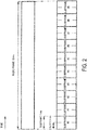
- FIG. 2 is a diagram illustrating a schematic configuration of a radio frame according to an example.
- the horizontal axis is a time axis.
- Each of the radio frames is 10 ms in length.
- each of the radio frames is constituted of 10 subframes.
- Each of the subframes is 1 ms in length and is defined by two consecutive slots.
- Each of the slots is 0.5 ms in length.
- the i-th subframe within a radio frame is constituted of the (2 ⁇ i)-th slot and the (2 ⁇ i+1)-th slot.
- 10 subframes can be used at each interval of 10 ms.
- a frequency to which an LAA cell corresponds may be commonly used by other communication systems and/or other LTE operators.
- the fair frequency sharing technique may be used.
- the fair frequency sharing technique may include Listen-Before-Talk (LBT).
- LBT Listen-Before-Talk
- a radio transmission and/or reception device the base station apparatus 3 or the terminal apparatus 1 transmits a physical channel and a physical signal by using a serving cell (component carrier, channel, medium, frequency), interference power (interference signal, reception power, reception signal, noise power, noise signal) and the like in the above serving cell are measured (detected). Based on the above measurement (detection), whether the above serving cell is in an idle state or in a busy state is identified (detected, expected, determined).
- a serving cell component carrier, channel, medium, frequency
- interference power interference signal, reception power, reception signal, noise power, noise signal
- the radio transmission and/or reception device In a case that the radio transmission and/or reception device identifies the above serving cell is in the idle state based on the above measurement (detection), the radio transmission and/or reception device can transmit a physical channel and a physical signal in the above serving cell. In a case that the radio transmission and/or reception device identifies the above serving cell is in the busy state based on the above measurement (detection), the radio transmission and/or reception device does not transmit a physical channel and a physical signal in the above serving cell.
- the LBT to be performed by the base station apparatus 3 before downlink transmission may be referred to as downlink LBT and the LBT to be performed by the terminal apparatus 1 before uplink transmission may be referred to as uplink LBT.
- An LBT procedure is defined as a mechanism in which the radio transmission and/or reception device applies a Clear Channel Assessment (CCA) check before transmission in a serving cell.
- CCA Clear Channel Assessment
- the radio transmission and/or reception device in order to identify whether a serving cell is in the idle state or in the busy state, performs power detection or signal detection for determining presence or absence of another signal in the above serving cell.
- a definition of the CCA may be equivalent to a definition of the LBT.
- the CCA is also referred to as carrier sense.
- the CCA can use various methods as a method for determining the presence or absence of another signal.
- the presence or absence of another signal may be determined based on whether the interference power in the serving cell exceeds a threshold level or not.
- the presence or absence of another signal may be determined based on whether the reception power of a prescribed signal or channel in the serving cell exceeds a threshold level or not.
- the above threshold level may be defined in advance.
- the above threshold level may be configured based on information/a signal received from other radio transmission and/or reception devices.
- the above threshold level may be determined (configured) based on at least another value (parameter) such as transmit power (maximum transmit power).
- the CCA includes Initial CCA (ICCA, single sensing, LBT category 2, Frame-Based Equipment (FBE)), and Extended CCA (ECCA, multiple sensing, LBT category 3/4, Load-Based Equipment (LBE)).
- ICCA Initial CCA
- FBE Frame-Based Equipment
- ECCA Extended CCA
- LBT category 3/4 Load-Based Equipment
- a physical channel and a physical signal can be transmitted.
- a period in which a CCA check associated with the ICCA is performed is referred to as an ICCA period or an ICCA slot length.
- the ICCA period is 25 microseconds.
- a physical channel and a physical signal can be transmitted.
- a period in which a CCA check associated with the ECCA is performed is referred to as an ECCA period or an ECCA slot length.
- the ECCA period is 9 microseconds.
- the above prescribed number is also referred to as a backoff counter (counter, random number counter, ECCA counter).
- a period in which the CCA check is performed after the serving cell changes from the busy state to the idle state is referred to as a defer period or an ECCA defer period.
- the defer period is 34 microseconds.
- the radio transmission and/or reception device in a case that information (data, buffer, load, traffic) that needs to be transmitted is generated in the idle state of waiting for transmission, determines whether the transmission is needed or not and proceeds to initial CCA.
- the CCA check is performed during an initial CCA period to sense the idle state or the busy state.
- the radio transmission and/or reception device acquires a right to access and proceeds to a transmission operation. Then, whether to actually transmit at that timing or not is determined, and in a case of being determined to transmit, transmission is performed.
- the radio transmission and/or reception device After the transmission, whether any information that needs another transmission is still present (remains) or not is determined. In a case that information that needs another transmission is not present yet (does not remain), the radio transmission and/or reception device returns to the idle state. On the other hand, in a case of determining the busy state as a result of the initial CCA or in a case that the determination of whether any information that needs another transmission is still present (remains) or not results in determination that information that needs another transmission is still present (remains) after transmission, the radio transmission and/or reception device proceeds to the ECCA.
- a counter value N within a range from 0 to q - 1 is randomly generated.
- the radio transmission and/or reception device then senses whether an ECCA defer period is idle or busy. In a case of determining that the ECCA defer period is busy, the radio transmission and/or reception device senses again whether the channel is idle or busy in the ECCA defer period. On the other hand, in a case of determining that the ECCA defer period is idle, then the radio transmission and/or reception device senses the channel (medium) during one ECCA slot duration to determine whether the above channel is idle or busy. In a case of being determined the above channel is idle, the counter value N is decremented by 1.
- the radio transmission and/or reception device returns to the process of sensing the channel in the ECCA defer period again in a case of determining that the above channel is busy.
- the radio transmission and/or reception device determines whether the counter value is 0 or not. In a case that the counter value is 0, the radio transmission and/or reception device proceeds to a transmission process. On the other hand, in a case that the counter value is not 0, the radio transmission and/or reception device senses the channel (medium) during one ECCA slot duration again. Note that a value of a contention window q in a case that the counter value N is generated is updated to a value between X and Y according to a channel state.
- the value of the contention window q is determined based on a power value, a measurement result, and the like that are obtained by channel sensing of the radio transmission and/or reception device.
- a minimum value X and a maximum value Y that are used to determine the value of the contention window q may be parameters configured by a higher layer.
- the ECCA may not necessarily be performed. Specifically, in a case of determining that the channel is busy as a result of the ICCA, the radio transmission and/or reception device may return to the idle state instead of proceeding to the ECCA process. Furthermore, even in a case that, after the transmission, information that needs another transmission is still present, the radio transmission and/or reception device may return to the idle state instead of proceeding to the ECCA process. LBT involving such a process is also referred to as an LBT category 2.
- the transmit power P PRACH for PRACH (random access preamble) transmission is configured based on at least a state variable PREAMBLE_TRANSMISSION_COUNTER.
- the transmit power P PRACH for PRACH (random access preamble) transmission is ramped up based on a state variable PREAMBLE _TRANSMISSION_COUNTER.
- the state variable PREAMBLE _TRANSMISSION _COUNTER is also referred to as the transmission counter.
- the transmit power P PRACH is given by Equation (1) and Equation (2).
- P PRACH min P CMAX , c i , PREAMBLE _ RECEIVED _ TARGET _ POWER + PL c dBm
- P CMAX,c (i) is a maximum transmit power value for a subframe i in a serving cell c. The above maximum transmit power value is also referred to as UE transmit power to be configured.
- PCc is downlink path loss estimation, for the serving cell c. The downlink path loss estimation is calculated by the terminal apparatus 1.
- DELTA_PREAMBLE is a power offset value based on a random access preamble format.
- preambleInitialReceivedTargetPower and powerRampingStep are parameters of a higher layer (RRC layer).
- the base station apparatus 3 may transmit information indicating a parameter of the above higher layer (RRC layer), to the terminal apparatus 1.
- preambleInitialReceivedTargetPower indicates initial transmit power for PRACH (random access preamble) transmission.
- powerRampingStep indicates a step for transmit power to be ramped up based on the transmission counter PREAMBLE_TRANSMISSION_COUNTER. That is, the transmission counter corresponds to the number of times of the transmit power ramped up. Furthermore, by setting the transmission counter to 1, ramp-up of the transmit power is reset. Furthermore, by incrementing the transmission counter by 1, the ramp-up of the transmit power is applied once.
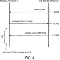
- FIG. 3 is a diagram illustrating an example of the non-contention based random access procedure according to an example.
- the non-contention based random access procedure is started by a PDCCH order.
- the base station apparatus 3 uses a PDCCH to transmit a PDCCH order to the terminal apparatus 1.
- the terminal apparatus 1 uses a PRACH to transmit a random access preamble.
- the base station apparatus 3 transmits a random access response corresponding to the random access preamble transmitted in S302.
- the terminal apparatus 1 regards reception of the random access response succeeds, and regards the random access procedure completes successfully.
- the random access response corresponding to the random access preamble includes a Random Access Preamble IDentifier (RAPID) specifying the random access preamble transmitted in S302. That is, in a case that the random access response includes the RAPID corresponding to the random access preamble transmitted in S302, the terminal apparatus 1 regards reception of the random access response succeeds, and regards the random access procedure completes successfully.
- RAPID Random Access Preamble IDentifier
- the PDCCH order is also referred to as a random access message 0.
- the random access preamble is also referred to as a random access message 1.
- the random access response is also referred to as a random access message 2.
- a DCI format 1A is used for a random access procedure to be started by a PDCCH order.
- the following information may be transmitted by using the DCI format 1A. That is, the PDCCH order may indicate part or all of the following information.
- the terminal apparatus 1 may select an index of the random access preamble to be transmitted in S302.
- the terminal apparatus 1, based on the above PRACH Mask Index, may select a PRACH resource to be used for transmitting the random access preamble in S302.
- the terminal apparatus monitors a PDCCH including RA-RNTI.
- the above RA-RNTI may be given, based on the PRACH resource used for transmitting the random access preamble in S302.
- the PDCCH including the above RA-RNTI includes a downlink grant to be used for scheduling a PDSCH including a random access response.
- the non-contention based random access procedure includes a non-contention based random access procedure type 1 and a non-contention based random access procedure type 2.
- the non-contention based random access procedure type 1 is referred to as an RAP type 1.
- the non-contention based random access procedure type 2 is referred to as an RAP type 2.
- LBT/CCA is not performed immediately before PRACH transmission.
- LBT/CCA is performed immediately before PRACH transmission.
- a management method of a transmission counter in the RAP type 1 is different from a management method of a transmission counter in the RAP type 2.
- the random access preamble is automatically re-transmitted.
- the random access preamble in a case that transmission of a random access preamble is stopped by determining an LBT/CCA period is busy, the random access preamble is automatically re-transmitted.
- the random access preamble in a case that a random access response is not received in a random access response window, or in a case that all random access responses received in a random access response window do not include a RAPID corresponding to a transmitted random access preamble, the random access preamble is not automatically re-transmitted.
- the RAP type 1 may be supported and the RAP type 2 may not necessarily be supported.
- the RAP type 1 may not necessarily be supported and the RAP type 2 may be supported.
- both the RAP type 1 and the RAP type 2 may be supported.
- the base station apparatus 3 may control which of the RAP type 1 and the RAP type 2 is applied, using higher layer signaling (an RRC parameter).
- the terminal apparatus 1, in each of the secondary cell and the LAA cell, based on the higher layer signaling (RRC parameter) received from the base station apparatus 3, may control which of the RAP type 1 and the RAP type 2 is applied.
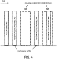
- FIG. 4 is a diagram illustrating an example of the RAP type 1.
- a PDCCH order 400 starts the RAP type 1.
- a transmission counter is set to 1.
- the terminal apparatus determines a PRACH resource to be used for transmitting a random access preamble 402. In a case that a random access response is not received in a random access response window 403, or in a case that all random access responses received in the random access response window 403 do not include a RAPID corresponding to a random access preamble 402, the transmission counter is incremented by 1, and a PRACH resource 404 is selected.
- the terminal apparatus 1 in the case that a random access response is not received in a random access response window 403, or in the case that all random access responses received in the random access response window 403 do not include a RAPID corresponding to the random access preamble 402, the terminal apparatus 1 automatically resumes the transmission of the random access preamble. That is, in the RAP type 1, based on one reception of the PDCCH order, the PRACH (random access preamble) may be transmitted multiple times.
- the terminal apparatus 1 regards that the RAP type 1 completes unsuccessfully, or indicates a random access problem to a higher layer (RRC layer) of the terminal apparatus 1.
- the above prescribed value may be given based on an RRC parameter received from the base station apparatus 3.
- the higher layer (RRC layer) of the terminal apparatus 1 may notify the higher layer (RRC layer) of the base station apparatus 3 of the occurrence of the random access problem.
- the terminal apparatus determines a PRACH resource used for transmitting a random access preamble 404.
- a random access response 406 corresponding to the random access preamble 404 is received in a random access response window 405, reception of the random access response 406 is regarded as success, and the RAP type 1 is regarded to complete successfully.
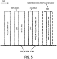
- FIG. 5 is a diagram illustrating an example of the RAP type 2.
- a PDCCH order 500 starts the RAP type 2.
- the terminal apparatus 1 determines periods 501/503 for LBT/CCA, and PRACH resources 502/504 to be used for transmitting a random access preamble. In a case that the terminal apparatus 1 determines the period 501 is busy, the terminal apparatus 1 does not use the PRACH resource 502 to transmit a random access preamble and performs the LBT/CCA in the period 503. In a case that the terminal apparatus 1 determines the period 503 is idle, the terminal apparatus 1 uses the PRACH resource 504 to transmit the random access preamble 504.
- the terminal apparatus 1 In a case that a random access response is not received in the random access response window 505, or in a case that all random access responses received in the random access response window 505 do not include a RAPID corresponding to the random access preamble 504, the terminal apparatus 1, regardless of the value of the transmission counter, regards the RAP type 2 completes unsuccessfully, or indicates a random access problem to a higher layer (RRC layer) of the terminal apparatus 1. That is, in the RAP type 2, in the case that a random access response is not received in the random access response window 505, or in the case that all random access responses received in the random access response window 505 do not include a RAPID corresponding to the random access preamble 504, the terminal apparatus 1 does not automatically resume transmission of the random access preamble. That is, in the RAP type 2, based on one reception of a PDCCH order, a PRACH (random access preamble) is transmitted once.
- RRC layer higher layer
- the terminal apparatus 1 may regard the RAP type 2 completes unsuccessfully, or may indicate a random access problem to the higher layer (RRC layer) of the terminal apparatus 1.
- the terminal apparatus 1 may regard the RAP type 2 completes unsuccessfully, or may indicate a random access problem to the higher layer (RRC layer) of the terminal apparatus 1.
- the base station apparatus 3 may use a PDCCH order (DCI format 1A) to control a transmission counter in the terminal apparatus 1. That is, the base station apparatus 3 may use the PDCCH order (DCI format 1A) to control transmit power P PRACH for PRACH (random access preamble) transmission.
- DCI format 1A PDCCH order
- PRACH random access preamble
- the terminal apparatus 1 may, based on the PDCCH order (DCI format 1A), control the transmission counter. That is, the terminal apparatus 1 may, based on the PDCCH order (DCI format 1A), control the transmit power P PRACH for PRACH (random access preamble) transmission.
- the transmission counter may be set to 1 at a start of the RAP type 2.
- the transmission counter may be incremented by 1 at the start of the RAP type 2.
- the transmission counter may not necessarily be incremented by 1.
- the value of the transmission counter is retained.
- the above prescribed value may be '000000'.
- the terminal apparatus 1 based on a preamble index included in the PDCCH order Y received immediately before reception of the PDCCH order X, may select a random access preamble.
- the transmission counter may be incremented by 1.
- a counter of the transmission counter may be retained.
- the transmission counter may be set to 1 at the start of the RAP type 2.
- the transmission counter may be incremented by 1 at the start of the RAP type 2.
- the transmission counter may not necessarily be incremented by 1. In this case, the value of the transmission counter is retained.
- the transmission counter may be incremented by 1.
- a value of the transmission counter may be retained.
- the terminal apparatus 1 may, based on whether a random access preamble is transmitted or not in any one of (i) information included in the PDCCH order and (ii) the PRACH resource to which the PDCCH order Y received immediately before reception of the PDCCH order X corresponds, perform one of the following process (1) to process (3).
- FIG. 6 is a schematic block diagram illustrating a configuration of the terminal apparatus 1 according to an example.
- the terminal apparatus 1 is constituted to include a radio transmission/reception unit 10 and a higher layer processing unit 14.
- the radio transmission/reception unit 10 is constituted to include an antenna unit 11, a Radio Frequency (RF) unit 12, and a baseband unit 13.
- the higher layer processing unit 14 is constituted to include a medium access control layer processing unit 15, a radio resource control layer processing unit 16 and a transmit power controller 17.
- the radio transmission/reception unit 10 is also referred to as a transmitter, a receiver or a physical layer processing unit.
- the higher layer processing unit 14 outputs uplink data (transport block) generated by a user operation or the like, to the radio transmission/reception unit 10.
- the higher layer processing unit 14 performs processing of the Medium Access Control (MAC) layer, a Packet Data Convergence Protocol (PDCP) layer, a Radio Link Control (RLC) layer, and a Radio Resource Control (RRC) layer.
- MAC Medium Access Control
- PDCP Packet Data Convergence Protocol
- RLC Radio Link Control
- RRC Radio Resource Control
- the medium access control layer processing unit 15 included in the higher layer processing unit 14 performs processing of the Medium Access Control layer.
- the medium access control layer processing unit 15 controls a random access procedure in accordance with the various pieces of configuration information/parameters managed by the radio resource control layer processing unit 16.
- the radio resource control layer processing unit 16 included in the higher layer processing unit 14 performs processing of the Radio Resource Control layer.
- the radio resource control layer processing unit 16 manages the various types of configuration information/parameters of the terminal apparatus 1.
- the radio resource control layer processing unit 16 sets the various types of configuration information/parameters, based on higher layer signaling received from the base station apparatus 3. That is, the radio resource control layer processing unit 16 sets the various types of configuration information/parameters, based on information indicating various types of configuration information/parameters received from the base station apparatus 3.
- the transmit power controller 17 included in the higher layer processing unit 14 configures transmit power for PRACH (random access preamble) transmission.
- the radio transmission/reception unit 10 performs processing of the physical layer, such as modulation, demodulation, coding, and decoding.
- the radio transmission/reception unit 10 demultiplexes, demodulates, and decodes a signal received from the base station apparatus 3, and outputs the information resulting from the decoding to the higher layer processing unit 14.
- the radio transmission/reception unit 10 modulates and codes data to generate a transmit signal, and transmits the transmit signal to the base station apparatus 3.
- the RF unit 12 converts (down-converts) a signal received via the antenna unit 11 into a baseband signal by orthogonal demodulation and removes unnecessary frequency components.
- the RF unit 12 outputs the processed analog signal to the baseband unit.
- the baseband unit 13 converts the analog signal input from the RF unit 12 into a digital signal.
- the baseband unit 13 removes a portion corresponding to a Cyclic Prefix (CP) from the digital signal resulting from the conversion, performs Fast Fourier Transform (FFT) on the signal from which the CP has been removed, and extracts a signal in the frequency domain.
- CP Cyclic Prefix
- FFT Fast Fourier Transform
- the baseband unit 13 performs Inverse Fast Fourier Transform (IFFT) on data, generates an SC-FDMA symbol, attaches a CP to the generated SC-FDMA symbol, generates a baseband digital signal, and converts the baseband digital signal into an analog signal.
- IFFT Inverse Fast Fourier Transform
- the baseband unit 13 outputs the analog signal resulting from the conversion, to the RF unit 12.
- the RF unit 12 removes unnecessary frequency components from the analog signal input from the baseband unit 13 by using a low-pass filter, up-converts the analog signal into a signal of a carrier frequency, and transmits the final result via the antenna unit 11. Furthermore, the RF unit 12 amplifies power. Furthermore, the RF unit 12 may have a function of controlling transmit power. The RF unit 12 is also referred to as a transmit power controller.
- FIG. 7 is a schematic block diagram illustrating a configuration of the base station apparatus 3 according to an example.
- the base station apparatus 3 is constituted to include a radio transmission/reception unit 30 and a higher layer processing unit 34.
- the radio transmission/reception unit 30 is constituted to include an antenna unit 31, an RF unit 32, and a baseband unit 33.
- the higher layer processing unit 34 is constituted to include a medium access control layer processing unit 35 and a radio resource control layer processing unit 36.
- the radio transmission/reception unit 30 is also referred to as a transmitter, a receiver or a physical layer processing unit.
- the higher layer processing unit 34 performs processing of the Medium Access Control (MAC) layer, the Packet Data Convergence Protocol (PDCP) layer, the Radio Link Control (RLC) layer, and the Radio Resource Control (RRC) layer.
- MAC Medium Access Control
- PDCP Packet Data Convergence Protocol
- RLC Radio Link Control
- RRC Radio Resource Control
- the medium access control layer processing unit 35 included in the higher layer processing unit 34 performs processing of the Medium Access Control layer.
- the medium access control layer processing unit 35 controls a random access procedure in accordance with the various pieces of configuration information/parameters managed by the radio resource control layer processing unit 36.
- the radio resource control layer processing unit 36 included in the higher layer processing unit 34 performs processing of the Radio Resource Control layer.
- the radio resource control layer processing unit 36 generates, or acquires from a higher node, downlink data (transport block) arranged on a physical downlink shared channel, system information, an RRC message, a MAC Control Element (CE), and the like, and outputs the generated or acquired data to the radio transmission/reception unit 30.
- the radio resource control layer processing unit 36 manages various types of configuration information/parameters for each of the terminal apparatuses 1.
- the radio resource control layer processing unit 36 may set various types of configuration information/parameters for each of the terminal apparatuses 1 via the higher layer signaling. In other words, the radio resource control layer processing unit 36 transmits/broadcasts information indicating various types of configuration information/parameters.
- the functionality of the radio transmission/reception unit 30 is similar to that of the radio transmission/reception unit 10, and hence description thereof is omitted.
- Each of the units having the reference signs 10 to 16 included in the terminal apparatus 1 may be configured as a circuit.
- Each of the units having the reference signs 30 to 36 included in the base station apparatus 3 may be configured as a circuit.
- a terminal apparatus can perform a random access procedure efficiently. Further, a base station apparatus can perform a random access procedure efficiently.
- a program running on each of the base station apparatus 3 and the terminal apparatus 1 may serve as a program that controls a Central Processing Unit (CPU) and the like (a program for causing a computer to operate) in such a manner as to enable the functionalities according to the above-described embodiment of an aspect of the present invention.
- the information handled in these apparatuses is temporarily stored in a Random Access Memory (RAM) while being processed. Thereafter, the information is stored in various types of Read Only Memory (ROM) such as a flash ROM and a Hard Disk Drive (HDD), and when necessary, is read by the CPU to be modified or rewritten.
- ROM Read Only Memory
- HDD Hard Disk Drive
- the terminal apparatus 1 and the base station apparatus 3 may be partially achieved by a computer.
- this configuration may be enabled by recording a program for enabling such control functions on a computer-readable recording medium and causing a computer system to read the program recorded on the recording medium for execution.
- the "computer system” refers to a computer system built into the terminal apparatus 1 or the base station apparatus 3, and the computer system includes an OS and hardware components such as a peripheral device.
- the "computer-readable recording medium” refers to a portable medium such as a flexible disk, a magneto-optical disk, a ROM, and a CD-ROM, and a storage device such as a hard disk built into the computer system.
- the "computer-readable recording medium” may include a medium that dynamically retains the program for a short period of time, such as a communication line that is used to transmit the program over a network such as the Internet or over a communication line such as a telephone line, and a medium that retains, in that case, the program for a fixed period of time, such as a volatile memory within the computer system which functions as a server or a client.
- the program may be configured to enable some of the functions described above, and also may be configured to be capable of enabling the functions described above in combination with a program already recorded in the computer system.
- the base station apparatus 3 is achieved as an aggregation (a device group) constituted of multiple devices.
- Each of the devices constituting such a device group may include some or all portions of each function or each functional block of the base station apparatus 3 according to an example.
- the device group may include a series of general functions or functional blocks of the base station apparatus 3.
- the terminal apparatus 1 according to an example can also communicate with the base station apparatus as the aggregation.
- the base station apparatus 3 may serve as an Evolved Universal Terrestrial Radio Access Network (EUTRAN). Furthermore, the base station apparatus 3 according to an example may have some or all portions of the functions of a node higher than an eNodeB.
- EUTRAN Evolved Universal Terrestrial Radio Access Network
- each of the terminal apparatus 1 and the base station apparatus 3 may be achieved as an LSI which is a typical integrated circuit or may be achieved as a chip set.
- Each of the functional blocks of the terminal apparatus 1 and the base station apparatus 3 may be individually achieved as a chip, or some or all of the functional blocks may be integrated into a chip.
- a circuit integration technique is not limited to the LSI, and may be achieved with a dedicated circuit or a general-purpose processor.
- a circuit integration technology with which an LSI is replaced appears it is also possible to use an integrated circuit based on the technology.
- the terminal apparatus has been described as an example of a communication device, but the present invention is not limited to such a terminal apparatus, and is applicable to a terminal apparatus or a communication device of a fixed-type or a stationary-type electronic apparatus installed indoors or outdoors, for example, such as an Audio-Video (AV) apparatus, a kitchen apparatus, a cleaning or washing machine, an air-conditioning apparatus, office equipment, a vending machine, and other household apparatuses.
- AV Audio-Video
Landscapes
- Engineering & Computer Science (AREA)
- Signal Processing (AREA)
- Computer Networks & Wireless Communication (AREA)
- Mobile Radio Communication Systems (AREA)
Claims (8)
- Un appareil terminal (1, 1A, 1B, 1C) qui communique avec un appareil de station de base (3) en utilisant de multiples cellules de desserte incluant une cellule primaire et une ou plusieurs cellules secondaires, comprenant :une unité de traitement de couche de commande d'accès au support (15) configurée pour initier une procédure d'accès aléatoire pour une cellule secondaire sur la base d'une réception unique d'un ordre de canal de commande de liaison descendante physique (Physical Downlink Control CHannel), PDCCH ;un émetteur (10) configuré pour transmettre un premier préambule d'accès aléatoire ; etun récepteur (10) configuré pour recevoir une réponse d'accès aléatoire,sachant quel'émetteur (10) est en outre configuré pour transmettre un deuxième préambule d'accès aléatoire après que l'émetteur (10) a transmis le premier préambule d'accès aléatoire,l'unité de traitement de couche de commande d'accès au support (15), dans un cas où la réception de la réponse d'accès aléatoire est considérée comme non réussie et où le premier préambule d'accès aléatoire a été transmis sur la cellule secondaire, détermine s'il faut transmettre le deuxième préambule d'accès aléatoire sur la base de la réception unique de l'ordre PDCCH, sur la base d'une configuration d'une couche supérieure, et quel'émetteur (10) est en outre configuré pour reprendre, sur la base d'un deuxième ordre PDCCH, la transmission du préambule d'accès aléatoire pour transmettre le deuxième préambule d'accès aléatoire, dans un cas où l'unité de traitement de couche de commande d'accès au support (15) détermine, sur la base de la configuration, que l'émetteur (10) ne transmet pas le deuxième préambule d'accès aléatoire sur la base de la réception unique.
- L'appareil terminal (1, 1A, 1B, 1C) d'après la revendication 1, sachant que
dans un cas où la réception de la réponse d'accès aléatoire est considérée comme non réussie et le premier préambule d'accès aléatoire a été transmis sur la cellule primaire, l'unité de traitement de couche de commande d'accès au support (15) détermine que l'émetteur (10) transmet le deuxième préambule d'accès aléatoire sur la base de la réception unique de l'ordre PDCCH. - L'appareil terminal (1, 1A, 1B, 1C) d'après la revendication 2, sachant que la configuration de la couche supérieure est une configuration de couche supérieure pour la cellule secondaire qui est l'une des configurations de couche supérieure respectives pour la une ou les multiples cellules secondaires.
- Un procédé de communication utilisé pour un appareil terminal (1, 1A, 1B, 1C) qui communique avec un appareil de station de base (3) en utilisant de multiples cellules de desserte incluant une cellule primaire et une ou plusieurs cellules secondaires, comprenant les étapes consistant à :initier une procédure d'accès aléatoire pour une cellule secondaire sur la base d'une réception unique d'un ordre de canal de commande de liaison descendante physique (Physical Downlink Control CHannel), PDCCH ;transmettre un premier préambule d'accès aléatoire ;déterminer, sur la base d'une configuration d'une couche supérieure, s'il faut transmettre un deuxième préambule d'accès aléatoire sur la base de la réception unique de l'ordre PDCCH, dans le cas où la réception d'une réponse d'accès aléatoire est considérée comme non réussie et où le premier préambule d'accès aléatoire a été transmis sur la cellule secondaire ; et àtransmettre le deuxième préambule d'accès aléatoire après avoir transmis le premier préambule d'accès aléatoire, sachant quedans un cas où l'appareil terminal (1, 1A, 1B, 1C) détermine, sur la base de la configuration, que l'appareil terminal (1, 1A, 1B, 1C) ne transmet pas le deuxième préambule d'accès aléatoire sur la base de la réception unique, le deuxième préambule d'accès aléatoire est transmis sur la base d'un deuxième ordre PDCCH utilisé pour reprendre la transmission du préambule d'accès aléatoire.
- Le procédé de communication d'après la revendication 4, comprenant en outre l'étape consistant à :
déterminer que l'appareil terminal (1, 1A, 1B, 1C) transmet le deuxième préambule d'accès aléatoire sur la base de la réception unique de l'ordre PDCCH, dans un cas où (a) la réception de la réponse d'accès aléatoire est considérée comme non réussie et où (b) le premier préambule d'accès aléatoire a été transmis sur la cellule primaire. - Le procédé de communication d'après la revendication 5, sachant que la configuration de la couche supérieure est une configuration de couche supérieure pour la cellule secondaire qui est l'une des configurations de couche supérieure respectives pour la une ou plusieurs cellules secondaires.
- Un appareil de station de base (3) qui communique avec un appareil terminal (1, 1A, 1B, 1C) en utilisant de multiples cellules de desserte incluant une cellule primaire et une ou plusieurs cellules secondaires, comprenant :un émetteur (30) configuré pour transmettre, vers l'appareil terminal (1, 1A, 1B, 1C), un ordre de canal de commande de liaison descendante physique (Physical Downlink Control CHannel), PDCCH, sachant que l'ordre PDCCH amène l'appareil terminal (1, 1A, 1B, 1C) à initier une procédure d'accès aléatoire pour une cellule secondaire sur la base d'une réception unique de l'ordre PDCCH ; etun récepteur (30) configuré pour recevoir, de la part de l'appareil terminal (1, 1A, 1B, 1C), un premier préambule d'accès aléatoire,sachant que l'émetteur (30) est en outre configuré pour transmettre une réponse d'accès aléatoire à l'appareil terminal (1, 1A, 1B, 1C),l'émetteur (30) est en outre configuré pour transmettre, à l'appareil terminal (1, 1A, 1B, 1C), une configuration d'une couche supérieure, sachant que la configuration amène l'appareil terminal (1, 1A, 1B, 1C) à déterminer, sur la base de la configuration, s'il doit transmettre un deuxième préambule d'accès aléatoire sur la base de la réception unique de l'ordre PDCCH dans un cas où (a) la réception de la réponse d'accès aléatoire est considérée comme non réussie et où (b) l'appareil terminal (1, 1A, 1B, 1C) a transmis le premier préambule d'accès aléatoire sur la cellule secondaire,l'émetteur (30) est en outre configuré pour transmettre un deuxième ordre PDCCH à l'appareil terminal (1, 1A, 1B, 1C), sachant que, dans un cas où l'appareil terminal (1, 1A, 1B, 1C) détermine, sur la base de la configuration, que l'appareil terminal (1, 1A, 1B, 1C) ne transmet pas le deuxième préambule d'accès aléatoire sur la base de la réception unique, le deuxième ordre PDCCH est utilisé pour amener l'appareil terminal (1, 1A, 1B, 1C) à reprendre la transmission du préambule d'accès aléatoire pour transmettre le deuxième préambule d'accès aléatoire, et quele récepteur (30) est en outre configuré pour recevoir le deuxième préambule d'accès aléatoire après avoir reçu le premier préambule d'accès aléatoire.
- Un procédé de communication utilisé pour un appareil de station de base (3) qui communique avec un appareil terminal (1, 1A, 1B, 1C) en utilisant de multiples cellules de desserte incluant une cellule primaire et une ou plusieurs cellules secondaires, comprenant les étapes consistant à :transmettre, à l'appareil terminal (1, 1A, 1B, 1C), un ordre de canal de commande de liaison descendante physique (Physical Downlink Control CHannel), PDCCH, sachant que l'ordre PDCCH amène l'appareil terminal (1, 1A, 1B, 1C) à initier une procédure d'accès aléatoire pour une cellule secondaire sur la base d'une réception unique de l'ordre PDCCH ;recevoir, de la part de l'appareil terminal (1, 1A, 1B, 1C), un premier préambule d'accès aléatoire ;transmettre une réponse d'accès aléatoire à l'appareil terminal (1, 1A, 1B, 1C) ;transmettre, au dispositif terminal (1, 1A, 1B, 1C), une configuration d'une couche supérieure, sachant que la configuration amène l'appareil terminal (1, 1A, 1B, 1C) à déterminer, sur la base de la configuration, s'il faut transmettre un deuxième préambule d'accès aléatoire sur la base de la réception unique de l'ordre PDCCH dans le cas où (a) la réception de la réponse d'accès aléatoire est considérée comme non réussie et où (b) l'appareil terminal (1, 1A, 1B, 1C) a transmis le premier préambule d'accès aléatoire sur la cellule secondaire ;transmettre un deuxième ordre PDCCH à l'appareil terminal (1, 1A, 1B, 1C), sachant que, dans un cas où l'appareil terminal (1, 1A, 1B, 1C) détermine, sur la base de la configuration, que l'appareil terminal (1, 1A, 1B, 1C) ne transmet pas le deuxième préambule d'accès aléatoire sur la base de la réception unique, le deuxième ordre PDCCH est utilisé pour amener l'appareil terminal (1, 1A, 1B, 1C) à reprendre la transmission du préambule d'accès aléatoire pour transmettre le deuxième préambule d'accès aléatoire ; etrecevoir le deuxième préambule d'accès aléatoire après avoir reçu le premier préambule d'accès aléatoire.
Applications Claiming Priority (2)
| Application Number | Priority Date | Filing Date | Title |
|---|---|---|---|
| JP2016084269A JP2019110351A (ja) | 2016-04-20 | 2016-04-20 | 端末装置、基地局装置、通信方法、および、集積回路 |
| PCT/JP2017/007851 WO2017183312A1 (fr) | 2016-04-20 | 2017-02-28 | Dispositif terminal et procédé de communication |
Publications (3)
| Publication Number | Publication Date |
|---|---|
| EP3448095A1 EP3448095A1 (fr) | 2019-02-27 |
| EP3448095A4 EP3448095A4 (fr) | 2019-11-20 |
| EP3448095B1 true EP3448095B1 (fr) | 2021-07-28 |
Family
ID=60116776
Family Applications (1)
| Application Number | Title | Priority Date | Filing Date |
|---|---|---|---|
| EP17785657.2A Active EP3448095B1 (fr) | 2016-04-20 | 2017-02-28 | Dispositif terminal, dispositif de station de base et procédés de communication correspendants |
Country Status (8)
| Country | Link |
|---|---|
| US (1) | US10716144B2 (fr) |
| EP (1) | EP3448095B1 (fr) |
| JP (1) | JP2019110351A (fr) |
| KR (1) | KR102762191B1 (fr) |
| CN (1) | CN108886753B (fr) |
| CA (1) | CA3021275A1 (fr) |
| PT (1) | PT3448095T (fr) |
| WO (1) | WO2017183312A1 (fr) |
Families Citing this family (4)
| Publication number | Priority date | Publication date | Assignee | Title |
|---|---|---|---|---|
| WO2017183309A1 (fr) * | 2016-04-20 | 2017-10-26 | シャープ株式会社 | Dispositif terminal, dispositif de station de base et procédé de communication |
| JP7413349B2 (ja) * | 2018-08-31 | 2024-01-15 | 富士通株式会社 | ランダムアクセス方法、データ受信方法及びその装置、通信システム |
| KR102656607B1 (ko) * | 2018-09-07 | 2024-04-12 | 삼성전자주식회사 | 비면허 대역에서의 다중 채널을 이용한 통신 방법 및 장치 |
| US20240215074A1 (en) * | 2021-05-10 | 2024-06-27 | Ntt Docomo, Inc. | Terminal and communication method |
Family Cites Families (11)
| Publication number | Priority date | Publication date | Assignee | Title |
|---|---|---|---|---|
| KR101514841B1 (ko) * | 2007-08-10 | 2015-04-23 | 엘지전자 주식회사 | 효율적인 랜덤 액세스 재시도를 수행하는 방법 |
| KR100968020B1 (ko) * | 2008-06-18 | 2010-07-08 | 엘지전자 주식회사 | 랜덤 액세스 절차를 수행하는 방법 및 그 단말 |
| US8717908B2 (en) * | 2009-11-02 | 2014-05-06 | Optis Cellular Technology, Llc | Component carrier selection method and apparatus for random access attempts in a communications network |
| WO2013069994A1 (fr) * | 2011-11-08 | 2013-05-16 | 엘지전자 주식회사 | Procédé et dispositif de réglage de puissance d'émission de liaison montante dans un système de communication sans fil |
| CN102595634B (zh) * | 2012-01-31 | 2015-07-15 | 普天信息技术研究院有限公司 | 一种载波聚合中接收随机接入响应信息的方法 |
| US9414409B2 (en) * | 2012-02-06 | 2016-08-09 | Samsung Electronics Co., Ltd. | Method and apparatus for transmitting/receiving data on multiple carriers in mobile communication system |
| EP2849476B1 (fr) * | 2012-05-11 | 2017-12-20 | Kyocera Corporation | Procédé de gestion de communications, terminal d'utilisateur et processeur |
| CN105794297B (zh) * | 2013-12-05 | 2019-03-12 | Lg 电子株式会社 | 执行用于会聚增强的随机接入过程的方法和装置 |
| CN104780617B (zh) * | 2014-01-09 | 2019-09-17 | 中兴通讯股份有限公司 | 一种非竞争随机接入方法、节点设备及系统 |
| WO2016048870A1 (fr) * | 2014-09-25 | 2016-03-31 | Sharp Laboratories Of America, Inc. | Réduction du temps de latence pour la commutation de mode dans les communications de liaison latérale |
| WO2016163845A1 (fr) * | 2015-04-10 | 2016-10-13 | Lg Electronics Inc. | Procédé et appareil pour exécuter un procédé d'accès aléatoire en fonction d'un conflit plutôt qu'un procédé d'accès aléatoire sans conflit dans un système de communication sans fil |
-
2016
- 2016-04-20 JP JP2016084269A patent/JP2019110351A/ja active Pending
-
2017
- 2017-02-28 PT PT177856572T patent/PT3448095T/pt unknown
- 2017-02-28 EP EP17785657.2A patent/EP3448095B1/fr active Active
- 2017-02-28 CA CA3021275A patent/CA3021275A1/fr active Pending
- 2017-02-28 US US16/095,313 patent/US10716144B2/en active Active
- 2017-02-28 CN CN201780017986.5A patent/CN108886753B/zh active Active
- 2017-02-28 KR KR1020187021803A patent/KR102762191B1/ko active Active
- 2017-02-28 WO PCT/JP2017/007851 patent/WO2017183312A1/fr not_active Ceased
Also Published As
| Publication number | Publication date |
|---|---|
| KR20180134843A (ko) | 2018-12-19 |
| EP3448095A1 (fr) | 2019-02-27 |
| JP2019110351A (ja) | 2019-07-04 |
| US10716144B2 (en) | 2020-07-14 |
| PT3448095T (pt) | 2021-09-20 |
| EP3448095A4 (fr) | 2019-11-20 |
| CN108886753A (zh) | 2018-11-23 |
| CN108886753B (zh) | 2021-12-14 |
| CA3021275A1 (fr) | 2017-10-26 |
| KR102762191B1 (ko) | 2025-02-07 |
| WO2017183312A1 (fr) | 2017-10-26 |
| US20190141743A1 (en) | 2019-05-09 |
Similar Documents
| Publication | Publication Date | Title |
|---|---|---|
| EP3448094B1 (fr) | Dispositif terminal, dispositif de station de base et procédé de communication | |
| US10932207B2 (en) | Terminal apparatus, base station apparatus, communication method, and integrated circuit | |
| EP3541139B1 (fr) | Appareil terminal, appareil de station de base, procédé de communication et circuit intégré | |
| US10863540B2 (en) | Terminal apparatus, communication method, and integrated circuit | |
| JP6682000B2 (ja) | アップリンク制御チャネル上で送信をするためのパラメータを決定するための方法 | |
| EP2353264B1 (fr) | Procédé dans un système de réseau de communication | |
| CN112272369B (zh) | 基站、用户设备、其方法及计算机可读介质 | |
| US20180263063A1 (en) | Numerology dependent random access timing | |
| JP7520883B2 (ja) | ランダムアクセス方法、装置及び通信システム | |
| EP3499829B1 (fr) | Dispositif terminal, dispositif station de base, procédé de communication, et circuit intégré | |
| JP2018511236A (ja) | 物理ランダムアクセスチャネル送信のための繰返しレベルカバレージ拡張技法 | |
| EP3448095B1 (fr) | Dispositif terminal, dispositif de station de base et procédés de communication correspendants | |
| WO2019029695A1 (fr) | Procédé et appareil de régulation de puissance | |
| US20250133600A1 (en) | Wireless communication method and apparatus | |
| WO2016159372A1 (fr) | Système de communication sans fil, dispositif terminal, dispositif de station de base, procédé de communication sans fil et circuit intégré | |
| CN109983795B (zh) | 用于促进数据传输的方法和装置 | |
| CN119678587A (zh) | 无线通信方法、终端设备以及网络设备 |
Legal Events
| Date | Code | Title | Description |
|---|---|---|---|
| STAA | Information on the status of an ep patent application or granted ep patent |
Free format text: STATUS: THE INTERNATIONAL PUBLICATION HAS BEEN MADE |
|
| PUAI | Public reference made under article 153(3) epc to a published international application that has entered the european phase |
Free format text: ORIGINAL CODE: 0009012 |
|
| STAA | Information on the status of an ep patent application or granted ep patent |
Free format text: STATUS: REQUEST FOR EXAMINATION WAS MADE |
|
| 17P | Request for examination filed |
Effective date: 20181018 |
|
| AK | Designated contracting states |
Kind code of ref document: A1 Designated state(s): AL AT BE BG CH CY CZ DE DK EE ES FI FR GB GR HR HU IE IS IT LI LT LU LV MC MK MT NL NO PL PT RO RS SE SI SK SM TR |
|
| AX | Request for extension of the european patent |
Extension state: BA ME |
|
| DAV | Request for validation of the european patent (deleted) | ||
| DAX | Request for extension of the european patent (deleted) | ||
| RAP1 | Party data changed (applicant data changed or rights of an application transferred) |
Owner name: FG INNOVATION COMPANY LIMITED Owner name: SHARP KABUSHIKI KAISHA |
|
| A4 | Supplementary search report drawn up and despatched |
Effective date: 20191022 |
|
| RIC1 | Information provided on ipc code assigned before grant |
Ipc: H04J 99/00 20090101ALI20191016BHEP Ipc: H04J 11/00 20060101ALI20191016BHEP Ipc: H04W 72/04 20090101ALI20191016BHEP Ipc: H04W 52/50 20090101AFI20191016BHEP Ipc: H04W 74/08 20090101ALI20191016BHEP |
|
| GRAP | Despatch of communication of intention to grant a patent |
Free format text: ORIGINAL CODE: EPIDOSNIGR1 |
|
| STAA | Information on the status of an ep patent application or granted ep patent |
Free format text: STATUS: GRANT OF PATENT IS INTENDED |
|
| INTG | Intention to grant announced |
Effective date: 20210222 |
|
| GRAS | Grant fee paid |
Free format text: ORIGINAL CODE: EPIDOSNIGR3 |
|
| GRAA | (expected) grant |
Free format text: ORIGINAL CODE: 0009210 |
|
| STAA | Information on the status of an ep patent application or granted ep patent |
Free format text: STATUS: THE PATENT HAS BEEN GRANTED |
|
| AK | Designated contracting states |
Kind code of ref document: B1 Designated state(s): AL AT BE BG CH CY CZ DE DK EE ES FI FR GB GR HR HU IE IS IT LI LT LU LV MC MK MT NL NO PL PT RO RS SE SI SK SM TR |
|
| REG | Reference to a national code |
Ref country code: GB Ref legal event code: FG4D |
|
| REG | Reference to a national code |
Ref country code: CH Ref legal event code: EP |
|
| REG | Reference to a national code |
Ref country code: AT Ref legal event code: REF Ref document number: 1415904 Country of ref document: AT Kind code of ref document: T Effective date: 20210815 |
|
| REG | Reference to a national code |
Ref country code: IE Ref legal event code: FG4D |
|
| REG | Reference to a national code |
Ref country code: DE Ref legal event code: R096 Ref document number: 602017042979 Country of ref document: DE |
|
| REG | Reference to a national code |
Ref country code: PT Ref legal event code: SC4A Ref document number: 3448095 Country of ref document: PT Date of ref document: 20210920 Kind code of ref document: T Free format text: AVAILABILITY OF NATIONAL TRANSLATION Effective date: 20210913 |
|
| REG | Reference to a national code |
Ref country code: LT Ref legal event code: MG9D |
|
| REG | Reference to a national code |
Ref country code: NL Ref legal event code: MP Effective date: 20210728 |
|
| PG25 | Lapsed in a contracting state [announced via postgrant information from national office to epo] |
Ref country code: BG Free format text: LAPSE BECAUSE OF FAILURE TO SUBMIT A TRANSLATION OF THE DESCRIPTION OR TO PAY THE FEE WITHIN THE PRESCRIBED TIME-LIMIT Effective date: 20211028 Ref country code: LT Free format text: LAPSE BECAUSE OF FAILURE TO SUBMIT A TRANSLATION OF THE DESCRIPTION OR TO PAY THE FEE WITHIN THE PRESCRIBED TIME-LIMIT Effective date: 20210728 Ref country code: FI Free format text: LAPSE BECAUSE OF FAILURE TO SUBMIT A TRANSLATION OF THE DESCRIPTION OR TO PAY THE FEE WITHIN THE PRESCRIBED TIME-LIMIT Effective date: 20210728 Ref country code: ES Free format text: LAPSE BECAUSE OF FAILURE TO SUBMIT A TRANSLATION OF THE DESCRIPTION OR TO PAY THE FEE WITHIN THE PRESCRIBED TIME-LIMIT Effective date: 20210728 Ref country code: NO Free format text: LAPSE BECAUSE OF FAILURE TO SUBMIT A TRANSLATION OF THE DESCRIPTION OR TO PAY THE FEE WITHIN THE PRESCRIBED TIME-LIMIT Effective date: 20211028 Ref country code: NL Free format text: LAPSE BECAUSE OF FAILURE TO SUBMIT A TRANSLATION OF THE DESCRIPTION OR TO PAY THE FEE WITHIN THE PRESCRIBED TIME-LIMIT Effective date: 20210728 Ref country code: SE Free format text: LAPSE BECAUSE OF FAILURE TO SUBMIT A TRANSLATION OF THE DESCRIPTION OR TO PAY THE FEE WITHIN THE PRESCRIBED TIME-LIMIT Effective date: 20210728 Ref country code: RS Free format text: LAPSE BECAUSE OF FAILURE TO SUBMIT A TRANSLATION OF THE DESCRIPTION OR TO PAY THE FEE WITHIN THE PRESCRIBED TIME-LIMIT Effective date: 20210728 Ref country code: HR Free format text: LAPSE BECAUSE OF FAILURE TO SUBMIT A TRANSLATION OF THE DESCRIPTION OR TO PAY THE FEE WITHIN THE PRESCRIBED TIME-LIMIT Effective date: 20210728 |
|
| PG25 | Lapsed in a contracting state [announced via postgrant information from national office to epo] |
Ref country code: PL Free format text: LAPSE BECAUSE OF FAILURE TO SUBMIT A TRANSLATION OF THE DESCRIPTION OR TO PAY THE FEE WITHIN THE PRESCRIBED TIME-LIMIT Effective date: 20210728 Ref country code: LV Free format text: LAPSE BECAUSE OF FAILURE TO SUBMIT A TRANSLATION OF THE DESCRIPTION OR TO PAY THE FEE WITHIN THE PRESCRIBED TIME-LIMIT Effective date: 20210728 Ref country code: GR Free format text: LAPSE BECAUSE OF FAILURE TO SUBMIT A TRANSLATION OF THE DESCRIPTION OR TO PAY THE FEE WITHIN THE PRESCRIBED TIME-LIMIT Effective date: 20211029 |
|
| PG25 | Lapsed in a contracting state [announced via postgrant information from national office to epo] |
Ref country code: DK Free format text: LAPSE BECAUSE OF FAILURE TO SUBMIT A TRANSLATION OF THE DESCRIPTION OR TO PAY THE FEE WITHIN THE PRESCRIBED TIME-LIMIT Effective date: 20210728 |
|
| REG | Reference to a national code |
Ref country code: DE Ref legal event code: R097 Ref document number: 602017042979 Country of ref document: DE |
|
| PG25 | Lapsed in a contracting state [announced via postgrant information from national office to epo] |
Ref country code: SM Free format text: LAPSE BECAUSE OF FAILURE TO SUBMIT A TRANSLATION OF THE DESCRIPTION OR TO PAY THE FEE WITHIN THE PRESCRIBED TIME-LIMIT Effective date: 20210728 Ref country code: SK Free format text: LAPSE BECAUSE OF FAILURE TO SUBMIT A TRANSLATION OF THE DESCRIPTION OR TO PAY THE FEE WITHIN THE PRESCRIBED TIME-LIMIT Effective date: 20210728 Ref country code: RO Free format text: LAPSE BECAUSE OF FAILURE TO SUBMIT A TRANSLATION OF THE DESCRIPTION OR TO PAY THE FEE WITHIN THE PRESCRIBED TIME-LIMIT Effective date: 20210728 Ref country code: EE Free format text: LAPSE BECAUSE OF FAILURE TO SUBMIT A TRANSLATION OF THE DESCRIPTION OR TO PAY THE FEE WITHIN THE PRESCRIBED TIME-LIMIT Effective date: 20210728 Ref country code: CZ Free format text: LAPSE BECAUSE OF FAILURE TO SUBMIT A TRANSLATION OF THE DESCRIPTION OR TO PAY THE FEE WITHIN THE PRESCRIBED TIME-LIMIT Effective date: 20210728 Ref country code: AL Free format text: LAPSE BECAUSE OF FAILURE TO SUBMIT A TRANSLATION OF THE DESCRIPTION OR TO PAY THE FEE WITHIN THE PRESCRIBED TIME-LIMIT Effective date: 20210728 |
|
| PLBE | No opposition filed within time limit |
Free format text: ORIGINAL CODE: 0009261 |
|
| STAA | Information on the status of an ep patent application or granted ep patent |
Free format text: STATUS: NO OPPOSITION FILED WITHIN TIME LIMIT |
|
| 26N | No opposition filed |
Effective date: 20220429 |
|
| PG25 | Lapsed in a contracting state [announced via postgrant information from national office to epo] |
Ref country code: IT Free format text: LAPSE BECAUSE OF FAILURE TO SUBMIT A TRANSLATION OF THE DESCRIPTION OR TO PAY THE FEE WITHIN THE PRESCRIBED TIME-LIMIT Effective date: 20210728 |
|
| PG25 | Lapsed in a contracting state [announced via postgrant information from national office to epo] |
Ref country code: MC Free format text: LAPSE BECAUSE OF FAILURE TO SUBMIT A TRANSLATION OF THE DESCRIPTION OR TO PAY THE FEE WITHIN THE PRESCRIBED TIME-LIMIT Effective date: 20210728 |
|
| REG | Reference to a national code |
Ref country code: CH Ref legal event code: PL |
|
| REG | Reference to a national code |
Ref country code: BE Ref legal event code: MM Effective date: 20220228 |
|
| PG25 | Lapsed in a contracting state [announced via postgrant information from national office to epo] |
Ref country code: LU Free format text: LAPSE BECAUSE OF NON-PAYMENT OF DUE FEES Effective date: 20220228 |
|
| REG | Reference to a national code |
Ref country code: AT Ref legal event code: UEP Ref document number: 1415904 Country of ref document: AT Kind code of ref document: T Effective date: 20210728 |
|
| PG25 | Lapsed in a contracting state [announced via postgrant information from national office to epo] |
Ref country code: LI Free format text: LAPSE BECAUSE OF NON-PAYMENT OF DUE FEES Effective date: 20220228 Ref country code: IE Free format text: LAPSE BECAUSE OF NON-PAYMENT OF DUE FEES Effective date: 20220228 Ref country code: CH Free format text: LAPSE BECAUSE OF NON-PAYMENT OF DUE FEES Effective date: 20220228 |
|
| PG25 | Lapsed in a contracting state [announced via postgrant information from national office to epo] |
Ref country code: BE Free format text: LAPSE BECAUSE OF NON-PAYMENT OF DUE FEES Effective date: 20220228 |
|
| REG | Reference to a national code |
Ref country code: DE Ref legal event code: R081 Ref document number: 602017042979 Country of ref document: DE Owner name: FG INNOVATION CO. LTD., TUEN MUN, HK Free format text: FORMER OWNERS: FG INNOVATION COMPANY LIMITED, HONG KONG, HK; SHARP KABUSHIKI KAISHA, SAKAI-CITY, OSAKA, JP Ref country code: DE Ref legal event code: R081 Ref document number: 602017042979 Country of ref document: DE Owner name: SHARP KABUSHIKI KAISHA, SAKAI CITY, JP Free format text: FORMER OWNERS: FG INNOVATION COMPANY LIMITED, HONG KONG, HK; SHARP KABUSHIKI KAISHA, SAKAI-CITY, OSAKA, JP |
|
| PG25 | Lapsed in a contracting state [announced via postgrant information from national office to epo] |
Ref country code: HU Free format text: LAPSE BECAUSE OF FAILURE TO SUBMIT A TRANSLATION OF THE DESCRIPTION OR TO PAY THE FEE WITHIN THE PRESCRIBED TIME-LIMIT; INVALID AB INITIO Effective date: 20170228 |
|
| PG25 | Lapsed in a contracting state [announced via postgrant information from national office to epo] |
Ref country code: MK Free format text: LAPSE BECAUSE OF FAILURE TO SUBMIT A TRANSLATION OF THE DESCRIPTION OR TO PAY THE FEE WITHIN THE PRESCRIBED TIME-LIMIT Effective date: 20210728 Ref country code: CY Free format text: LAPSE BECAUSE OF FAILURE TO SUBMIT A TRANSLATION OF THE DESCRIPTION OR TO PAY THE FEE WITHIN THE PRESCRIBED TIME-LIMIT Effective date: 20210728 |
|
| PG25 | Lapsed in a contracting state [announced via postgrant information from national office to epo] |
Ref country code: TR Free format text: LAPSE BECAUSE OF FAILURE TO SUBMIT A TRANSLATION OF THE DESCRIPTION OR TO PAY THE FEE WITHIN THE PRESCRIBED TIME-LIMIT Effective date: 20210728 |
|
| PG25 | Lapsed in a contracting state [announced via postgrant information from national office to epo] |
Ref country code: MT Free format text: LAPSE BECAUSE OF FAILURE TO SUBMIT A TRANSLATION OF THE DESCRIPTION OR TO PAY THE FEE WITHIN THE PRESCRIBED TIME-LIMIT Effective date: 20210728 |
|
| REG | Reference to a national code |
Ref country code: DE Ref legal event code: R081 Ref document number: 602017042979 Country of ref document: DE Owner name: SHARP KABUSHIKI KAISHA, SAKAI CITY, JP Free format text: FORMER OWNER: FG INNOVATION CO. LTD., TUEN MUN, NEW TERRITORIES, HK |
|
| REG | Reference to a national code |
Ref country code: GB Ref legal event code: 732E Free format text: REGISTERED BETWEEN 20250501 AND 20250507 |
|
| REG | Reference to a national code |
Ref country code: AT Ref legal event code: PC Ref document number: 1415904 Country of ref document: AT Kind code of ref document: T Owner name: SHARP KABUSHIKI KAISHA, JP Effective date: 20251027 |
|
| PGFP | Annual fee paid to national office [announced via postgrant information from national office to epo] |
Ref country code: GB Payment date: 20260219 Year of fee payment: 10 |
|
| PGFP | Annual fee paid to national office [announced via postgrant information from national office to epo] |
Ref country code: DE Payment date: 20260218 Year of fee payment: 10 |
|
| PGFP | Annual fee paid to national office [announced via postgrant information from national office to epo] |
Ref country code: AT Payment date: 20260219 Year of fee payment: 10 |
|
| PGFP | Annual fee paid to national office [announced via postgrant information from national office to epo] |
Ref country code: FR Payment date: 20260218 Year of fee payment: 10 |
|
| PGFP | Annual fee paid to national office [announced via postgrant information from national office to epo] |
Ref country code: PT Payment date: 20260219 Year of fee payment: 10 |