EP3448253B1 - Évaluations quantitatives rapides de la fonction cardiaque avec des mesures de contrainte provenant d'irm - Google Patents
Évaluations quantitatives rapides de la fonction cardiaque avec des mesures de contrainte provenant d'irm Download PDFInfo
- Publication number
- EP3448253B1 EP3448253B1 EP17790330.9A EP17790330A EP3448253B1 EP 3448253 B1 EP3448253 B1 EP 3448253B1 EP 17790330 A EP17790330 A EP 17790330A EP 3448253 B1 EP3448253 B1 EP 3448253B1
- Authority
- EP
- European Patent Office
- Prior art keywords
- heart
- strain
- chamber
- mri
- patient
- Prior art date
- Legal status (The legal status is an assumption and is not a legal conclusion. Google has not performed a legal analysis and makes no representation as to the accuracy of the status listed.)
- Active
Links
Images








Classifications
-
- A—HUMAN NECESSITIES
- A61—MEDICAL OR VETERINARY SCIENCE; HYGIENE
- A61B—DIAGNOSIS; SURGERY; IDENTIFICATION
- A61B5/00—Measuring for diagnostic purposes; Identification of persons
- A61B5/05—Detecting, measuring or recording for diagnosis by means of electric currents or magnetic fields; Measuring using microwaves or radio waves
- A61B5/055—Detecting, measuring or recording for diagnosis by means of electric currents or magnetic fields; Measuring using microwaves or radio waves involving electronic [EMR] or nuclear [NMR] magnetic resonance, e.g. magnetic resonance imaging
-
- A—HUMAN NECESSITIES
- A61—MEDICAL OR VETERINARY SCIENCE; HYGIENE
- A61B—DIAGNOSIS; SURGERY; IDENTIFICATION
- A61B5/00—Measuring for diagnostic purposes; Identification of persons
- A61B5/0033—Features or image-related aspects of imaging apparatus, e.g. for MRI, optical tomography or impedance tomography apparatus; Arrangements of imaging apparatus in a room
- A61B5/0037—Performing a preliminary scan, e.g. a prescan for identifying a region of interest
-
- A—HUMAN NECESSITIES
- A61—MEDICAL OR VETERINARY SCIENCE; HYGIENE
- A61B—DIAGNOSIS; SURGERY; IDENTIFICATION
- A61B5/00—Measuring for diagnostic purposes; Identification of persons
- A61B5/0033—Features or image-related aspects of imaging apparatus, e.g. for MRI, optical tomography or impedance tomography apparatus; Arrangements of imaging apparatus in a room
- A61B5/004—Features or image-related aspects of imaging apparatus, e.g. for MRI, optical tomography or impedance tomography apparatus; Arrangements of imaging apparatus in a room adapted for image acquisition of a particular organ or body part
- A61B5/0044—Features or image-related aspects of imaging apparatus, e.g. for MRI, optical tomography or impedance tomography apparatus; Arrangements of imaging apparatus in a room adapted for image acquisition of a particular organ or body part for the heart
-
- A—HUMAN NECESSITIES
- A61—MEDICAL OR VETERINARY SCIENCE; HYGIENE
- A61B—DIAGNOSIS; SURGERY; IDENTIFICATION
- A61B5/00—Measuring for diagnostic purposes; Identification of persons
- A61B5/02—Detecting, measuring or recording for evaluating the cardiovascular system, e.g. pulse, heart rate, blood pressure or blood flow
- A61B5/02028—Determining haemodynamic parameters not otherwise provided for, e.g. cardiac contractility or left ventricular ejection fraction
-
- A—HUMAN NECESSITIES
- A61—MEDICAL OR VETERINARY SCIENCE; HYGIENE
- A61B—DIAGNOSIS; SURGERY; IDENTIFICATION
- A61B5/00—Measuring for diagnostic purposes; Identification of persons
- A61B5/103—Measuring devices for testing the shape, pattern, colour, size or movement of the body or parts thereof, for diagnostic purposes
- A61B5/11—Measuring movement of the entire body or parts thereof, e.g. head or hand tremor or mobility of a limb
- A61B5/1107—Measuring contraction of parts of the body, e.g. organ or muscle
-
- A—HUMAN NECESSITIES
- A61—MEDICAL OR VETERINARY SCIENCE; HYGIENE
- A61B—DIAGNOSIS; SURGERY; IDENTIFICATION
- A61B5/00—Measuring for diagnostic purposes; Identification of persons
- A61B5/72—Signal processing specially adapted for physiological signals or for diagnostic purposes
- A61B5/7203—Signal processing specially adapted for physiological signals or for diagnostic purposes for noise prevention, reduction or removal
- A61B5/7207—Signal processing specially adapted for physiological signals or for diagnostic purposes for noise prevention, reduction or removal of noise induced by motion artifacts
-
- A—HUMAN NECESSITIES
- A61—MEDICAL OR VETERINARY SCIENCE; HYGIENE
- A61B—DIAGNOSIS; SURGERY; IDENTIFICATION
- A61B5/00—Measuring for diagnostic purposes; Identification of persons
- A61B5/72—Signal processing specially adapted for physiological signals or for diagnostic purposes
- A61B5/7271—Specific aspects of physiological measurement analysis
- A61B5/7285—Specific aspects of physiological measurement analysis for synchronizing or triggering a physiological measurement or image acquisition with a physiological event or waveform, e.g. an ECG signal
- A61B5/7292—Prospective gating, i.e. predicting the occurrence of a physiological event for use as a synchronisation signal
-
- A—HUMAN NECESSITIES
- A61—MEDICAL OR VETERINARY SCIENCE; HYGIENE
- A61B—DIAGNOSIS; SURGERY; IDENTIFICATION
- A61B5/00—Measuring for diagnostic purposes; Identification of persons
- A61B5/74—Details of notification to user or communication with user or patient; User input means
- A61B5/742—Details of notification to user or communication with user or patient; User input means using visual displays
- A61B5/743—Displaying an image simultaneously with additional graphical information, e.g. symbols, charts, function plots
-
- G—PHYSICS
- G16—INFORMATION AND COMMUNICATION TECHNOLOGY [ICT] SPECIALLY ADAPTED FOR SPECIFIC APPLICATION FIELDS
- G16H—HEALTHCARE INFORMATICS, i.e. INFORMATION AND COMMUNICATION TECHNOLOGY [ICT] SPECIALLY ADAPTED FOR THE HANDLING OR PROCESSING OF MEDICAL OR HEALTHCARE DATA
- G16H30/00—ICT specially adapted for the handling or processing of medical images
- G16H30/20—ICT specially adapted for the handling or processing of medical images for handling medical images, e.g. DICOM, HL7 or PACS
-
- G—PHYSICS
- G16—INFORMATION AND COMMUNICATION TECHNOLOGY [ICT] SPECIALLY ADAPTED FOR SPECIFIC APPLICATION FIELDS
- G16H—HEALTHCARE INFORMATICS, i.e. INFORMATION AND COMMUNICATION TECHNOLOGY [ICT] SPECIALLY ADAPTED FOR THE HANDLING OR PROCESSING OF MEDICAL OR HEALTHCARE DATA
- G16H30/00—ICT specially adapted for the handling or processing of medical images
- G16H30/40—ICT specially adapted for the handling or processing of medical images for processing medical images, e.g. editing
-
- G—PHYSICS
- G16—INFORMATION AND COMMUNICATION TECHNOLOGY [ICT] SPECIALLY ADAPTED FOR SPECIFIC APPLICATION FIELDS
- G16H—HEALTHCARE INFORMATICS, i.e. INFORMATION AND COMMUNICATION TECHNOLOGY [ICT] SPECIALLY ADAPTED FOR THE HANDLING OR PROCESSING OF MEDICAL OR HEALTHCARE DATA
- G16H40/00—ICT specially adapted for the management or administration of healthcare resources or facilities; ICT specially adapted for the management or operation of medical equipment or devices
- G16H40/60—ICT specially adapted for the management or administration of healthcare resources or facilities; ICT specially adapted for the management or operation of medical equipment or devices for the operation of medical equipment or devices
- G16H40/63—ICT specially adapted for the management or administration of healthcare resources or facilities; ICT specially adapted for the management or operation of medical equipment or devices for the operation of medical equipment or devices for local operation
-
- G—PHYSICS
- G16—INFORMATION AND COMMUNICATION TECHNOLOGY [ICT] SPECIALLY ADAPTED FOR SPECIFIC APPLICATION FIELDS
- G16H—HEALTHCARE INFORMATICS, i.e. INFORMATION AND COMMUNICATION TECHNOLOGY [ICT] SPECIALLY ADAPTED FOR THE HANDLING OR PROCESSING OF MEDICAL OR HEALTHCARE DATA
- G16H50/00—ICT specially adapted for medical diagnosis, medical simulation or medical data mining; ICT specially adapted for detecting, monitoring or modelling epidemics or pandemics
- G16H50/20—ICT specially adapted for medical diagnosis, medical simulation or medical data mining; ICT specially adapted for detecting, monitoring or modelling epidemics or pandemics for computer-aided diagnosis, e.g. based on medical expert systems
-
- G—PHYSICS
- G16—INFORMATION AND COMMUNICATION TECHNOLOGY [ICT] SPECIALLY ADAPTED FOR SPECIFIC APPLICATION FIELDS
- G16H—HEALTHCARE INFORMATICS, i.e. INFORMATION AND COMMUNICATION TECHNOLOGY [ICT] SPECIALLY ADAPTED FOR THE HANDLING OR PROCESSING OF MEDICAL OR HEALTHCARE DATA
- G16H50/00—ICT specially adapted for medical diagnosis, medical simulation or medical data mining; ICT specially adapted for detecting, monitoring or modelling epidemics or pandemics
- G16H50/30—ICT specially adapted for medical diagnosis, medical simulation or medical data mining; ICT specially adapted for detecting, monitoring or modelling epidemics or pandemics for calculating health indices; for individual health risk assessment
-
- A—HUMAN NECESSITIES
- A61—MEDICAL OR VETERINARY SCIENCE; HYGIENE
- A61B—DIAGNOSIS; SURGERY; IDENTIFICATION
- A61B2576/00—Medical imaging apparatus involving image processing or analysis
- A61B2576/02—Medical imaging apparatus involving image processing or analysis specially adapted for a particular organ or body part
- A61B2576/023—Medical imaging apparatus involving image processing or analysis specially adapted for a particular organ or body part for the heart
Definitions
- the present invention involves the field of Magnetic Resonance Imaging (MRI).
- MRI Magnetic Resonance Imaging
- Magnetic Resonance Imaging has become a leading means of imaging for noninvasive diagnostics. By operating in regions of the electromagnetic spectrum that are benign to tissue, MRI imagery may be acquired repeatedly without danger to the patient.
- imagery may refer to a single image or multiple images.
- Non-MRI medical imaging technologies are generally not well suited for observer-independent imaging. These technologies, such as ultrasound, may involve invasive devices or cutaneous probes that may apply pressure to the patient's body in the vicinity of the tissue being imaged. As such, these imaging technologies may interfere with the function of certain organs by applying pressure, causing tissue deformations that may interfere with the motion and function of the tissue being imaged.
- US7741845B2 relates to a system and method for imaging strain of tissue, such as the heart, in a quantitative manner. Images of strain are provided, which corresponds to heart function, by tagging a tissue region of interest, and acquiring multiple images by tuning an MRI RF receiver to frequencies above and below the tagging frequency.
- US2009281415A1 relates to a method for producing an image indicative of myocardial contractile function with a magnetic resonance imaging (MRI) system.
- the strain at different locations in a subject's heart is determined by acquiring a series of MR images using a tagging pulse sequence (SPAMM) that produces a grid of lines in the reconstructed images.
- SPAMM tagging pulse sequence
- the acquisition of different images should be carried out with no patient motion, including breathing, during the scan. This requires patients to hold their breath for periods of about 10 seconds and repeat them many times while staying still within the magnet bore.
- Embodiments of the present invention are directed to systems for fast, quantitative and comprehensive assessment of the heart by measuring segmental contractility of the wall muscle, noninvasively, optionally also measuring global function.
- the disclosure also relates to methods, which are not part of the claimed invention. The methods can be carried out rapidly, such as in minimal time for a patient to reside inside the MRI magnet for five minutes or less, typically under five minutes, even as short as 15 seconds, in order to produce all the measurements.
- the methods produce strain measurements that provide objective assessment of the heart muscle and indication of weakness, and can indicate whether the weakness is reversible or not.
- Embodiments of the invention can image the heart at rest or under stress; the latter in case of assessing ischemia resulting from coronary stenosis to evaluate cardiac function or injury or disease, such as to diagnose patients with coronary artery diseases.
- Embodiments of the invention are directed to systems that generate quantitative strain measurements of myocardial deformation that provide objective assessment of heart muscle functionality and indication of weakness, and whether the weakened heart muscle is reversible or not.
- the methods, systems and circuits can image the heart at rest and/or under stress, the latter assesses ischemia resulting from coronary stenosis to diagnose patients with coronary artery diseases.
- Embodiments of the invention provide systems for fast assessment of heart muscle functionality using MRI with high accuracy and in a short in-bore patient time (typically less than two minutes, such as between 2 minutes and 30 seconds of time spent inside the MRI magnet bore). This period is sufficient to acquire the information needed for calculating strain measurements which can provide a comprehensive assessment of heart muscle functionality.
- Embodiments of the invention are directed at rapid, quantitative cardiac evaluations comprising strain based imaging techniques employing Strain Encoded Imaging (SENC), which is an MRI technique for imaging regional deformation of tissue, such as the heart muscle.
- SENC Strain Encoded Imaging
- Producing multiple strain sequences along multiple acquisition planes allows global and/or regional assessment of circumferential and longitudinal strain that correlate to myocardial contraction and function.
- the present invention involves systems, for fast, quantitative and comprehensive assessment of the heart by measuring global function and segmental contractility of the wall muscle, noninvasively.
- the methods, systems and circuits can employ a rapid strain encoding (SENC) pulse sequence to acquire, in a single heartbeat, a sequence of images of heart muscle functionality during the cardiac cycle and within a slice (plane) of the heart.
- SENC rapid strain encoding
- This series of SENC raw images can be combined together to obtain an anatomical sequence and a strain sequence of the heart muscle in that slice.
- the SENC raw sequence with high tuning shows the tissue of the heart at end-systole as bright in contrast to lung tissue and blood that show darker, typically much darker, than the bright tissue. This contrast allows for fast segmentation of (i.e. isolating in images) the heart muscle to separate from other tissues of the body.
- the anatomical sequence shows the tissue of the heart as bright as the rest of the tissue of the body while suppressing the signal of the blood inside the heart cavities (known as black blood imaging).
- the strain sequence shows measurements of the contraction and relaxation of the heart muscle during the cardiac cycle; providing measurements of the contractility of the heart muscle.
- SENC pulse sequences and protocols can be found in one or more of United States Patent 6,597,935 : Method for harmonic phase magnetic resonance imaging; United States Patent 7,741,845 : Imaging tissue deformation using strain encoded MRI; and United States Patent 7,495,438 : Three dimensional magnetic resonance motion estimation on a single image plane.
- Embodiments of the invention can be carried out with minimal patient time inside the bore of the MRI magnet.
- the scan sequence can be carried out during free-breathing in under 5 minutes, and for as short as 15-90 seconds, in order to generate the data to produce all the quantitative measurements.
- the entire scan sequence can be acquired with 6 strain sequences from 6 different planes providing complete assessment of global function and segmental contractility within 6 heartbeats.
- the minimum strain (indicating maximum shortening of the muscle associated with peak contraction) provides quantitative assessment of the health of the muscle, whether it is normal or weakened, and whether that weakness is temporary (reversible) or permanent (irreversible).
- Acquiring a multiplicity of strain sequences for a multiplicity of planes covering the heart calculates global and regional function of the whole heart. For example, 3 short-axis views and 3 long-axis views of the heart can be sufficient for comprehensive understanding of the contractility of the ventricles.
- Embodiments of the invention employ strain measurements that provide objective assessment of the heart muscle and indication of weakness, and whether the weakness is reversible or not.
- Universal strain values indicating whether the myocardium is "normal” and “abnormal”, and “reversible and “irreversible” have been validated for male and female genders and all age groups. Strain values less than -17% delineate normal myocardium; strain values between -17% and -10% detect abnormal but reversible myocardium; strain values greater than -10% identify abnormal and irreversible myocardium.
- embodiments of the invention utilize SENC to measure strain to evaluate contractility of heart muscle during systole
- another metric can be used to evaluate the relaxation of heart muscle during diastole.
- Embodiments of the invention also measure strain rate during the relaxation phase of the heart in the same segments used to calculate strain values. These measurements show a different property of the heart muscle, which is stiffness that can be related to diastolic heart problems. Measuring strain rate during diastole directly measures spatial deformation of the muscle which can be correlated to relaxation. Identifying patients with a minimum diastolic strain rate ⁇ -31 sec -1 identifies patients with myocardial dysfunction who are at risk of diastolic heart failure.
- Embodiments of the invention also measure temporal differences in strain and/or strain rate between various chambers of the heart or throughout a single heart chamber to identify dyssynchrony and predict the impact of various management algorithms on the improvement. Evaluating the time difference between peak strain, which is associated with tissue deformation during systole, or calculating previously known and published circumferential uniformity ratio estimate [CURE] index values for patients with left bundle branch block and/or patients with transmural infarcts can be used to determine heart failure that may benefit from resynchronization therapy or other intervention that addresses the delay in myocardial contraction.
- CURE circumferential uniformity ratio estimate
- Measuring strain throughout the cardiac cycle and optimizing predicted ejection fraction improvement by altering the timing of contraction of various chambers and/or throughout the chambers themselves can estimate the likelihood of treatment success utilizing various modalities to identify responders and/or guide the strategy of placement of leads or other stimulation modality to optimize synchrony and contraction of the heart.
- Embodiments of the invention include stress exams that can be performed using multiple fast scans of the heart, at least one at rest and at least one in a different degree of stress to detect ischemia characteristic of coronary artery diseases.
- the stress can be done using stress testing with non-pharmacological or pharmacological stress mechanisms.
- SENC strain imaging with its higher sensitivity requires less stress to accurately identify ischemic myocardium thus shortening the acquisition time, exposing the patient to far lower levels of stress, and reducing the risks of eliciting a stress response.
- strain imaging can be used for planning for the heart location to prepare for imaging.
- An important phase of any cardiac MRI is to identify the location of the heart and determine the right orientation of the imaging planes along the heart's primary axes.
- the radial strain encoding pulse sequence can be used to automate the localization of the heart and determine the imaging planes of the heart.
- the use of automated planning removes a time-consuming, user-dependent and important part of any cardiac MRI exam.
- the automated planning may be utilized with SENC imaging of heart functionality or may be incorporated into existing MRI techniques to reduce the time associated with any cardiac MRI exam.
- Embodiments of the invention also include automated segmentation of strain sequences to increase the speed of calculating global function and segmental contractility without having to manually create contours that define the heart chamber wall. Automated segmentation can also be utilized during alternative MRI imaging modalities by to increase the speed, reliability, and standardization of segmentation.
- Embodiments of the invention that use SENC to segment the heart chambers may also allow rapid and automated calculation of traditional measures (e.g. ejection fraction, chamber volume, stroke volume, chamber mass, etc.) utilizing MRI.
- traditional measures e.g. ejection fraction, chamber volume, stroke volume, chamber mass, etc.
- Embodiments of the invention provide SENC imaging to evaluate cardiac function as an addition to, or an alternative to EKG monitoring during cardiac or non-cardiac MRI.
- cardiac function By imaging cardiac function periodically with SENC during a particular scan session of a patient, the impact of stressors on the patient, the response of patients to long in-bore times (e.g. claustrophobia, etc.), and/or clinical events that may occur in diseased patients (e.g. myocardial infarction), may be monitored throughout the entire imaging procedure.
- embodiments of the invention can provide an automated monitoring system or method that monitors cardiac status or a potential of an adverse event while in the bore of the magnet using SENC imaging and detecting change and generating an alert to a clinician as a safety protocol.
- embodiments of the invention have been optimized for the left and right ventricle, they apply to all chambers of the heart including, besides the left and right ventricles, the left and right atria. These embodiments include SENC imaging of systolic function, diastolic function, and dyssynchrony, although the global strain and strain rate values delineating dysfunctional myocardium may differ for the atria.
- Embodiments of the invention include medical decision trees and methods to utilize diagnostic information from standardized SENC strain reports.
- the applications include guiding medical management to optimize myocardial health, prevent development of heart failure, and/or delay or interrupt heart failure progression.
- SENC imaging can also be used to predict the impact of treatment to improve myocardial function, identify risk of heart failure progression in patients undergoing or who previously underwent surgical or percutaneous intervention, and identify patients with ischemia indicative of coronary artery disease by comparing strain sequences after evoking a stress response.
- Embodiments of the invention are directed to medical workstations that include at least one display and a circuit at least partially onboard or in communication with an MRI Scanner and in communication with the at least one display.
- the circuit includes at least one processor that: obtains a plurality of series of MRI images of long and short axis planes of a heart of a patient, each series of the MRI images is taken over a different single beat of the heart of the patient during an image session that is five minutes or less of active scan time and with the patient in a bore of the MRI Scanner; measures strain of myocardial heart tissue of the heart of the patient based on the plurality of series of MRI images of the heart of the patient; and generates longitudinal and circumferential heart models with a plurality of adjacent compartments. The compartments are color-coded based on the measured strain.
- the circuit with the at least one processor can direct the MRI Scanner to acquire the plurality of series of MRI images as free breathing images without requiring cardiac gating from six different planes of the heart as the long and short axis planes.
- the circuit with the at least one processor can generate respective movies of the series of MRI images for the different long and short axis planes and causes the at least one display to display the movies of the MRI images and optionally the myocardial heart tissue in the movies of the MRI images show strain measurements using colors that vary over time based on an amount of strain deformation through the cardiac cycle.
- the strain measurements can be color-coded in the heart models to represent five states of heart muscle contractility: hyperkinetic, normokinetic, hypokinetic, akinetic and dyskinetic.
- the circuit with the at least one processor causes the at least one display to concurrently display the plurality of heart models with the strain measurements and can further generate, and cause the at least one display to concurrently display, a visual reference bar that identifies a first universal strain value that corresponds to reversible myocardial dysfunction and a second universal strain value that corresponds to irreversible myocardial dysfunction.
- the circuit with the at least one processor causes the at least one display to concurrently display the generated plurality of heart models with the measured strain, and the generated heart models that can be concurrently displayed include a three chamber heart model, a four chamber heart model and a two chamber heart model with the measured strain for circumferential strain.
- the three chamber heart model, the four chamber heart model and the two chamber heart model show at least seven adjacent compartments associated with a basal inferolateral compartment, a mid inferolateral compartment, an apical lateral compartment, a basal anteroseptum compartment, a mid anteroseptum compartment, an apical anterior compartment and an apical cap, and each compartment can have a different measured strain value.
- the concurrently displayed heart models can include a longitudinal strain compartment model with basal, mid and apical regions.
- the basal and mid regions can each comprising an anterior compartment, an anteroseptal compartment, an inferoseptal compartment, an inferior compartment, an inferolateral compartment, and an anterolateral compartment.
- the apical region can include an anterior compartment, a septal compartment, an inferior compartment and a lateral compartment.
- the circuit with the at least one processor also obtains a series of MRI images of the heart from transverse, sagittal and coronal planes to generate a pseudo two chamber view of the heart to determine orientation of the heart of the patient in a bore of the MR Scanner; identify a pseudo two-chamber plane or a pseudo four-chamber plane from the obtained MRI images; obtain a series of MRI images from the pseudo two-chamber plane or the pseudo four-chamber plane over a single heart beat; generate a pseudo two- chamber strain encoded movie from the series of MRI images of the pseudo two-chamber plane or generate a pseudo four-chamber strain encoded movie from the series of MRI images of the pseudo four-chamber plane; then identify a pseudo four-chamber plane from the pseudo two chamber strain encoded movie or identifies a pseudo two-chamber plane from the pseudo four chamber strain encoded movie; identify three short axis imaging planes from the pseudo two chamber strain encoded movie as the short axis planes for the plurality of series of the MRI
- the circuit with the at least one processor can search the series of MRI images from the pseudo two chamber plane and/or the pseudo two chamber strain encoded movie to identify an MRI image with a time with a maximum total intensity signal to identify a close to end systole segment of the cardiac cycle; project a line dividing the left ventricle for the identification of the pseudo 4-chamber plane; and project three lines dividing the left ventricle for the identification of the three short axis plane.
- the series of MRI images from the pseudo two chamber plane and/or the pseudo two chamber strain encoded movie can identify the MRI image with the maximum total intensity signal are high tuning raw strain encoded MRI images.
- the circuit with the at least one processor can: creates an active shape model (ASM) of a myocardial region of the heart of the patient, with a shape and a plurality of nodes or points; create a myocardial mask by combining two binary masks including a myocardial mask and a blood-pool mask to detect location of the myocardium of the heart of the patient; generate an accumulated (ACC) image which represents the myocardium at end systole; correlate the ACC image with the myocardial mask to determine a location of the myocardium; and track the myocardium through the cardiac cycle using the ASM with the correlation as an initialization for the ASM to obtain the series of MRI images of different long and short axis slices.
- ASM active shape model
- the circuit with the at least one processor can calculate diastolic strain rate from the measured strain or as the measured strain using the series of MRI image slices from the long and short axis planes.
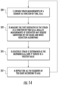
- the circuit with the at least one processor can also: obtain strain measurements of defined segments of myocardial heart tissue as a function of time as the measured strain; calculate a first derivative of the strain measurements as a function of time; and determine diastolic strain as a maximum positive value of the calculated first derivatives.
- the measured strain can include a first set of strain measurements and the generated longitudinal and circumferential heart models can be a first set of the longitudinal and circumferential heart models.
- the circuit with the at least one processor can also: obtain a second plurality of series of MRI images of long and short axis planes of a heart of a patient after a physical or chemically induced stress challenge, with each series of the MRI images is taken over a different single heartbeat of the heart of the patient during an image session that is five minutes or less of active scan time and with the patient in a bore of the MRI Scanner; and obtain a second set of regional and global strain measurements of the myocardial heart tissue of the heart of the patient based on the second plurality of series of MRI images of the heart of the patient; and generate at least one of: a post-challenge set of the longitudinal and circumferential heart models with the plurality of adjacent compartments, wherein the compartments are color-coded based on the strain measurements from the second series of MRI image slices; or a
- the circuit with the at least one processor can generate both of the post-challenge sets of the longitudinal and circumferential heart models and cause the at least one display to concurrently display both of the post-challenge sets with the first set of heart models.
- the challenge can be a low stress challenge requiring only an increase in heart rate of 10 beats per minute, and the circuit with the at least one processor can compare the first and second sets of strain measurements based on a low stress challenge the post-challenge
- the circuit with the at least one processor can evaluate dyssynchrony in heart contraction between chambers of the heart and/or in a single heart chamber of the heart of the patient based on a spatial non-uniformity of strain over a cardiac cycle.
- the circuit with the at least one processor can identify dyssynchrony based on a number between 0 to 1, where "0" represents full dyssynchrony and " 1" represents full synchrony, calculated for segments and/or chambers of the heart based on a dispersion of peak shortening over time of the cardiac cycle from the strain measurements obtained at different locations of the heart and different points of time of the cardiac cycle.
- the circuit can calculate a global strain measurement and compare it to predefined global values shown to designate normal and abnormal tissue to thereby delineate abnormal tissue as reversible or irreversible.
- inventions are directed to methods of rapidly evaluating cardiac function.
- the methods include: placing a patient in a bore of an MRI Scanner; electronically obtaining planning views of strain encoded (SENC) MRI images from transverse, sagittal and coronal planes to generate a pseudo two chamber view of the heart to determine orientation of the heart of the patient in a bore of the MR Scanner; identifying a pseudo two-chamber or a pseudo four-chamber imaging plane from the obtained planning views of the SENC images; electronically obtaining a series of MRI images from the pseudo two-chamber imaging plane or the pseudo four-chamber imaging plane over a single heart beat; identifying an MRI image with a maximum total intensity signal as being an MRI image slice associated with end systole (maximum contraction of the heart) from high tuning raw MRI images from the series of MRI images from the pseudo two-chamber or the pseudo four chamber imaging plane over the single heart beat; identifying three short axis imaging planes based on
- the planning views and the obtained first series of MRI imaging views can be free breathing MRI images thereby not requiring breath hold signal acquisition or cardiac gating, and wherein the first series of MRI images are obtained with a patient in the bore of the magnet between 1-3 minutes.
- the method can also include: presenting a stress-challenge to the patient; obtaining a second series of MRI images for each of the three short axis and the three long axis imaging planes, wherein each of the second series of the MRI images for the three short axis and the three long axis imaging planes are taken over a cardiac cycle of a different single heartbeat of the heart of the patient during an image session that is under five minutes of active scan time and with the patient in the bore of the MRI Scanner; generating a second set of regional and global strain measurements of myocardial heart tissue of the heart of the patient based on the obtained second series of MRI images for each of the three short axis and the three long axis imaging planes of the heart of the patient; and generating, within 15 minutes of a patient exiting the bore of the magnet, longitudinal and circumferential heart models with a plurality of adjacent compartments, wherein the compartments are color-coded based on the second set of strain measurements.
- the method can also include generating a post-challenge set of the longitudinal and circumferential heart models with the plurality of adjacent compartments, and the compartments can be color-coded based on a difference between the first and second sets of strain measurements.
- the method can include concurrently displaying the heart models with the first and second set of strain measurements and a post-challenge set of heart models based on a change in strain values of the different compartments of the heart models.
- the stress challenge can be a low stress challenge requiring only an increase in heart rate of 10 beats per minute.
- the method can include electronically valuating dyssynchrony in heart contraction between chambers of the heart and/or in a single heart chamber of the heart of the patient based on a spatial non-uniformity of strain over a cardiac cycle.
- the method can include electronically calculating dyssynchrony for all segments of the heart models over a time cycle of the cardiac cycle based on a dispersion of peak shortening over time of the cardiac cycle from the first set of strain measurements obtained at different locations of the heart and different points of time of the cardiac cycle.
- inventions are directed to methods of monitoring a heart of a patient during an MRI scanning session.
- the methods include: electronically obtaining a series of MRI images of target anatomy of a patient during an MRI scan session over a single heart beat; electronically obtaining a series of strain encoded (SENC) MRI images of a heart of the patient during the MRI scan session; electronically automatically monitoring status of the heart of the patient during the scan session to detect a potential adverse heart event during the scan session based on the obtained SENC MRI images; and electronically automatically generating an alert if a potential adverse heart event is detected.
- SENC strain encoded
- inventions are directed to methods of identifying cardiac dysfunction or injury.
- the methods include: (electronically) comparing strain measurements of different chambers of the heart or different regions of the heart to identify dyssynchrony based on a spatial non-uniformity of strain over a cardiac cycle.
- inventions are directed to method s of evaluating cardiac status by electronically determining diastolic strain measurements of the heart of the patient using strain encoded (SENC) MRI images of MRI image slices from long and short axis planes to evaluate at least one of cardiac function, impairment, disease or injury.
- SENC strain encoded
- a workstation that includes: at least one display; and a circuit at least partially onboard or in communication with an MRI Scanner and in communication with the at least one display.
- the circuit includes at least one processor that: obtains a plurality of series of MRI images of long and short axis planes of a heart of a patient, wherein each series of the MRI images is taken over a different single heartbeat of the heart of the patient during an image session that is under five minutes of active scan time and with the patient in a bore of the MRI Scanner; and obtains systolic and diastolic strain measurements of the heart of the patient using the series of MRI images from the long and short axis planes.
- the systolic strain measurements are negative and the diastolic strain measurements are positive, optionally the diastolic strain measurements include calculating a first derivative of strain as a function of time.
- the circuit with the at least one processor can obtain strain measurements of defined segments of myocardial heart tissue as a function of time; calculate a first derivative of the strain measurements as a function of time; and determine diastolic strain as a maximum positive value of the calculated first derivatives.
- inventions are directed to methods of planning scan planes of a heart of a patient.
- the methods include: electronically obtaining strain encoded MRI images from transverse, sagittal and coronal planes to generate a pseudo two chamber view of the heart to determine orientation of the heart of the patient in a bore of the MR Scanner; electronically identifying a pseudo two-chamber plane or a pseudo four-chamber plane from the obtained MRI images; electronically obtaining a series of MRI images from the pseudo two-chamber plane or the pseudo four-chamber plane over a single heart beat; electronically reviewing the obtained series of MRI images to identify an MRI image with a time with a maximum total intensity signal representing an end systole segment of the cardiac cycle; projecting three lines dividing the left ventricle of the identified MRI image to identify three short axis imaging planes; and projecting dividing lines through the identified MRI image to identify three long axis imaging planes.
- the series of MRI images can e from the pseudo two-chamber plane and/or a pseudo two-chamber strain encoded movie generated from the series of MRI images from the pseudo two-chamber plane used to identify the MRI image slice with the maximum total intensity signal are high tuning raw strain encoded movies.
- the series of MRI images can be from the pseudo four-chamber plane and/or a pseudo four-chamber strain encoded movie generated from the series of MRI images from the pseudo four-chamber plane used to identify the MRI image slice with the maximum total intensity signal are high tuning raw strain encoded movies.
- Still other embodiments are directed to methods for rapid MRI imaging of the heart.
- the methods include: electronically providing a SENC pulse sequence from a single view of a cut of the heart to acquire a strain movie, and then acquiring a multiplicity of movies from a multiplicity of views of cuts of the heart. Each movie is acquired in a single heartbeat.
- Yet other embodiments are directed to methods for quantifying muscle contractility from MRI images that include: electronically transmitting a multiplicity of SENC pulse sequences; electronically acquiring strain movies from the SENC pulse sequences of multiple views of the heart; electronically calculating strain measurement values at individual segments of heart muscle from the strain movies; and color coding the strain values in at least one model of the heart based on a degree of contractility associated with the calculated strain measurement values.
- Additional embodiments are directed to methods for quantifying stress on muscle contractility of a heart of a patient from MRI images.
- the methods include: transmitting a multiplicity of SENC pulse sequences from multiple views of the heart; acquiring strain movies from the SENC pulse sequences of the multiple views of the heart; electronically automatically calculating strain values at individual segments of heart muscle from the strain movies; and color coding a reduction in contractility in compartments of at least one heart model upon application of a stress to the patient to indicate reduced blood perfusion associated with coronary artery disease.
- Yet other embodiments are directed to MRI systems that include a processor that uses SENC images (raw and/or colored) for automatically planning of an imaging view to thereby provide a suitable imaging view without requiring human identification of a suitable imaging view based on multiple long and short axis planning views for the imaging view.
- SENC images raw and/or colored
- Still other embodiments are directed to MRI systems with at least one processor that automatically carries out a segmentation of heart ventricles of a patient from SENC images (raw and/or colored) and measures dimensions of the heart ventricles of the patient from the SENC images.
- SENC images raw and/or colored
- Yet other embodiments are directed to imaging processing systems for MRI systems with a circuit that generates a series of SENC raw heart images that are combined together to obtain an anatomical sequence and a strain sequence of heart muscle, with the strain sequence of heart images having color-coded perimeters or segments corresponding to calculations of strain values.
- the strain values include at least one of strain rate, mean strain or average strain.
- first, second, etc. may be used herein to describe various elements, components, regions, layers and/or sections, these elements, components, regions, layers and/or sections should not be limited by these terms. These terms are only used to distinguish one element, component, region, layer or section from another region, layer or section. Thus, a first element, component, region, layer or section discussed below could be termed a second element, component, region, layer or section without departing from the teachings of the present invention.
- spatially relative terms such as “beneath”, “below”, “lower”, “above”, “upper” and the like, may be used herein for ease of description to describe one element or feature's relationship to another element(s) or feature(s) as illustrated in the figures. It will be understood that the spatially relative terms are intended to encompass different orientations of the device in use or operation in addition to the orientation depicted in the figures. For example, if the device in the figures is turned over, elements described as “below” or “beneath” other elements or features would then be oriented “above” the other elements or features. Thus, the exemplary term “below” can encompass both an orientation of above and below.
- Embodiments of the invention are intended to improve the ability of MRI imaging to more quickly quantify and/or provide standardized reports that identify heart abnormalities and trends for physicians to direct patient management and/or treatment.
- circuit refers to an entirely software embodiment or an embodiment combining software and hardware aspects, features and/or components (including, for example, a processor and software associated therewith embedded therein and/or executable by, for programmatically directing and/or performing certain described actions, operations or method steps).
- program means that the operation or step can be directed and/or carried out by a digital signal processor and/or computer program code.
- electrotronically means that the step or operation can be carried out in an automated manner using electronic components rather than manually or using any mental steps.
- MRI scanner and MR scanner are used interchangeably to refer to a Magnetic Resonance Imaging system and includes the high-field magnet and the operating components, e.g., the RF amplifier, gradient amplifiers and processors that typically direct the pulse sequences and select the scan planes.
- Examples of current commercial scanners include: GE Healthcare: Signa 1.5T/3.0T; Philips Medical Systems: Achieva 1.5T/3.0T; Integra 1.5T; Siemens: MAGNETOM Avanto; MAGNETOM Espree; MAGNETOM Symphony; MAGNETOM Trio; and MAGNETOM Verio. It is contemplated that both vertical and horizontal bore MRI scanner systems may be used.
- the MR scanner can include a main operating/control system that is housed in one or more cabinets that reside in an MR control room while the MRI magnet resides in the MR scan suite.
- the control room and scan room can be referred to as an MR suite and the two rooms can be separated by an RF shield wall.
- the term "high-magnetic field" refers to field strengths above 0.5 T, typically above 1.0T, and more typically between about 1.5T and 10T.
- Embodiments of the invention may be particularly suitable for 1.5T and 3.0T systems, or higher field systems such as future contemplated systems at 4.0T, 5.0T, 6.0T, 7T, 8T, 9T and the like.
- Embodiments of the invention may also be useful with lower field portable MRI scanner systems.
- the methods and systems can also be applied to animal MRI data acquired from animal MRI scanners but may be particularly suitable for human patients.
- patient refers to humans and animals. Embodiments of the invention may be particularly suitable for human patients.
- clinical data means physician, radiologist, cardiologist, physicist, technician, nurse, physician assistant, or other medical personnel desiring to review medical data of a patient.
- workstation refers to a display and/or computer associated with an MR scanner.
- the workstation and/or computer or circuit with at least one processor can communicate the MR scanner, can be partially or totally onboard the MR scanner and can be remote from the MR scanner, for access by a clinician.
- Examples that are not part of the present invention may take the form of an entirely software embodiment or an embodiment combining software and hardware, all generally referred to herein as a "circuit” or “module.”
- the examples may take the form of a computer program product on a computer-usable storage medium having computer-usable program code embodied in the medium. Any suitable computer readable medium may be utilized including hard disks, CD-ROMs, optical storage devices, a transmission media such as those supporting the Internet or an intranet, or magnetic storage devices.
- Some circuits, modules or routines may be written in assembly language or even micro-code to enhance performance and/or memory usage.
- the functionality of any or all of the program modules may also be implemented using discrete hardware components, one or more application specific integrated circuits (ASICs), or a programmed digital signal processor or microcontroller. Examples are not limited to a particular programming language.
- Computer program code for carrying out operations of the present invention may be written in an object oriented programming language such as Java ® , Smalltalk or C++.
- the computer program code for carrying out operations of the present invention may also be written in conventional procedural programming languages, such as the "C" programming language.
- the program code may execute entirely on the user's computer, partly on the user's computer, as a stand-alone software package, partly on the user's computer and partly on another computer, local and/or remote or entirely on the other local or remote computer.
- the other local or remote computer may be connected to the user's computer through a local area network (LAN) or a wide area network (WAN), or the connection may be made to an external computer (for example, through the Internet using an Internet Service Provider).
- LAN local area network
- WAN wide area network
- Internet Service Provider for example, AT&T, MCI, Sprint, EarthLink, MSN, GTE, etc.
- Embodiments of the invention may be carried out using a cloud computing service (or an aggregation of multiple cloud resources), generally referred to as the "Cloud”.
- Cloud storage may include a model of networked computer data storage where data is stored on multiple virtual servers, rather than being hosted on one or more dedicated servers. Firewalls and suitable security protocols can be followed to exchange and/or analyze patient data.
- Strain imaging techniques that have improved upon traditional MRI techniques include Strain Encoded imaging (SENC), which is an MRI technique for imaging regional deformation of tissue, such as the heart muscle.
- SENC Strain Encoded imaging
- Prior, related art developments in MRI are not capable of providing high quality imagery of tissue that includes a quantitative measure of tissue deformation.
- SENC is able to measure movement of the heart muscle itself without relying on calculation of changes between the epicardium and endocardium to estimate regional wall motion. Directly measuring myocardial wall motion with SENC eliminates errors derived from manual estimation that hinder prior MRI or Non-MRI techniques of evaluating heart functionality.
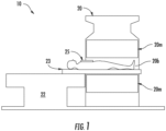
- the MRI system 10 uses an MRI scanner 20 with a high-magnetic field magnet 20m (1.5T, 3T or even greater or lower magnetic field strength), where the patient can be positioned on top of a translatable MRI table top 23 held by a table 22.
- the table top 23 can move and slide into and out of the MRI magnet bore 20b. This motion can be controlled from inside the MRI magnet room or from the console outside the magnet room (in the control room of an MRI suite, for example).
- Specialized or conventional chest coils 25 for imaging the thorax or the heart can be used.
- the patient can be in any position for imaging, a representative position for heart patients is to lie on their backs and enter the MRI feet first. It is also noted that vertical bore systems may also be used.
- FIGS. 2A-2C are schematic illustrations of different configurations of the MRI imaging system 10 according to embodiments of the present invention.
- the MRI imaging system incorporates an MR Scanner 20 with a high-magnetic field magnet 20m having a bore 20b , and includes the SENC pulse sequence and a workstation 60.
- the workstation 60 communicates with a cardiac module 10M and the module 10M can contain the software to generate the SENC pulse sequence and create strain sequences and compile the outcomes into standardized reports and/or heart models of global and regional values of circumferential and longitudinal strain that correlate to myocardial contraction and function.
- the workstation 60 can include a display 60d.
- the system 10 can include a circuit 10c with at least one processor for imaging processing the obtained MRI images and/or can comprise one or both of an SENC pulse sequence and/or the strain sequences and calculations that is onboard or remote from the workstation and comprises the module 10M.
- the system 10 can include a T/R switch 35 that can communicate with a chest coil 25.
- FIG. 2A illustrates that the system 10 can include at least one workstation 60 that has a portal for accessing the circuit 10c and/or cardiac module 10M.
- the circuit 10c may include at least one processor configured to provide the SENC pulse sequences, analyze the raw SENC images and/or calculate the strain measurements.
- the module 10M can be held on a remote server accessible via a LAN, WAN or Internet.
- the workstation 60 can communicate with the MR Scanner 20 and chest coil 25.
- the MR Scanner 20 typically directs the operation of the pulse sequence and image acquisition using the chest coil 25 and at least on transmit/receive switch 35 as is well known to those of skill in the art.
- the chest coil 25 can be any suitable thoracic or chest coil.
- the workstation 60 can include a display 60d with a GUI (graphic user input) and the access portal 60p.
- the workstation 60 can access the module 10M via a relatively broadband high speed connection using, for example, a LAN or may be remote and/or may have lesser bandwidth and/or speed, and for example, may access the data sets via a WAN and/or the Internet. Firewalls may be provided as appropriate for security.
- FIG. 2B illustrates that the module 10M can be partially or totally included in the MR Scanner 20 (i.e., a control console or computer) which can communicate with a workstation 60.
- the module 10M can be integrated into the control cabinet of the MR Scanner with image processing circuitry.
- the workstation 60 can be in the magnet room and/or the control room of an MRI suite or may be remote from the MRI suite.
- FIG. 2C illustrates that the module 10M can be integrated into one or more local or remote workstations 60 that communicates with the MR Scanner 20. Although not shown, parts of the module 10M can be held on both the Scanner 20 and one or more workstations 60 , which can be remote or local.
- the cardiac module 10M can be held on at least one server that can communicate with one or more Scanners 20.
- the at least one server can be provided using cloud computing which includes the provision of computational resources on demand via a computer network.
- the resources can be embodied as various infrastructure services (e.g., compute, storage, etc.) as well as applications, databases, file services, email, etc.
- infrastructure services e.g., compute, storage, etc.
- applications e.g., databases, file services, email, etc.
- cloud computing the user's computer may contain little software or data (perhaps an operating system and/or web browser), and may serve as little more than a display terminal for processes occurring on a network of external computers.
- Firewalls and suitable security protocols can be followed to exchange and/or analyze patient data.
- Strain Encoded Imaging is an MRI technique for imaging regional deformation of tissue, such as the heart muscle.
- the embodiments of the invention use a SENC pulse sequence to acquire a movie (a series of successive MRI images) of strain during a single heartbeat in a single view of a respective cut/slice of the heart using MRI.
- Multiple strain sequences are then acquired from predefined cuts (the word "cuts” is also referred to interchangeably herein as “slices” or “planes”) of the heart to quantify global and regional values of circumferential and longitudinal strain that correlate to myocardial contraction and function.
- the following mathematical equations/formulas can be used to set the parameters of the SENC pulse sequence to measure the contraction of the heart muscle:
- Raw SENC images are the images produced by the SENC pulse sequence. The raw images are used to estimate the strain from changes in intensity because of contraction. To do so, two different kinds of raw SENC images can be produced: one to capture the contraction of muscle, called “high tuning”, and the other to capture the no contraction or even stretching of the muscle, and this is called the “low tuning” images.
- s_min -0.30.
- the negative sign indicates contraction (shortening) of the muscle.
- the maximum range of the strain is: s_max ⁇ 1 + 2 ⁇ s _ min i . e . s _ max ⁇ 0.40 which means that the maximum strain that can be measured is 40% stretching. Assuming the slice thickness is 10 mm.
- the imaging sequence will measure strain accurately between +40% and -30%.
- the slice thickness can be the same or different between different slices, but is preferably the same.
- the slice thickness can be any appropriate thickness and is typically between 1 mm and 10 mm, more typically between 5-10 mm.
- the methods, systems and circuits of the invention employ a rapid strain encoding (SENC) pulse sequence to acquire, in a single heartbeat, a sequence of images of heart muscle functionality during the cardiac cycle and within a slice (plane) of the heart.
- This series of SENC raw images are combined together to obtain an anatomical sequence and a strain sequence of the heart muscle in that slice.
- the anatomical sequence shows the tissue of the heart as bright in contrast to lung tissue and blood that show much darker. This contrast allows for fast segmentation of (i.e. isolating in images) the heart muscle to separate from other tissues of the body.
- the strain sequence shows measurements of the contraction and relaxation of the heart muscle during the cardiac cycle; providing measurements of the contractility of the heart muscle.
- the anatomical and strain sequences also allow quick and repeatable calculations of global measures such as ejection fraction.
- SENC imaging techniques that enable fast segmentation of the heart chambers also enable rapid and automated calculation of traditional measures (e.g. ejection fraction of heart chambers, chamber volume, stroke volume, chamber mass, etc.).
- traditional measures e.g. ejection fraction of heart chambers, chamber volume, stroke volume, chamber mass, etc.
- the ability to quickly evaluate traditional measures with higher resolution images, characteristic of MRI, provides standardized metrics that can augment strain mapping to provide the clinician with critical information from which to diagnose and treat patients at risk of developing new or worsening heart failure.
- Embodiments of the invention can be carried out with minimal patient time inside the bore of the MRI magnet.
- the scan sequence can be carried out during free-breathing and for as short as 5 minutes, more typically between 2 minutes and 15 seconds or less in order to generate the data to produce all the quantitative measurements.
- the entire scan sequence can be acquired with as few as 4-6 strain sequences from 4-6 different imaging planes providing complete assessment of global function and segmental contractility within 4-6 heartbeats.
- the fast scan thereby produces a multiplicity of movies from a multiplicity of views or cuts of the heart where each movie is acquired in as fast as a single heartbeat.
- the term "movie” refers to a time sequence of a series of MRI images taken over a cardiac cycle and may be "raw” or unenhanced or may be color-coded with strain measurements, for example.
- the imaging planes can include at least 3 short axis planes covering the base, mid and apex of the ventricles.
- the imaging planes can also include at least one long axis plane (4-chamber view showing all the compartments of the heart) for a minimum of 4 planes.
- a representative case defines 3 long-axis views, adding 2-chamber and 3-chamber views to the 4-chamber view for a total of 6 planes.
- the imaging planes can be identified in a very fast way if the fast strain encoded imaging is used with its single heartbeat acquisition for each sequence of images on a single plane.
- a scan duration is the time the patient spends inside the magnet to acquire all the defined planes (i.e., at least 4 planes: 3 short-axis and one long-axis). This can take as short as 4 heartbeats.
- the imaging planes can have 6 planes, and the scan can take 6 heartbeats.
- the acquisition can be initiated by an operator, typically by pressing a "scan start button" to launch the strain encoding acquisition. Verbal or other launch initiation actions can be used.
- the scanning time can include an additional time period, such as about 20 seconds, for moving the patient into and out of the MRI magnet, making the whole scan time period, including patient movement into the bore of the magnet, between 60 seconds to about 30 seconds.
- FIGS. 3A-3C An exemplary sequence for moving a patient is illustrated in FIGS. 3A-3C.
- FIG. 3A shows a patient moved into the magnet bore 20b during a first timer period T1.
- FIG. 3B shows image acquisition scan time T2 and
- FIG. 3C shows the patient is transported out of the magnet bore 20 during a third time period T3.
- T1+T2+T3 ⁇ 5 minutes typically between 25 seconds and 90 seconds, such as about 25 seconds, about 30 seconds, about 40 seconds, about 50 seconds, about 60 seconds, about 70 seconds, about 80 seconds and about 90 seconds.
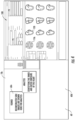
- FIG. 4 illustrates a display 60d with a viewer 60v that has a circuit 10c that can reconstruct SENC images for analysis and analyze inner and outer contours of the heart in different slices used to populate the strain measurements in the report 100.
- the figure shows the layout of the tool to show the reconstructed images, segmenting on that view, and filling the diagrams on the right side of the layout.
- FIGS. 5A-E show illustrations of an MRI scanner system with a workstation 60 having a display 60d that can display a patient report 100 with the cardiac models 110, 120.
- FIG. 5A shows a patient on the scanner table 22 outside the MRI scanner 20 prior to acquiring the patient strain data.
- FIG. 5B shows the patient positioned within the bore 20b of the magnet, ready for data acquisition.
- FIG. 5C shows the cardiac evaluation module 10M and/or circuit 10c directing the scanner 20 to scan the heart for a plurality of strain sequences along individual planes through the heart. Scanning the heart for the imaging plane views (i.e., 4- 6 views) of the heart (each producing a movie of the moving heart), can be carried out rapidly, typically takes less than 20 seconds, more typically 10 seconds or less.
- FIG. 5D illustrates the step of contouring one of the planes (window 60w 1 with the enlarged image(s) 102 ) to generate a strain sequence to evaluate circumferential strain, either manually or automatically, to define the heart chamber outline from which strain can be evaluated.
- Smaller cines or movies 105 of the 4-6 planes can be provided in an adjacent window 60w 2 .
- FIG. 5E illustrates contouring of a plane, either manually or automatically (enlarged view 102 ), to generate longitudinal strain within the defined chamber outline.
- a final strain report 100 showing all 6 strain sequences with final global and segmental strain values can be created in less than two minutes, typically 90 seconds or about 60 seconds (i.e., in about a minute) from when the last image signal acquisition from a patient is obtained so as to be generated in near-real time.
- segmental refers to the ability to calculate different strain measurements for different cardiac tissue types of across different regions of a cardiac wall, i.e., myocardial, endocardial and epicardial, for example.
- segmental strain measurements can provide differential strain measurements across a wall for different tissue types, i.e., myocardial and one or both of endocardial and epicardial tissue.
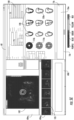
- the figure shows the layout of the representative report showing the measurements, both global and regional, and marking the abnormal strain values in a defined color, typically in a red font type.
- An appended color-coded graph 101g for the different tissue states can be provided on the report/display 100 to better delineate the actual strain values with level of myocardial contraction to differentiate normal from abnormal myocardial contraction as well as reversible from irreversible muscle weakening.
- Segmented 110s, 120s longitudinal and circumferential strain values can also be pictorially presented and color-coded to provide a relatively quick and easy evaluation of myocardial function.
- Traditional measures 130 can be calculated and presented on the report, including ejection fraction, left ventricular mass, left ventricular end-systolic volume, left ventricular end-diastolic volume, and left ventricular stroke volume. Other measurements can be calculated from SENC strain imaging and added to the report.
- the strain measurements of the color-coded graph 101g can be presented in colors (shown in FIG. 7 ) reflecting, in general, the 5 states of the heart muscle: hyperkinetic, normokinetic, hypokinetic, akinetic, and dyskinetic.
- the strain measurements can be presented as negative numbers, indicating shortening of the wall muscle at maximum contraction.
- strain measurement and “measured strain” refers to any quantifiable measure of strain including one or more of strain rate, average and mean, for example.
- the measured strain can be segmental and/or regional or both segmental and regional.
- the report can identify at least two important cutoffs:
- the Weak Cutoff and the Reversibility Cutoff 100 u 1 , 100u 2 can both be "universal" cutoff values that are clinically valid across gender and different age groups from pediatric to geriatric.
- Embodiments of the invention can employ a circuit 10c with at least one processor configured with a protocol/method to detect, segment and track myocardial muscle in four-chamber LA SENC and Fast SENC (e.g. FSENC) images using ASM, which depends on PCA, to encode shape variations found in the training data.
- FIG. 8 shows an example of a flowchart with actions for the detection, segmentation and tracking of the myocardial tissue.
- Training data 203 can be used to build the myocardium model and the myocardium mask 206.
- the circuit 10c can locate the myocardium 208 by analyzing the SENC images 102 and/or 105 , (intensity and/or strain) creating an "ACC" image 204 , and finally the circuit 10c can track the myocardium throughout the cardiac cycle 210 (i.e., using intensity).
- FIG. 8 also illustrates that the circuit 10c may comprise a machine learning system 201 that can be used to identify the myocardium with or without the ACC image 204 , models and masks 208 , for example.
- the machine learning system 201 can be configured to use the training data 203.
- Machine learning systems are well known to those of skill in the art. See, e.g., H. Irshad et al., Methods for nuclei detection, segmentation, and classification in histopathology: A review-current status and future potential, IEEE Rev. Biomed. Eng., vol. 7, pp. 97-114 (2014 ).
- FIGS. 12 , 14 and 15 may also incorporate or use machining learning systems (i.e., artificial intelligence systems) according to embodiments of the present invention.
- machining learning systems i.e., artificial intelligence systems
- FIGS. 9A -H Various exemplary steps for constructing an ACC image are shown in the A-H images/image frames of FIGS. 9A -H: 9 (A) four frames of typical SENC images, 9 (B) Images after applying opening by reconstruction, 9 (C) Images after threshold, 9 (D) ACC image, 9 (E) strain information is used to detect chest wall, 9 (F) Final ACC image, 9 (G) mean shape X overlaid on the myocardium location after determining the maximum convolution value between Mask and ACC, 9 (H) the mean shape X deforms to this specific patient myocardial shape.
- 9 (A) four frames of typical SENC images 9 (B) Images after applying opening by reconstruction, 9 (C) Images after threshold, 9 (D) ACC image, 9 (E) strain information is used to detect chest wall, 9 (F) Final ACC image, 9 (G) mean shape X overlaid on the myocardium location after determining the maximum convolution value between Mask and ACC, 9 (H)
- FIGS. 10A-C show SENC raw images 102r with a plurality of (shown as three) different cuts or planes 102c for fast automated planning of imaging views.
- SENC raw images 102r can be used to determine these imaging planes.
- the advantage is the fast acquisition of the SENC raw images (a single heartbeat per sequence) that does not require breath hold. Images close to the maximum contraction of the heart (end systole) can be used to plan to the correct imaging views.
- FIG. 11A shows the steps taken by the operator of the MRI scanner to fast plan for imaging the heart using SENC strain images.
- the operator can save significant time and complexity by replacing the multiple conventional cine images of the heart, that each take at least one several seconds breath hold by SENC movies that take only a single heartbeat acquisition. Therefore, the prescription (planning) time is shortened significantly.
- imaging (view) planes will be defined: 3 short-axis at the base, mid and apex of the left ventricle, and 3 long-axis views of the 2-chamber, 3-chamber and 4 chamber planes. Multi-plane acquisition of transverse, sagittal and coronal planes is obtained (block 220 ).
- Pseudo 2-chamber plane can be automatically prescribed from the transverse images (block 222 ).
- Pseudo 2-chamber SENC movie can be generated (block 224 ).
- a pseudo 4-chamber plane can be automatically prescribed from the pseudo 2-chamber strain movie (block 226 ).
- a pseudo 4-chamber SENC strain movie can be generated (block 228 ).
- Three (3) short axis planes can be automatically prescribed from the pseudo 2-chamer strain movie (block 230 ).
- SAB short axis basal
- SAM short axis medial
- SAA short axis apical SENC strain movies
- Three (3) long axis planes can be automatically prescribed from the pseudo 2-chamber strain movie (block 234 ).
- Two chamber, three chamber and four chamber SENC strain movies can then be generated (block 236 ).
- FIG. 11B shows the produced images by following the steps described by FIG. 11A .
- the first set of images (step 1) are the standard images acquired in any cardiac MRI exam to help in locating the heart.
- the bottom colored images with the appended graphs of intensity versus time are the SENC strain images obtained in steps 2 (block 222 ), 4 (block 228 ) and 6 (block 232 ).
- the prescription planes P are defined by the white thick lines inside the images.
- the term "pseudo" in the case of cardiac MRI imaging means that the view of the heart is approximate to the actual view.
- the concept is that in order to reach a standard view of the heart (3 chamber, 4 chamber, 2 chamber) using MRI, some preliminary MRI images, which can be presented as movies of cuts of the heart, can be obtained to determine the orientation of the heart.
- the first "approximate" 2 chamber view of the heart may not be very accurate (that is why it is called pseudo 2 chamber in FIGS. 11A and 11B ), but it can be an important view to find a "true" 2 chamber view of respective patients in the bore of the magnet.
- the evaluation described with respect to FIGS. 11A and 11B can start with a pseudo 4 chamber plane and images, then obtain the pseudo 2 chamber plane and images.
- current cardiac MRI planning images to identify the position and orientation of the heart can be modified to use SENC strain images that replace the conventional cine (movie) images.
- the SENC fast pulse sequence can be used to automate the planning phase of imaging, which is the initial step in any cardiac MRI exam.
- Planning using SENC can have two steps: 1) locating the heart to delineate the position of the heart relative to other anatomy within the imaging field of view; and 2) determining the orientation of the ventricles to define the principal axes of the heart.
- the preparation for any cardiac acquisition can be automated using the single heartbeat SENC acquisition to avoid lengthy, manual planning of the planes prior to any SENC test or conventional cardiac MRI to shorten the time of imaging. Automated planning also will allow patient movement in between scans to avoid claustrophobia by shortening scanning segments, allow interventions such as contrast or other agent injections without worrying that movement of the patient may ruin the entire imaging if the patient doesn't return to the exact spot, or allow patient movement to mechanically increase contractility and/or heart rate to stress the heart and observe changes in heart movement to identify wall motion abnormalities.
- FIG. 12 shows exemplary steps for automatic planning (prescription) to find the same 6 planes similar to those obtained in FIGS. 11A and 11B without manual positioning or principal axes definition.
- the automatic planning leverages SENC imaging's ability to quickly and reliably identify the contracting heart by its brightness in the high tuning (HT) images.
- the steps mirror those of the manual approach but with the use of an object recognition algorithm to identify the heart.
- the only manual interaction that may, in some embodiments, be used, can be an identification of the best transverse view of the heart from the multi plane acquisition to start the automated planning steps.
- Multi-plane acquisition of transverse, sagittal and coronal planes is performed (block 270 ).
- a pseudo two-chamber plane can be automatically prescribed from the transverse images (block 272 ).
- a pseudo 2-chamber SENC HT movie is obtained (block 274 ).
- a time for maximum total signal is identified in a frame of the movie as associated with close to end-systole (block 276 ). This is shown by a highlighted perimeter of a medial frame.
- Automatically determining a line of the pseudo 4 chamber SENC HT dividing the LV (block 278 ).
- a time for maximum total signal is identified in a frame of the movie (associated with close to end-systole)(block 282 ).
- Automatically determining three lines of short axis SENC HT dividing the LV block 284 ).
- SAB, SAM and SAA SENC strain movies are obtained/generated (block 286 ).
- a time for maximum total signal is identified in frames of the movies (associated with close to end-systole)(block 288 ).
- Automatically determining three long axis planes from the pseudo 2chamber (or 4-chamber) strain movie (block 290 ). Generate the two chamber, three chamber and 4 chamber strain movies (block 292 ).
- Embodiments of the invention include stress exams that can be performed using multiple fast SENC strain imaging scans of the heart, at least one at rest and at least one in a different degree of stress to detect ischemia characteristic of coronary artery diseases.
- the stress test can also show improvement in myocardial function, characterized by a decrease in strain, under stress demonstrating viability in patients who have weakened myocardial contraction at rest.
- Fast scans utilizing SENC strain imaging can assess ischemia in patients with coronary artery disease by comparing the SENC strain sequences under stress vs at rest.
- the fast scan can acquire SENC strain sequences to measure segmental function of the heart at rest, then the measurements will be repeated for the heart under stress.
- the stress component of the test can utilize any form of exercise that can induce wall motion abnormality in case of ischemia, or pharmacological agents that will have the same effects (e.g. dobutamine and adenosine).
- SENC strain imaging with its higher sensitivity requires less stress to accurately identify ischemic myocardium thus shortening the acquisition time, exposing the patient to far lower levels of stress, and reducing the risks of eliciting a stress response. This enables identifying ischemia through administration of much smaller doses of pharmacological agents (e.g. dobutamine, adenosine, etc.), utilization of less risky agents that evoke a lower stress response, and/or incorporation of non-pharmacological mechanisms such as treadmill, Valsalva maneuvers, minimal exercise of the upper or lower body with the patient in supine position remaining on the table to expedite SENC imaging.
- pharmacological agents e.g. dobutamine, adenosine, etc.
- non-pharmacological mechanisms such as treadmill, Valsalva maneuvers, minimal exercise of the upper or lower body with the patient in supine position remaining on the table to expedite SENC imaging.
- ischemic exercises that produce a low level increase in stress from rest may be utilized to cause a mild increase in contractility from which the changes in SENC strain from rest to stress can determine an ischemic effect.
- patients may utilize a modified stair stepper or bicycle so the patient can remain lying on the table while exercising to raise their heart contractility.
- modified weights such as elongated balloons filled with sand or water or hand grips that provide tension when squeezed may be utilized as exercise to increase contractility.
- the increase in contractility may be partially correlated with an increase in heart rate to identify the timing from which the stress strain sequences should be acquired. For example, a heart rate increase of 10-20 beats per minute (bpm) is associated with a corresponding increase in contractility from which SENC stress testing can detect an ischemic response.
- bpm beats per minute
- the ability to tailor the type of stress testing medium to patients needs accommodates differences in patient tolerance to pharmacological agents, ability to walk or exercise while standing up, frailty in exertion due to underlying comorbidities, or other condition that allows the physician to choose a specific stress medium.
- the stress report 100 shown in FIGS. 13A & B , can show the strain measurements obtained with the fast scan at rest 100a (first row) and under stress 100b (second row) and the change in strain measurements 100c (third row) to show regions in heart models 110, 120 with potential ischemia, an indication of coronary artery stenosis.
- the color coding in these two representative examples show different representative ways to graphically delineate myocardial contraction based on strain measurement values.
- FIG. 13A shows a stress report 100 in which the absolute change in strain is determined by subtracting strain stress (the strain at stressed condition) minus strain rest (the strain at rest) and ranges from 0% to 10% to delineate ischemia.
- Changes in strain in the models 110, 120 in the change set of models 100c that identify viability (negative numbers with this calculation) can be lighter, such as shown as white in associated compartments 110w, 120w with the value set to 0%.
- Patient vitals 165 heart rate and blood pressure
- stress 165s can be provided adjacent the heart models for these conditions, 100a, 100b, respectively.
- FIG. 13B modifies the calculation to identify myocardial viability and distinguish it from ischemia.
- the absolute change in strain was calculated by subtracting strain rest minus strain stress and color coding positive changes (delineating myocardial viability due to a decrease in strain, improved contraction, from rest to stressed condition) in gradients of defined colors such as, for example, green and negative changes (delineating myocardial ischemia due to an increase in strain, worse contraction, from rest to stressed condition) in gradients of red with white demonstrating no change in strain from rest to stressed condition.
- red and blue rather than red and green or other color differentiation to reflect weakening or strengthening of strain, respectively.
- FIG. 14 shows exemplary steps to measure the diastolic strain rate from strain measurements obtained at different segments and different times of the cardiac cycle.
- the strain rate is obtained from the temporal derivatives of the strain curves and measuring the maximum positive strain rate that determines the rate of stretching of the myocardium during diastole. Methods for reducing noise and curve fitting can be used to reduce the noise effect on measuring the derivatives.
- Strain measurements are obtained of a segment as a function of time, E(tn)(block 300 ).
- the first derivative of strain is measured as a function of time Er(tn)dE(tn)/dt (block 302 ).
- Measurements of derivative can include smoothing of the values and noise reduction algorithms.
- Blocks 300-305 can be repeated for all segments of the heart according to AHA (American Heart Association) standardized models (block 307 ).
- the rapid relaxation of the heart muscle during the ventricles' filling can be measured from the rate of change of the measured strain at different segments of the heart muscle during the filling. These relaxation strain rate will reflect the stiffness of the ventricles associated with some cardiac diseases. Measuring strain rate during diastole directly measures spatial deformation of the muscle which can be correlated to relaxation. Identifying patients with a minimum diastolic strain rate ⁇ -31 sec -1 identifies patients with myocardial dysfunction who are at risk of diastolic heart failure [ Neizel M, et al.
- Embodiments of the invention also measure temporal differences in strain and/or strain rate between various chambers of the heart or throughout a single heart chamber to identify dyssynchrony and predict the impact of various management algorithms on improvement in myocardial function. Evaluating the time difference between peak strain, which is associated with tissue deformation during systole, or calculating circumferential uniformity ratio estimate [CURE] index values for patients with left bundle branch block and/or patients with transmural infarcts can be used to determine heart failure that may benefit from resynchronization therapy and/or other intervention that address the delay in myocardial contraction.
- CURE circumferential uniformity ratio estimate
- FIG. 15 shows three exemplary approaches to measure dyssynchrony from strain measurements obtained at different locations and different points of time. Measuring strain throughout the cardiac cycle and optimizing predicted ejection fraction improvement by altering the timing of contraction of various chambers and/or throughout the chambers themselves can estimate the likelihood of treatment success utilizing various modalities to identify responders and/or guide the strategy of placement of leads or other stimulation modality to optimize synchrony and contraction of the heart.
- Strain measurements are measured from SENC images for all segments and times E(s,t n ) (block 400 ).
- Dyssynchrony can be measured as the dispersion of peak shortening.
- Dys1 var(Ts, such that Ts is the time of minimum strain of any segment(s) (block 402 ).
- Dyssynchrony can be measured as the spatial non-uniformity of strain.
- Dys 2 A / A + B
- the distinctive element of SENC testing involves the unique ability to quantify myocardial deformation by directly measuring strain using magnetic resonance imaging. This measurement identifies the level of myocardial contraction and provides an indication of weakening of heart muscle which precedes heart failure.
- FIG. 16 shows a decision tree to utilize SENC testing for diagnosing and managing patients with risk factors of systolic heart failure. Patients who are susceptible to myocardial dysfunction that puts them on the progressive path towards heart failure can be evaluated with SENC testing.
- Patients with symptoms or indicators of coronary artery disease can be tested with SENC strain imaging at rest and under stress from pharmacological agents or completely non-invasive methods such as exercise, maneuvers such as Valsalva, or other techniques that increase contractility.
- the difference in strain measurements at rest and under stress identifies myocardial ischemia and/or myocardial viability.
- the extent of myocardial ischemia correlates to coronary stenosis and indicates the need for further evaluation and potential revascularization through percutaneous coronary intervention or bypass grafting.
- Improved strain in weakened myocardium under stress e.g. decrease in strain from rest to stressed condition
- myocardial viability since it characterizes improved myocardial contraction under stress despite showing weakened myocardial contraction at rest.
- SENC stress testing also generates a strain map that delineates myocardial dysfunction identifying weakened myocardium that may result from a prior infarction or other comorbidity that reduces contractility of the myocardium.
- the stress and strain maps guide management or targeted treatment of the patient based on the extent and location of ischemia and myocardial dysfunction. After revascularization or medical management, in cases where intervention is not warranted, the impact of treatment on myocardial function is evaluated by repeat strain mapping to determine heart remodeling and improvement in myocardial contractility.
- myocardial subclinical dysfunction Patients without symptoms or indicators of coronary artery disease or those in which ischemia is ruled out are evaluated for myocardial subclinical dysfunction with strain mapping. The extent of myocardial dysfunction is used to direct management and tailored treatment.
- FIG. 17 shows a decision tree to tailor patient management based on quantified SENC strain values and strain mapping to prevent, delay, and/or interrupt heart failure progression.
- Patients with strain between -10% and -17% are characterized by weakened myocardium that is reversible but, left unchecked, will likely progress to heart failure.
- Patients with reversible myocardial weakening are managed medically or with targeted treatment to improve contractility and address risk factors or underlying conditions that led to reduced myocardial function.
- a patient with a normal ejection fraction above 50%, normal diastolic function but global strain of -12% (ranging between -10% and -17%) and a history of mitral valve disease with moderate or severe regurgitation may be referred for evaluation of mitral valve repair or replacement to address the underlying condition causing progressive dysfunction before heart failure develops and the damage is permanent.
- Repeat or periodic strain tests can evaluate the impact of medical management or targeted treatment on reversible myocardial dysfunction.
- Prescribed drugs and/or doses can be titrated to optimize improvement in myocardial function under guidance from sequential strain maps. If strain values decrease or remain the same in the abnormal range, changes in prescribed drugs, dosage, or combination drug therapy may be utilized to encourage reverse remodeling and improvement in the underlying condition that caused weakened myocardium or contractility itself.
- targeted treatment e.g. catheter or surgical intervention
- myocardial function may be quantified with strain maps to determine the relationship between the underlying disease and myocardial weakening or the quality of intervention, and determine subsequent medical management or targeted treatment.
- Strain mapping may also be utilized in the perioperative period (e.g. ⁇ 30 days) after targeted treatment to predict adverse events related to any procedure.
- pericardial and pleural effusions may cause cardiac dysfunction by increasing the pressure around the heart.
- Quantification of myocardial dysfunction may provide an early indicator of progressive effects before tamponade occurs, enabling early medical management that avoids the need for emergent draining or adverse sequelae that may result.
- Patients with global strain > -10% may have heart failure that will progress to a point where myocardial dysfunction is irreversible. These patients can be managed medically or with targeted treatment to delay or interrupt worsening heart failure and guide initiation of more aggressive interventions before systemic effects ensue and/or complications occur.
- Patients with worsening heart failure, preceded by progressively and continued weakening myocardial dysfunction, may be candidates of aggressive intervention such as ventricular assist device therapy or heart transplantation.
- Strain mapping may be used to guide initiation of such treatment modalities before systemic injury results from severely weakened myocardium. Providing a strain metric to justify aggressive intervention standardizes treatment based on quantifiable diagnostic information and minimizes subjective evaluation of the extent of myocardial damage or poor indicators such as ejection fraction obtained by subjective delineation of wall motion.
- SENC imaging has the ability to measure both systolic dysfunction (i.e. weakening contraction) and diastolic dysfunction (i.e. stiffening myocardium with reduced relaxation).
- FIG. 18 shows a block diagram describing the use of SENC imaging to measure both strain and strain rate in patients to quantify the extent and risk of heart failure independent of the source of reduced myocardial health. This includes patients at risk of heart failure with reduced ejection fraction indicative of systolic heart failure, and heart failure with preserved ejection fraction indicative of diastolic heart failure.
- strain which quantifies myocardial contraction and strain rate which quantifies myocardial relaxation enables delineation of the type of heart failure and guide risk reduction, medical management and/or targeted treatment regimens.
- strain and strain rate By measuring both strain and strain rate and comparing to global values shown to designate normal and abnormal tissue, and further delineate abnormal tissue as reversible or irreversible, the appropriate management strategy can be employed before changes in ejection fraction are identified, at which point either type of heart failure has a poor prognosis.
Landscapes
- Health & Medical Sciences (AREA)
- Life Sciences & Earth Sciences (AREA)
- Engineering & Computer Science (AREA)
- Public Health (AREA)
- Medical Informatics (AREA)
- General Health & Medical Sciences (AREA)
- Biomedical Technology (AREA)
- Physics & Mathematics (AREA)
- Pathology (AREA)
- Nuclear Medicine, Radiotherapy & Molecular Imaging (AREA)
- Heart & Thoracic Surgery (AREA)
- Molecular Biology (AREA)
- Surgery (AREA)
- Animal Behavior & Ethology (AREA)
- Biophysics (AREA)
- Veterinary Medicine (AREA)
- Radiology & Medical Imaging (AREA)
- Signal Processing (AREA)
- Physiology (AREA)
- Primary Health Care (AREA)
- Epidemiology (AREA)
- Computer Vision & Pattern Recognition (AREA)
- Artificial Intelligence (AREA)
- Psychiatry (AREA)
- Cardiology (AREA)
- High Energy & Nuclear Physics (AREA)
- Data Mining & Analysis (AREA)
- Databases & Information Systems (AREA)
- General Business, Economics & Management (AREA)
- Business, Economics & Management (AREA)
- Dentistry (AREA)
- Oral & Maxillofacial Surgery (AREA)
- Magnetic Resonance Imaging Apparatus (AREA)
Claims (11)
- Poste de travail médical (60), comprenant:au moins un affichage (60d); etun circuit (10c) au moins partiellement embarqué ou en communication avec un scanner IRM (20) et en communication avec l'au moins un affichage (60d), le circuit comprenant au moins un processeur configuré pour:obtenir une pluralité de séries d'images IRM de plans à axes longs et courts d'un coeur d'un patient, dans lequel chaque série des images IRM est prise sur un battement unique différent du coeur du patient pendant une session d'images qui est de cinq minutes ou moins de temps de scannage actif et avec le patient dans un tube (20b) du scanner IRM (20);mesurer l'effort du tissu cardiaque myocardique du coeur du patient en se basant sur la pluralité de séries d'images IRM du coeur du patient; etgénérer des modèles cardiaques longitudinaux et circonférentiels avec une pluralité de compartiments adjacents, dans lequel les compartiments ont un code couleur basé sur l'effort mesuré,dans lequel le circuit avec l'au moins un processeur fait que l'au moins un affichage (60d) affiche en même temps la pluralité de modèles cardiaques générés avec l'effort mesuré, caractérisé en ce que les modèles cardiaques générés qui sont affichés en même temps comprennent un modèle cardiaque à trois chambres, un modèle cardiaque à quatre chambres et un modèle cardiaque à deux chambres avec l'effort mesuré pour l'effort circonférentiel, etdans lequel le modèle cardiaque à trois chambres, le modèle cardiaque à quatre chambres et le modèle cardiaque à deux chambres montrent au moins sept compartiments adjacents associés à un compartiment inféro-latéral basal, un compartiment inféro-latéral médian, un compartiment latéral apical, un compartiment antéro-septal basal, un compartiment antéro-septal médian, un compartiment antérieur apical et un bouchon apical, et dans lequel chaque compartiment peut avoir une valeur d'effort mesuré différente;le circuit avec l'au moins un processeur étant également configuré pour:obtenir une série d'images IRM du coeur venant des plans transverse, sagittal et coronal pour générer une pseudo-vue de deux chambres du coeur pour déterminer l'orientation du coeur du patient dans un tube (20b) du scanner IRM;identifier un pseudo-plan de deux chambres ou un pseudo-plan de quatre chambres venant des images IRM obtenues;obtenir une série d'images IRM à partir du pseudo-plan de deux chambres ou du pseudo-plan de quatre chambres sur un battement cardiaque unique;générer un film encodé de pseudo-effort de deux chambres venant de la série d'images IRM du pseudo-plan de deux chambres ou générer un film encodé de pseudo-effort de quatre chambres venant de la série d'images IRM du pseudo-plan de quatre chambres; puisidentifier un pseudo-plan de quatre chambres à partir du film encodé de pseudo-effort de deux chambres ou identifier un pseudo-plan de deux chambres à partir du film encodé de pseudo-effort de quatre chambres;identifier trois plans d'imagerie à axe court à partir du film encodé de pseudo-effort de deux chambres comme étant les plans à axe court pour la pluralité de série des images IRM pour les mesures d'effort calculées;générer un des films encodés d'effort basal à axe court (SAB), médian à axe court (SAM) et apical à axe court (SAA) venant de la série d'images IRM des trois plans à axe court identifiés; etidentifier trois plans d'imagerie à axes longs à partir du film encodé de pseudo-effort de deux chambres comme étant les plans longitudinaux pour la pluralité de série d'images IRM pour les mesures d'effort.
- Poste de travail (60) selon la revendication 1, dans lequel le circuit avec l'au moins un processeur dirige le scanner IRM (20) à acquérir la pluralité de séries d'images IRM en tant qu'images de respiration libre sans nécessiter de synchronisation cardiaque de six plans différents du coeur comme étant les plans à axe long et court, et dans lequel le circuit avec l'au moins un processeur génère des films respectifs de la série d'images IRM pour les différents plans à axe long et court et fait que l'au moins un affichage (60d) affiche les films des images IRM, et dans lequel le tissu cardiaque myocardique dans les films des images IRM montre des mesures d'effort en utilisant des couleurs qui varient sur la durée en se basant sur une quantité de déformation d'effort à travers le cycle cardiaque.
- Poste de travail (60) selon la revendication 1, dans lequel le circuit avec l'au moins un processeur génère en outre, et fait que l'au moins un affichage (60d) affiche en même temps, une barre de référence visuelle qui identifie une première valeur d'effort universelle qui correspond à un dysfonctionnement myocardique réversible et une seconde valeur d'effort universelle qui correspond à un dysfonctionnement myocardique irréversible.
- Poste de travail (60) selon la revendication 1, dans lequel les modèles cardiaques affichés en même temps comprennent un modèle de compartiment d'effort longitudinal avec des régions basales, médianes et apicales, dans lequel les régions basales et médianes comprennent chacune un compartiment antérieur, un compartiment antéro-septal, un compartiment inféroseptal, un compartiment inférieur, un compartiment inféro-latéral, et un compartiment antéro-latéral, et dans lequel la région apicale comprenant un compartiment antérieur, un compartiment septal, un compartiment inférieur et un compartiment latéral.
- Poste de travail (60) selon la revendication 1, dans lequel le circuit avec l'au moins un processeur dirige le scanner IRM (20) à générer une séquence d'impulsions pour obtenir la pluralité de la série d'images IRM du coeur du patient pour mesurer l'effort avec une fréquence d'encodage définie (w_0), un tuning bas (w_L) et un tuning élevé (w_H) comme suit:


- Poste de travail (60) selon la revendication 1, dans lequel le circuit avec l'au moins un processeur:recherche la série d'images IRM à partir du pseudo-plan de deux chambres et/ou du film encodé de pseudo-effort de deux chambres pour identifier une image IRM avec un temps avec un signal d'intensité total maximal pour identifier un segment de systole près de la fin du cycle cardiaque ;projeter une ligne divisant le ventricule gauche pour l'identification du pseudo-plan de 4 chambres; etprojeter trois lignes divisant le ventricule gauche pour l'identification du trois plans à axes courts.
- Poste de travail (60) selon la revendication 1, dans lequel le circuit avec l'au moins un processeur:crée un modèle de forme active (ASM) d'une région myocardique du coeur du patient, avec une forme et une pluralité de noeuds ou de points;crée un masque myocardique en combinant deux masques binaires incluant un masque myocardique et un masque de pool sanguin pour détecter l'emplacement du myocarde du coeur du patient;génère une image accumulée (ACC) qui représente le myocarde à la systole finale;corrèle l'image ACC avec le masque myocardique pour déterminer un emplacement du myocarde; etsuit le myocarde à travers le cycle cardiaque en utilisant l'ASM avec la corrélation en tant qu'une initialisation pour que l'ASM obtienne la série d'images IRM de différentes tranches à axe long et court.
- Poste de travail (60) selon la revendication 1, dans lequel le circuit avec l'au moins un processeur:obtient des mesures d'effort de segments définis de tissu cardiaque myocardique en fonction du temps en tant qu'effort mesuré;calcule une première dérivée des mesures d'effort en fonction du temps; etdétermine l'effort diastolique en tant qu'une valeur positive maximale des premières dérivées calculées.
- Poste de travail (60) selon la revendication 1, dans lequel l'effort mesuré comprend un premier jeu de mesures d'effort et les modèles cardiaques longitudinaux et circonférentiels générés sont un premier jeu des modèles cardiaques longitudinaux et circonférentiels, et dans lequel le circuit avec l'au moins un processeur:obtient une seconde pluralité de séries d'images IRM de plans à axe long et court d'un coeur d'un patient après un challenge d'effort physique ou induit chimiquement, dans lequel chaque série des images IRM est prise sur un battement unique différent du coeur du patient pendant une session d'images qui est de cinq minutes ou moins de temps de scannage actif avec le patient dans un tube (20b) du scanner IRM (20); etobtient un second jeu de mesures d'effort régionales et globales du tissu cardiaque myocardique du coeur du patient en se basant sur la seconde pluralité de séries d'images IRM du coeur du patient; etgénère au moins un de:un jeu post- challenge des modèles cardiaques longitudinaux et circonférentiels avec la pluralité de compartiments adjacents, dans lequel les compartiments ont un code couleur basé sur les mesures d'effort venant de la seconde série de tranches d'images IRM; ouun jeu post- challenge des modèles cardiaques longitudinaux et circonférentiels avec la pluralité de compartiments adjacents, dans lequel les compartiments ont un code couleur basé sur une différence entre les premier et second jeux de mesures d'effort.
- Poste de travail (60) selon la revendication 1, dans lequel le circuit avec l'au moins un processeur évalue la dyssynchronie dans la contraction cardiaque entre les chambres cardiaques et/ou dans une seule chambre cardiaque du coeur du patient en se basant sur une non-uniformité spatiale d'effort sur un cycle cardiaque.
- Poste de travail (60) selon la revendication 10, dans lequel le circuit avec l'au moins un processeur identifie la dyssynchronie en se basant sur un nombre entre 0 et 1, où « 0 » représente la dyssynchronie totale et « 1 » représente la synchronie totale, calculée pour des segments et/ou des chambres du coeur en se basant sur une dispersion de réduction maximale sur la durée du cycle cardiaque venant des mesures d'effort obtenues à différents emplacements du coeur et différents points dans le temps du cycle cardiaque.
Applications Claiming Priority (3)
| Application Number | Priority Date | Filing Date | Title |
|---|---|---|---|
| US201662328374P | 2016-04-27 | 2016-04-27 | |
| US201662415767P | 2016-11-01 | 2016-11-01 | |
| PCT/US2017/029602 WO2017189706A1 (fr) | 2016-04-27 | 2017-04-26 | Évaluations quantitatives rapides de la fonction cardiaque avec des mesures de contrainte provenant d'irm |
Publications (4)
| Publication Number | Publication Date |
|---|---|
| EP3448253A1 EP3448253A1 (fr) | 2019-03-06 |
| EP3448253A4 EP3448253A4 (fr) | 2020-04-08 |
| EP3448253B1 true EP3448253B1 (fr) | 2024-06-12 |
| EP3448253C0 EP3448253C0 (fr) | 2024-06-12 |
Family
ID=60157320
Family Applications (1)
| Application Number | Title | Priority Date | Filing Date |
|---|---|---|---|
| EP17790330.9A Active EP3448253B1 (fr) | 2016-04-27 | 2017-04-26 | Évaluations quantitatives rapides de la fonction cardiaque avec des mesures de contrainte provenant d'irm |
Country Status (6)
| Country | Link |
|---|---|
| US (4) | US10524687B2 (fr) |
| EP (1) | EP3448253B1 (fr) |
| JP (2) | JP7163278B2 (fr) |
| CN (1) | CN109310362B (fr) |
| CA (1) | CA3020896A1 (fr) |
| WO (1) | WO2017189706A1 (fr) |
Families Citing this family (22)
| Publication number | Priority date | Publication date | Assignee | Title |
|---|---|---|---|---|
| JP7163278B2 (ja) | 2016-04-27 | 2022-10-31 | マイオカーディアル ソリューションズ インク. | Mriのストレイン測定値による心機能の迅速な定量評価 |
| GB201610269D0 (en) | 2016-06-13 | 2016-07-27 | Isis Innovation | Image-based diagnostic systems |
| WO2019083934A1 (fr) * | 2017-10-24 | 2019-05-02 | The University Of Chicago | Imagerie combinée d'utilisation d'oxygène, de contrainte et anatomique avec une imagerie par résonance magnétique |
| JP6988001B2 (ja) * | 2018-08-30 | 2022-01-05 | オリンパス株式会社 | 記録装置、画像観察装置、観察システム、観察システムの制御方法、及び観察システムの作動プログラム |
| WO2020185868A1 (fr) * | 2019-03-13 | 2020-09-17 | University Of Virginia Patent Foundation | Système, procédé et milieu lisible par ordinateur pour la prédiction rapide d'une réponse cardiaque à un état du cœur et stratégie de traitement |
| US11103142B2 (en) * | 2019-04-02 | 2021-08-31 | Tencent America LLC | System and method for predicting vertebral artery dissection |
| US11872019B2 (en) | 2019-06-05 | 2024-01-16 | Myocardial Solutions, Inc. | MRI-derived strain-based measurements and related image data acquisitions, image data processing, patient evaluations and monitoring methods and systems |
| US12121712B2 (en) | 2019-11-25 | 2024-10-22 | Children's Hospital Los Angeles | Artificial right atrium design for failing Fontans |
| US11315246B2 (en) * | 2019-11-27 | 2022-04-26 | Shanghai United Imaging Intelligence Co., Ltd. | Cardiac feature tracking |
| CN112494030B (zh) * | 2019-11-29 | 2024-09-06 | 上海联影智能医疗科技有限公司 | 心脏成像系统和方法 |
| US11857288B2 (en) * | 2020-02-03 | 2024-01-02 | University Of Virginia Patent Foundation | Systems and methods for phase unwrapping for dense MRI using deep learning |
| CN113796849A (zh) * | 2020-06-17 | 2021-12-17 | 首都医科大学附属北京安贞医院 | 一种跨心动周期的图像数据采集设备 |
| US11615529B2 (en) * | 2020-11-18 | 2023-03-28 | Siemens Healthcare Gmbh | Automatic, dynamic, and adaptive slice planning for cardiac MRI acquisition |
| US20220338816A1 (en) * | 2021-04-21 | 2022-10-27 | Shanghai United Imaging Intelligence Co., Ltd. | Fully automated cardiac function and myocardium strain analyses using deep learning |
| CN114119546B (zh) * | 2021-11-25 | 2025-05-30 | 推想医疗科技股份有限公司 | 检测mri影像的方法及装置 |
| US12040076B2 (en) * | 2021-12-14 | 2024-07-16 | Shanghai United Imaging Intelligence Co., Ltd. | Automatic myocardial aneurysm assessment |
| CN115137333B (zh) * | 2022-06-05 | 2025-02-14 | 复旦大学 | 一种无外加门控的五维血流磁共振成像方法 |
| CN115480195B (zh) * | 2022-10-17 | 2025-08-12 | 上海联影医疗科技股份有限公司 | 磁共振成像方法、装置和设备 |
| CN115965621B (zh) * | 2023-02-15 | 2023-06-20 | 中国医学科学院阜外医院 | 一种基于磁共振成像的主要心脏不良事件的预测装置 |
| US12602790B2 (en) * | 2023-04-26 | 2026-04-14 | Adobe Inc. | Machine-learning models for distractor segmentation with reduced user interactions |
| CN118116555B (zh) * | 2024-04-28 | 2024-07-09 | 中国医学科学院阜外医院 | 基于磁共振的参数确定方法、装置、设备、介质和产品 |
| CN118333882B (zh) * | 2024-06-12 | 2024-08-16 | 江西省人民医院 | 一种心脏介入术前、术中图像数据的模型融合系统 |
Family Cites Families (38)
| Publication number | Priority date | Publication date | Assignee | Title |
|---|---|---|---|---|
| US6453187B1 (en) | 1998-08-10 | 2002-09-17 | The Johns Hopkins University | Method of employing angle images for measuring object motion in tagged magnetic resonance imaging |
| JP4679729B2 (ja) | 1999-04-22 | 2011-04-27 | ザ ジョーンズ ホプキンズ ユニバーシティ | Cine高調波位相(harp)磁気共鳴画像法を用いた心臓動きのトラッキング |
| US6597935B2 (en) | 2000-02-10 | 2003-07-22 | The Johns Hopkins University | Method for harmonic phase magnetic resonance imaging |
| US7113623B2 (en) * | 2002-10-08 | 2006-09-26 | The Regents Of The University Of Colorado | Methods and systems for display and analysis of moving arterial tree structures |
| WO2004068406A2 (fr) * | 2003-01-30 | 2004-08-12 | Chase Medical, L.P. | Procede et systeme de traitement d'image et d'evaluation de contour |
| US20070014452A1 (en) * | 2003-12-01 | 2007-01-18 | Mitta Suresh | Method and system for image processing and assessment of a state of a heart |
| US7741845B2 (en) * | 2004-07-22 | 2010-06-22 | Johns Hopkins University | Imaging tissue deformation using strain encoded MRI |
| WO2006119475A2 (fr) | 2005-05-04 | 2006-11-09 | Johns Hopkins University | Estimation de mouvement de resonance magnetique tridimensionnel sur un plan d'image unique |
| US8471866B2 (en) * | 2006-05-05 | 2013-06-25 | General Electric Company | User interface and method for identifying related information displayed in an ultrasound system |
| US8081806B2 (en) * | 2006-05-05 | 2011-12-20 | General Electric Company | User interface and method for displaying information in an ultrasound system |
| US7828735B2 (en) * | 2006-05-11 | 2010-11-09 | The Trustees Of Columbia In The City Of New York | Methods for providing diagnostic information using endocardial surface data for a patient's heart |
| WO2007142678A1 (fr) | 2006-06-05 | 2007-12-13 | The Johns Hopkins University | Dispositif de compression pour améliorer le contraste entre tissu normal et tissu anormal dans des dispositifs irm, et procédés associés |
| JP3955313B1 (ja) * | 2006-10-02 | 2007-08-08 | 理一郎 柿原 | 虚血性心臓疾患診断装置およびプログラム |
| WO2009079344A1 (fr) | 2007-12-14 | 2009-06-25 | The Cleveland Clinic Foundation | Système et procédé permettant de caractériser une fonction cardiaque |
| WO2009089341A1 (fr) | 2008-01-09 | 2009-07-16 | Washington University In St. Louis | Procédé pour mettre en correspondance quantitativement la fonction contractile myocardique avec une analyse des efforts multiparamétrique à base de résonance magnétique |
| US20100123714A1 (en) | 2008-11-14 | 2010-05-20 | General Electric Company | Methods and apparatus for combined 4d presentation of quantitative regional parameters on surface rendering |
| US20100215238A1 (en) * | 2009-02-23 | 2010-08-26 | Yingli Lu | Method for Automatic Segmentation of Images |
| US8380281B2 (en) | 2010-05-01 | 2013-02-19 | The Johns Hopkins University | Compression device for enhancing normal/abnormal tissue contrast in MRI including devices and methods related thereto |
| US9965592B2 (en) * | 2010-07-16 | 2018-05-08 | The University Of Houston System | Methods of computing pericardial and abdominal fat and methods for motion compensation |
| EP2633457B1 (fr) * | 2010-10-26 | 2021-10-06 | Oslo Universitetssykehus HF | Procédé d'analyse du travail de segments myocardiques |
| US8948484B2 (en) * | 2010-11-11 | 2015-02-03 | Siemens Corporation | Method and system for automatic view planning for cardiac magnetic resonance imaging acquisition |
| EP2765916B1 (fr) * | 2011-10-12 | 2019-02-13 | The Johns Hopkins University | Système d'évaluation de la fonction cardiaque régionale et d'une dyssynchronie à partir d'une modalité d'imagerie dynamique à l'aide d'un mouvement endocardiaque |
| US20130274592A1 (en) | 2012-02-29 | 2013-10-17 | Taehoon SHIN | Time-resolved early-to-late gadolinium enhancement magnetic resonance imaging |
| EP2839433B1 (fr) * | 2012-04-19 | 2024-03-13 | New York University | Système, procédé et support accessible par ordinateur pour imagerie par résonance magnétique dynamique à haute accélération avec échantillonnage radial basé sur l'angle d'or |
| US9207300B2 (en) * | 2012-10-26 | 2015-12-08 | Siemens Medical Solutions Usa, Inc. | Automatic system for timing in imaging |
| US10368753B2 (en) * | 2012-11-01 | 2019-08-06 | The Johns Hopkins University | Method and system for determining strain relaxation of left ventricular diastolic function |
| US11357463B2 (en) * | 2013-01-08 | 2022-06-14 | Biocardia, Inc. | Target site selection, entry and update with automatic remote image annotation |
| US9301713B2 (en) * | 2013-11-19 | 2016-04-05 | Pacesetter, Inc. | Method and system to assess mechanical dyssynchrony based on motion data collected by a navigation system |
| WO2015153832A1 (fr) * | 2014-04-02 | 2015-10-08 | Siemens Aktiengesellschaft | Système et procédé destinés à la caractérisation de propriétés électriques du cœur à partir d'images médicales et de potentiels de surface de corps |
| US10285647B2 (en) * | 2014-05-05 | 2019-05-14 | Pacesetter Inc. | Method and system to automatically assign map points to anatomical segments and determine mechanical activation time |
| CA2948046A1 (fr) * | 2014-05-06 | 2015-11-12 | Circle Cardiovascular Imaging Inc. | Procede et systeme pour l'analyse de la dynamique de la paroi myocardique |
| US9972069B2 (en) * | 2014-10-06 | 2018-05-15 | Technion Research & Development Foundation Limited | System and method for measurement of myocardial mechanical function |
| WO2016069602A1 (fr) * | 2014-10-31 | 2016-05-06 | The Trustees Of The University Of Pennsylvania | Procédé et dispositif d'acquisition de données d'imagerie par résonance magnétique guidé par rétrocontrôle physiologique |
| US10271905B2 (en) * | 2015-04-20 | 2019-04-30 | The Johns Hopkins University | Patient-specific virtual intervention laboratory to prevent stroke |
| US20160375155A1 (en) * | 2015-06-29 | 2016-12-29 | Collagen Medical, LLC | Collagen Imaging Compositions |
| JP7163278B2 (ja) | 2016-04-27 | 2022-10-31 | マイオカーディアル ソリューションズ インク. | Mriのストレイン測定値による心機能の迅速な定量評価 |
| EP3474734A4 (fr) | 2016-06-24 | 2020-01-22 | Duke University | Systèmes et procédés d'estimation de la tension et du déplacement cardiaques en utilisant des ultrasons |
| US10335037B2 (en) * | 2017-10-24 | 2019-07-02 | Siemens Healthcare Gmbh | Global longitudinal strain from cine magnetic resonance images |
-
2017
- 2017-04-26 JP JP2019508156A patent/JP7163278B2/ja active Active
- 2017-04-26 CA CA3020896A patent/CA3020896A1/fr active Pending
- 2017-04-26 EP EP17790330.9A patent/EP3448253B1/fr active Active
- 2017-04-26 US US15/498,058 patent/US10524687B2/en active Active
- 2017-04-26 WO PCT/US2017/029602 patent/WO2017189706A1/fr not_active Ceased
- 2017-04-26 CN CN201780025305.XA patent/CN109310362B/zh active Active
-
2019
- 2019-11-14 US US16/683,558 patent/US11103153B2/en active Active
-
2021
- 2021-07-28 US US17/386,775 patent/US12171539B2/en active Active
-
2022
- 2022-01-20 JP JP2022007137A patent/JP7475376B2/ja active Active
-
2024
- 2024-12-02 US US18/965,375 patent/US20250090041A1/en active Pending
Also Published As
| Publication number | Publication date |
|---|---|
| EP3448253A1 (fr) | 2019-03-06 |
| CN109310362B (zh) | 2023-03-10 |
| JP7163278B2 (ja) | 2022-10-31 |
| US10524687B2 (en) | 2020-01-07 |
| US20210353171A1 (en) | 2021-11-18 |
| WO2017189706A1 (fr) | 2017-11-02 |
| US11103153B2 (en) | 2021-08-31 |
| US20200077920A1 (en) | 2020-03-12 |
| CA3020896A1 (fr) | 2017-11-02 |
| EP3448253C0 (fr) | 2024-06-12 |
| EP3448253A4 (fr) | 2020-04-08 |
| US12171539B2 (en) | 2024-12-24 |
| JP7475376B2 (ja) | 2024-04-26 |
| CN109310362A (zh) | 2019-02-05 |
| US20250090041A1 (en) | 2025-03-20 |
| JP2019518574A (ja) | 2019-07-04 |
| US20170311839A1 (en) | 2017-11-02 |
| JP2022050665A (ja) | 2022-03-30 |
Similar Documents
| Publication | Publication Date | Title |
|---|---|---|
| US20250090041A1 (en) | Rapid quantitative evaluations of heart function with strain measurements from mri | |
| US20240108229A1 (en) | Mri-derived strain-based measurements and related image data acquisitions, image data processing, patient evaluations and monitoring methods and systems | |
| Kim et al. | Myocardial tissue tracking with two-dimensional cine displacement-encoded MR imaging: development and initial evaluation | |
| Ferreira et al. | Systolic ShMOLLI myocardial T1-mapping for improved robustness to partial-volume effects and applications in tachyarrhythmias | |
| Valbuena-López et al. | Cardiovascular magnetic resonance in cardiology practice: a concise guide to image acquisition and clinical interpretation | |
| van Ooij et al. | 4D flow MRI and T1‐mapping: Assessment of altered cardiac hemodynamics and extracellular volume fraction in hypertrophic cardiomyopathy | |
| US11464413B2 (en) | Imaging and diagnostic methods, systems, and computer-readable media | |
| Lin et al. | Reproducibility of cine displacement encoding with stimulated echoes (DENSE) in human subjects | |
| Woodard et al. | ACR practice guideline for the performance and interpretation of cardiac magnetic resonance imaging (MRI) | |
| US8131043B2 (en) | Method and apparatus for detecting interventricular dyssynchrony | |
| Lin et al. | Cardiac MRI reveals late diastolic changes in left ventricular relaxation patterns during healthy aging | |
| US8315450B2 (en) | Method and system for display of medical image data | |
| US20180028078A1 (en) | Continuous and rapid quantification of stroke volume from magnetohydrodynamic voltages in magnetic resonance imaging | |
| JP7237612B2 (ja) | 磁気共鳴イメージング装置及び画像処理装置 | |
| Broberg et al. | Advances in imaging: the impact on the care of the adult with congenital heart disease | |
| Guo et al. | MyoFold: Joint myocardial tissue composition and wall motion quantification via a highly folded sequence | |
| Mai et al. | Free‐Breathing Multi‐Slice Co‐Registered Cardiac T1, T2, and ADC Mapping With Spin‐Echo Echo Planar Imaging | |
| Lehmonen | Quantification of MRI-derived myocardial motion in specified cardiac disorders | |
| Colaço | Evaluation of Left Ventricle Strains by applying SPAMM cardiac MRI techniques | |
| Swingen | Characterization of myocardial defects with magnetic resonance imaging | |
| Soltys | Cardiac MR Protocol Selection | |
| Levsky et al. | Cardiovascular Magnetic Resonance | |
| Willemse | Manual quantification for right and left ventricular function using cardiac magnetic resonance imaging | |
| Pons-Lladó et al. | Magnetic Resonance Sequences for Cardiovascular Applications and Study Planning | |
| Schuster | Validation of Quantitative Myocardial Perfusion Magnetic Resonance Imaging |
Legal Events
| Date | Code | Title | Description |
|---|---|---|---|
| STAA | Information on the status of an ep patent application or granted ep patent |
Free format text: STATUS: THE INTERNATIONAL PUBLICATION HAS BEEN MADE |
|
| PUAI | Public reference made under article 153(3) epc to a published international application that has entered the european phase |
Free format text: ORIGINAL CODE: 0009012 |
|
| STAA | Information on the status of an ep patent application or granted ep patent |
Free format text: STATUS: REQUEST FOR EXAMINATION WAS MADE |
|
| 17P | Request for examination filed |
Effective date: 20181108 |
|
| AK | Designated contracting states |
Kind code of ref document: A1 Designated state(s): AL AT BE BG CH CY CZ DE DK EE ES FI FR GB GR HR HU IE IS IT LI LT LU LV MC MK MT NL NO PL PT RO RS SE SI SK SM TR |
|
| AX | Request for extension of the european patent |
Extension state: BA ME |
|
| DAV | Request for validation of the european patent (deleted) | ||
| DAX | Request for extension of the european patent (deleted) | ||
| RIC1 | Information provided on ipc code assigned before grant |
Ipc: G06T 7/00 20170101ALI20191114BHEP Ipc: G16H 50/30 20180101ALI20191114BHEP Ipc: A61B 5/11 20060101ALI20191114BHEP Ipc: G16H 50/20 20180101ALI20191114BHEP Ipc: A61B 5/055 20060101AFI20191114BHEP Ipc: G16H 40/63 20180101ALI20191114BHEP Ipc: G16H 30/40 20180101ALI20191114BHEP Ipc: A61B 5/02 20060101ALI20191114BHEP Ipc: A61B 5/00 20060101ALI20191114BHEP Ipc: G16H 30/20 20180101ALI20191114BHEP |
|
| A4 | Supplementary search report drawn up and despatched |
Effective date: 20200311 |
|
| RIC1 | Information provided on ipc code assigned before grant |
Ipc: G16H 40/63 20180101ALI20200305BHEP Ipc: A61B 5/055 20060101AFI20200305BHEP Ipc: A61B 5/00 20060101ALI20200305BHEP Ipc: G16H 50/20 20180101ALI20200305BHEP Ipc: A61B 5/11 20060101ALI20200305BHEP Ipc: A61B 5/02 20060101ALI20200305BHEP Ipc: G06T 7/00 20170101ALI20200305BHEP Ipc: G16H 30/20 20180101ALI20200305BHEP Ipc: G16H 50/30 20180101ALI20200305BHEP Ipc: G16H 30/40 20180101ALI20200305BHEP |
|
| STAA | Information on the status of an ep patent application or granted ep patent |
Free format text: STATUS: EXAMINATION IS IN PROGRESS |
|
| 17Q | First examination report despatched |
Effective date: 20230331 |
|
| GRAP | Despatch of communication of intention to grant a patent |
Free format text: ORIGINAL CODE: EPIDOSNIGR1 |
|
| STAA | Information on the status of an ep patent application or granted ep patent |
Free format text: STATUS: GRANT OF PATENT IS INTENDED |
|
| INTG | Intention to grant announced |
Effective date: 20240212 |
|
| GRAS | Grant fee paid |
Free format text: ORIGINAL CODE: EPIDOSNIGR3 |
|
| GRAA | (expected) grant |
Free format text: ORIGINAL CODE: 0009210 |
|
| STAA | Information on the status of an ep patent application or granted ep patent |
Free format text: STATUS: THE PATENT HAS BEEN GRANTED |
|
| RAP3 | Party data changed (applicant data changed or rights of an application transferred) |
Owner name: MYOCARDIAL SOLUTIONS, INC. |
|
| AK | Designated contracting states |
Kind code of ref document: B1 Designated state(s): AL AT BE BG CH CY CZ DE DK EE ES FI FR GB GR HR HU IE IS IT LI LT LU LV MC MK MT NL NO PL PT RO RS SE SI SK SM TR |
|
| REG | Reference to a national code |
Ref country code: GB Ref legal event code: FG4D |
|
| REG | Reference to a national code |
Ref country code: CH Ref legal event code: EP |
|
| REG | Reference to a national code |
Ref country code: DE Ref legal event code: R096 Ref document number: 602017082550 Country of ref document: DE |
|
| REG | Reference to a national code |
Ref country code: IE Ref legal event code: FG4D |
|
| U01 | Request for unitary effect filed |
Effective date: 20240612 |
|
| U07 | Unitary effect registered |
Designated state(s): AT BE BG DE DK EE FI FR IT LT LU LV MT NL PT SE SI Effective date: 20240628 |
|
| PG25 | Lapsed in a contracting state [announced via postgrant information from national office to epo] |
Ref country code: HR Free format text: LAPSE BECAUSE OF FAILURE TO SUBMIT A TRANSLATION OF THE DESCRIPTION OR TO PAY THE FEE WITHIN THE PRESCRIBED TIME-LIMIT Effective date: 20240612 |
|
| PG25 | Lapsed in a contracting state [announced via postgrant information from national office to epo] |
Ref country code: GR Free format text: LAPSE BECAUSE OF FAILURE TO SUBMIT A TRANSLATION OF THE DESCRIPTION OR TO PAY THE FEE WITHIN THE PRESCRIBED TIME-LIMIT Effective date: 20240913 |
|
| PG25 | Lapsed in a contracting state [announced via postgrant information from national office to epo] |
Ref country code: ES Free format text: LAPSE BECAUSE OF FAILURE TO SUBMIT A TRANSLATION OF THE DESCRIPTION OR TO PAY THE FEE WITHIN THE PRESCRIBED TIME-LIMIT Effective date: 20240612 |
|
| PG25 | Lapsed in a contracting state [announced via postgrant information from national office to epo] |
Ref country code: NO Free format text: LAPSE BECAUSE OF FAILURE TO SUBMIT A TRANSLATION OF THE DESCRIPTION OR TO PAY THE FEE WITHIN THE PRESCRIBED TIME-LIMIT Effective date: 20240912 Ref country code: HR Free format text: LAPSE BECAUSE OF FAILURE TO SUBMIT A TRANSLATION OF THE DESCRIPTION OR TO PAY THE FEE WITHIN THE PRESCRIBED TIME-LIMIT Effective date: 20240612 Ref country code: GR Free format text: LAPSE BECAUSE OF FAILURE TO SUBMIT A TRANSLATION OF THE DESCRIPTION OR TO PAY THE FEE WITHIN THE PRESCRIBED TIME-LIMIT Effective date: 20240913 Ref country code: ES Free format text: LAPSE BECAUSE OF FAILURE TO SUBMIT A TRANSLATION OF THE DESCRIPTION OR TO PAY THE FEE WITHIN THE PRESCRIBED TIME-LIMIT Effective date: 20240612 Ref country code: RS Free format text: LAPSE BECAUSE OF FAILURE TO SUBMIT A TRANSLATION OF THE DESCRIPTION OR TO PAY THE FEE WITHIN THE PRESCRIBED TIME-LIMIT Effective date: 20240912 |
|
| PG25 | Lapsed in a contracting state [announced via postgrant information from national office to epo] |
Ref country code: PL Free format text: LAPSE BECAUSE OF FAILURE TO SUBMIT A TRANSLATION OF THE DESCRIPTION OR TO PAY THE FEE WITHIN THE PRESCRIBED TIME-LIMIT Effective date: 20240612 |
|
| PG25 | Lapsed in a contracting state [announced via postgrant information from national office to epo] |
Ref country code: IS Free format text: LAPSE BECAUSE OF FAILURE TO SUBMIT A TRANSLATION OF THE DESCRIPTION OR TO PAY THE FEE WITHIN THE PRESCRIBED TIME-LIMIT Effective date: 20241012 |
|
| PG25 | Lapsed in a contracting state [announced via postgrant information from national office to epo] |
Ref country code: CZ Free format text: LAPSE BECAUSE OF FAILURE TO SUBMIT A TRANSLATION OF THE DESCRIPTION OR TO PAY THE FEE WITHIN THE PRESCRIBED TIME-LIMIT Effective date: 20240612 |
|
| PG25 | Lapsed in a contracting state [announced via postgrant information from national office to epo] |
Ref country code: SK Free format text: LAPSE BECAUSE OF FAILURE TO SUBMIT A TRANSLATION OF THE DESCRIPTION OR TO PAY THE FEE WITHIN THE PRESCRIBED TIME-LIMIT Effective date: 20240612 Ref country code: RO Free format text: LAPSE BECAUSE OF FAILURE TO SUBMIT A TRANSLATION OF THE DESCRIPTION OR TO PAY THE FEE WITHIN THE PRESCRIBED TIME-LIMIT Effective date: 20240612 |
|
| PG25 | Lapsed in a contracting state [announced via postgrant information from national office to epo] |
Ref country code: SM Free format text: LAPSE BECAUSE OF FAILURE TO SUBMIT A TRANSLATION OF THE DESCRIPTION OR TO PAY THE FEE WITHIN THE PRESCRIBED TIME-LIMIT Effective date: 20240612 |
|
| PG25 | Lapsed in a contracting state [announced via postgrant information from national office to epo] |
Ref country code: SM Free format text: LAPSE BECAUSE OF FAILURE TO SUBMIT A TRANSLATION OF THE DESCRIPTION OR TO PAY THE FEE WITHIN THE PRESCRIBED TIME-LIMIT Effective date: 20240612 Ref country code: SK Free format text: LAPSE BECAUSE OF FAILURE TO SUBMIT A TRANSLATION OF THE DESCRIPTION OR TO PAY THE FEE WITHIN THE PRESCRIBED TIME-LIMIT Effective date: 20240612 Ref country code: RO Free format text: LAPSE BECAUSE OF FAILURE TO SUBMIT A TRANSLATION OF THE DESCRIPTION OR TO PAY THE FEE WITHIN THE PRESCRIBED TIME-LIMIT Effective date: 20240612 Ref country code: PL Free format text: LAPSE BECAUSE OF FAILURE TO SUBMIT A TRANSLATION OF THE DESCRIPTION OR TO PAY THE FEE WITHIN THE PRESCRIBED TIME-LIMIT Effective date: 20240612 Ref country code: IS Free format text: LAPSE BECAUSE OF FAILURE TO SUBMIT A TRANSLATION OF THE DESCRIPTION OR TO PAY THE FEE WITHIN THE PRESCRIBED TIME-LIMIT Effective date: 20241012 Ref country code: CZ Free format text: LAPSE BECAUSE OF FAILURE TO SUBMIT A TRANSLATION OF THE DESCRIPTION OR TO PAY THE FEE WITHIN THE PRESCRIBED TIME-LIMIT Effective date: 20240612 |
|
| U20 | Renewal fee for the european patent with unitary effect paid |
Year of fee payment: 9 Effective date: 20250310 |
|
| PLBE | No opposition filed within time limit |
Free format text: ORIGINAL CODE: 0009261 |
|
| STAA | Information on the status of an ep patent application or granted ep patent |
Free format text: STATUS: NO OPPOSITION FILED WITHIN TIME LIMIT |
|
| PGFP | Annual fee paid to national office [announced via postgrant information from national office to epo] |
Ref country code: GB Payment date: 20250306 Year of fee payment: 9 |
|
| 26N | No opposition filed |
Effective date: 20250313 |
|
| REG | Reference to a national code |
Ref country code: CH Ref legal event code: H13 Free format text: ST27 STATUS EVENT CODE: U-0-0-H10-H13 (AS PROVIDED BY THE NATIONAL OFFICE) Effective date: 20251125 |
|
| PG25 | Lapsed in a contracting state [announced via postgrant information from national office to epo] |
Ref country code: MC Free format text: LAPSE BECAUSE OF FAILURE TO SUBMIT A TRANSLATION OF THE DESCRIPTION OR TO PAY THE FEE WITHIN THE PRESCRIBED TIME-LIMIT Effective date: 20240612 |
|
| PG25 | Lapsed in a contracting state [announced via postgrant information from national office to epo] |
Ref country code: CH Free format text: LAPSE BECAUSE OF NON-PAYMENT OF DUE FEES Effective date: 20250430 |
|
| PG25 | Lapsed in a contracting state [announced via postgrant information from national office to epo] |
Ref country code: IE Free format text: LAPSE BECAUSE OF NON-PAYMENT OF DUE FEES Effective date: 20250426 |