EP3448311B1 - Greffons tubulaires auto-obturants - Google Patents
Greffons tubulaires auto-obturants Download PDFInfo
- Publication number
- EP3448311B1 EP3448311B1 EP17790155.0A EP17790155A EP3448311B1 EP 3448311 B1 EP3448311 B1 EP 3448311B1 EP 17790155 A EP17790155 A EP 17790155A EP 3448311 B1 EP3448311 B1 EP 3448311B1
- Authority
- EP
- European Patent Office
- Prior art keywords
- zigzag
- base material
- reinforcement
- cuff
- members
- Prior art date
- Legal status (The legal status is an assumption and is not a legal conclusion. Google has not performed a legal analysis and makes no representation as to the accuracy of the status listed.)
- Active
Links
Images







Classifications
-
- A—HUMAN NECESSITIES
- A61—MEDICAL OR VETERINARY SCIENCE; HYGIENE
- A61M—DEVICES FOR INTRODUCING MEDIA INTO, OR ONTO, THE BODY; DEVICES FOR TRANSDUCING BODY MEDIA OR FOR TAKING MEDIA FROM THE BODY; DEVICES FOR PRODUCING OR ENDING SLEEP OR STUPOR
- A61M25/00—Catheters; Hollow probes
- A61M25/0043—Catheters; Hollow probes characterised by structural features
- A61M25/005—Catheters; Hollow probes characterised by structural features with embedded materials for reinforcement, e.g. wires, coils, braids
- A61M25/0052—Localized reinforcement, e.g. where only a specific part of the catheter is reinforced, for rapid exchange guidewire port
-
- A—HUMAN NECESSITIES
- A61—MEDICAL OR VETERINARY SCIENCE; HYGIENE
- A61F—FILTERS IMPLANTABLE INTO BLOOD VESSELS; PROSTHESES; DEVICES PROVIDING PATENCY TO, OR PREVENTING COLLAPSING OF, TUBULAR STRUCTURES OF THE BODY, e.g. STENTS; ORTHOPAEDIC, NURSING OR CONTRACEPTIVE DEVICES; FOMENTATION; TREATMENT OR PROTECTION OF EYES OR EARS; BANDAGES, DRESSINGS OR ABSORBENT PADS; FIRST-AID KITS
- A61F2/00—Filters implantable into blood vessels; Prostheses, i.e. artificial substitutes or replacements for parts of the body; Appliances for connecting them with the body; Devices providing patency to, or preventing collapsing of, tubular structures of the body, e.g. stents
- A61F2/82—Devices providing patency to, or preventing collapsing of, tubular structures of the body, e.g. stents
- A61F2/86—Stents in a form characterised by the wire-like elements; Stents in the form characterised by a net-like or mesh-like structure
- A61F2/89—Stents in a form characterised by the wire-like elements; Stents in the form characterised by a net-like or mesh-like structure the wire-like elements comprising two or more adjacent rings flexibly connected by separate members
-
- A—HUMAN NECESSITIES
- A61—MEDICAL OR VETERINARY SCIENCE; HYGIENE
- A61F—FILTERS IMPLANTABLE INTO BLOOD VESSELS; PROSTHESES; DEVICES PROVIDING PATENCY TO, OR PREVENTING COLLAPSING OF, TUBULAR STRUCTURES OF THE BODY, e.g. STENTS; ORTHOPAEDIC, NURSING OR CONTRACEPTIVE DEVICES; FOMENTATION; TREATMENT OR PROTECTION OF EYES OR EARS; BANDAGES, DRESSINGS OR ABSORBENT PADS; FIRST-AID KITS
- A61F2/00—Filters implantable into blood vessels; Prostheses, i.e. artificial substitutes or replacements for parts of the body; Appliances for connecting them with the body; Devices providing patency to, or preventing collapsing of, tubular structures of the body, e.g. stents
- A61F2/02—Prostheses implantable into the body
- A61F2/04—Hollow or tubular parts of organs, e.g. bladders, tracheae, bronchi or bile ducts
- A61F2/06—Blood vessels
- A61F2/07—Stent-grafts
-
- A—HUMAN NECESSITIES
- A61—MEDICAL OR VETERINARY SCIENCE; HYGIENE
- A61F—FILTERS IMPLANTABLE INTO BLOOD VESSELS; PROSTHESES; DEVICES PROVIDING PATENCY TO, OR PREVENTING COLLAPSING OF, TUBULAR STRUCTURES OF THE BODY, e.g. STENTS; ORTHOPAEDIC, NURSING OR CONTRACEPTIVE DEVICES; FOMENTATION; TREATMENT OR PROTECTION OF EYES OR EARS; BANDAGES, DRESSINGS OR ABSORBENT PADS; FIRST-AID KITS
- A61F2/00—Filters implantable into blood vessels; Prostheses, i.e. artificial substitutes or replacements for parts of the body; Appliances for connecting them with the body; Devices providing patency to, or preventing collapsing of, tubular structures of the body, e.g. stents
- A61F2/02—Prostheses implantable into the body
- A61F2/04—Hollow or tubular parts of organs, e.g. bladders, tracheae, bronchi or bile ducts
- A61F2/06—Blood vessels
-
- A—HUMAN NECESSITIES
- A61—MEDICAL OR VETERINARY SCIENCE; HYGIENE
- A61F—FILTERS IMPLANTABLE INTO BLOOD VESSELS; PROSTHESES; DEVICES PROVIDING PATENCY TO, OR PREVENTING COLLAPSING OF, TUBULAR STRUCTURES OF THE BODY, e.g. STENTS; ORTHOPAEDIC, NURSING OR CONTRACEPTIVE DEVICES; FOMENTATION; TREATMENT OR PROTECTION OF EYES OR EARS; BANDAGES, DRESSINGS OR ABSORBENT PADS; FIRST-AID KITS
- A61F2/00—Filters implantable into blood vessels; Prostheses, i.e. artificial substitutes or replacements for parts of the body; Appliances for connecting them with the body; Devices providing patency to, or preventing collapsing of, tubular structures of the body, e.g. stents
- A61F2/82—Devices providing patency to, or preventing collapsing of, tubular structures of the body, e.g. stents
-
- A—HUMAN NECESSITIES
- A61—MEDICAL OR VETERINARY SCIENCE; HYGIENE
- A61F—FILTERS IMPLANTABLE INTO BLOOD VESSELS; PROSTHESES; DEVICES PROVIDING PATENCY TO, OR PREVENTING COLLAPSING OF, TUBULAR STRUCTURES OF THE BODY, e.g. STENTS; ORTHOPAEDIC, NURSING OR CONTRACEPTIVE DEVICES; FOMENTATION; TREATMENT OR PROTECTION OF EYES OR EARS; BANDAGES, DRESSINGS OR ABSORBENT PADS; FIRST-AID KITS
- A61F2/00—Filters implantable into blood vessels; Prostheses, i.e. artificial substitutes or replacements for parts of the body; Appliances for connecting them with the body; Devices providing patency to, or preventing collapsing of, tubular structures of the body, e.g. stents
- A61F2/82—Devices providing patency to, or preventing collapsing of, tubular structures of the body, e.g. stents
- A61F2/86—Stents in a form characterised by the wire-like elements; Stents in the form characterised by a net-like or mesh-like structure
- A61F2/88—Stents in a form characterised by the wire-like elements; Stents in the form characterised by a net-like or mesh-like structure the wire-like elements formed as helical or spiral coils
-
- A—HUMAN NECESSITIES
- A61—MEDICAL OR VETERINARY SCIENCE; HYGIENE
- A61M—DEVICES FOR INTRODUCING MEDIA INTO, OR ONTO, THE BODY; DEVICES FOR TRANSDUCING BODY MEDIA OR FOR TAKING MEDIA FROM THE BODY; DEVICES FOR PRODUCING OR ENDING SLEEP OR STUPOR
- A61M1/00—Suction or pumping devices for medical purposes; Devices for carrying-off, for treatment of, or for carrying-over, body-liquids; Drainage systems
- A61M1/14—Dialysis systems; Artificial kidneys; Blood oxygenators ; Reciprocating systems for treatment of body fluids, e.g. single needle systems for hemofiltration or pheresis
- A61M1/16—Dialysis systems; Artificial kidneys; Blood oxygenators ; Reciprocating systems for treatment of body fluids, e.g. single needle systems for hemofiltration or pheresis with membranes
-
- A—HUMAN NECESSITIES
- A61—MEDICAL OR VETERINARY SCIENCE; HYGIENE
- A61M—DEVICES FOR INTRODUCING MEDIA INTO, OR ONTO, THE BODY; DEVICES FOR TRANSDUCING BODY MEDIA OR FOR TAKING MEDIA FROM THE BODY; DEVICES FOR PRODUCING OR ENDING SLEEP OR STUPOR
- A61M1/00—Suction or pumping devices for medical purposes; Devices for carrying-off, for treatment of, or for carrying-over, body-liquids; Drainage systems
- A61M1/36—Other treatment of blood in a by-pass of the natural circulatory system, e.g. temperature adaptation, irradiation ; Extra-corporeal blood circuits
- A61M1/3621—Extra-corporeal blood circuits
- A61M1/3653—Interfaces between patient blood circulation and extra-corporal blood circuit
- A61M1/3655—Arterio-venous shunts or fistulae
-
- A—HUMAN NECESSITIES
- A61—MEDICAL OR VETERINARY SCIENCE; HYGIENE
- A61M—DEVICES FOR INTRODUCING MEDIA INTO, OR ONTO, THE BODY; DEVICES FOR TRANSDUCING BODY MEDIA OR FOR TAKING MEDIA FROM THE BODY; DEVICES FOR PRODUCING OR ENDING SLEEP OR STUPOR
- A61M25/00—Catheters; Hollow probes
- A61M25/0017—Catheters; Hollow probes specially adapted for long-term hygiene care, e.g. urethral or indwelling catheters to prevent infections
-
- A—HUMAN NECESSITIES
- A61—MEDICAL OR VETERINARY SCIENCE; HYGIENE
- A61M—DEVICES FOR INTRODUCING MEDIA INTO, OR ONTO, THE BODY; DEVICES FOR TRANSDUCING BODY MEDIA OR FOR TAKING MEDIA FROM THE BODY; DEVICES FOR PRODUCING OR ENDING SLEEP OR STUPOR
- A61M25/00—Catheters; Hollow probes
- A61M25/0043—Catheters; Hollow probes characterised by structural features
- A61M25/005—Catheters; Hollow probes characterised by structural features with embedded materials for reinforcement, e.g. wires, coils, braids
- A61M25/0053—Catheters; Hollow probes characterised by structural features with embedded materials for reinforcement, e.g. wires, coils, braids having a variable stiffness along the longitudinal axis, e.g. by varying the pitch of the coil or braid
-
- A—HUMAN NECESSITIES
- A61—MEDICAL OR VETERINARY SCIENCE; HYGIENE
- A61F—FILTERS IMPLANTABLE INTO BLOOD VESSELS; PROSTHESES; DEVICES PROVIDING PATENCY TO, OR PREVENTING COLLAPSING OF, TUBULAR STRUCTURES OF THE BODY, e.g. STENTS; ORTHOPAEDIC, NURSING OR CONTRACEPTIVE DEVICES; FOMENTATION; TREATMENT OR PROTECTION OF EYES OR EARS; BANDAGES, DRESSINGS OR ABSORBENT PADS; FIRST-AID KITS
- A61F2/00—Filters implantable into blood vessels; Prostheses, i.e. artificial substitutes or replacements for parts of the body; Appliances for connecting them with the body; Devices providing patency to, or preventing collapsing of, tubular structures of the body, e.g. stents
- A61F2/82—Devices providing patency to, or preventing collapsing of, tubular structures of the body, e.g. stents
- A61F2/86—Stents in a form characterised by the wire-like elements; Stents in the form characterised by a net-like or mesh-like structure
- A61F2/88—Stents in a form characterised by the wire-like elements; Stents in the form characterised by a net-like or mesh-like structure the wire-like elements formed as helical or spiral coils
- A61F2/885—Stents in a form characterised by the wire-like elements; Stents in the form characterised by a net-like or mesh-like structure the wire-like elements formed as helical or spiral coils comprising a coil including a plurality of spiral or helical sections with alternate directions around a central axis
-
- A—HUMAN NECESSITIES
- A61—MEDICAL OR VETERINARY SCIENCE; HYGIENE
- A61F—FILTERS IMPLANTABLE INTO BLOOD VESSELS; PROSTHESES; DEVICES PROVIDING PATENCY TO, OR PREVENTING COLLAPSING OF, TUBULAR STRUCTURES OF THE BODY, e.g. STENTS; ORTHOPAEDIC, NURSING OR CONTRACEPTIVE DEVICES; FOMENTATION; TREATMENT OR PROTECTION OF EYES OR EARS; BANDAGES, DRESSINGS OR ABSORBENT PADS; FIRST-AID KITS
- A61F2/00—Filters implantable into blood vessels; Prostheses, i.e. artificial substitutes or replacements for parts of the body; Appliances for connecting them with the body; Devices providing patency to, or preventing collapsing of, tubular structures of the body, e.g. stents
- A61F2/02—Prostheses implantable into the body
- A61F2/04—Hollow or tubular parts of organs, e.g. bladders, tracheae, bronchi or bile ducts
- A61F2/06—Blood vessels
- A61F2/07—Stent-grafts
- A61F2002/072—Encapsulated stents, e.g. wire or whole stent embedded in lining
-
- A—HUMAN NECESSITIES
- A61—MEDICAL OR VETERINARY SCIENCE; HYGIENE
- A61F—FILTERS IMPLANTABLE INTO BLOOD VESSELS; PROSTHESES; DEVICES PROVIDING PATENCY TO, OR PREVENTING COLLAPSING OF, TUBULAR STRUCTURES OF THE BODY, e.g. STENTS; ORTHOPAEDIC, NURSING OR CONTRACEPTIVE DEVICES; FOMENTATION; TREATMENT OR PROTECTION OF EYES OR EARS; BANDAGES, DRESSINGS OR ABSORBENT PADS; FIRST-AID KITS
- A61F2230/00—Geometry of prostheses classified in groups A61F2/00 - A61F2/26 or A61F2/82 or A61F9/00 or A61F11/00 or subgroups thereof
- A61F2230/0002—Two-dimensional shapes, e.g. cross-sections
- A61F2230/0004—Rounded shapes, e.g. with rounded corners
- A61F2230/0013—Horseshoe-shaped, e.g. crescent-shaped, C-shaped, U-shaped
-
- A—HUMAN NECESSITIES
- A61—MEDICAL OR VETERINARY SCIENCE; HYGIENE
- A61F—FILTERS IMPLANTABLE INTO BLOOD VESSELS; PROSTHESES; DEVICES PROVIDING PATENCY TO, OR PREVENTING COLLAPSING OF, TUBULAR STRUCTURES OF THE BODY, e.g. STENTS; ORTHOPAEDIC, NURSING OR CONTRACEPTIVE DEVICES; FOMENTATION; TREATMENT OR PROTECTION OF EYES OR EARS; BANDAGES, DRESSINGS OR ABSORBENT PADS; FIRST-AID KITS
- A61F2230/00—Geometry of prostheses classified in groups A61F2/00 - A61F2/26 or A61F2/82 or A61F9/00 or A61F11/00 or subgroups thereof
- A61F2230/0063—Three-dimensional shapes
- A61F2230/0069—Three-dimensional shapes cylindrical
-
- A—HUMAN NECESSITIES
- A61—MEDICAL OR VETERINARY SCIENCE; HYGIENE
- A61F—FILTERS IMPLANTABLE INTO BLOOD VESSELS; PROSTHESES; DEVICES PROVIDING PATENCY TO, OR PREVENTING COLLAPSING OF, TUBULAR STRUCTURES OF THE BODY, e.g. STENTS; ORTHOPAEDIC, NURSING OR CONTRACEPTIVE DEVICES; FOMENTATION; TREATMENT OR PROTECTION OF EYES OR EARS; BANDAGES, DRESSINGS OR ABSORBENT PADS; FIRST-AID KITS
- A61F2250/00—Special features of prostheses classified in groups A61F2/00 - A61F2/26 or A61F2/82 or A61F9/00 or A61F11/00 or subgroups thereof
- A61F2250/0058—Additional features; Implant or prostheses properties not otherwise provided for
- A61F2250/0069—Sealing means
-
- A—HUMAN NECESSITIES
- A61—MEDICAL OR VETERINARY SCIENCE; HYGIENE
- A61F—FILTERS IMPLANTABLE INTO BLOOD VESSELS; PROSTHESES; DEVICES PROVIDING PATENCY TO, OR PREVENTING COLLAPSING OF, TUBULAR STRUCTURES OF THE BODY, e.g. STENTS; ORTHOPAEDIC, NURSING OR CONTRACEPTIVE DEVICES; FOMENTATION; TREATMENT OR PROTECTION OF EYES OR EARS; BANDAGES, DRESSINGS OR ABSORBENT PADS; FIRST-AID KITS
- A61F2250/00—Special features of prostheses classified in groups A61F2/00 - A61F2/26 or A61F2/82 or A61F9/00 or A61F11/00 or subgroups thereof
- A61F2250/0058—Additional features; Implant or prostheses properties not otherwise provided for
- A61F2250/0096—Markers and sensors for detecting a position or changes of a position of an implant, e.g. RF sensors, ultrasound markers
Definitions
- the field of the invention generally relates to self-sealing devices that are implantable within a patient's body and to apparatus, systems, including such self-sealing devices.
- ESRD end stage renal disease
- the two primary modes of treatment are kidney transplant and hemodialysis. Due to the shortage of available transplant kidneys, approximately seventy percent (70%) of people with ESRD undergo hemodialysis (USRDS 2008) for life or until a transplant kidney becomes available. To facilitate the frequent, periodic treatments, patients must undergo vascular surgery to prepare their artery and vein, typically in their forearms, for dialysis.
- AV arteriovenous
- AV grafts arteriovenous
- grafts are easy to implant, and ready to use relatively sooner, but have shorter lifespans and are more prone to infection and thrombus formation.
- Fistulas have greater durability and are less prone to infection, but can take up to six (6) months (KDOQI) to mature before use, and the veins used for access have tendencies to develop pseudo-aneurysms at the site of repeated access.
- KDOQI six (6) months
- One of the contributing factors to the rapid degradation of current AV grafts and/or veins is the repeated needle sticks during dialysis with relatively large needles (e.g., 14-16 Gauge).
- a self-closing device for implantation within a patient's body includes base material including an inner surface area for securing the base material to a tissue structure, and a plurality of support elements surrounding or embedded in the base material.
- the support elements are separable laterally within a plane of the base material to accommodate creating an opening through the base material for receiving one or more instruments through the base material, and biased on return laterally towards a relaxed state for self-closing the opening after removing the one or more instruments.
- the device may be provided as a patch or integrally attached to a tubular graft or in various shapes.
- a system for providing a continuous flow of blood between two locations in a cardiovascular system of a patient includes a blood conduit having a proximal portion configured to be attached to an artery.
- the system also includes a distal portion configured to be inserted into a blood vessel at an insertion site and to be advanced there through to a location spaced apart from the insertion site.
- the system includes a reinforcement member positioned at least partially about the blood conduit in at least one of the distal portion, the proximal portion, or a combination thereof.
- the present application generally relates to self-sealing devices that are implantable within a patient's body and to apparatus, systems, and methods including such self-sealing devices.
- the present invention may include self-sealing grafts that include resealable access regions.
- a self-sealing cuff that is implantable within a patient's body, comprising: base material defining a first end, a second end, and having a "C" shaped cross-section defining opposing edges extending between the first and second ends; and first and second reinforcement members embedded within the base material, the first reinforcement member extending axially along a first length and including elements that extend at least partially around a circumference of the base material, the second reinforcement member extending axially along the first length and including elements that extend at least partially around the circumference of the base material, and the second reinforcement member spaced apart radially from the first reinforcement member, wherein the first and second reinforcement members comprise first and second zigzag members that extend axially along the first length and include alternating loops defining peaks and valleys that extend at least partially around the circumference of the tubular body, and wherein the first and second zigzag members are out of phase with one another such that peaks of the first zigzag member are
- a tubular graft comprising a cuff according to the first aspect of the invention attached around a tubular graft body to provide a cannulation region.
- a tubular graft comprising: an elongate tubular body including a first end, a second end, and a lumen extending between the first and second ends; and a first self-sealing region at least partially surrounding a first length of the tubular body, the self-sealing region comprising a cuff according to the first aspect of the invention.
- tubular graft that includes an elongate tubular body including a first end, a second end, and a lumen extending between the first and second ends, the tubular body including a first cannulation region adjacent the first end, a second cannulation region adjacent the second end, and a loop region extending between the first and second cannulation regions.
- a tubular graft that includes an elongate tubular body including a first end, a second end, and a lumen extending between the first and second ends; and a first self-sealing region at least partially surrounding a first length of the tubular body, the self-sealing region including one or more reinforcement members embedded within a base material, the one or more reinforcement members comprising a first zigzag member that extends axially along the first length and includes alternating loops defining peaks and valleys that extend at least partially around a circumference of the tubular body.
- a tubular graft that includes an elongate tubular body including a first end, a second end, and a lumen extending between the first and second ends; and a first self-sealing region at least partially surrounding a first length of the tubular body, the self-sealing region including one or more reinforcement members embedded within a base material, the one or more reinforcement members comprising a first helical coil that extends axially along the first length, the helical coil applying an axially compressive force to the base material.
- a tubular graft that includes an elongate tubular body including a first end, a second end, and a lumen extending between the first and second ends; and a first self-sealing region at least partially surrounding a first length of the tubular body, the self-sealing region including first and second reinforcement members embedded within a base material, the first reinforcement member extending axially along the first length and including elements that extend at least partially around a circumference of the tubular body, the second reinforcement member extending axially along the first length and including elements that extend at least partially around a circumference of the tubular body, the second reinforcement member spaced apart radially from the first reinforcement member.
- FIGS. 1-2B show an exemplary embodiment of a tubular graft 10 that includes an intermediate loop region 20 and a pair of self-sealing cannulation regions 30 on either side of the loop region 20, e.g., configured to allow the tubular graft 10 to be punctured with a needle, cannula, and/or other device (not shown) to allow access into the graft 10.
- the cannulation regions 30 may provide access during other procedures, e.g., angioplasty, vascular stenting, or thrombectomy procedures, e.g., to manage and maintain AV patency for dialysis.
- the graft 10 may include only one cannulation region, if desired for a particular application, e.g., similar to the embodiments shown in FIGS. 6C-6D , 7A-7C , and 8A-8C , and described further elsewhere herein.
- the graft 10 includes an elongate tubular graft body 12 including first and second ends 14a, 14b and a lumen 16 extending between the ends 14a, 14b, i.e., from the first end 14a along the first cannulation region 30a, the loop region 20, and the second cannulation region 30b to the second end 14b, thereby defining a central longitudinal axis 18 extending between the ends 14a, 14b.
- the graft body 12 may be fabricated from well-known synthetic or biological material for tubular grafts, e.g., a porous or nonporous material, such as ePTFE.
- the graft 10 may be sized for implantation within a patient's body, e.g., within an arm of a patient (not shown) to provide an arteriovenous graft allowing arterial and venous access during hemodialysis.
- the lumen 16 may have an inner diameter between about one and forty millimeters (1-40 mm) or between about four and twenty millimeters (4.0-20 mm), and an overall length between the ends 14a, 14b between about five and eighty centimeters (5.0-80 cm).
- the cannulation regions 30 may be substantially straight regions located adjacent the ends 14a, 14b that include one or more reinforcement elements 40 embedded within a base material 42 and attached over or formed directly on desired lengths of the graft body 12.
- the cannulation regions 30 may be substantially straight regions located adjacent the ends 14a, 14b that include one or more reinforcement elements 40 embedded within a base material 42 and attached over or formed directly on desired lengths of the graft body 12.
- an outer layer of material e.g., a sleeve of polymeric material, such as ePTFE, may be provided over the reinforcement elements 40 and base material 42, e.g., between first and second ends 32, 34, of each cannulation region 30, and/or a transition region 36, 38 may be provided at each end 32, 34 tapering to the underlying graft body 12, e.g., to reduce the risk of the graft body 12 kinking immediately adjacent the cannulation regions 30.
- a sleeve of polymeric material such as ePTFE
- each cannulation region 30 may be offset a desired distance from the respective end 14, e.g., between about one and thirty centimeters (1.0-30 cm) or between about one and ten centimeters (1.0-10 cm), and may have a length between about one and twenty centimeters (1.0-20 cm) and a wall thickness between about 0.3 and five millimeters (0.3-5.0 mm).
- each cannulation region 30 generally includes a plurality of reinforcement elements, e.g., a plurality of zigzag elements 40, e.g., formed from Nitinol or other elastic, superelastic, or shape memory material, embedded within or surrounding base material 42, e.g., silicone or other elastomeric material.
- the base material 42 may be substantially non-porous, i.e., may prevent fluid flow through the wall of the cannulation region 30, while, optionally, permitting tissue ingrowth, e.g., allowing surrounding tissue to grow into and/or otherwise engage the outer wall of the cannulation region 30.
- the reinforcement elements 40 may extend circumferentially around the graft body 12, e.g., as shown in FIG.
- the reinforcement elements 40 may be biased to a relaxed or low energy state but elastically deformable to accommodate a needle or other device being inserted through the cannulation region 30 into the lumen 16 of the tubular graft 10.
- the reinforcement elements 40 may bias the base material 42 to return to its original orientation, thereby sealing any punctures through the cannulation region 30.
- Exemplary embodiments of reinforcement elements, base material, and/or methods for making structures that may be used for the cannulation regions 30 may be found in U.S. Publication Nos. 2013/0237929 and 2016/0199085 .
- the reinforcement elements 40 may be annular bands formed from continuous rings or "C" shaped collars of Nitinol material, e.g., laser cut, mechanically cut, stamped, machined, and the like, from a tube, wire, or sheet, e.g., similar to embodiments described in the applications incorporated by reference herein.
- Each band may extend at least partially around the periphery of the graft body 12 transverse to the longitudinal axis 18.
- each band may include a plurality of longitudinal struts extending longitudinally including opposing ends that are alternately connected to adjacent struts by curved circumferential connectors, struts, or elements, e.g., to define an enclosed, annular zigzag or other serpentine pattern.
- the longitudinal struts may extend substantially parallel to the longitudinal axis 18 or, alternatively, may extend diagonally or helically relative to the longitudinal axis 18 (not shown).
- the reinforcement elements 40 may include struts, wires, or other elements that extend axially along the length of the cannulation region 30.
- a plurality of substantially straight wires or other filaments may be embedded within or otherwise fixed to the base material 42.
- the filaments may be spaced apart sufficiently to accommodate inserting a needle or other device (not shown) through the cannulation region 30, with the filaments moving laterally to accommodate the device passing therethrough and resiliently returning to their original configuration to substantially seal the cannulation region 30, similar to other embodiments herein.
- the filaments may include a sinusoidal, zigzag, helical, or other pattern that extends at least partially transversely while the filaments extend generally axially between the ends 32, 34 of the cannulation region 30 (also not shown), e.g., similar to other embodiments described elsewhere herein.
- the material of the reinforcement elements 40 may be heat treated and/or otherwise processed to provide a desired finish and/or mechanical properties.
- the bands shown in FIG. 2A may be heat treated such that the bands are biased to a desired relaxed diameter, e.g., slightly larger, substantially the same, or smaller than the outer diameter of the graft body 12, yet the bands may be resiliently deformable, e.g., laterally within the circumferential plane of the cannulation region 30 to accommodate receiving a needle or other instrument (not shown) between adjacent struts and/or bands.
- the reinforcement elements 40 may impose a substantially continuous radially inward compressive force on the adjacent base material, i.e., radially inwardly towards the underlying graft body 12, which may enhance sealing any passages created through the base material, similar to embodiments described in the applications incorporated by reference herein.
- the reinforcement elements 40 may be shape set to define a diameter smaller than the outer diameter of the graft body 12 in a relaxed or low energy state, and the reinforcement elements 40 may be resiliently expanded to fit over the graft body 12, e.g., before or after being embedded in the base material 42.
- the reinforcement elements 40 may define a diameter larger than the outer diameter of the graft body 12, e.g., such that the reinforcement elements 40 are in a low energy state radially that does not apply a radial force inwardly against the graft body 12 when embedded within the base material 42.
- the reinforcement elements 40 may impose a substantially continuous axial compressive force, e.g., similar to other embodiments described elsewhere herein, instead of or in addition to, a radially inward force.
- the reinforcement elements 40 may be shape set to define a predetermined axial spacing between adjacent windings (e.g., zero or greater) in a relaxed or low energy state, and the reinforcement elements 40 may be resiliently axially stretched when positioned over the graft body 12, e.g., before or after being embedded in the base material 42, as described elsewhere herein.
- fabric may be applied over any exposed surfaces, e.g., over the outer and end surfaces of the cannulation region 30 if the base material 42 is formed directly around the graft body 12, e.g., with the reinforcement elements 40 embedded within the base material 42 at the same time.
- fabric may be applied over the outer, inner, and end surfaces before attachment.
- the cannulation regions 30 may include one or more tactile elements, ferromagnetic elements, echogenic elements, and the like (not shown), e.g., to facilitate locating the cannulation regions 30 when the graft 10 is implanted subcutaneously or otherwise within a patient's body, such as those disclosed in the applications incorporated by reference herein.
- the loop region 20 also includes one or more reinforcement elements 22 attached or otherwise provided around the tubular graft 12 along a first length of the loop region 20.
- the reinforcement element(s) 22 may extend circumferentially and/or axially along the loop region 20 entirely from one cannulation region 30a to the other cannulation region 30b.
- the reinforcement element(s) 22 may extend only partially between the cannulation regions 30, e.g., along a first length corresponding to a bend of the loop region 20.
- the reinforcement element(s) 22 may be formed from a variety of materials that provide predetermined hoop strength and/or otherwise support the underlying graft body 12 to prevent the material of the graft body 12 from being crushed, kinking, or buckling when the loop region 20 is positioned in a curved orientation.
- the loop region 20 may be bent or compressed into a tight loop, e.g., having a radius of curvature smaller than the diameter of the graft body 12; the reinforcement element(s) 22 may be attached to or otherwise support the graft body 12 to keep the lumen 16 substantially open even in such a small radius curve.
- the reinforcement element(s) 22 may be formed from thermoplastic materials, e.g., nylon, PTFE, or FEP, shape set to define a desired curved or circumferential shape having a radius similar to the outer diameter of the graft body 12.
- thermoplastic materials e.g., nylon, PTFE, or FEP
- other materials may be used, e.g., Nitinol or other elastic or superelastic materials.
- the reinforcement element(s) 22 may have a desired cross-section, e.g., circular cross-section, an oval or elliptical cross-section, a square or rectangular cross-section, having a maximum width of between about 0.004-0.140 inch (0.1-3.5 mm), or not more than about 0.14 inch (3.5 mm).
- the reinforcement element(s) 22 may be substantially permanently attached to the outer surface of the graft body 12, e.g., by bonding with adhesive, such as a silicone adhesive, fusing, sonic welding, and the like.
- adhesive such as a silicone adhesive, fusing, sonic welding, and the like.
- an external sleeve or other layer of material may be positioned around and secured to or around the reinforcement element(s) 22, e.g., by interference fit, shrink fit, bonding, fusing, and the like.
- the reinforcement element(s) 22 may be applied around the graft body 12 without actually bonding to the graft body material (e.g., to create a pocket) and/or encapsulated around the graft body 12 to attach the reinforcement element(s) 22 to the underlying graft body 12.
- the reinforcement element(s) 22 may include one or more sinusoidal or other zigzag members 24, 124 including alternating loops (e.g., peaks 24a, 124a and valleys 24b, 124b) aligned along the longitudinal axis 18 of the first length.
- the zigzag member(s) 24, 124 may define a simple sinusoidal shape, e.g., as shown in FIGS. 4C and 5C , or may define a more complicated configuration of peaks and valleys, as desired.
- the alternating loops 24a, 124a, 24b, 124b may be shape set to extend at least partially around the circumference of the graft body 12.
- the loops 24a, 124a, 24b, 124b may define an arc orthogonal to the longitudinal axis 18 corresponding to an outer diameter of the graft body 12 with the arc length being a predetermined portion of the entire circumference, e.g., depending on the number of zigzag members 24, 124 and the desired circumferential coverage for the loop region 20.
- FIGS. 4A-4D show an exemplary embodiment in which the reinforcement elements 24 include a pair of similar zigzag members 24(1), 24(2) offset about one hundred eighty degrees (180°) from one another around the circumference of the graft body 12.
- Each zigzag member 24 includes alternating loops, i.e., peaks 24a and valleys 24b alternating along the length of the loop region 20, that extend only partially around the circumference of the graft body 12, as shown in FIGS. 4A and 4B .
- each zigzag member 24 may extend more than halfway around the circumference, i.e., greater than one hundred eighty degrees (180°), e.g., between about 180-300°, with the zigzag members 24 offset axially from one another by one loop such that the adjacent loops 24a, 24b of the zigzag members 24 nest at least partially between one another along the length of the loop region 20.
- 180° one hundred eighty degrees
- each zigzag member 24 defines a 180° arc
- the entire periphery may be covered; if each zigzag member 24 defines an arc greater than 180°, the zigzag members 24 may nest and overlap, thereby increasing the rigidity of the support provided.
- the peaks 24a(1) of the first zigzag member 24(1) may be axially aligned with adjacent valleys 24b(2) of the second zigzag member 24(2) along one side of the graft body 12 (i.e., above the axis 18, which is the central axis of curvature along the loop region 20), while the valleys 24b(1) of the first zigzag member 24(1) may be axially aligned with adjacent peaks 24a(2) of the second zigzag member 24(2) on the opposite side (i.e., below the axis 18).
- the zigzag members 24 may define a "clamshell” that wraps around the graft body 12 and partially interlock or overlap to support the graft body 12 in bending. Further, providing axial alignment of the loops 24a, 24b may create an axial "spine" 26 along one side of the graft body 12, which may have greater strut density and therefore provide greater support than an opposite side of the graft body 12. For example, as shown in FIG. 4D , the spine 26 may be positioned along an inner radius of the curve of the loop region 20 to provide greater support along the inside of the curve, which would otherwise be more likely to kink or buckle given axially compressive forces that may be encountered when the loop region 20 is bent.
- the side opposite the spine 26, e.g., positioned along an outer radius of the curve of the loop region, has less strut density and therefore may provide less support, but the outside of the curve may need less support, e.g., since the outside of the curve would subject to axially tensile forces when the loop region 20 is bent.
- zigzag members 24 are shown, alternatively, more than two zigzag members, e.g., three, four, or more (not shown), may be provided that extend axially along the cannulation region 30 that include alternating loops that extend around a portion of the circumference of the graft body 12. In this alternative, the zigzag members may be distributed around the circumference such that alternating loops of adjacent zigzag members partially overlap.
- each zigzag member may define an arc greater than one quarter of the circumference, i.e., greater than ninety degrees (90°), such that the peaks and valleys are nested between corresponding valleys and peaks of the circumferentially adjacent zigzag member.
- the reinforcement element may include a single zigzag member 124 that extends partially or entirely around the circumference of the graft body 112 along the desired length of the loop region 20.
- the upper loops 124a of the zigzag member 124 may be axially aligned with adjacent lower loops 124b.
- This axial alignment of the loops 124a, 124b may also create an axial "spine" 126 along one side of the graft body 12, which may have greater strut density and therefore provide greater support than an opposite side of the graft body 12.
- the spine 126 may be positioned along an inner radius of the curve of the loop region 20 to provide greater support along the inside of the curve, as described above.
- the spine 26 may be positioned at another circumferential location, e.g., between the inner and outer radius of the curve, e.g., offset about ninety degrees (90°) around the circumference from the inner radius of the curve.
- the zigzag member 124 may be formed by wrapping a plastic wire element or filament around a cylindrical mandrel (not shown), e.g., having an outer diameter similar to the outer diameter of the loop region 20.
- a second smaller mandrel may be positioned adjacent the cylindrical mandrel, and a wire element for the zigzag member 124 may be wound partially around the cylindrical mandrel in a first circumferential direction until it is adjacent the smaller mandrel, whereupon the wire element may be wound around the smaller mandrel and then wrapped in a second circumferential direction around the cylindrical mandrel (opposite the first direction) until the wire element again reaches the smaller mandrel.
- the wire element may be wound around the smaller mandrel and wrapped in the first direction again, with this process being repeated as the wire element winds down the length of the cylindrical mandrel.
- the wire element may be heat treated or otherwise processed to set the resulting shape into the wire element, whereupon the cylindrical and smaller mandrels may be removed to provide the zigzag member 124, which may then be attached to the graft body 12.
- the wire element is formed from nylon or other thermoplastic
- hot air may be applied to the wire element/mandrels assembly to remove stress and/or set the shape into the zigzag member 124 before removing the mandrels.
- the zigzag member 124 may then be positioned around the graft body 112 and attached thereto along a desired length of the loop region, as described elsewhere herein.
- the smaller mandrel may remain interwoven with the wire element after removing the cylindrical mandrel, and the resulting zigzag member 124 may be positioned around and/or attached to the graft body 12, whereupon the smaller mandrel may be removed.
- axially oriented zigzag reinforcement elements may accommodate axial elongation or compression of the loop region 20, e.g., due to bending or other movement. If additional axial reinforcement is desired, the number of zigzag periods per unit length of the loop region 20 may be adjusted to provide a desired axial rigidity.
- Another advantage of zigzag reinforcement elements is that the asymmetrical geometry resulting from the zigzag pattern may provide a visual indicator of rotational orientation of the graft 10, e.g., under fluoroscopy or other external imaging, without the need to provide additional markers on the graft 10. For example, before introducing a needle or other device through the cannulation region 30, external imaging may be used to confirm the orientation of the reinforcement elements and/or loop region 20 to ensure that the needle is inserted through a supported region.
- FIGS. 6A and 6B another embodiment of a tubular graft 110 is shown that includes an intermediate loop region 120 and a pair of self-sealing cannulation regions 130 on either side of the loop region 120.
- the graft 110 includes an elongate tubular graft body 112 including first and second ends 114a, 114b and a lumen 116 extending between the ends 114a, 114b.
- the loop region 120 may include one or more reinforcement elements (not shown).
- a tubular graft 110' may be provided that includes a single cannulation region 130 on a tubular graft body 112, i.e., without a loop region.
- the cannulation region(s) 130 include one or more reinforcement elements 140 embedded in or surrounding base material 142, also similar to the previous embodiments.
- the reinforcement element is a helical coil 140 that extends around and along the cannulation region(s) 130.
- the helical coil 140 may be wrapped or otherwise positioned around the outer surface of the graft body 112 and then embedded within or surrounding the base material 142, e.g., silicone or other elastomeric material (not shown), similar to other embodiments herein and in the applications incorporated by reference herein.
- the helical coil 140 may be formed from metal, e.g., stainless steel, Nitinol, and the like, or other elastic or superelastic material, e.g., by laser cutting, mechanically cutting, stamping, machining, and the like, or from wire that may be formed into the spiral shape, similar to other embodiments herein.
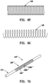
- the helical coil 140 may have a relaxed or low energy state in which adjacent coils contact one another with little or no gaps between the adjacent coils, e.g., as shown in FIG. 6F .
- the helical coil 140 may be stretched longitudinally to create gaps or spaces between adjacent coils, e.g., having a substantially uniform or other desired spacing, as shown in FIG. 6G .
- the helical coil 140 may then be embedded within or around base material (not shown) to provide a self-sealing structure. When the helical coil 140 is released after being embedded in the base material, the helical coil 140 will be biased to return to its low energy state.
- the helical coil 140 may apply a primarily axially compressive force to the base material (and to the underlying graft body 112 given the compressive force and greater stiffness of the helical coil 140 compared to the material of the graft body 112), which may enhance sealing when a needle or other device is introduced through the structure.
- the helical coil 140 may be sized to apply a radially compressive force to the base material 142, e.g., by sizing the helical coil 140 to have a relaxed or low energy diameter smaller than the graft body 112.
- the helical coil 140 may be embedded within the base material 142 in a relaxed and/or other low energy state, e.g., such that the helical coil 140 does not impose a radial and/or axial compressive force to the base material 142.
- Such a configuration may provide support for the internal lumen 116 of the graft body 112, e.g., to prevent the lumen 116 from being crushed when external pressure is applied, e.g., externally to the patient's skin overlying the graft 110.
- the base material may be formed directly around the graft body 112 and helical coil 140, e.g., by placing the helical coil 140 (in its stretched and/or radially expanded state) and desired length of the graft body 112 within a cavity of a mold and filling the cavity with base material.
- one or more layers of base material e.g., in sheet or tubular form, may be wrapped, slid, or otherwise applied around the graft body 112, e.g., a first layer between the helical coil 140 and the graft body 112 and a second layer over the helical coil 140 (not shown).
- the base material may be cured, heated, and/or otherwise processed to embed the helical coil 140 within the base material and/or to attach the base material and helical coil 140 to the graft body 112.
- an outer layer (not shown) may be applied over the base material after curing, e.g., an ePTFE sleeve similar to that shown in FIG. 2B and/or fabric may be applied over exposed surfaces to provide a desired finish for the cannulation region 30.
- the helical coil 140 may be embedded (again in its stretched state) within base material formed into a tubular sleeve, and then applied over and substantially permanently attached to the graft body 112, e.g., by bonding with adhesive, fusing, and the like, as described in the applications incorporated by reference herein.
- fabric may be applied over exposed surfaces before attaching the sleeve to the graft body 112 or an outer layer (not shown) may be applied over the sleeve after attachment to the graft body 112. Additional information regarding methods for forming a cannulation region including the helical coil 140 embedded within base material may be found in the applications incorporated by reference herein.
- FIGS. 7A-7C show another embodiment of a tubular graft 110" that includes a cannulation region 130" on a graft body 112, including first and second helical coils 140a," 140b" embedded within base material 142.”
- the cannulation region 130" may include an outer sleeve 144" and/or fabric covering, similar to other embodiments herein. As best seen in FIGS.
- the first helical coil 140a" has windings extending in a first helical direction
- the second helical coil 140b" has windings extending in a second helical direction opposite the first direction.
- the second helical coil 140b" has a diameter greater than the first helical coil 140a" such that the second helical coil 140b" may be positioned concentrically around the first helical coil 140a" (i.e., without braiding the helical coils together).
- the diameters may be set such that the second helical coil 140b" may contact the first helical coil 140a" at overlap points, or, alternatively, the second helical coil 140b" may be spaced apart from the first helical coil 140a” such that base material 142" flows or is otherwise located between the helical coils 140" to space them apart from one another.
- This configuration may provide more uniform axial compression along the cannulation region 130" since any torsional forces between the helical coils may cancel each other out.
- the overlapping helical coils 140" may provide a more uniform outer surface, e.g., preventing the base material 142" from bulging outwardly between the helical coils 140.”
- a cannulation region 130′′′ may be provided on a tubular graft 110"' that includes two helical coils 140′′′ with windings that extend in the same helical direction, i.e., with a second helical coil 140b′′′ disposed concentrically around a first helical coil 140a'" as shown in FIG. 8D .
- the windings of the second helical coil 140b′′′ may be axially aligned with windings of the first helical coil 140a′′′ (in phase) or they may be offset from one another (out of phase), as desired.
- two (or more) helical coils may be embedded together within the base material that have the same relaxed diameter but are offset axially from one another, e.g., by a half period or other desired spacing.
- a tubular graft 110 may be implanted within a patient's body, e.g., within the patient's forearm to provide arterial and venous access via cannulation regions 130 (including one or more helical coils 140 embedded in base material 142).
- a needle and/or other device may be introduced through the patient's skin overlying the graft 110, and directed through one of the cannulation regions 130 into the lumen 116.
- the cannulation region 130 includes a helical coil 140, as shown in FIG. 6A (or multiple coils 140" or 140′′′ as shown in FIGS.
- the needle may pass through one of the gaps between the spaced apart windings into the lumen of the graft body 112.
- the helical coil(s) 140 140,” 140′′′
- the axial compressive force applied by the helical coil(s) 140 140, 140′′′
- the base material 142 142, 142′′′
- the helical coil(s) 140 may prevent accidental leakage from graft 110, e.g., subcutaneous or subdermal bleeding resulting from infiltration, if the needle is accidentally inserted entirely through the graft body 112 and out the opposite side of the cannulation region 130 since the helical coil(s) 140 also applies an axial compressive force along the posterior side of the cannulation region 130.
- FIGS. 9A-9D still another embodiment of a reinforcement member is shown, namely a zigzag member 240 that extends along the length of a cannulation region of a tubular graft (or alternatively, the zigzag member 240 may be embedded in base material for a patch, similar to other embodiments herein), such as the cannulation regions 30 shown in FIG. 1 .
- the zigzag member 240 may be wrapped or otherwise positioned around the outer surface of a tubular graft body 212 and then embedded within or surrounding base material 242, e.g., silicone or other elastomeric material, similar to other embodiments herein and in the applications incorporated by reference herein.
- the zigzag member 240 includes alternating loops (e.g., peaks 240a and valleys 240b) that extend at least partially around the circumference of the graft body 212 and alternate along the length of the cannulation region.
- the loops 240a, 240b may define an arc orthogonal to the longitudinal axis 218 corresponding to an outer diameter of the graft body 212 with the arc length being a predetermined portion of the entire circumference.
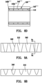
- FIG. 9C shows a cross-section of the zigzag member 240 embedded in base material 242 that extends only partially around the circumference of the graft body 212 (shown in phantom), e.g., thereby defining an arc angle ⁇ , e.g., between about 180-360° or between about 180-300°, around the circumference.
- the resulting cannulation region may only extend partially around the device body 212 and so, during implantation, the resulting tubular graft 10 may be implanted to orient the cannulation region anteriorly, i.e., towards the skin through which the cannulation region would be accessed.
- FIGS. 10A-10D another embodiment is shown that includes a pair of reinforcement members 240(1), 240(2) embedded within base material 242 and attached around a tubular graft body 212 to provide a cannulation region 230 (or embedded within base material for a patch, similar to other embodiments herein).
- Each reinforcement member 240 may be formed as a zigzag member similar to that shown in FIG. 9D , i.e., including alternating loops (e.g., peaks 240a and valleys 240b) that extend at least partially around the circumference of the graft body 212 and alternate along the length of the cannulation region.
- one or both zigzag member 240 may define a more complicated repeating pattern, e.g., having a shape similar to the zigzag member 340 shown in FIG. 11 , which defines nonlinear peaks 340a and valleys 340b.
- This alternative may provide the ability to alter the amount of compression along the arc of the pattern or influence the final geometry of the lumen.
- more complicated shapes may allow for controlling the degree of compression in any location along the cannulation region 230 and/or control the specific geometry of the areas not covered by the zigzag member 340 to facilitate minimized contact between a needle and the zigzag member 340.
- the first zigzag member 240(1) defines a first radius of curvature that is larger than the outer diameter of the graft body 212 and the second zigzag member 240(2) defines a second radius of curvature that is larger than the first radius such that the second zigzag member 240(2) is spaced apart radially outwardly from the first zigzag member 240(1), e.g., by a desired distance ⁇ between about zero and five millimeters (0-5.0 mm).
- the zigzag members 240 may be biased to the same diameter but may be offset axially from one another, e.g., by half a period or other desired spacing.
- the zigzag members 240 may be offset axially from one another, e.g., by half a period, such that the peaks and valleys are spaced uniformly along the cannulation region.
- Providing overlapping zigzag members 240 may provide more uniform compressive forces to the base material 242, may reduce bulging, and/or may provide greater wire density to the base material 242, which may enhance self-sealing of the cannulation region after being punctured, similar to other embodiments described elsewhere herein.
- having inner and outer zigzag members 240 may provide more uniform compressive, i.e., sealing forces, through the thickness of the base material 242.
- the properties of the inner and outer zigzag members 240 may be varied, i.e., with the outer zigzag member 240(2) having different elasticities, thicknesses, and/or other mechanical properties, e.g., to provide different compliances between the zigzag members 240, which may vary the properties towards the inner and outer surfaces of the cannulation region 230.
- the shape and/or other mechanical properties of the zigzag members 240 may be varied along their lengths, e.g., to provide different compliances and/or other properties along the length of the cannulation region 230.
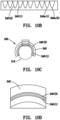
- FIGS. 12A-12F an exemplary embodiment of a self-sealing patch 430 is shown that includes a plurality of reinforcement elements 440 embedded within base material 442, e.g., similar to the cannulation regions described above.
- the patch 430 is an elongate body including first and second ends 432 and defining a "C" shaped cross-section that includes opposing side edges 434 extending between the opposite ends 432, thereby defining an inner lumen or recess 436.
- the patch 430 may be formed as a cuff, defining an arc greater than one hundred eighty degrees (180°), e.g., between about 180-360° or between about 180-300°, sized to receive a tubular structure (not shown) within the recess 436.
- the patch 430 may have a substantially planar or curved shape (not shown), e.g., such that an inner surface of the patch 430 may be attached to a tissue or other body structure, as described in the applications incorporated by reference herein.
- the reinforcement elements 440 and base material 442 may be sufficiently flexible such that the side edges 434 may be separated to allow the patch 430 to be positioned over and around a tubular structure, such as a tubular graft (not shown), e.g., similar to the grafts described elsewhere herein and in the applications incorporated by reference herein.
- a tubular structure such as a tubular graft (not shown), e.g., similar to the grafts described elsewhere herein and in the applications incorporated by reference herein.
- the reinforcement elements 440 include an inner zigzag member 440a and an outer zigzag member 440b.
- Each zigzag member 440 may include alternating loops (e.g., peaks and valleys) that extend at least partially around the circumference of the patch 430 and alternate along a desired length of the patch 430.
- adjacent peaks and valleys of each zigzag member 440 are spaced apart axially, and the zigzag members 440 are offset axially from one another such that the peaks of one zigzag member 440a along one side edge 434 are axially aligned with the valleys of the other zigzag member 440b on the opposite side edge 434.
- the outer member 440b may have a larger diameter than the inner member 440a such that the outer member 440b may be disposed concentrically around the inner member 440a (i.e., without braiding or otherwise overlapping the inner member 440a over the outer member 440b).
- the outer member 440b may be spaced apart from the inner member 440a, i.e., such that base material 442 is disposed between the members 440, or, the outer member 440b may contact the inner member 440a, e.g., at overlap points 441 at the top of the patch 430, best seen in FIG. 12B .
- FIGS. 13A-13F another exemplary embodiment of a self-sealing patch 530 is shown that includes a plurality of reinforcement elements 540 embedded within base material 542.
- the patch 530 is an elongate body including first and second ends 532 and defining a "C" shaped cross-section that includes opposing side edges 534 extending between the opposite ends 532, thereby defining an inner lumen or recess 536.
- the side edges 534 may be beveled and/or rounded at the ends 532, e.g., to facilitate positioning the patch 530 over a tubular structure.
- the reinforcement elements 540 also include an inner zigzag member 540a and an outer zigzag member 540b disposed concentrically around the inner member 540a.
- each zigzag member 540 may include alternating loops (e.g., peaks and valleys) that extend at least partially around the circumference of the patch 530 and alternate along a desired length of the patch 530, similar to the previous embodiments.
- the arc of the patch 530 is smaller than that of the patch 430 and the zigzag members 540 have shorter circumferential amplitudes along the length of the patch 530 than the zigzag members 440.
- the shape and/or period of the zigzag members 440, 540 may be varied to provide desired compliances and/or other mechanical properties, as described previously for other reinforcement elements.
Landscapes
- Health & Medical Sciences (AREA)
- Heart & Thoracic Surgery (AREA)
- Engineering & Computer Science (AREA)
- Biomedical Technology (AREA)
- Life Sciences & Earth Sciences (AREA)
- Vascular Medicine (AREA)
- Public Health (AREA)
- Veterinary Medicine (AREA)
- Animal Behavior & Ethology (AREA)
- General Health & Medical Sciences (AREA)
- Cardiology (AREA)
- Transplantation (AREA)
- Oral & Maxillofacial Surgery (AREA)
- Pulmonology (AREA)
- Hematology (AREA)
- Anesthesiology (AREA)
- Gastroenterology & Hepatology (AREA)
- Biophysics (AREA)
- Urology & Nephrology (AREA)
- Emergency Medicine (AREA)
- Epidemiology (AREA)
- Prostheses (AREA)
- Rigid Pipes And Flexible Pipes (AREA)
Claims (15)
- Manchon auto-obturant (230, 430, 530) implantable dans le corps d'un patient, comprenant :un matériau de base (242, 442, 542) définissant une première extrémité, une seconde extrémité, et ayant une section transversale en forme de « C » définissant des bords opposés (434, 534) s'étendant entre les première et seconde extrémités (532) ; etdes premier et second organes de renforcement (240, 340, 440, 540) incorporés dans le matériau de base (242, 442, 542), le premier organe de renforcement s'étendant axialement le long d'une première longueur et comportant des éléments qui s'étendent au moins partiellement autour d'une circonférence du matériau de base (242, 442, 542), le second organe de renforcement s'étendant axialement le long de la première longueur et comportant des éléments qui s'étendent au moins partiellement autour de la circonférence du matériau de base (242, 442, 542), et le second organe de renforcement est espacé radialement du premier organe de renforcement,dans lequel les premier et second organes de renforcement comprennent des premier et second organes en zigzag qui s'étendent axialement le long de la première longueur et comportent des boucles alternées définissant des pics et des vallées qui s'étendent au moins partiellement autour de la circonférence du corps tubulaire, etdans lequel les premier et second organes en zigzag sont déphasés l'un par rapport à l'autre de telle sorte que des pics du premier organe en zigzag sont disposés à l'opposé de vallées du second organe en zigzag le long des bords opposés (434, 534).
- Manchon selon la revendication 1, dans lequel les premier et second organes de renforcement ne sont pas en contact l'un avec l'autre.
- Manchon selon la revendication 1, dans lequel le matériau de base est situé entre les premier et second organes de renforcement.
- Manchon selon la revendication 1, dans lequel le second organe de renforcement entre en contact avec le premier organe de renforcement au niveau de points où le second organe de renforcement chevauche le premier organe de renforcement.
- Manchon selon la revendication 1, dans lequel les premier et second organes en zigzag sont déphasés l'un par rapport à l'autre de telle sorte que le second organe en zigzag entre en contact avec le premier organe en zigzag au niveau de points où le second organe en zigzag chevauche le premier organe en zigzag.
- Manchon selon la revendication 1, dans lequel les premier et second organes de renforcement sont configurés pour appliquer des forces de compression axiales au matériau de base.
- Manchon selon une quelconque revendication précédente, dans lequel la section transversale en forme de « C » définit un arc supérieur à cent quatre-vingts degrés (180°).
- Manchon selon une quelconque revendication précédente, dans lequel la section transversale en forme de « C » définit un arc entre 180 et 300°.
- Manchon selon une quelconque revendication précédente, dans lequel les pics du premier organe en zigzag sont disposés à proximité adjacente d'un premier bord latéral des bords opposés et les vallées du second organe en zigzag sont disposées à proximité adjacente d'un second bord latéral des bords opposés qui sont opposés aux pics du premier organe en zigzag.
- Manchon selon l'une quelconque des revendications 1 à 8, dans lequel les pics et vallées adjacents des premier et second organes en zigzag sont espacés axialement, les premier et second organes en zigzag étant décalés axialement l'un par rapport à l'autre de telle sorte que les pics du premier organe en zigzag (440a) le long d'un bord latéral (434) sont alignés axialement avec les vallées du second organe en zigzag (440b) sur le bord latéral opposé (434).
- Manchon selon une quelconque revendication précédente, dans lequel les premier et second organes en zigzag sont décalés axialement l'un par rapport à l'autre, de telle sorte que les pics et les vallées sont espacés uniformément le long d'une région de canulation.
- Manchon selon une quelconque revendication précédente, dans lequel un tissu est appliqué sur toutes les surfaces exposées du matériau de base.
- Greffon tubulaire (10), comprenant un manchon selon l'une quelconque des revendications précédentes fixé autour d'un corps de greffon tubulaire (212) pour fournir une région de canulation (230).
- Greffon tubulaire (10), comprenant :un corps tubulaire allongé (12) comportant une première extrémité, une seconde extrémité, et une lumière s'étendant entre les première et seconde extrémités ; etune première région auto-obturante (30) entourant au moins partiellement une première longueur du corps tubulaire, la région auto-obturante comprenant un manchon selon l'une quelconque des revendications 1 à 12.
- Greffon tubulaire selon la revendication 13 ou 14, dans lequel le matériau de base comprend un matériau élastomère.
Priority Applications (1)
| Application Number | Priority Date | Filing Date | Title |
|---|---|---|---|
| EP24179796.8A EP4424341A3 (fr) | 2016-04-25 | 2017-04-21 | Greffons tubulaires auto-obturants, patches et leurs procédés de fabrication et d'utilisation |
Applications Claiming Priority (3)
| Application Number | Priority Date | Filing Date | Title |
|---|---|---|---|
| US201662327328P | 2016-04-25 | 2016-04-25 | |
| US201762471867P | 2017-03-15 | 2017-03-15 | |
| PCT/US2017/028939 WO2017189364A1 (fr) | 2016-04-25 | 2017-04-21 | Greffons tubulaires auto-obturants, patches et leurs procédés de fabrication et d'utilisation |
Related Child Applications (1)
| Application Number | Title | Priority Date | Filing Date |
|---|---|---|---|
| EP24179796.8A Division EP4424341A3 (fr) | 2016-04-25 | 2017-04-21 | Greffons tubulaires auto-obturants, patches et leurs procédés de fabrication et d'utilisation |
Publications (4)
| Publication Number | Publication Date |
|---|---|
| EP3448311A1 EP3448311A1 (fr) | 2019-03-06 |
| EP3448311A4 EP3448311A4 (fr) | 2020-01-01 |
| EP3448311B1 true EP3448311B1 (fr) | 2024-06-05 |
| EP3448311C0 EP3448311C0 (fr) | 2024-06-05 |
Family
ID=60088316
Family Applications (2)
| Application Number | Title | Priority Date | Filing Date |
|---|---|---|---|
| EP17790155.0A Active EP3448311B1 (fr) | 2016-04-25 | 2017-04-21 | Greffons tubulaires auto-obturants |
| EP24179796.8A Withdrawn EP4424341A3 (fr) | 2016-04-25 | 2017-04-21 | Greffons tubulaires auto-obturants, patches et leurs procédés de fabrication et d'utilisation |
Family Applications After (1)
| Application Number | Title | Priority Date | Filing Date |
|---|---|---|---|
| EP24179796.8A Withdrawn EP4424341A3 (fr) | 2016-04-25 | 2017-04-21 | Greffons tubulaires auto-obturants, patches et leurs procédés de fabrication et d'utilisation |
Country Status (6)
| Country | Link |
|---|---|
| US (3) | US10596017B2 (fr) |
| EP (2) | EP3448311B1 (fr) |
| JP (2) | JP7222881B2 (fr) |
| CN (3) | CN208319684U (fr) |
| ES (1) | ES2983672T3 (fr) |
| WO (1) | WO2017189364A1 (fr) |
Families Citing this family (28)
| Publication number | Priority date | Publication date | Assignee | Title |
|---|---|---|---|---|
| EP3448311B1 (fr) * | 2016-04-25 | 2024-06-05 | Solinas Medical, Inc. | Greffons tubulaires auto-obturants |
| US11065377B2 (en) | 2017-03-31 | 2021-07-20 | InnAVasc Medical, Inc. | Apparatus and method for cannulation of vascular access graft |
| US12017032B1 (en) | 2017-11-13 | 2024-06-25 | Sbr Innovations, Llc | Arteriovenous graft and method of using thereof |
| US10850084B1 (en) * | 2017-12-15 | 2020-12-01 | Simon B. Rayhanabad | Arteriovenous graft and method of providing dialysis |
| US10641427B2 (en) | 2018-04-03 | 2020-05-05 | Mueller International, Llc | Stents and methods for repairing pipes |
| IT201800007540A1 (it) * | 2018-07-26 | 2020-01-26 | Eurosets Srl | Cannula per il drenaggio di vasi sanguigni |
| KR20200033757A (ko) | 2018-09-20 | 2020-03-30 | 디퍼이 신테스 프로덕츠, 인코포레이티드 | 형상화된 와이어를 갖는 스텐트 |
| IT201900000981A1 (it) * | 2019-01-23 | 2020-07-23 | Giancarlo Salsano | Dispositivo endovascolare per fistole disfunzionali |
| US11353154B2 (en) | 2019-02-19 | 2022-06-07 | Mueller International, Llc | Stent springs and stents for repairing pipes |
| US11187366B2 (en) | 2019-03-15 | 2021-11-30 | Mueller International, Llc | Stent for repairing a pipe |
| US11079058B2 (en) | 2019-03-15 | 2021-08-03 | Mueller International , LLC | Stent with coiled spring |
| US11766539B2 (en) | 2019-03-29 | 2023-09-26 | Incept, Llc | Enhanced flexibility neurovascular catheter |
| US11326731B2 (en) | 2019-04-24 | 2022-05-10 | Mueller International, Llc | Pipe repair assembly |
| US11802646B2 (en) | 2019-08-09 | 2023-10-31 | Mueller International, Llc | Pipe repair device |
| US11391405B2 (en) | 2019-08-09 | 2022-07-19 | Mueller International, Llc | Deployment probe for pipe repair device |
| US11439799B2 (en) | 2019-12-18 | 2022-09-13 | Imperative Care, Inc. | Split dilator aspiration system |
| US20230248498A1 (en) | 2019-12-18 | 2023-08-10 | Imperative Care, Inc. | Manually rotatable thrombus engagement tool |
| CN110975038B (zh) * | 2019-12-23 | 2022-05-17 | 余强 | 一种用于血液透析的血管造漏支架 |
| JP7581357B2 (ja) * | 2020-02-03 | 2024-11-12 | ボストン サイエンティフィック サイムド,インコーポレイテッド | ステント |
| CN118925025A (zh) * | 2020-03-10 | 2024-11-12 | 因普瑞缇夫护理公司 | 增强的柔韧性的神经血管导管 |
| EP4552680A3 (fr) * | 2020-03-11 | 2025-07-16 | Stryker Corporation | Cathéter à fentes avec éléments de remplissage |
| CN114870201B (zh) * | 2021-02-05 | 2025-10-10 | 微创神通医疗科技(上海)有限公司 | 一种导管加强层和导管 |
| CA3211866A1 (fr) * | 2021-03-26 | 2022-09-29 | Shawn M. GAGE | Appareil et procede d'implantation d'une greffe arterio-veineuse |
| CA3229710A1 (fr) * | 2021-09-15 | 2023-03-23 | W. L. Gore & Associates, Inc. | Gaine d'introduction endoluminale avec couches polymeres et elements de support entre celles-ci |
| CN114869541B (zh) * | 2022-03-10 | 2026-03-31 | 生纳科技(上海)有限公司 | 抗弯折人工血管及其制备方法 |
| CA3245926A1 (fr) * | 2022-03-16 | 2023-09-21 | W. L. Gore & Associates, Inc. | Systèmes et méthodes de greffon d'accès |
| US12171917B1 (en) | 2024-01-08 | 2024-12-24 | Imperative Care, Inc. | Devices for blood capture and reintroduction during aspiration procedure |
| WO2026007049A1 (fr) * | 2024-07-04 | 2026-01-08 | 温州医科大学附属第一医院 | Structure déchirable |
Family Cites Families (81)
| Publication number | Priority date | Publication date | Assignee | Title |
|---|---|---|---|---|
| US3814137A (en) | 1973-01-26 | 1974-06-04 | Baxter Laboratories Inc | Injection site for flow conduits containing biological fluids |
| US6436135B1 (en) | 1974-10-24 | 2002-08-20 | David Goldfarb | Prosthetic vascular graft |
| US4428364A (en) | 1979-04-11 | 1984-01-31 | Dow Corning Corporation | Self-sealing injection button and method of making same |
| US4564915A (en) | 1980-04-11 | 1986-01-14 | Ampex Corporation | YIQ Computer graphics system |
| US4604762A (en) * | 1981-02-13 | 1986-08-12 | Thoratec Laboratories Corporation | Arterial graft prosthesis |
| US4619641A (en) | 1984-11-13 | 1986-10-28 | Mount Sinai School Of Medicine Of The City University Of New York | Coaxial double lumen anteriovenous grafts |
| US4645495A (en) | 1985-06-26 | 1987-02-24 | Vaillancourt Vincent L | Vascular access implant needle patch |
| US4816339A (en) | 1987-04-28 | 1989-03-28 | Baxter International Inc. | Multi-layered poly(tetrafluoroethylene)/elastomer materials useful for in vivo implantation |
| US5100422A (en) | 1989-05-26 | 1992-03-31 | Impra, Inc. | Blood vessel patch |
| US5866217A (en) | 1991-11-04 | 1999-02-02 | Possis Medical, Inc. | Silicone composite vascular graft |
| FR2688401B1 (fr) | 1992-03-12 | 1998-02-27 | Thierry Richard | Endoprothese expansible pour organe tubulaire humain ou animal, et outil de mise en place. |
| US5647855A (en) | 1992-05-06 | 1997-07-15 | Trooskin; Stanley Z. | Self-healing diaphragm in a subcutaneous infusion port |
| US5342387A (en) * | 1992-06-18 | 1994-08-30 | American Biomed, Inc. | Artificial support for a blood vessel |
| US5562617A (en) | 1994-01-18 | 1996-10-08 | Finch, Jr.; Charles D. | Implantable vascular device |
| US5556414A (en) * | 1995-03-08 | 1996-09-17 | Wayne State University | Composite intraluminal graft |
| US5667523A (en) * | 1995-04-28 | 1997-09-16 | Impra, Inc. | Dual supported intraluminal graft |
| US5800512A (en) | 1996-01-22 | 1998-09-01 | Meadox Medicals, Inc. | PTFE vascular graft |
| US5928279A (en) | 1996-07-03 | 1999-07-27 | Baxter International Inc. | Stented, radially expandable, tubular PTFE grafts |
| AU4489197A (en) | 1996-09-20 | 1998-04-14 | Sid D. Fleischman | Radially expanding prostheses and systems for their deployment |
| JP3815828B2 (ja) * | 1996-10-02 | 2006-08-30 | 株式会社パイオラックス | 管状器官の治療具 |
| US5906596A (en) | 1996-11-26 | 1999-05-25 | Std Manufacturing | Percutaneous access device |
| US6494904B1 (en) * | 1996-12-27 | 2002-12-17 | Ramus Medical Technologies | Method and apparatus for forming vascular prostheses |
| US6007516A (en) | 1997-01-21 | 1999-12-28 | Vasca, Inc. | Valve port and method for vascular access |
| US6102884A (en) | 1997-02-07 | 2000-08-15 | Squitieri; Rafael | Squitieri hemodialysis and vascular access systems |
| IL132195A0 (en) | 1997-04-11 | 2001-03-19 | Transvascular Inc | Method and apparatus for transmyocardial direct coronary revascularization |
| US5984955A (en) | 1997-09-11 | 1999-11-16 | Wisselink; Willem | System and method for endoluminal grafting of bifurcated or branched vessels |
| US5931865A (en) * | 1997-11-24 | 1999-08-03 | Gore Enterprise Holdings, Inc. | Multiple-layered leak resistant tube |
| US6544167B2 (en) | 1998-05-01 | 2003-04-08 | Correstore, Inc. | Ventricular restoration patch |
| US6261257B1 (en) | 1998-05-26 | 2001-07-17 | Renan P. Uflacker | Dialysis graft system with self-sealing access ports |
| US5944688A (en) | 1998-07-20 | 1999-08-31 | Lois; William A | Implantable hemodialysis access port assembly |
| AU774924B2 (en) | 1999-01-22 | 2004-07-15 | W.L. Gore & Associates, Inc. | Covered endoprosthesis and delivery system |
| US7892246B2 (en) | 1999-07-28 | 2011-02-22 | Bioconnect Systems, Inc. | Devices and methods for interconnecting conduits and closing openings in tissue |
| US6319279B1 (en) * | 1999-10-15 | 2001-11-20 | Edwards Lifesciences Corp. | Laminated self-sealing vascular access graft |
| CA2407643C (fr) | 2000-04-26 | 2009-06-30 | Std Manufacturing, Inc. | Dispositif d'acces pour hemodialyse implantable |
| US6623510B2 (en) | 2000-12-07 | 2003-09-23 | Integrated Vascular Systems, Inc. | Closure device and methods for making and using them |
| US6645242B1 (en) | 2000-12-11 | 2003-11-11 | Stephen F. Quinn | Bifurcated side-access intravascular stent graft |
| US6553167B2 (en) | 2001-06-04 | 2003-04-22 | Corning Cable Systems Llc | Fiber optic cables having ultra-low shrinking filaments and methods of making the same |
| DE10219014A1 (de) * | 2002-04-27 | 2003-11-13 | Ruesch Willy Gmbh | Selbstexpandierbarer Stent |
| EP1565220A4 (fr) | 2002-10-09 | 2011-08-31 | Circuport Inc | Orifice d'acces implantable pour dialyse |
| US7452374B2 (en) | 2003-04-24 | 2008-11-18 | Maquet Cardiovascular, Llc | AV grafts with rapid post-operative self-sealing capabilities |
| US7438721B2 (en) | 2003-04-25 | 2008-10-21 | Medtronic Vascular, Inc. | Universal modular stent graft assembly to accommodate flow to collateral branches |
| US20050131520A1 (en) | 2003-04-28 | 2005-06-16 | Zilla Peter P. | Compliant blood vessel graft |
| US7762977B2 (en) | 2003-10-08 | 2010-07-27 | Hemosphere, Inc. | Device and method for vascular access |
| WO2005037138A2 (fr) | 2003-10-14 | 2005-04-28 | Peacock James C Iii | Systeme et methode de traitement d'anevrisme |
| GB0402103D0 (en) | 2004-02-02 | 2004-03-03 | Hengelmolen Rudy | Tubular graft |
| US7297158B2 (en) * | 2004-06-14 | 2007-11-20 | Thoratec Corporation | Multilayer composite vascular access graft |
| US20060025848A1 (en) | 2004-07-29 | 2006-02-02 | Jan Weber | Medical device having a coating layer with structural elements therein and method of making the same |
| EP1791496B1 (fr) * | 2004-08-31 | 2019-07-31 | C.R. Bard, Inc. | Greffe en polytetrafluorethylene (ptfe) auto-etanche a resistance au tortillement |
| US7255682B1 (en) | 2004-09-09 | 2007-08-14 | Bartol Jr Robert J | Spot locator device |
| DE102004052408B3 (de) | 2004-10-25 | 2005-12-15 | ADEVA - medical Gesellschaft für Entwicklung und Vertrieb von medizinischen Implantat-Artikeln mbH | Gewebekonnektor |
| US8029563B2 (en) | 2004-11-29 | 2011-10-04 | Gore Enterprise Holdings, Inc. | Implantable devices with reduced needle puncture site leakage |
| US20070088336A1 (en) | 2005-10-17 | 2007-04-19 | Dalton Michael J | Implantable drug delivery depot for subcutaneous delivery of fluids |
| US8163002B2 (en) * | 2005-11-14 | 2012-04-24 | Vascular Devices Llc | Self-sealing vascular graft |
| US20070167901A1 (en) | 2005-11-17 | 2007-07-19 | Herrig Judson A | Self-sealing residual compressive stress graft for dialysis |
| CN101384228A (zh) | 2005-11-17 | 2009-03-11 | 海默斯菲尔有限公司 | 用于透析的自封式残余压缩应力移植物 |
| US20070265584A1 (en) | 2006-02-15 | 2007-11-15 | Hickman Robert O | Venous prosthesis and vascular graft with access port |
| US20130190676A1 (en) * | 2006-04-20 | 2013-07-25 | Limflow Gmbh | Devices and methods for fluid flow through body passages |
| US7727143B2 (en) | 2006-05-31 | 2010-06-01 | Allergan, Inc. | Locator system for implanted access port with RFID tag |
| US7780590B2 (en) | 2006-05-31 | 2010-08-24 | Allergan, Inc. | Method for locating an implanted fluid access port |
| US20070299538A1 (en) | 2006-06-26 | 2007-12-27 | Roeber Peter J | Ease of use tissue repair patch |
| US20080009889A1 (en) | 2006-07-05 | 2008-01-10 | Pokorney James L | Conduit cuff |
| US20080208325A1 (en) * | 2007-02-27 | 2008-08-28 | Boston Scientific Scimed, Inc. | Medical articles for long term implantation |
| US20080243080A1 (en) | 2007-03-27 | 2008-10-02 | Chang David W | Method and apparatus for vascular access |
| JP2009022511A (ja) * | 2007-07-19 | 2009-02-05 | National Cardiovascular Center | 人工血管 |
| US8906081B2 (en) * | 2007-09-13 | 2014-12-09 | W. L. Gore & Associates, Inc. | Stented vascular graft |
| US8486131B2 (en) | 2007-12-15 | 2013-07-16 | Endospan Ltd. | Extra-vascular wrapping for treating aneurysmatic aorta in conjunction with endovascular stent-graft and methods thereof |
| US9440058B2 (en) | 2007-12-17 | 2016-09-13 | Cook Medical Technologies, LLC | Device for enabling repeated access to a vessel |
| US8079973B2 (en) | 2008-03-05 | 2011-12-20 | Hemosphere Inc. | Vascular access system |
| US20110295181A1 (en) | 2008-03-05 | 2011-12-01 | Hemosphere, Inc. | Implantable and removable customizable body conduit |
| WO2010011995A1 (fr) | 2008-07-25 | 2010-01-28 | Roger Alan Mason | Dispositif d'accès vasculaire |
| WO2010015001A1 (fr) | 2008-08-01 | 2010-02-04 | The Methodist Hospital Research Institute | Greffes d'hémodialyse et procédés pour localiser et identifier le placement de ceux-ci |
| US20120310324A1 (en) | 2009-11-04 | 2012-12-06 | Endospan Ltd. | Treatment of a main body lumen in the vicinity of a branching body lumen |
| EP2533730A1 (fr) | 2010-02-10 | 2012-12-19 | Apertomed, L.L.C. | Méthodes, systèmes et dispositifs pour le traitement de l'insuffisance veineuse cérébrospinale et de la sclérose en plaques |
| ES2656939T3 (es) | 2010-03-09 | 2018-03-01 | Solinas Medical Inc. | Dispositivos de cierre automático |
| EP2753376B1 (fr) | 2011-09-06 | 2015-07-01 | Hemosphere Inc. | Système d'accès vasculaire doté d'un connecteur |
| US9539360B2 (en) | 2011-10-07 | 2017-01-10 | W. L. Gore & Associaes, Inc. | Puncturable and resealable graft |
| EP2983625B1 (fr) * | 2013-04-13 | 2024-02-14 | Solinas Medical, Inc. | Dispositifs et appareil à fermeture automatique et leurs procédés de fabrication et de pose |
| US20150025437A1 (en) | 2013-07-18 | 2015-01-22 | Cryolife, Inc. | Vascular access system with connector |
| EP3046507A4 (fr) * | 2013-09-20 | 2017-03-15 | Neograft Technologies, Inc. | Greffons artificiels pourvus de structures de support et systèmes et procédés apparentés |
| US10682453B2 (en) * | 2013-12-20 | 2020-06-16 | Merit Medical Systems, Inc. | Vascular access system with reinforcement member |
| EP3448311B1 (fr) * | 2016-04-25 | 2024-06-05 | Solinas Medical, Inc. | Greffons tubulaires auto-obturants |
-
2017
- 2017-04-21 EP EP17790155.0A patent/EP3448311B1/fr active Active
- 2017-04-21 ES ES17790155T patent/ES2983672T3/es active Active
- 2017-04-21 US US15/494,254 patent/US10596017B2/en active Active
- 2017-04-21 EP EP24179796.8A patent/EP4424341A3/fr not_active Withdrawn
- 2017-04-21 JP JP2019506611A patent/JP7222881B2/ja active Active
- 2017-04-21 WO PCT/US2017/028939 patent/WO2017189364A1/fr not_active Ceased
- 2017-04-24 CN CN201720433259.4U patent/CN208319684U/zh not_active Expired - Fee Related
- 2017-04-24 CN CN201710270906.9A patent/CN107441615B/zh not_active Expired - Fee Related
- 2017-04-24 CN CN202110872340.3A patent/CN113856007B/zh not_active Expired - Fee Related
-
2020
- 2020-02-27 US US16/803,761 patent/US11602446B2/en active Active
-
2021
- 2021-10-27 JP JP2021175675A patent/JP7331063B2/ja active Active
-
2023
- 2023-03-01 US US18/116,197 patent/US12213898B2/en active Active
Also Published As
| Publication number | Publication date |
|---|---|
| US11602446B2 (en) | 2023-03-14 |
| US12213898B2 (en) | 2025-02-04 |
| EP4424341A3 (fr) | 2024-11-20 |
| WO2017189364A1 (fr) | 2017-11-02 |
| US20170304092A1 (en) | 2017-10-26 |
| CN107441615B (zh) | 2021-08-20 |
| ES2983672T3 (es) | 2024-10-24 |
| CN208319684U (zh) | 2019-01-04 |
| EP3448311A4 (fr) | 2020-01-01 |
| US20200206002A1 (en) | 2020-07-02 |
| CN113856007B (zh) | 2024-08-06 |
| CN107441615A (zh) | 2017-12-08 |
| EP4424341A2 (fr) | 2024-09-04 |
| JP2019514642A (ja) | 2019-06-06 |
| US10596017B2 (en) | 2020-03-24 |
| JP2022009596A (ja) | 2022-01-14 |
| JP7331063B2 (ja) | 2023-08-22 |
| CN113856007A (zh) | 2021-12-31 |
| EP3448311C0 (fr) | 2024-06-05 |
| US20230201013A1 (en) | 2023-06-29 |
| JP7222881B2 (ja) | 2023-02-15 |
| EP3448311A1 (fr) | 2019-03-06 |
Similar Documents
| Publication | Publication Date | Title |
|---|---|---|
| US12213898B2 (en) | Self-sealing tubular grafts, patches, and methods for making and using them | |
| US11826029B2 (en) | Self-closing devices and methods for making and using them | |
| JP4094684B2 (ja) | 単一または二又の管腔のための巻板移植片および作製と使用の方法 | |
| CN107530162B (zh) | 具有提高的柔韧性的支架移植物 | |
| CN102548506B (zh) | 分叉的高度顺从性医疗器械分支通路 | |
| JP6297023B2 (ja) | 耐キンク性ステントグラフト | |
| JP7604667B2 (ja) | 自己密閉窓を備えたインプラント可能な導管、ならびに関連するシステム及び方法 | |
| AU2023236127B2 (en) | Access graft systems and methods | |
| KR101691118B1 (ko) | 단부의 저항력이 강화된 의료용 스텐트 제조 방법 및 그 스텐트 |
Legal Events
| Date | Code | Title | Description |
|---|---|---|---|
| STAA | Information on the status of an ep patent application or granted ep patent |
Free format text: STATUS: THE INTERNATIONAL PUBLICATION HAS BEEN MADE |
|
| PUAI | Public reference made under article 153(3) epc to a published international application that has entered the european phase |
Free format text: ORIGINAL CODE: 0009012 |
|
| STAA | Information on the status of an ep patent application or granted ep patent |
Free format text: STATUS: REQUEST FOR EXAMINATION WAS MADE |
|
| 17P | Request for examination filed |
Effective date: 20181026 |
|
| AK | Designated contracting states |
Kind code of ref document: A1 Designated state(s): AL AT BE BG CH CY CZ DE DK EE ES FI FR GB GR HR HU IE IS IT LI LT LU LV MC MK MT NL NO PL PT RO RS SE SI SK SM TR |
|
| AX | Request for extension of the european patent |
Extension state: BA ME |
|
| DAV | Request for validation of the european patent (deleted) | ||
| DAX | Request for extension of the european patent (deleted) | ||
| REG | Reference to a national code |
Ref country code: DE Ref legal event code: R079 Free format text: PREVIOUS MAIN CLASS: A61F0002040000 Ipc: A61F0002070000 |
|
| A4 | Supplementary search report drawn up and despatched |
Effective date: 20191203 |
|
| RIC1 | Information provided on ipc code assigned before grant |
Ipc: A61F 2/88 20060101ALN20191127BHEP Ipc: A61M 1/36 20060101ALI20191127BHEP Ipc: A61F 2/07 20130101AFI20191127BHEP |
|
| STAA | Information on the status of an ep patent application or granted ep patent |
Free format text: STATUS: EXAMINATION IS IN PROGRESS |
|
| 17Q | First examination report despatched |
Effective date: 20230217 |
|
| GRAP | Despatch of communication of intention to grant a patent |
Free format text: ORIGINAL CODE: EPIDOSNIGR1 |
|
| STAA | Information on the status of an ep patent application or granted ep patent |
Free format text: STATUS: GRANT OF PATENT IS INTENDED |
|
| RIC1 | Information provided on ipc code assigned before grant |
Ipc: A61F 2/88 20060101ALN20231223BHEP Ipc: A61M 1/36 20060101ALI20231223BHEP Ipc: A61F 2/07 20130101AFI20231223BHEP |
|
| INTG | Intention to grant announced |
Effective date: 20240117 |
|
| GRAS | Grant fee paid |
Free format text: ORIGINAL CODE: EPIDOSNIGR3 |
|
| GRAA | (expected) grant |
Free format text: ORIGINAL CODE: 0009210 |
|
| STAA | Information on the status of an ep patent application or granted ep patent |
Free format text: STATUS: THE PATENT HAS BEEN GRANTED |
|
| AK | Designated contracting states |
Kind code of ref document: B1 Designated state(s): AL AT BE BG CH CY CZ DE DK EE ES FI FR GB GR HR HU IE IS IT LI LT LU LV MC MK MT NL NO PL PT RO RS SE SI SK SM TR |
|
| REG | Reference to a national code |
Ref country code: GB Ref legal event code: FG4D |
|
| REG | Reference to a national code |
Ref country code: CH Ref legal event code: EP |
|
| REG | Reference to a national code |
Ref country code: DE Ref legal event code: R096 Ref document number: 602017082428 Country of ref document: DE |
|
| REG | Reference to a national code |
Ref country code: IE Ref legal event code: FG4D |
|
| U01 | Request for unitary effect filed |
Effective date: 20240627 |
|
| U07 | Unitary effect registered |
Designated state(s): AT BE BG DE DK EE FI FR IT LT LU LV MT NL PT SE SI Effective date: 20240708 |
|
| PG25 | Lapsed in a contracting state [announced via postgrant information from national office to epo] |
Ref country code: HR Free format text: LAPSE BECAUSE OF FAILURE TO SUBMIT A TRANSLATION OF THE DESCRIPTION OR TO PAY THE FEE WITHIN THE PRESCRIBED TIME-LIMIT Effective date: 20240605 |
|
| PG25 | Lapsed in a contracting state [announced via postgrant information from national office to epo] |
Ref country code: GR Free format text: LAPSE BECAUSE OF FAILURE TO SUBMIT A TRANSLATION OF THE DESCRIPTION OR TO PAY THE FEE WITHIN THE PRESCRIBED TIME-LIMIT Effective date: 20240906 |
|
| REG | Reference to a national code |
Ref country code: ES Ref legal event code: FG2A Ref document number: 2983672 Country of ref document: ES Kind code of ref document: T3 Effective date: 20241024 |
|
| PG25 | Lapsed in a contracting state [announced via postgrant information from national office to epo] |
Ref country code: NO Free format text: LAPSE BECAUSE OF FAILURE TO SUBMIT A TRANSLATION OF THE DESCRIPTION OR TO PAY THE FEE WITHIN THE PRESCRIBED TIME-LIMIT Effective date: 20240905 Ref country code: HR Free format text: LAPSE BECAUSE OF FAILURE TO SUBMIT A TRANSLATION OF THE DESCRIPTION OR TO PAY THE FEE WITHIN THE PRESCRIBED TIME-LIMIT Effective date: 20240605 Ref country code: GR Free format text: LAPSE BECAUSE OF FAILURE TO SUBMIT A TRANSLATION OF THE DESCRIPTION OR TO PAY THE FEE WITHIN THE PRESCRIBED TIME-LIMIT Effective date: 20240906 Ref country code: RS Free format text: LAPSE BECAUSE OF FAILURE TO SUBMIT A TRANSLATION OF THE DESCRIPTION OR TO PAY THE FEE WITHIN THE PRESCRIBED TIME-LIMIT Effective date: 20240905 |
|
| PG25 | Lapsed in a contracting state [announced via postgrant information from national office to epo] |
Ref country code: PL Free format text: LAPSE BECAUSE OF FAILURE TO SUBMIT A TRANSLATION OF THE DESCRIPTION OR TO PAY THE FEE WITHIN THE PRESCRIBED TIME-LIMIT Effective date: 20240605 |
|
| PG25 | Lapsed in a contracting state [announced via postgrant information from national office to epo] |
Ref country code: IS Free format text: LAPSE BECAUSE OF FAILURE TO SUBMIT A TRANSLATION OF THE DESCRIPTION OR TO PAY THE FEE WITHIN THE PRESCRIBED TIME-LIMIT Effective date: 20241005 |
|
| PG25 | Lapsed in a contracting state [announced via postgrant information from national office to epo] |
Ref country code: CZ Free format text: LAPSE BECAUSE OF FAILURE TO SUBMIT A TRANSLATION OF THE DESCRIPTION OR TO PAY THE FEE WITHIN THE PRESCRIBED TIME-LIMIT Effective date: 20240605 |
|
| PG25 | Lapsed in a contracting state [announced via postgrant information from national office to epo] |
Ref country code: RO Free format text: LAPSE BECAUSE OF FAILURE TO SUBMIT A TRANSLATION OF THE DESCRIPTION OR TO PAY THE FEE WITHIN THE PRESCRIBED TIME-LIMIT Effective date: 20240605 Ref country code: SK Free format text: LAPSE BECAUSE OF FAILURE TO SUBMIT A TRANSLATION OF THE DESCRIPTION OR TO PAY THE FEE WITHIN THE PRESCRIBED TIME-LIMIT Effective date: 20240605 |
|
| PG25 | Lapsed in a contracting state [announced via postgrant information from national office to epo] |
Ref country code: SM Free format text: LAPSE BECAUSE OF FAILURE TO SUBMIT A TRANSLATION OF THE DESCRIPTION OR TO PAY THE FEE WITHIN THE PRESCRIBED TIME-LIMIT Effective date: 20240605 |
|
| PG25 | Lapsed in a contracting state [announced via postgrant information from national office to epo] |
Ref country code: SM Free format text: LAPSE BECAUSE OF FAILURE TO SUBMIT A TRANSLATION OF THE DESCRIPTION OR TO PAY THE FEE WITHIN THE PRESCRIBED TIME-LIMIT Effective date: 20240605 Ref country code: SK Free format text: LAPSE BECAUSE OF FAILURE TO SUBMIT A TRANSLATION OF THE DESCRIPTION OR TO PAY THE FEE WITHIN THE PRESCRIBED TIME-LIMIT Effective date: 20240605 Ref country code: RO Free format text: LAPSE BECAUSE OF FAILURE TO SUBMIT A TRANSLATION OF THE DESCRIPTION OR TO PAY THE FEE WITHIN THE PRESCRIBED TIME-LIMIT Effective date: 20240605 Ref country code: PL Free format text: LAPSE BECAUSE OF FAILURE TO SUBMIT A TRANSLATION OF THE DESCRIPTION OR TO PAY THE FEE WITHIN THE PRESCRIBED TIME-LIMIT Effective date: 20240605 Ref country code: IS Free format text: LAPSE BECAUSE OF FAILURE TO SUBMIT A TRANSLATION OF THE DESCRIPTION OR TO PAY THE FEE WITHIN THE PRESCRIBED TIME-LIMIT Effective date: 20241005 Ref country code: CZ Free format text: LAPSE BECAUSE OF FAILURE TO SUBMIT A TRANSLATION OF THE DESCRIPTION OR TO PAY THE FEE WITHIN THE PRESCRIBED TIME-LIMIT Effective date: 20240605 |
|
| PLBE | No opposition filed within time limit |
Free format text: ORIGINAL CODE: 0009261 |
|
| STAA | Information on the status of an ep patent application or granted ep patent |
Free format text: STATUS: NO OPPOSITION FILED WITHIN TIME LIMIT |
|
| 26N | No opposition filed |
Effective date: 20250306 |
|
| REG | Reference to a national code |
Ref country code: CH Ref legal event code: H13 Free format text: ST27 STATUS EVENT CODE: U-0-0-H10-H13 (AS PROVIDED BY THE NATIONAL OFFICE) Effective date: 20251125 |
|
| U90 | Renewal fees not paid: noting of loss of rights |
Free format text: RENEWAL FEE NOT PAID FOR YEAR 09 Effective date: 20251114 |
|
| PG25 | Lapsed in a contracting state [announced via postgrant information from national office to epo] |
Ref country code: MC Free format text: LAPSE BECAUSE OF FAILURE TO SUBMIT A TRANSLATION OF THE DESCRIPTION OR TO PAY THE FEE WITHIN THE PRESCRIBED TIME-LIMIT Effective date: 20240605 |
|
| GBPC | Gb: european patent ceased through non-payment of renewal fee |
Effective date: 20250421 |
|
| PG25 | Lapsed in a contracting state [announced via postgrant information from national office to epo] |
Ref country code: GB Free format text: LAPSE BECAUSE OF NON-PAYMENT OF DUE FEES Effective date: 20250421 |
|
| PG25 | Lapsed in a contracting state [announced via postgrant information from national office to epo] |
Ref country code: CH Free format text: LAPSE BECAUSE OF NON-PAYMENT OF DUE FEES Effective date: 20250430 |
|
| U93 | Unitary patent lapsed |
Free format text: RENEWAL FEE NOT PAID Effective date: 20250430 |
|
| PG25 | Lapsed in a contracting state [announced via postgrant information from national office to epo] |
Ref country code: IE Free format text: LAPSE BECAUSE OF NON-PAYMENT OF DUE FEES Effective date: 20250421 |