EP3448471B1 - Détection de coup d'air par capteurs à ultrasons - Google Patents
Détection de coup d'air par capteurs à ultrasons Download PDFInfo
- Publication number
- EP3448471B1 EP3448471B1 EP17722350.0A EP17722350A EP3448471B1 EP 3448471 B1 EP3448471 B1 EP 3448471B1 EP 17722350 A EP17722350 A EP 17722350A EP 3448471 B1 EP3448471 B1 EP 3448471B1
- Authority
- EP
- European Patent Office
- Prior art keywords
- fluid
- event
- air shot
- medication
- plunger head
- Prior art date
- Legal status (The legal status is an assumption and is not a legal conclusion. Google has not performed a legal analysis and makes no representation as to the accuracy of the status listed.)
- Active
Links
Images


Classifications
-
- A—HUMAN NECESSITIES
- A61—MEDICAL OR VETERINARY SCIENCE; HYGIENE
- A61M—DEVICES FOR INTRODUCING MEDIA INTO, OR ONTO, THE BODY; DEVICES FOR TRANSDUCING BODY MEDIA OR FOR TAKING MEDIA FROM THE BODY; DEVICES FOR PRODUCING OR ENDING SLEEP OR STUPOR
- A61M5/00—Devices for bringing media into the body in a subcutaneous, intra-vascular or intramuscular way; Accessories therefor, e.g. filling or cleaning devices, arm-rests
- A61M5/36—Devices for bringing media into the body in a subcutaneous, intra-vascular or intramuscular way; Accessories therefor, e.g. filling or cleaning devices, arm-rests with means for eliminating or preventing injection or infusion of air into body
- A61M5/365—Air detectors
-
- A—HUMAN NECESSITIES
- A61—MEDICAL OR VETERINARY SCIENCE; HYGIENE
- A61M—DEVICES FOR INTRODUCING MEDIA INTO, OR ONTO, THE BODY; DEVICES FOR TRANSDUCING BODY MEDIA OR FOR TAKING MEDIA FROM THE BODY; DEVICES FOR PRODUCING OR ENDING SLEEP OR STUPOR
- A61M5/00—Devices for bringing media into the body in a subcutaneous, intra-vascular or intramuscular way; Accessories therefor, e.g. filling or cleaning devices, arm-rests
- A61M5/178—Syringes
- A61M5/31—Details
- A61M5/3146—Priming, e.g. purging, reducing backlash or clearance
-
- A—HUMAN NECESSITIES
- A61—MEDICAL OR VETERINARY SCIENCE; HYGIENE
- A61M—DEVICES FOR INTRODUCING MEDIA INTO, OR ONTO, THE BODY; DEVICES FOR TRANSDUCING BODY MEDIA OR FOR TAKING MEDIA FROM THE BODY; DEVICES FOR PRODUCING OR ENDING SLEEP OR STUPOR
- A61M5/00—Devices for bringing media into the body in a subcutaneous, intra-vascular or intramuscular way; Accessories therefor, e.g. filling or cleaning devices, arm-rests
- A61M5/178—Syringes
- A61M5/31—Details
- A61M5/315—Pistons; Piston-rods; Guiding, blocking or restricting the movement of the rod or piston; Appliances on the rod for facilitating dosing ; Dosing mechanisms
- A61M5/31511—Piston or piston-rod constructions, e.g. connection of piston with piston-rod
-
- A—HUMAN NECESSITIES
- A61—MEDICAL OR VETERINARY SCIENCE; HYGIENE
- A61M—DEVICES FOR INTRODUCING MEDIA INTO, OR ONTO, THE BODY; DEVICES FOR TRANSDUCING BODY MEDIA OR FOR TAKING MEDIA FROM THE BODY; DEVICES FOR PRODUCING OR ENDING SLEEP OR STUPOR
- A61M5/00—Devices for bringing media into the body in a subcutaneous, intra-vascular or intramuscular way; Accessories therefor, e.g. filling or cleaning devices, arm-rests
- A61M5/178—Syringes
- A61M5/31—Details
- A61M5/315—Pistons; Piston-rods; Guiding, blocking or restricting the movement of the rod or piston; Appliances on the rod for facilitating dosing ; Dosing mechanisms
- A61M5/31565—Administration mechanisms, i.e. constructional features, modes of administering a dose
- A61M5/31566—Means improving security or handling thereof
- A61M5/31568—Means keeping track of the total dose administered, e.g. since the cartridge was inserted
-
- A—HUMAN NECESSITIES
- A61—MEDICAL OR VETERINARY SCIENCE; HYGIENE
- A61M—DEVICES FOR INTRODUCING MEDIA INTO, OR ONTO, THE BODY; DEVICES FOR TRANSDUCING BODY MEDIA OR FOR TAKING MEDIA FROM THE BODY; DEVICES FOR PRODUCING OR ENDING SLEEP OR STUPOR
- A61M2205/00—General characteristics of the apparatus
- A61M2205/02—General characteristics of the apparatus characterised by a particular materials
- A61M2205/0216—Materials providing elastic properties, e.g. for facilitating deformation and avoid breaking
-
- A—HUMAN NECESSITIES
- A61—MEDICAL OR VETERINARY SCIENCE; HYGIENE
- A61M—DEVICES FOR INTRODUCING MEDIA INTO, OR ONTO, THE BODY; DEVICES FOR TRANSDUCING BODY MEDIA OR FOR TAKING MEDIA FROM THE BODY; DEVICES FOR PRODUCING OR ENDING SLEEP OR STUPOR
- A61M2205/00—General characteristics of the apparatus
- A61M2205/18—General characteristics of the apparatus with alarm
-
- A—HUMAN NECESSITIES
- A61—MEDICAL OR VETERINARY SCIENCE; HYGIENE
- A61M—DEVICES FOR INTRODUCING MEDIA INTO, OR ONTO, THE BODY; DEVICES FOR TRANSDUCING BODY MEDIA OR FOR TAKING MEDIA FROM THE BODY; DEVICES FOR PRODUCING OR ENDING SLEEP OR STUPOR
- A61M2205/00—General characteristics of the apparatus
- A61M2205/21—General characteristics of the apparatus insensitive to tilting or inclination, e.g. spill-over prevention
- A61M2205/215—Tilt detection, e.g. for warning or shut-off
-
- A—HUMAN NECESSITIES
- A61—MEDICAL OR VETERINARY SCIENCE; HYGIENE
- A61M—DEVICES FOR INTRODUCING MEDIA INTO, OR ONTO, THE BODY; DEVICES FOR TRANSDUCING BODY MEDIA OR FOR TAKING MEDIA FROM THE BODY; DEVICES FOR PRODUCING OR ENDING SLEEP OR STUPOR
- A61M2205/00—General characteristics of the apparatus
- A61M2205/33—Controlling, regulating or measuring
-
- A—HUMAN NECESSITIES
- A61—MEDICAL OR VETERINARY SCIENCE; HYGIENE
- A61M—DEVICES FOR INTRODUCING MEDIA INTO, OR ONTO, THE BODY; DEVICES FOR TRANSDUCING BODY MEDIA OR FOR TAKING MEDIA FROM THE BODY; DEVICES FOR PRODUCING OR ENDING SLEEP OR STUPOR
- A61M2205/00—General characteristics of the apparatus
- A61M2205/33—Controlling, regulating or measuring
- A61M2205/3331—Pressure; Flow
- A61M2205/3344—Measuring or controlling pressure at the body treatment site
-
- A—HUMAN NECESSITIES
- A61—MEDICAL OR VETERINARY SCIENCE; HYGIENE
- A61M—DEVICES FOR INTRODUCING MEDIA INTO, OR ONTO, THE BODY; DEVICES FOR TRANSDUCING BODY MEDIA OR FOR TAKING MEDIA FROM THE BODY; DEVICES FOR PRODUCING OR ENDING SLEEP OR STUPOR
- A61M2205/00—General characteristics of the apparatus
- A61M2205/33—Controlling, regulating or measuring
- A61M2205/3368—Temperature
-
- A—HUMAN NECESSITIES
- A61—MEDICAL OR VETERINARY SCIENCE; HYGIENE
- A61M—DEVICES FOR INTRODUCING MEDIA INTO, OR ONTO, THE BODY; DEVICES FOR TRANSDUCING BODY MEDIA OR FOR TAKING MEDIA FROM THE BODY; DEVICES FOR PRODUCING OR ENDING SLEEP OR STUPOR
- A61M2205/00—General characteristics of the apparatus
- A61M2205/33—Controlling, regulating or measuring
- A61M2205/3375—Acoustical, e.g. ultrasonic, measuring means
-
- A—HUMAN NECESSITIES
- A61—MEDICAL OR VETERINARY SCIENCE; HYGIENE
- A61M—DEVICES FOR INTRODUCING MEDIA INTO, OR ONTO, THE BODY; DEVICES FOR TRANSDUCING BODY MEDIA OR FOR TAKING MEDIA FROM THE BODY; DEVICES FOR PRODUCING OR ENDING SLEEP OR STUPOR
- A61M2205/00—General characteristics of the apparatus
- A61M2205/35—Communication
- A61M2205/3546—Range
- A61M2205/3569—Range sublocal, e.g. between console and disposable
-
- A—HUMAN NECESSITIES
- A61—MEDICAL OR VETERINARY SCIENCE; HYGIENE
- A61M—DEVICES FOR INTRODUCING MEDIA INTO, OR ONTO, THE BODY; DEVICES FOR TRANSDUCING BODY MEDIA OR FOR TAKING MEDIA FROM THE BODY; DEVICES FOR PRODUCING OR ENDING SLEEP OR STUPOR
- A61M2205/00—General characteristics of the apparatus
- A61M2205/35—Communication
- A61M2205/3576—Communication with non implanted data transmission devices, e.g. using external transmitter or receiver
- A61M2205/3584—Communication with non implanted data transmission devices, e.g. using external transmitter or receiver using modem, internet or Bluetooth®
-
- A—HUMAN NECESSITIES
- A61—MEDICAL OR VETERINARY SCIENCE; HYGIENE
- A61M—DEVICES FOR INTRODUCING MEDIA INTO, OR ONTO, THE BODY; DEVICES FOR TRANSDUCING BODY MEDIA OR FOR TAKING MEDIA FROM THE BODY; DEVICES FOR PRODUCING OR ENDING SLEEP OR STUPOR
- A61M2205/00—General characteristics of the apparatus
- A61M2205/35—Communication
- A61M2205/3576—Communication with non implanted data transmission devices, e.g. using external transmitter or receiver
- A61M2205/3592—Communication with non implanted data transmission devices, e.g. using external transmitter or receiver using telemetric means, e.g. radio or optical transmission
-
- A—HUMAN NECESSITIES
- A61—MEDICAL OR VETERINARY SCIENCE; HYGIENE
- A61M—DEVICES FOR INTRODUCING MEDIA INTO, OR ONTO, THE BODY; DEVICES FOR TRANSDUCING BODY MEDIA OR FOR TAKING MEDIA FROM THE BODY; DEVICES FOR PRODUCING OR ENDING SLEEP OR STUPOR
- A61M2205/00—General characteristics of the apparatus
- A61M2205/50—General characteristics of the apparatus with microprocessors or computers
-
- A—HUMAN NECESSITIES
- A61—MEDICAL OR VETERINARY SCIENCE; HYGIENE
- A61M—DEVICES FOR INTRODUCING MEDIA INTO, OR ONTO, THE BODY; DEVICES FOR TRANSDUCING BODY MEDIA OR FOR TAKING MEDIA FROM THE BODY; DEVICES FOR PRODUCING OR ENDING SLEEP OR STUPOR
- A61M2205/00—General characteristics of the apparatus
- A61M2205/50—General characteristics of the apparatus with microprocessors or computers
- A61M2205/52—General characteristics of the apparatus with microprocessors or computers with memories providing a history of measured variating parameters of apparatus or patient
-
- A—HUMAN NECESSITIES
- A61—MEDICAL OR VETERINARY SCIENCE; HYGIENE
- A61M—DEVICES FOR INTRODUCING MEDIA INTO, OR ONTO, THE BODY; DEVICES FOR TRANSDUCING BODY MEDIA OR FOR TAKING MEDIA FROM THE BODY; DEVICES FOR PRODUCING OR ENDING SLEEP OR STUPOR
- A61M2205/00—General characteristics of the apparatus
- A61M2205/58—Means for facilitating use, e.g. by people with impaired vision
- A61M2205/581—Means for facilitating use, e.g. by people with impaired vision by audible feedback
-
- A—HUMAN NECESSITIES
- A61—MEDICAL OR VETERINARY SCIENCE; HYGIENE
- A61M—DEVICES FOR INTRODUCING MEDIA INTO, OR ONTO, THE BODY; DEVICES FOR TRANSDUCING BODY MEDIA OR FOR TAKING MEDIA FROM THE BODY; DEVICES FOR PRODUCING OR ENDING SLEEP OR STUPOR
- A61M2205/00—General characteristics of the apparatus
- A61M2205/58—Means for facilitating use, e.g. by people with impaired vision
- A61M2205/583—Means for facilitating use, e.g. by people with impaired vision by visual feedback
-
- A—HUMAN NECESSITIES
- A61—MEDICAL OR VETERINARY SCIENCE; HYGIENE
- A61M—DEVICES FOR INTRODUCING MEDIA INTO, OR ONTO, THE BODY; DEVICES FOR TRANSDUCING BODY MEDIA OR FOR TAKING MEDIA FROM THE BODY; DEVICES FOR PRODUCING OR ENDING SLEEP OR STUPOR
- A61M2205/00—General characteristics of the apparatus
- A61M2205/58—Means for facilitating use, e.g. by people with impaired vision
- A61M2205/587—Lighting arrangements
-
- A—HUMAN NECESSITIES
- A61—MEDICAL OR VETERINARY SCIENCE; HYGIENE
- A61M—DEVICES FOR INTRODUCING MEDIA INTO, OR ONTO, THE BODY; DEVICES FOR TRANSDUCING BODY MEDIA OR FOR TAKING MEDIA FROM THE BODY; DEVICES FOR PRODUCING OR ENDING SLEEP OR STUPOR
- A61M2205/00—General characteristics of the apparatus
- A61M2205/82—Internal energy supply devices
- A61M2205/8206—Internal energy supply devices battery-operated
-
- A—HUMAN NECESSITIES
- A61—MEDICAL OR VETERINARY SCIENCE; HYGIENE
- A61M—DEVICES FOR INTRODUCING MEDIA INTO, OR ONTO, THE BODY; DEVICES FOR TRANSDUCING BODY MEDIA OR FOR TAKING MEDIA FROM THE BODY; DEVICES FOR PRODUCING OR ENDING SLEEP OR STUPOR
- A61M2205/00—General characteristics of the apparatus
- A61M2205/82—Internal energy supply devices
- A61M2205/8206—Internal energy supply devices battery-operated
- A61M2205/8212—Internal energy supply devices battery-operated with means or measures taken for minimising energy consumption
-
- A—HUMAN NECESSITIES
- A61—MEDICAL OR VETERINARY SCIENCE; HYGIENE
- A61M—DEVICES FOR INTRODUCING MEDIA INTO, OR ONTO, THE BODY; DEVICES FOR TRANSDUCING BODY MEDIA OR FOR TAKING MEDIA FROM THE BODY; DEVICES FOR PRODUCING OR ENDING SLEEP OR STUPOR
- A61M5/00—Devices for bringing media into the body in a subcutaneous, intra-vascular or intramuscular way; Accessories therefor, e.g. filling or cleaning devices, arm-rests
- A61M5/48—Devices for bringing media into the body in a subcutaneous, intra-vascular or intramuscular way; Accessories therefor, e.g. filling or cleaning devices, arm-rests having means for varying, regulating, indicating or limiting injection pressure
- A61M5/486—Indicating injection pressure
Definitions
- the present disclosure relates generally to the field of tracking the administration of medication, and more particularly, apparatus and methods for tracking the administration of medication by medication injection devices.
- Measuring the quantity and recording the timing of a drug's administration is an integral part of many disease treatments. For many treatments, to achieve the best therapeutic effect, specific quantities of a drug may need to be injected at specific times of day. For example, individuals suffering from diabetes may be required to inject themselves regularly throughout the day in response to measurements of their blood glucose. The frequency and volume of insulin injections must be carefully tracked and controlled to keep the patient's blood glucose level within a healthy range.
- glucose injection syringes/pens have been developed, but there is much room for significant advancement in the technology.
- current insulin pens are often disposable, but do not include dosage tracking.
- a smaller portion of the market is composed of reusable pens which are more expensive, and still don't include good dosage tracking or automatic air shot detection.
- WO 2016/007935 A2 discloses methods, systems, and devices for administering a medicament to a patient.
- a system includes an injection pen device in wireless communication with a mobile communication device.
- the injection pen device includes a housing including a chamber to encase a cartridge containing medicine, a dose setting and dispensing mechanism to set the mechanism to dispense a particular dose of the medicine from the loaded cartridge, a sensor unit to detect a dispensed dose based on positions and/or movements of the dose setting and dispensing mechanism, and an electronics unit in communication with the sensor unit to process the detected dispensed dose and time data associated with a dispensing event and to wirelessly transmit the dose data to a user's device.
- the mobile communication device provides a software application to provide the user with health information using the processed dose data.
- WO 2016/062605A1 discloses a method of recording a medicament dose using a data collection device comprises capturing, by a video camera of said data collection device, a video showing a medicament dose indicator of a medicament delivery device, adjusting a scale of an image of said medicament dose indicator in said video, adjusting said image for skew of one or more characters displayed on a component of the medicament delivery device in said video, determining the position of at least one of said one or more characters in the image, identifying the at least one character using optical character recognition and determining a medicament dose shown by the medicament dose indicator based on a result of said optical character recognition.
- the method may include determining whether more than one delivery of medicament is recorded in the video and, if so, whether said more than one delivery includes one or more prime shots, so that an overall dosage delivered to a user may be determined based on multiple determined medicament doses.
- a wearable electronic device comprising a video camera may be used to obtain and analyse the video, for example, using software provided in an "app".
- the wearable electronic device may be configured to be worn on the head of a user, to capture the video from the user's point of view.
- CA 2 604 498 A1 discloses a portable pumping system which provides insulin or other drugs to a user.
- a shape memory element is used to actuate the pump and an intelligent system controls the actuator in order to minimize stresses within the system and provide accurate and reliable dosage delivery.
- the control system utilizes various types of feedback to monitor and optimize the position of the pumping mechanisms. Physical design aspects also minimize stress and the combination of the physical design aspects and the intelligent operation of the system results in a lightweight and cost effective pump that may be used in a disposable fashion if desired.
- US 6 368 314 B1 discloses a process for the monitoring of the pressure of a product fluid to be administered in dosed amounts during an infusion or injection, which is dispensable from a container that is received in or formed by a housing, by advancement of a piston received in the container.
- the reaction force exerted by the piston onto the housing, which serves as a measure for the fluid pressure, is hereby measured and fed to a control for a drive of the piston.
- the control compares the measured reaction force with a predetermined reference force and controls the drive of the motor under consideration of the result of the comparison.
- the reference force is a nominal value for the reaction force and a direct nominal/actual comparison is carried out between the measured reaction force and its nominal value.
- the invention further relates to an apparatus which is especially suited for carrying out the process.
- the present inventive provides a medication injection device according to claim 1. Further aspects of the present invention are provided in the remaining claims.
- the present disclosure is directed at detecting an "air shot” (or “prime shot”) from a medical injection device (e.g., injection pen or syringe) in order to accurately measure the amount of medication a user injects.
- a medical injection device e.g., injection pen or syringe
- Prior to injecting a drug such as inulin typically the user will perform an air shot to remove bubbles or debris from the solution.
- An air shot includes the user dispensing fluid into the air prior to an injection event into the body. Failure to differentiate, whether the volume dispensed is part of an air shot or injection could lead to more medication than was actually injected being recorded, and this can lead to inaccurate medication injection records.
- the present invention provides a medication injection device according to claim 1.
- the plunger head of the medication injection device includes an ultrasonic transducer that is oriented to emit ultrasonic signals and receive reflected ultrasonic signals.
- the plunger head may further include an antenna.
- the controller may interface with the ultrasonic transducer and the antenna and a power source that powers the controller and the ultrasonic transducer..
- the invention also provides a method of detecting an air shot from a medication injection device according to claim 10, and a machine readable storage medium according to claim 14..
- An air shot event may include at least one of an air shot volume event, air shot pattern event, air shot pressure event, a bubble dislodge event, a fluid mixing event, and/or air shot velocity event.
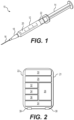
- Fig. 1 shows a perspective view of a medication injection device in the form of a syringe 10 designed for ejecting a fluid.
- Syringe 10 may include a barrel 12, a plunger 14, a needle 16, and a hub 18 connecting needle 16 to barrel 12.
- Barrel 12 may be configured to contain a fluid, for example, a medication 20 and syringe 10 may be configured to dispense medication 20 from needle 16 when plunger 14 is depressed.
- a standard syringe usually contains a plunger head at the end of the plunger that seals the top of the barrel and forces the fluid out the needle when the plunger is depressed.
- the plunger head for a standard syringe is usually just a piece of molded rubber.
- syringe 10 shown in Fig. 1 the standard plunger head has been replaced with a smart or intelligent plunger head 22 (e.g., a dosage measurement system) that is configured to measure and register the quantity of medication 20 administered and the time and date of administration.
- Plunger head 22 may be installed in a standard syringe by withdrawing plunger 14 and removing the standard plunger head and installing smart plunger head 22.
- syringe 10 may be manufactured and supplied with a smart plunger head 22 preinstalled.
- Smart plunger head 22 may be referred herein as either smart plunger head 22 or plunger head 22.
- Plunger head 22 may be sized to correspond with the size of barrel 12.
- plunger head 22 may be formed to fit any size syringe.
- plunger head 22 may be sized to fit a 1 ml, 2 ml, 3 ml, 5 ml, 10 ml, 20 ml, 30 ml, or 50 ml syringe.
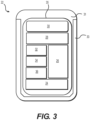
- Fig. 2 shows a schematic of plunger head 22, according to an exemplary embodiment.
- Plunger head 22 may include a transducer 24, a controller 26, a power source 28, and an antenna (e.g., for near field communication (NFC) or a transceiver 30 (e.g., for BLUETOOTH low energy (BLE) communication).
- plunger head 22 may also include a temperature sensor 36. Temperature sensor 36 may be configured to measure the ambient temperature, which may be generally representative of a temperature of plunger head 22 and/or medication 20.
- Transducer 24 may be an ultrasonic transducer configured to send and receive ultrasonic signals. Controller 26 may be programmed with instructions to control the overall operation of the plunger head. Transceiver 30 may be configured to wirelessly communicate with a remote device (e.g., a smart phone, a glucose monitor, an insulin pump, or a computer) using one or more wireless communication methods. The one or more wireless communication methods may include, for example, radio data transmission, Bluetooth, BLE, near field communication (NFC), infrared data transmission, electromagnetic induction transmission, and/or other suitable electromagnetic, acoustic, or optical transmission methods. Power source 28 may be configured to power transducer 24, controller 26, transceiver 30, temperature sensor 36, and other electronic components of plunger head 22.
- a remote device e.g., a smart phone, a glucose monitor, an insulin pump, or a computer
- the one or more wireless communication methods may include, for example, radio data transmission, Bluetooth, BLE, near field communication (NFC), infrared data transmission, electromagnetic in
- the components of plunger head 22 may be at least partially encapsulated in an elastomer 21 (e.g., rubber, ethylene propylene (EPM), Nitrile (NBR), ethylene propylene diene (EPDM), polybutadiene, or polisoprene) that is shaped to define plunger head 22.
- an elastomer 21 e.g., rubber, ethylene propylene (EPM), Nitrile (NBR), ethylene propylene diene (EPDM), polybutadiene, or polisoprene
- plunger head 22 may formed of a plurality of components.
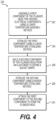
- plunger head 22 may be formed of a first component 31 and a second component 33 that may be fixedly or releasably coupled together such that first component 31 and second component 33 may form plunger head 22, as shown in Fig. 3 .
- First component 31 and second component 33 may each take a variety of shapes.
- Fig. 3 shows a cross-section of one illustrative example where first component 31 may be shaped to define a plug shape while second component 33 may be shaped to define a bucket shape configured to receive the plug shaped first component 31.
- plunger head 22 When installed in barrel 12, plunger head 22 may be oriented such that second component 33 sits below first component 31 such that second component 33 may separate first component 31 from medication 20 contained within barrel 12. As a result, contact with medication 20 within barrel 12 may be limited to second component 33 (i.e., first component 31 may be prevented from contacting medication 20).
- first component 31 and second component 33 may be manufactured from different materials if desired and the available options of materials for first component 31 may be greater because compatibility with medication 20 may be eliminated as a consideration.
- Second component 33 may be manufactured from elastomers or other materials commonly used to manufacture plunger heads thus reducing or eliminating compatibility concerns, which may reduce and simplify regulatory hurdles and testing.
- First component 31 may be manufactured from the same material as second component 33 or from different materials including those which may not be compatible with medication 20.
- second component may be formed of an elastomer (e.g., butyl rubber) while first component may be formed of another plastic, elastomer, or rubber (e.g., silicone rubber).
- the electronic components may be housed in first component 31 while second component 33 may be a simple elastomer mold or liner designed to separate first component 31 from medication 20. In other words, the electronic components may be isolated from medication 20 within first component 31.
- transducer 24, transceiver 30, controller 26, and power source 28 may be plate cylindrically shaped and arranged in a pancake stack configuration within first component 31.
- the thickness of second component 33 may vary.
- the thickness of second component may be about 0.5 millimeters, about 0.6 millimeters, about 0.7 millimeters, about 0.8 millimeters, about 0.9 millimeters, about 1 millimeter, about 1.1 millimeter, greater than about 1.1 millimeter, or less than about 0.5 millimeters.
- second component 33 may be preinstalled in barrel 12 and supplied with syringe 10 while first component 31 may be supplied separately and configured to get inserted into second component 33 while it sits in barrel 12. This arrangement can facilitate the reuse of first component 31 which may house the electronic components.
- first component 31 may be coupled to plunger 14 in order to facilitate easy removal of first component 31 after use.
- first component 31 may include, among other things, a structural support system 35.
- Structural support system 35 may be designed to prevent unintended deformation of first component 31 so that mechanical tolerances may be maintained with desired ranges.
- structural support system 35 may be designed to protect (e.g., prevent damage) of the electronic components due to compressive forces applied to plunger head 22 by plunger 14 when medication 20 is being injected.
- An upper surface of structural support system 35 may be designed to function as a "push plate" for plunger 14 and may be designed to uniformly distribute the compressive forces applied by plunger 14.
- Structural support system 35 may be, for example, a rigid skeleton, cylinder, container, or frame work that surrounds or encloses one or more of the electronic components.
- Fig. 3 shows structural support system 35 surrounding all the electronic components, it is contemplated that in some embodiments, less than all or a portion of the electronic components may be contained within or surrounded by a boundary of structural support system 35.
- first component 31 may be encapsulated, over-molded, or sealed within a coating (e.g., elastomer, silicone, plastic, or rubber coating).
- one or more of the electronic components may be exposed from first component 31.
- a portion of transducer 24 may be exposed from the bottom of first component 31 so that when first component 31 is inserted within second component 33, it mates flush with second component 33.
- first component 31 may also be designed to facilitate proper positioning and orientation of one or more of the electronic components.
- shape of first component 31 and second component 33 may be such that when first component 31 is inserted into second component 33, transducer 24 may be pointed generally down a center of barrel 12 when installed.
- second component 33 may also be designed to facilitate proper orientation of antenna/transceiver 30 when receiving first component 31.
- Structural support system 35 may be made generally semi-rigid or rigid and may be formed of a variety of different materials, for example, plastic, elastomers, composites, metals, or combinations thereof.
- first component 31 may also be arranged to provide additional functionality including, for example, power source 28 (e.g., battery).
- power source 28 may be positioned such that when no compressive forces are applied to first component 31, then there is no electrical contact between power source 28 and the electronic components, thereby keeping the other electronic components powered down (i.e., conserving power). But when compressive forces are applied to first component 31, power source 28 or one or more of the other electronic components may be moved and brought into electrical contact thereby powering up.
- power source 28 may be positioned within first component 31, such that the compressive force applied by plunger 14 acts as an off/off switch, which initiates (e.g., wakes up or powers up) the electronic components of plunger head 22.
- Separating plunger head 22 into first component 31 (that house the electronic components and second component 33 (that contacts the medication) may provide additional advantages.
- a challenge with monolithic encapsulating or overmolding of electronic components is that the process usually exposes the electronic components to higher temperatures during both the molding step and later sterilization step(s), which may damage the electronic components, in particular, power source 28 (e.g., the battery).
- first component 31 and second component 33 By splitting plunger head 22 into separate components (i.e., first component 31 and second component 33), a lower temperature (e.g., about 60 degrees Celsius or less) series of steps for manufacturing and sterilization can be employed for first component 31, which houses the electronic components, while a higher temperature (e.g., greater than about 60 degrees Celsius) series of steps for manufacturing and sterilization can be employed for second component 33, which contacts medication 20.
- first component 31 and second component 33 may then be attached (e.g., by adhesive, bonding, or friction), or another attachment means to form a completed sealed and sterile plunger head 22.
- first component 31 and second component 33 are described herein with reference to plunger head 22, it is contemplated that this multiple or separate component arrangement may be utilized in other applications where electronic components are being packaged (e.g., encapsulated or over-molded) for applications of use where they are alongside sensitive materials (e.g., liquids, medications, chemicals, etc.).
- sensitive materials e.g., liquids, medications, chemicals, etc.
- Method 200 may include, at step 202, assembling first component 31 of plunger head 22, which houses the electronic components, using a lower temperature assembly method. Method 200 may also include, at step 204, sterilizing first component 31 using a lower temperature sterilization method. Method 200 may also include, at step 206, molding second component 33 of plunger head 22 from an elastomer to define, for example, a bucket shape). Method 200 may also include, at step 208, sterilizing a second component 33 using a higher temperature sterilization method. Method 200 may also include, at step 210, attaching first component 31 to second component 33 to form plunger head 22. First component 31 and second component 33 may then be attached (e.g., by adhesive, bonding, or friction), or another attachment means to form a completed seal and sterile plunger head 22.
- first component 31 and second component 33 may then be attached (e.g., by adhesive, bonding, or friction), or another attachment means to form a completed seal and sterile plunger head 22.
- Transducer 24 may be an actuator, piezoelectric element, or speaker-like voice coil configured to generate and send a pressure wave or ultrasonic signal. Transducer 24 may be sized to be slightly smaller than the inner diameter of barrel 12. As shown in Fig. 5 , transducer 24 may be configured to generate ultrasonic signals 25 (e.g., radiated sound energy waves) and send the ultrasonic signals 25 down barrel 12 toward hub 18 and needle 16. The ultrasonic signals can travel through medication 20 along the length of barrel 12 and bounce or reflect off an end 27 of barrel 12 and travel back through medication 20 to plunger head 22. The reflected ultrasonic signals can be received and detected by transducer 24.
- ultrasonic signals 25 e.g., radiated sound energy waves
- the speed of sound in medication 20 may be a known value and thus a distance D can be calculated very accurately based on the time it takes for a ultrasonic signal to travel down and back from transducer 24. As plunger head 22 is moved down barrel 12 distance D will change and by knowing the diameter of barrel 12 then the volume of medication 20 dispensed may be calculated based on the change in distance D.
- a porous membrane 29 may be placed within barrel 12 at end 27.
- Porous membrane 29 may be designed to allow medication 20 to pass through while providing a surface with good reflective properties for the ultrasonic signals 25 to reflect from. Utilizing porous membrane 29 may improve the accuracy of the reflective wave detection and thereby the distance and volume calculations. It is contemplated that other materials may be used besides a porous membrane. It is also contemplated that the geometry of barrel 12 at end 27 may dictate whether a porous membrane is needed. For example, in some embodiments the geometry of end 27 may be designed to produce the desired reflective properties avoiding the need to porous membrane 29.
- controller 26 may be configured to use the temperature of medication 20 to compensate for variations in the temperature that would affect the speed of sound within the medication, thus improving the accuracy of the distance and volume calculations.
- controller 26 may be attached to a printed circuit board and may include one or more processors, including for example, a central processing unit (CPU).
- the processors may include any suitable type of commercially available processor or may be a custom design.
- Controller 26 may include additional components, for example, non-volatile memory (e.g., a flash memory), volatile memory (e.g., a random access memory (RAM)), and other like components, configured to store information).
- Controller 26 may be a microcontroller that can be dynamically updated or include logic that is implemented in static hardware.
- Controller 26 may be programmed with instructions to control the operation of transducer 24. Controller 26 may be programmed with instructions to calculate data representative of the volume of medication 20 dispensed. For example, in some embodiments, controller 26 may be programmed to detect and record the reflection times of the ultrasonic signals 25. Based on the reflection times, controller 26 may track and produce a time profile of the position of transducer 24 (i.e., plunger head 22). Based on the time profile of the position, controller 26 may be able to identify a first distance D1 or starting position (e.g., before medication 20 is dispensed), which may correspond with barrel 12 being filed and a second distance D2 or ending position (e.g., after medication 20 is dispensed), which may correspond with barrel 12 being empty. Controller 26 may then calculate the change in distance between D1 and D2 and based off of the change in distance may calculate the volume (i.e., amount or quantity) of medication 20 dispensed.
- a first distance D1 or starting position e.g., before medication 20
- medication 20 may include an active medication ingredient and a buffer solution.
- concentration of the active medication ingredient may be known or programmed into controller 26 enabling the specific volume of the active medication ingredient to be calculated.
- the concentration of the active medication ingredient may be stored in the non-volatile memory of controller 26.
- additional information regarding the medication 20 may also be stored, for example, ultrasonic velocity vs. temperature data.
- Transducer 24 and/or controller 26 may be programmed to perform various forms of signal conditioning in order to detect the time of the reflected ultrasonic signals 25.
- the signal conditioning may include, for example, amplification, filters, and envelope detection.
- Transducer 24 and/or controller 26 may use the signal conditioning to determine for example, time to first rising edge or time to maximum reflective value in order to determine the reflection time.
- Plunger head 22 may transmit data (e.g., the amount of medication 20 dispensed and time and date it was dispensed) to a remote device (e.g., a smart phone, a glucose monitor, an insulin pump, or a computer) via one or more of the wireless communication methods.
- a remote device e.g., a smart phone, a glucose monitor, an insulin pump, or a computer
- plunger head 22 may transmit data to a remote device 50, which may be a smart phone.
- Plunger head 22 may have a unique identifier so remote device 50 may be able to identify and process the information received properly.
- Plunger head 22 may transmit this information to remote device 50 immediately or shortly after the medication is administered or plunger head 22 may store the information until the remote device is paired and within range.
- plunger head 22 may wait to initiate transmitting of the information to remote device 50 until initiated by remote device 50.
- remote device 50 may transmit the information to a caregiver (e.g., a doctor) or upload the information to the cloud so it may be saved to the patient's medical history and may be accessed by the caregiver.
- a caregiver e.g., a doctor
- the ability of a caregiver or a patient to access and review the dose history may improve treatment.
- the ability of a caregiver to review a diabetic insulin injection history and continuous glucose measurement data may enable the caregiver to adjust the prescribed treatment to improve the therapeutic effect, for example, by better stabilizing the patient's glucose levels.
- Plunger head 22 and/or remote device 50 may be programmed to automatically differentiate a portion of the volume dispensed as part of an air shot versus the portion of volume injected into a patient.
- plunger head 22 and/or remote device may be programmed to detect and identify an air shot.
- An air shot may also be referred to as a prime shot or safety shot.
- An air shot is a common practice associated with medication injection devices (e.g., insulin pens and syringes) and is often a recommended step.
- An air shot may be defined as priming of the medication injection device by dispensing a small volume (e.g., 2 units) of medication 20 into the air prior to injection.
- Fig. 7 shows an example of a user performing an air shot.
- the primary purposes of an air shot are to remove bubbles from the medication within the medication injection device, fill the needle, and clear any potential debris from the needle (e.g., when a needle is reused). It is usually recommended that one or more air shots should be performed until a steady stream is dispensed from the end of the needle.
- the volume of medication dispensed during the air shot can be subtracted from the total volume of medication 20 dispensed to determine the actual volume of medication 20 injected in a patient.
- the volume of the air shot and the volume of the actual injection may be logged and recorded so a caregiver may monitor if recommended procedures (e.g., an air shot) are actually being followed and the frequency at which they are being followed.
- An algorithm processing and analyzing the data collected, stored, and/or transmitted by plunger head 22 may be programmed to determine or identify an air shot based on one or more recognizable events (e.g., air shot events) that may be indicative of an air shot.
- the algorithm may run locally on plunger head 22 (e.g., using controller 26).
- the algorithm may run on remote device 50.
- the algorithm may run elsewhere (e.g., in the cloud, remote server, or the like) and the data may be uploaded by remote device 50.
- the algorithm may be programmed to identify an air shot based on one or more air shot events where the probability of accurate identification increases based on the number of air shot events utilized in combination.
- a variety of different air shot events may be detected and/or recognized and utilized by the algorithm as described below.
- one air shot event the algorithm may use to identify an air shot may be an air shot volume event.
- An air shot volume event may be when a volume of medication is dispensed (e.g., 2 units) that is indicative of an air shot (e.g., air shot volume). For example, if two fluid dispensing events occur in a series, a controller may determine that the first fluid dispensing event is the air shot event if the first quantity of the fluid dispensed is smaller than the second quantity of the fluid dispensed.
- an air shot volume event may be identified by controller 26 using the reflection times of the ultrasonic signals 25.
- controller 26 may identify this as an air shot volume event.
- manufacturers of medical injection devices standardize their injection procedures based on industry norms and commonly the procedures instruct the patients to perform a 2-unit air shot before each injection. It is contemplated that the volume programmed to be indicative of an air shot may be adjusted if industry norms changes or other volumes of air shot may be utilized.
- the algorithm may utilize a volume range that may extend above or below 2 units (e.g., plus or minus 5%, 10%, 20%, 25%, or more) in order compensate for potential inaccuracy in a patient's operation or inaccuracy in a medication injection device.
- Another air shot event the algorithm/controller may use to identify and air shot may be when a pattern of activity (e.g., a sequence of dispensed volumes) is indicative of an air shot.
- This type of air shot event may be referred to herein as an air shot pattern event.
- a pattern of activity e.g., a sequence of dispensed volumes
- This type of air shot event may be referred to herein as an air shot pattern event.
- a pattern event e.g., a sequence of dispensed volumes
- This type of air shot event may be referred to herein as an air shot pattern event.
- an air shot pattern event For example, often there may be long periods of inactivity (i.e., no dispensing) followed by a dispensing of a small dose (e.g., 2 units), quickly followed by dispensing of another dose, and then another long period of inactivity.
- the long period of inactivity typically corresponds to the time in between injections.
- the algorithm may be programmed to detect when there is a long (or threshold) period of inactivity (e.g., 5 min, 10 min, or more), a small dispensing of fluid, a short gap (e.g., about 5 seconds, about 4 seconds, about 3 seconds, about 2 seconds), and a second volume of medication being dispensed.
- the algorithm may identify the first volume as an air shot and the second volume as an injection.
- a first volume of medication dispensed after a period of inactivity may be recognized as an air shot.
- This air shot event may be referred to herein as an air shot pattern event.
- the algorithm may be programmed to recognize the first two volumes as air shot, which may be the case if a second air shot was needed to achieve a steady unimpeded stream from the needle.
- transducer 24 may be configured to operate as a piezoelectric element, which can output a pressure signal to controller 26 indicative of the present pressure within barrel 12. In this embodiment transducer 24 is acting as a dosage tracking system. Thus, data representative of pressure over time may be collected by controller 26 when a volume is dispensed from barrel 12. The pressure over time data may be used to calculate a rate of pressure change.
- controller 26 may be programmed to identify a dispensing event as an air shot pressure event if the rate of pressure change is above a pressure change threshold, or if a first rate of pressure change is greater than a second rate of pressure change in a series of dispensing events.
- Another air shot event the algorithm may use to identify an air shot may be when plunger head 22 moves at a velocity indicative of an air shot.
- This type of air shot event may be referred to herein as an air shot velocity event.
- controller 26 may be programmed to identify a dispensing event as an air shot velocity event if the velocity during the dispensing event is above a velocity threshold, or if the velocity of dispensing first dispensing event in a series of dispensing events is greater than a second dispensing events.
- the velocity may be indirectly measured with a dosage tracking system (in this embodiment the transducer measuring the position) and output to the controller.
- the algorithm may also be programmed to incorporate and recognize an air shot based on the orientation or the movement of the medical injection device or plunger head 22.
- plunger head 22 may include an accelerometer (or other orientation tracker) that controller 26 may utilize to determine and track orientation or movement of plunger head 22 and syringe 10.
- the accelerometer output may be used to identify when the syringe 10 is positioned in a generally vertical orientation (e.g., dispensing end of the medication injection device is pointing upwards), as shown in Fig. 7 , which is commonly the orientation when performing an air shot because it facilitates the bubbles moving to the top and getting removed.
- the orientation tracker may calculate an orientation of the medication injection device, and output an indication of the orientation in the data sent to the controller. This type of air shot event may be referred to herein as an air shot orientation event.
- the rolling of the syringe back and forth will likely result in a unique easily identifiable series of outputs from the accelerometer, which the algorithm may utilize to recognize that it is likely that an air shot will be performed shortly after this event within a threshold period of time.
- This type of air shot event may be referred to herein as an air shot mixing event.
- the first fluid dispensing event after a bubble dislodge event e.g., the characteristic acceleration of tapping/striking the medication injection device
- a mixing event e.g., the characteristic acceleration of rolling the syringe
- the algorithm may be programmed to recognize an air shot based on a single air shot event.
- the algorithm may be programmed to identify an air shot based an air shot volume.
- utilizing just a single type of air shot event e.g., based on volume alone
- the algorithm may be programmed to identify a 2-unit dispensed volume (i.e., an air shot volume event) as an air shot it may misidentify a 2-unit injection as an air shot.
- the other types of air shot events may be utilized in isolation to identify an air shot and in some cases may provide more reliable accuracy.
- the algorithm may be programmed to recognize an air shot based an air shot pattern event, air shot pressure event, air shot velocity event, air shot orientation event, air shot bubble dislodge event, or air shot mixing event.
- the algorithm may utilize two or more type of the air shot events described herein to recognize an air shot.
- the algorithm utilizes multiple events to recognize an air shot it can limit or prevent misidentification of an air shot or failure to identify an air shot.
- the more events the algorithm utilizes and detects may increase the probability of accurate air shot detection.
- the algorithm may utilize any number and combination of the events described herein.
- the algorithm may be programmed to utilize an air shot pattern event in combination with an air shot volume event.
- the algorithm may also incorporate in an air shot pressure event and/or an air shot velocity event to further increase the probability of accurate air shot identification.
- plunger head 22 that does not include an optional accelerometer.
- an embodiment of plunger head 22 having an accelerometer may utilize these combinations of events in addition to an air shot orientation event, air shot bubble dislodge event, and an air shot mixing event.
- the algorithm may be programmed to calculate and record an accuracy probability of each recognized air shot based on the number of events and which events were utilized in the determination.
- the algorithm may adjust over time which type of events it uses to identify an air shot based on a patient's prior injection routine or behavior. In other words, the algorithm may evaluate prior injection behavior and based on that prior behavior may select the air shot events that will produce the highest likelihood of accurate air shot identification.
- the algorithm may be programmed to identify an air shot when, for example, two, three, or more of the events are all detected.
- the algorithm may be programmed to identify an air shot when at least a portion of the events are detected.
- the algorithm may be programmed to identify an air shot when two or more out of the total number of events the algorithm is utilizing are detected. Which two or more are detected may vary from air shot to air shot.
- the algorithm may be programmed to always require the detection of at one of the events before identifying an air shot.
- plunger head 22 may also include a crystal oscillator 32 configured to keep a real time clock (RTC) so that the date and time of each injection may be accurately recorded and stored in memory of controller 26.
- Crystal oscillator may be, for example, a 32 KHZ crystal oscillator.
- controller 26 may include an internal oscillator (e.g., RC oscillator), which may be calibrated using crystal oscillator 32.
- the internal RC oscillator may be, for example, a 10 MHZ RC oscillator.
- Internal RC oscillator may provide sufficient time accuracy to measure the position (e.g., distance D) of plunger head 22 to within, for example, about 150 microns.
- transducer 24 may be used as an oscillator or as a calibrator for the internal RC oscillator.
- the frequency of the RC oscillator may be up-converted on controller 26 to a higher frequency.
- the RC oscillator may be used to drive a higher-frequency phase-locked loop.
- plunger head 22 may be designed to back-interpolate the time of each injection enabling crystal oscillator 32 to be eliminated.
- crystal oscillator 32 may consume a significant amount of power, thus eliminating the crystal oscillator 32 can save a significant amount of power as well as save space.
- Plunger head 22 may back-interpolate the time of each injection by relying on the real time clock of the remote device.
- the method of back-interpolating may start with plunger head 22 taking and logging a series of data samples (e.g., plunger head 22 positions).
- Plunger head 22 may be programmed to take and log the data samples at an approximately regular interval.
- the data samples may be stored, for example in a memory of controller 26 in the order measured.
- the data samples may be logged and stored into memory with other data values (e.g., calculated injection volume, temperature, etc.).
- the collection of logged data samples may be transferred / transmitted (e.g., uploaded) to a remote device, which will receive the data samples in the same order.
- the remote device may rely on the approximately regular interval of the data sample logging to back-interpolate from the actual time at time of transfer, as determined by the RTC of the remote device. By back-interpolating the approximate time of each data sample logged may be determined. For example, if there were six samples transferred to the remote device and they were known to have been captured at about 60 minute intervals then the remote device may determine the time of each of the six samples were logged working backwards from the time of data transfer. However, this example produces about a 60 minute uncertainty in the calculated time of the data sample points because the time of transfer may not be synchronized with the time of data sample logging. However, plunger head 22 may be programmed to log data samples at a faster frequency to reduce the uncertainty or increase the accuracy. For example, data samples may be logged every 30 minutes, 15 minutes, 10 minutes, 5 minutes, 1 minute, or less than 1 minute.
- the approximately regular interval may be determined or maintained by a less accurate, less power consuming, smaller timing device (e.g., an oscillator). It is noted that the reduce accuracy of the timing device may result in the approximately regular interval drifting due to a variety of factors, for example, temperature, voltage, or factory-determined offsets.
- plunger head 22 may store the factory determined offsets and be programmed with instructions to measure and log the temperature and/or voltage.
- Controller 26 may be programmed with instructions to use the factory determined offsets and the logged temperatures and voltages to generate a model to correct drift (i.e., change in interval) between the approximately regular intervals caused by variability in the temperature and the voltage. This same method may also be used in other embodiments to correct drift even in a more accurate time tracking system (e.g., a quartz referenced system).
- Antenna or transceiver 30 may be used to communicate with a variety of remote devices (e.g., smart phones, glucose monitors, insulin pumps, computers, etc.).
- Plunger head 22 may transmit the information via any suitable wireless communication method.
- plunger head 22 may utilize radio data transmission, BLUETOOTH or BLUETOOTH LOW ENERGY (BLE), near field communication (NFC), infrared data transmission or other suitable method.
- information may also be wirelessly transmitted from a remote device to plunger head 22 via antenna 30.
- the date and time may be set by writing to controller 26 via the wireless communication.
- plunger head 22 may also include a force sensor 34.
- Force sensor 34 may be configured to detect when a force is applied to plunger head 22 via plunger 14.
- Force sensor 34 may be, for example, a simple spring-loaded switch that is molded into the plunger head 22.
- transducer 24 may be configured to function as a force sensor thereby eliminating the need for a separate force sensor 34.
- transducer 24 may have a piezoelectric element that may detect the dynamic changes in pressure when a user depresses plunger 14.
- Power source 28 may be any suitable power source.
- power source 28 may be a battery, a capacitor, or the like.
- power source 28 may be rechargeable via wireless energy transmission, for example, inductive coupling, resonant inductive coupling, radio frequency (RF) link, or the like.
- power source 28 may be a non-rechargeable battery that is configured to last the storage and operational life of plunger head 22, for which the combined storage and operational life may be about 1 year, about 2 years, about 3 years, or more.
- power source 28 may be a watch battery.
- power source 28 may be eliminated.
- plunger head 22 may be designed to enter a low-power sleep mode while in storage. Plunger head 22 may be programmed to enter low-power sleep mode as part of the manufacturing and testing process for plunger head 22 or the medication injection device. When in low-power sleep mode the rate of power consumption may be a fraction of the rate of power consumption for normal operation. While in low-power sleep mode, controller 26 may be programmed with instructions to periodically wake up to measure the temperature. Controller 26 may also log the temperature to create a temperature history. Alternatively, in some embodiments controller 26 may be programmed to log the temperature only when there is a change in temperature, thus saving on data storage. The efficacy of some medications is affected by temperature. For example, insulin is sensitive to hot and cold temperatures.
- Plunger head 22 thus may monitor the temperature medication 20 through storage and up through use to ensure it stays within an acceptable range. If the temperature of the medication 20 goes outside the acceptable range then plunger head 22 may be configured to send an alert.
- the type of alert may vary.
- plunger head 22 may include a display (not shown in Fig. 2 ) and the alert may be a flashing light or a visual indicator.
- plunger head 22 may include a speaker and the alert may be auditory, for example, a beeping sound.
- the alert may be transmitted to a remote device and the remote device may display a visual alert and/or play an auditory alert.
- plunger head 22 may also be designed to utilize the temperature measurement to transition between modes.
- a medication injection device that includes plunger head 22 and medication 20 may often be stored at a lower temperature (e.g., below a normal room temperature of about 20 to about 22 degrees Celsius). Subsequently, prior to use, often the temperature will be the medication device, including plunger head 22 and in particular medication 20 will be raised to room temperature because injection of cold fluids can be painful. Thus, usually there will be a transition from a lower temperature to a higher temperature shortly before use thereby triggering a change in the mode of plunger head 22.
- controller 26 may be programmed to detect the temperature change that is expect prior to use and when detected controller 26 may be programmed to transition plunger head 22 from low-power sleep mode into an initialization mode. Controller 26 may be programmed to pair with a remote device while in the initialization mode. After a successful pairing, controller 26 may be programmed to transition plunger head 22 to an operational mode and start sending and receiving ultrasonic waves and measuring the position of transducer 24. In some embodiments, controller 26 may be programmed to reenter the low-power sleep mode if it is unable pair with a remote device within a certain period of time (e.g., if no remote device is present).
- Controller 26 may also be programmed to reenter the low-power sleep mode after a period of inactivity (e.g., no measurable change in transducer 24 position after a programmed period of time). Controller 26 may also be programmed to reenter the low-power sleep mode if a subsequent temperature change (e.g., a decrease in temperature from normal room temperature) is detected. Controller 26 may be programmed to transition directly from the low-power sleep mode back to the operational mode if a successful pairing with a remote device has already occurred.
- a period of inactivity e.g., no measurable change in transducer 24 position after a programmed period of time
- Controller 26 may also be programmed to reenter the low-power sleep mode if a subsequent temperature change (e.g., a decrease in temperature from normal room temperature) is detected. Controller 26 may be programmed to transition directly from the low-power sleep mode back to the operational mode if a successful pairing with a remote device has already occurred.
- plunger head 22 may also be configured to detect air bubbles in medication 20. Air bubbles if injected can be deadly so detection of air bubbles is advantageous.
- transducer 24 of plunger head 22 may be configured to detect small ultrasonic echoes created by the reflection of the ultrasonic waves off the air bubbles in addition to the main echo caused by the end of barrel 12.
- Plunger head 22 may be configured to transmit an alert if air bubbles are detected. The alert may be communicated in the same ways as the temperature alert described above.
- plunger head 22 may also be configured to differentiate, verify, and/or identify medication 20 contained in syringe 10. For example, when barrel 12 is loaded with medication 20, plunger 14 and plunger head 22 may be pulled all the way back to its stopping point and the distance from plunger head 22 to end 27 of barrel 12 may be known enabling controller 26 to solve for the speed of sound of the fluid, which depends on temperature and density. The temperature may be measured by temperature sensor 36 so the density may be determined and based on the density the amount of solids dissolved in the fluid may also be determined. In addition, the viscosity of the medication 20 may be measured based on the amplitude of the reflected ultrasonic signals 25 because more viscous fluids dissipate more energy.
- plunger head 22 may also include electrodes 38 connected to controller 26 configured to measure the conductivity of medication 20.
- the electrodes 38 may protrude out from the surface of plunger head 22 into barrel 12 where the electrodes 38 may contact medication 20. With the density, conductivity, and viscosity of medication 20 determined, controller 26 may have a sufficient number of properties to profile medication 20.
- the profiling may be configured to differentiate medication 20 in order to determine if it from a prescribed class of medication. In some embodiments, the profiling may be configured to verify that medication 20 is the same as the medication that is prescribed for the patient. In some embodiments, the profiling may be configured to identify the medication 20.
- plunger head 22 as described herein may be combined with a syringe that has been modified to include a piezo linear motor.
- the piezo linear motor may be incorporated into the wall of the barrel of the syringe and a piezo element may be incorporated into plunger head 22.
- the piezo linear motor may be configured to drive or "walk" the plunger head 22 down the barrel of the syringe by driving the piezo element, thereby forcing the medication from the syringe.
- This embodiment may enable the piezo linear motor to control medication dispensing while plunger head 22 may simultaneously track the amount of medication being dispensed.
- plunger head 22 may control the piezo linear motor or plunger head 22 can communication with a remote device that can control the piezo linear motor such that it dispenses a set amount of medication.
- Fig. 8 shows a smart syringe system 40, according to another exemplary embodiment.
- System 40 may be designed for use with a standard disposable syringe 10 or other medication injection devices. Similar to plunger head 22, smart syringe system 40 may be configured to measure and register the quantity of medication 20 administered and the date and time of administration.
- Smart syringe system 40 may include a smart or intelligent plunger head 42, similar to plunger head 22, and a cuff 44.
- plunger head 42 may be designed to be disposable after a single use while cuff 44 is reusable.
- Embodiments of plunger head 42 designed to be disposable after a single use may houses only the minimum number of components to carry out its function while any optional or ancillary components may be housed in cuff 44 to minimize manufacturing cost of plunger head 42.
- the manufacturing cost of plunger head 42 may also be minimized by using lower cost components (e.g., transducers, antennas, and controllers) and materials (e.g., rubbers, polymers, plastics) that are less robust and durable, and instead may be designed for shorter operational life spans.
- Plunger head 42 may be designed to be supplied with or installed into a disposable syringe 10 and after administering a dose of medication 20, syringe 10 along with plunger head 42 may be disposed of or recycled.
- cuff 44 may be designed to be reused numerous times. For example, a disposable syringe 10 may be inserted through cuff 44 and after medication 20 is administered; cuff 44 may be removed from the used syringe 10 and be saved for later use.
- both plunger head 42 and cuff 44 may be reusable. For example, after medication 20 is administered by syringe 10, both plunger head 42 and cuff 44 may be removed and saved for later use.
- Plunger head 42 and cuff 44 can come in different sizes so they may be used with any size syringe.
- plunger head 42 may be sized to fit within the barrel 12 of any size syringe 10 while cuff 44 may be configured to have a passage 46 configured to receive any size barrel 12 of syringe 10.
- Plunger head 42 and cuff 44 may be configured to have some or all of the same components (e.g., a transducer 24, a controller 26, a power source 28, an antenna 30, crystal oscillator 32, force sensor 34, and a temperature sensor 36) as plunger head 22 and perform at least all the same operations as plunger head 22.
- Some of the components may be housed in plunger head 42 while some of the components may be housed in cuff 44.
- plunger head 42 may be designed to house the minimum number of components to carry out its functions.
- system 40 may be configured such that all the components that can be housed in cuff 44 are, rather than plunger head 42.
- such components may include a form of memory for data storage.
- plunger head 42 may include the transducer 24, antenna 30, and a controller 26 while cuff 44 may also include a separate controller, a power source, and a separate antenna.
- plunger head 42 may be passive (e.g., battery-free) and configured to be controlled and powered by cuff 44 via wireless energy transmission.
- Cuff 44 may also be configured to communicate with a remote device (e.g., a smart phone, a glucose sensor, an insulin pump, or a computer) thereby enabling the volume of medication and the time and date of administering to be uploaded to another device or the cloud.
- a remote device e.g., a smart phone, a glucose sensor, an insulin pump, or a computer
- cuff 44 may include a display.
- Cuff 44 may be configured to display any alerts (e.g., high temperature or improper medication) to the user.
- Cuff 44 may also display the volume, date, and time after medication has been dispensed.
- the display may also be configured to allow user input (e.g., touch screen). For example, the user may program in the date, the time, the type of medication or other information.
- Plunger head 22 and system 40 described herein may be utilized for a variety of methods for tracking administering of a medication to a patient delivered by syringe.
- Various methods of utilizing plunger head 22 and system 40 will now be explained with reference to Fig. 9 .
- the methods as described herein may be performed by a caregiver (e.g., a doctor or nurse) in a hospital or other inpatient setting.
- the methods as described herein may be performed by a caregiver (e.g., a doctor, nurse, or parent) at home or outside a hospital.
- the methods as described herein may be performed by the patient. It is contemplated that the methods described herein may be performed in other settings by other individuals.
- Plunger head 22 may be utilized for a method 100 of tracking administering of a medication to a patient delivered by a medication injection device (e.g., a syringe), according to an exemplary embodiment.
- method 100 may begin by installing plunger head 22 into barrel 12 of syringe 10 (e.g., a disposable syringe).
- syringe 10 may be supplied with plunger head 22 already installed.
- plunger head 22 may be installed as part of the original manufacturing process, which may also include loading of medication 20 (e.g., insulin).
- the barrel 12 of the syringe may be filled with the medication 20.
- This step may be eliminated for embodiments were the medication 20 comes prefilled.
- the barrel 12 may be completely filled or only partially with medication 20.
- the syringe may then be positioned for delivery.
- the needle may be inserted into the skin of the patient or into a drug delivery port connected to the patient.
- the plunger 14 of the syringe 10 may be depressed, which forces plunger head 22 down the barrel 12 and forces the medication 20 out the needle 16.
- method 100 may also include performing an air shot.
- the initial position of plunger head 22 may be known by plunger head 22.
- syringe 10 may be full and plunger head 22 may know the distance between plunger head 22 and end 27 when filled.
- the previous position of plunger head 22 may be known from the last measurement stored.
- the initial position of plunger head 22 may be measured using plunger head 22 prior to any medication 20 being delivered, as described below.
- plunger head 22 may send and receive ultrasonic signals 25 via transducer 24, at step 108.
- Plunger head 22 may send and receive ultrasonic signals 25 the duration of the time the plunger is being depressed.
- Plunger head 22 may measure a time it takes for each of the ultrasonic signals to travel through the medication to an end of the barrel and return to the transducer, at step 110.
- at least a portion of the ultrasonic signals 25 may be sent and received before any medication 20 is dispensed enabling the initial position of plunger head 22 and initial volume of medication 20 to be calculated.
- plunger head 22 may calculate the position of plunger head 22 and a distance plunger head 22 travels over the course of dispensing medication 20.
- the quantity of medication 20 dispensed may be calculated based on the calculated distance plunger head 22 traveled.
- method 100 may include automatically identifying an air shot, as described herein. If an air shot is identified then the volume medication dispensed as part of the air shot may be subtracted from the total volume dispensed in order to determine the actual volume of medication 20 injected.
- an algorithm may be utilized that analyzes the data collected to recognize one or more events indicative of an air shot.
- the calculation of the quantity of medication dispensed may be performed by remote device 50 (e.g., a smart phone, a glucose sensor, an insulin pump, or a computer).
- method 100 may also include transmitting the quantity of the medication dispensed and the time and date the quantity was dispensed to a remote device.
- method 100 may also include uploading the quantity of the medication dispensed and the time and date the quantity was dispensed to the cloud.
- method 100 may also include sending the quantity of the medication dispensed and the time and date the quantity was dispensed to a caregiver.
- method 100 may also include logging a plurality of data samples (e.g., position of plunger head 22) at an approximately regular interval and then back-interpolating the time corresponding to each data sample logged to determine the approximate time the quantity of medication 20 was disposed using the RTC maintained by the remote device as a reference time.
- a plurality of data samples e.g., position of plunger head 22
- method 100 is described with reference to plunger head 22, it may also be performed by system 40, as described herein.
- Fig. 10 is an illustration of an injection pen system 1000 to detect air shots, according to an exemplary embodiment.
- Pen system 1000 includes drug cartridge 1001, injection pen 1007, and processing device 1019 (e.g. , a smart phone). Similar to the embodiments described above, before an injection, pen system 1000 may perform an air shot.
- Drug cartridge 1001 includes cartridge body 1003 (i.e. , a "barrel"), and plunger head 1005.
- plunger head 1005 starts near the rear of drug cartridge 1001 and is pushed forward in drug cartridge 1001 (with a plunger in pen 1007) to expel medication/fluid from the narrow end of drug cartridge 1001.
- Plunger head 1005 may come preinstalled in drug cartridge 1001, or may be swapped in by a user.
- plunger head 1005 may include any of the electronics described above to send and receive ultrasonic signals, measure pressure, measure velocity, etc.
- Injection pen 1007 is a hand-held device and includes needle 1011, chamber 1013 (to hold drug cartridge 1001), body 1015 (including a drug dispensing actuator-"plunger”-to push in plunger head 1005 and extract fluid from drug cartridge 1001), and a drug delivery control switch 1017 (twist the switch to "click” control the dosage).
- injection pen 1007 can take other configurations and have other components.
- a dosage measurement system is disposed within pen 1007, to measure one or more of the quantity of fluid dispensed, pressure in cartridge 1001, number of injection events, fluid velocity during an injection, etc.
- the dosage measurement system may include an accelerometer to measure the orientation of injection pen 1007, and if a user has tapped/rolled the pen to remove bubbles.
- the dosage measurement system in injection pen body 1015 may also include mechanical devices to measure the movement of the plunger (e.g. , an encoder or pawl/cogwheel) in injection pen body 1015 in order to determine a volume of fluid dispensed.
- Injection pen body 1015 may include any of the hardware and logic described above in connection with the syringe embodiments, in accordance with the teachings of the present disclosure. These components may be disposed anywhere in injection pen 1000.
- Processing device 1019 may be coupled to receive data from injection pen 1007 or drug cartridge 1001 to further store/analyze the data.
- Processing device 1019 may receive the data through any wireless transmission method such as Bluetooth, RFID or the like.
- processing device 1019 is a smartphone, and the smartphone has an application running recording how much insulin has been spent from injection pen 1007. Moreover the application is plotting how much insulin has been injected by the user over the past week.
- a tangible machine-readable storage medium includes any mechanism that provides (i . e ., stores) information in a non-transitory form accessible by a machine (e.g. , a computer, network device, personal digital assistant, manufacturing tool, any device with a set of one or more processors, etc.).
- a machine-readable storage medium includes recordable/non-recordable media (e.g. , read only memory (ROM), random access memory (RAM), magnetic disk storage media, optical storage media, flash memory devices, etc.).
Landscapes
- Health & Medical Sciences (AREA)
- Heart & Thoracic Surgery (AREA)
- Vascular Medicine (AREA)
- Engineering & Computer Science (AREA)
- Anesthesiology (AREA)
- Biomedical Technology (AREA)
- Hematology (AREA)
- Life Sciences & Earth Sciences (AREA)
- Animal Behavior & Ethology (AREA)
- General Health & Medical Sciences (AREA)
- Public Health (AREA)
- Veterinary Medicine (AREA)
- Emergency Medicine (AREA)
- Infusion, Injection, And Reservoir Apparatuses (AREA)
Claims (14)
- Dispositif d'injection de médicament (10), comprenant :un cylindre (12) ;un piston (14) disposé pour distribuer un fluide (20) à partir du cylindre ;un système de suivi de dosage couplé pour délivrer en sortie des données indicatives d'une quantité du fluide distribuée ; etun dispositif de commande (26) disposé à l'intérieur du dispositif d'injection de médicament et couplé pour recevoir les données provenant du système de suivi de dosage, dans lequel le dispositif de commande inclut une logique qui, lorsqu'elle est exécutée par le dispositif de commande, amène le dispositif de commande à effectuer des opérations incluant :
déterminer, sur la base des données, si un événement de coup d'air s'est produit pendant la distribution du fluide ; etcaractérisé en ce que le système de suivi de dosage inclut un transducteur ultrasonore (24) situé dans une tête de piston (22) du dispositif d'injection de médicament, le transducteur ultrasonore (24) étant orienté pour émettre des signaux ultrasonores (25) à travers le fluide le long d'une longueur du cylindre et pour recevoir des signaux ultrasonores réfléchis, dans lequel les données sont indicatives d'un temps de vol des signaux ultrasonores ; et dans lequel la détermination comprend les étapes consistant à :mesurer une distance parcourue par la tête de piston en fonction du temps de vol des signaux ultrasonores ; etdéterminer que l'événement de coup d'air s'est produit lors de la distribution du fluide lorsque la distance parcourue par la tête de piston est inférieure à une distance de seuil. - Dispositif d'injection de médicament selon la revendication 1, dans lequel l'événement de coup d'air inclut un événement de distribution de fluide où le fluide est réputé ne pas avoir été injecté dans un corps.
- Dispositif d'injection de médicament selon la revendication 1, dans lequel le système de suivi de dosage inclut un dispositif de suivi d'orientation pour calculer une orientation du dispositif d'injection de médicament et pour délivrer en sortie une indication de l'orientation dans les données, et dans lequel la détermination, sur la base des données, que l'événement de coup d'air s'est produit ou non lors de la distribution du fluide comprend l'étape consistant à :
déterminer que l'événement de coup d'air s'est produit lorsqu'une extrémité de distribution du dispositif d'injection de médicament est dirigée vers le haut pendant la distribution du fluide. - Dispositif d'injection de médicament selon la revendication 1, dans lequel la détermination, sur la base des données, que l'événement de coup d'air s'est produit ou non pendant la distribution du fluide comprend les étapes consistant à :mesurer des quantités du fluide distribué au cours d'une séquence d'événements de distribution de fluide incluant un premier événement de distribution de fluide se produisant avant un second événement de distribution de fluide ;comparer une première quantité du premier événement de distribution de fluide à une seconde quantité du second événement de distribution de fluide ; etdéterminer que le premier événement de distribution de fluide est l'événement de coup d'air lorsque la première quantité du fluide est inférieure à la seconde quantité du fluide.
- Dispositif d'injection de médicament selon la revendication 1, dans lequel la détermination, sur la base des données, que l'événement de coup d'air s'est produit ou non pendant la distribution du fluide comprend les étapes consistant à :détecter une période d'inactivité de seuil du dispositif d'injection de médicament ;détecter une séquence d'événements de distribution de fluide à la suite de la période d'inactivité de seuil ; etdéterminer qu'un premier de la séquence d'événements de distribution de fluide immédiatement après la période d'inactivité de seuil est l'événement de coup d'air.
- Dispositif d'injection de médicament selon la revendication 1, dans lequel le système de suivi de dosage est couplé pour détecter une pression à l'intérieur du cylindre et les données sont indicatives de la pression, dans lequel la détermination, sur la base des données, que l'événement de coup d'air s'est produit ou non pendant la distribution du fluide comprend les étapes consistant à :mesurer des taux de changement de la pression à l'intérieur du cylindre pendant une séquence d'événements de distribution de fluide incluant un premier événement de distribution de fluide se produisant avant un second événement de distribution de fluide ;comparer un premier taux de changement de pression pendant le premier événement de distribution de fluide à un second taux de changement de pression pendant le second événement de distribution de fluide ; etdéterminer que le premier événement de distribution de fluide est l'événement de coup d'air lorsque le premier taux de changement de pression est supérieur au second taux de changement de pression.
- Dispositif d'injection de médicament selon la revendication 1, dans lequel le système de suivi de dosage inclut un accéléromètre couplé pour mesurer un mouvement du dispositif d'injection de médicament et délivre en sortie une indication du mouvement dans les données, et dans lequel le dispositif de commande inclut en outre une logique qui, lorsqu'elle est exécutée par le dispositif de commande, amène le dispositif de commande à effectuer des opérations incluant :identifier un mouvement de tapotement du dispositif d'injection de médicament comme un événement de délogement de bulle ; etdéterminer qu'un événement de distribution de fluide suivant l'événement de délogement de bulle dans une première période de temps de seuil est l'événement de coup d'air.
- Dispositif d'injection de médicament selon la revendication 1, dans lequel le dispositif de commande inclut en outre une logique qui, lorsqu'elle est exécutée par le dispositif de commande, amène le dispositif de commande à effectuer des opérations supplémentaires, incluant :identifier un mouvement de roulement du dispositif d'injection de médicament comme un événement de mélange de fluide ; etdéterminer qu'un événement de distribution de fluide suivant l'événement de mélange de fluide dans une seconde période de temps de seuil est l'événement de coup d'air.
- Dispositif d'injection de médicament selon la revendication 1, dans lequel le dispositif d'injection de médicament inclut au moins un parmi un stylo à insuline ou une seringue.
- Procédé de détection d'un coup d'air à partir d'un dispositif d'injection de médicament selon l'une quelconque des revendications 1 à 9, le procédé comprenant les étapes consistant à déterminer, sur la base des données, si un événement de coup d'air s'est produit ou non pendant que le dispositif d'injection de médicament distribue le fluide, par l'intermédiaire des étapes consistant à :mesurer une distance parcourue par la tête de piston en fonction du temps de vol des signaux ultrasonores ; etdéterminer que l'événement de coup d'air s'est produit lors de la distribution du fluide lorsque la distance parcourue par la tête de piston est inférieure à une distance de seuil.
- Procédé selon la revendication 10, comprenant en outre les étapes consistant à :envoyer les signaux ultrasonores avec le transducteur du système de suivi de dosage à travers le fluide le long de la longueur du cylindre du dispositif d'injection de médicament ;recevoir les signaux ultrasonores réfléchis avec le transducteur, dans lequel les données en sortie à partir du système de suivi de dosage indiquent un temps de vol entre l'émission et la réception des signaux ultrasonores ; etcalculer un volume de fluide distribué pendant chacun de multiples événements de distribution de fluide en fonction de la durée de vol des signaux ultrasonores ; etdéterminer que l'événement de coup d'air s'est produit pendant un ou plusieurs des événements de distribution de fluide sur la base du volume de fluide distribué pendant chacun des événements de distribution de fluide qui est inférieur à un volume de seuil.
- Procédé selon la revendication 10, comprenant en outre les étapes consistant à :mesurer des vitesses d'événements de distribution de fluide à l'aide du système de suivi de dosage pendant une séquence d'événements de distribution de fluide incluant un premier événement de distribution de fluide se produisant avant un second événement de distribution de fluide ;comparer une première vitesse pendant le premier événement de distribution de fluide à une seconde vitesse pendant le second événement de distribution de fluide ; etdéterminer que le premier événement de distribution de fluide inclut l'événement de coup d'air lorsque la première vitesse est supérieure à la seconde vitesse.
- Procédé selon la revendication 10, comprenant en outre l'étape consistant à :
calculer, sur la base des données reçues au niveau du dispositif de commande, une quantité de médicament distribuée à un patient en soustrayant une quantité du fluide distribué pendant l'événement de coup d'air d'une quantité totale distribuée du fluide. - Support de stockage lisible par machine comprenant des instructions exécutables par machine configurées pour, lorsqu'elles sont exécutées par une machine, amener la machine à exécuter un procédé selon l'une quelconque des revendications 10 à 13.
Applications Claiming Priority (4)
| Application Number | Priority Date | Filing Date | Title |
|---|---|---|---|
| US201662329605P | 2016-04-29 | 2016-04-29 | |
| US201662434662P | 2016-12-15 | 2016-12-15 | |
| US15/498,903 US10688255B2 (en) | 2016-04-29 | 2017-04-27 | Air shot detection |
| PCT/US2017/030068 WO2017189970A1 (fr) | 2016-04-29 | 2017-04-28 | Détection de coup d'air |
Publications (2)
| Publication Number | Publication Date |
|---|---|
| EP3448471A1 EP3448471A1 (fr) | 2019-03-06 |
| EP3448471B1 true EP3448471B1 (fr) | 2024-05-01 |
Family
ID=60157758
Family Applications (1)
| Application Number | Title | Priority Date | Filing Date |
|---|---|---|---|
| EP17722350.0A Active EP3448471B1 (fr) | 2016-04-29 | 2017-04-28 | Détection de coup d'air par capteurs à ultrasons |
Country Status (4)
| Country | Link |
|---|---|
| US (1) | US10688255B2 (fr) |
| EP (1) | EP3448471B1 (fr) |
| CN (1) | CN210750665U (fr) |
| WO (1) | WO2017189970A1 (fr) |
Families Citing this family (22)
| Publication number | Priority date | Publication date | Assignee | Title |
|---|---|---|---|---|
| US10953155B2 (en) | 2016-04-29 | 2021-03-23 | Verily Life Sciences Llc | Pressure sensor in plunger head to wake up electronics |
| AU2017312652A1 (en) | 2016-08-17 | 2019-04-04 | Nisha Sawhney | Injection monitoring device and system |
| US10956538B2 (en) | 2016-12-03 | 2021-03-23 | Verily Life Sciences Llc | Low-power systems and methods for determining measurement times of values obtained by a measuring device |
| JP7204688B2 (ja) | 2017-06-09 | 2023-01-16 | サノフイ | 投与量検知用の電子機器 |
| USD834182S1 (en) * | 2017-06-20 | 2018-11-20 | Genesis Cosmetics LLC | Syringe |
| WO2019096720A1 (fr) * | 2017-11-14 | 2019-05-23 | Sanofi | Intégration d'un capteur à ultrasons dans un élément de butée de piston d'un dispositif d'injection |
| WO2019096726A2 (fr) * | 2017-11-14 | 2019-05-23 | Sanofi | Conservation de puissance dans un dispositif d'injection |
| MX2020005338A (es) | 2017-11-23 | 2020-10-14 | Sanofi Sa | Dispositivo de inyección de medicamento con codificador rotatorio. |
| JP7307097B2 (ja) * | 2018-01-26 | 2023-07-11 | サノフイ | 注射用薬剤の容器 |
| EP3743133A1 (fr) * | 2018-01-26 | 2020-12-02 | Sanofi | Récipient de médicament injectable |
| WO2019149868A1 (fr) * | 2018-02-05 | 2019-08-08 | Sanofi | Ensemble capteur de pression et procédés pour dispositifs d'injection |
| JP7313360B2 (ja) * | 2018-02-12 | 2023-07-24 | サノフイ | ストッパ |
| JP7568662B2 (ja) | 2019-07-01 | 2024-10-16 | サノフイ | 注射デバイスでの電子機器のスリープ解除 |
| EP4022632A1 (fr) * | 2019-08-30 | 2022-07-06 | Eli Lilly and Company | Procédés et appareil pour déterminer une dose de dispositif |
| US20220265934A1 (en) * | 2019-08-30 | 2022-08-25 | Becton, Dickinson And Company | Syringe with disposable body and reusable cap enabling dose capture |
| CN114761056A (zh) * | 2019-11-26 | 2022-07-15 | 赛诺菲(中国)投资有限公司 | 剂量记录装置 |
| MX2022010477A (es) * | 2020-02-25 | 2022-09-19 | Boehringer Ingelheim Int | Dispositivo de inyeccion y una pieza reutilizable del mismo. |
| USD957625S1 (en) | 2020-04-29 | 2022-07-12 | Susan Reynolds | Syringe |
| EP3974012A1 (fr) * | 2020-09-29 | 2022-03-30 | Ypsomed AG | Identification d'événement d'amorçage dans des dispositifs de distribution |
| EP3984575A1 (fr) * | 2020-10-14 | 2022-04-20 | Becton Dickinson France | Indicateur de fin de dose pour dispositif d'injection médical |
| EP4326364A1 (fr) * | 2021-04-23 | 2024-02-28 | Sanofi | Module de codeur électronique et dispositif d'administration de médicament comprenant celui-ci |
| CN113476692A (zh) * | 2021-07-31 | 2021-10-08 | 凯联医疗科技(上海)有限公司 | 一种基于电磁推进和微流量检测控制的输注泵 |
Family Cites Families (26)
| Publication number | Priority date | Publication date | Assignee | Title |
|---|---|---|---|---|
| US5720733A (en) | 1994-07-22 | 1998-02-24 | Raya Systems, Inc. | Apparatus for determining and recording injection doses in syringes using electrical capacitance measurements |
| US6743202B2 (en) | 1998-06-15 | 2004-06-01 | Medrad, Inc. | Encoding of syringe information |
| DE19840992A1 (de) | 1998-09-08 | 2000-03-09 | Disetronic Licensing Ag | Drucküberwachung eines bei einer Infusion oder Injektion dosiert zu verabreichenden Produktfluids |
| US7993108B2 (en) | 2002-10-09 | 2011-08-09 | Abbott Diabetes Care Inc. | Variable volume, shape memory actuated insulin dispensing pump |
| ATE404233T1 (de) | 2004-10-21 | 2008-08-15 | Novo Nordisk As | Injektionsvorrichtung mit mitteln zur meldung der zeit seit der letzten injektion |
| US8066629B2 (en) * | 2005-02-24 | 2011-11-29 | Ethicon Endo-Surgery, Inc. | Apparatus for adjustment and sensing of gastric band pressure |
| JP2009500061A (ja) | 2005-06-29 | 2009-01-08 | コーニンクレッカ フィリップス エレクトロニクス エヌ ヴィ | 超音波振動子における最適化された温度測定 |
| SE0501889L (sv) | 2005-08-25 | 2007-02-26 | Millicore Ab | Kärlresistansmätare |
| US9907943B2 (en) * | 2006-02-09 | 2018-03-06 | Deka Products Limited Partnership | Infusion pump assembly |
| ATE555822T1 (de) | 2007-12-31 | 2012-05-15 | Novo Nordisk As | Elektronisch überwachte injektionsvorrichtung |
| AU2009312750B2 (en) | 2008-11-06 | 2014-06-05 | Novo Nordisk A/S | Electronically assisted drug delivery device |
| DK2432527T3 (da) | 2009-05-20 | 2019-12-16 | Sanofi Aventis Deutschland | System, der omfatter en lægemiddeladministrationsanordning og en patron forsynet med en prop, og fremgangsmåde til identificering af patronen |
| CA2783941A1 (fr) | 2010-01-22 | 2011-07-28 | Sanofi-Aventis Deutschland Gmbh | Procede et systeme de determination d'informations relatives a un reservoir de medicament |
| EP2766076B1 (fr) | 2011-10-11 | 2018-12-19 | Hospitech Respiration Ltd. | Seringue à régulation de pression et procédé associé |
| EP2777731B1 (fr) | 2011-11-10 | 2017-01-11 | Panasonic Healthcare Holdings Co., Ltd. | Dispositif d'injection parmaceutique |
| HK1211507A1 (en) | 2012-08-10 | 2016-05-27 | Sanofi-Aventis Deutschland Gmbh | Pen-type drug injection device and electronic add-on monitoring module for monitoring and logging dose setting and administration |
| EP2885034A1 (fr) | 2012-08-17 | 2015-06-24 | Parker Hannifin Corporation | Seringue comportant un piston pourvu d'une puce rfid intégrée |
| WO2014145906A2 (fr) * | 2013-03-15 | 2014-09-18 | Phd Preventative Health Care And Diagnostics, Inc. | Dispositif d'administration de médicament prérempli et son procédé de fabrication et d'utilisation |
| US10420882B2 (en) * | 2013-03-15 | 2019-09-24 | Medovate Limited | Method and system for controllably administering fluid to a patient and/or for controllably withdrawing fluid from the patient |
| JP6728536B2 (ja) * | 2014-03-31 | 2020-07-22 | ゾール メディカル コーポレイションZOLL Medical Corporation | 蘇生後症候群を治療するための炎症性バイオマーカーの血液濾過 |
| JP2015198861A (ja) | 2014-04-10 | 2015-11-12 | セイコーエプソン株式会社 | 流体噴射装置、および、流体噴射方法 |
| WO2016007935A2 (fr) | 2014-07-10 | 2016-01-14 | Companion Medical, Inc. | Système d'administration de médicament comprenant un stylo d'injection et un dispositif complémentaire |
| CN107073226B (zh) * | 2014-10-21 | 2020-07-24 | 赛诺菲-安万特德国有限公司 | 使用光学字符识别技术记录来自药剂注射装置的剂量数据 |
| EP4098297B1 (fr) | 2015-01-26 | 2025-11-12 | Becton, Dickinson and Company | Dispositif d'obtention des doses pour seringues |
| JOP20170042B1 (ar) * | 2016-02-12 | 2022-09-15 | Amgen Inc | وسيلة توصيل عقار، طريقة تصنيعه وطريقة استخدامه |
| US11071809B2 (en) * | 2016-06-30 | 2021-07-27 | Fresenius Medical Care Holdings, Inc. | Capacitance-based patient line blockage detection |
-
2017
- 2017-04-27 US US15/498,903 patent/US10688255B2/en active Active
- 2017-04-28 WO PCT/US2017/030068 patent/WO2017189970A1/fr not_active Ceased
- 2017-04-28 CN CN201790000811.9U patent/CN210750665U/zh not_active Expired - Fee Related
- 2017-04-28 EP EP17722350.0A patent/EP3448471B1/fr active Active
Also Published As
| Publication number | Publication date |
|---|---|
| EP3448471A1 (fr) | 2019-03-06 |
| WO2017189970A1 (fr) | 2017-11-02 |
| US20170312455A1 (en) | 2017-11-02 |
| US10688255B2 (en) | 2020-06-23 |
| CN210750665U (zh) | 2020-06-16 |
Similar Documents
| Publication | Publication Date | Title |
|---|---|---|
| US10688255B2 (en) | Air shot detection | |
| US20210202060A1 (en) | Apparatus and methods for tracking administering of medication by medication injection devices | |
| US11883568B2 (en) | Temperature measurement via fluid injection device with plurality of operative modes | |
| US11191906B2 (en) | Apparatus and methods for tracking administering of medication by syringe | |
| US20250022569A1 (en) | Occlusion resolution in medication delivery devices, systems, and methods | |
| EP2967506B1 (fr) | Adaptateur intelligent pour dispositif de perfusion | |
| US10956538B2 (en) | Low-power systems and methods for determining measurement times of values obtained by a measuring device | |
| US20190374723A1 (en) | Ultrasound tracking of medication delivery by medication injection devices | |
| CN116210055A (zh) | 递送装置中的预充事件标识 | |
| CN115579106A (zh) | 用于药物施用和跟踪的辅助装置、系统和方法 | |
| CN116322829A (zh) | 药液注入装置 |
Legal Events
| Date | Code | Title | Description |
|---|---|---|---|
| STAA | Information on the status of an ep patent application or granted ep patent |
Free format text: STATUS: UNKNOWN |
|
| STAA | Information on the status of an ep patent application or granted ep patent |
Free format text: STATUS: THE INTERNATIONAL PUBLICATION HAS BEEN MADE |
|
| PUAI | Public reference made under article 153(3) epc to a published international application that has entered the european phase |
Free format text: ORIGINAL CODE: 0009012 |
|
| STAA | Information on the status of an ep patent application or granted ep patent |
Free format text: STATUS: REQUEST FOR EXAMINATION WAS MADE |
|
| 17P | Request for examination filed |
Effective date: 20181113 |
|
| AK | Designated contracting states |
Kind code of ref document: A1 Designated state(s): AL AT BE BG CH CY CZ DE DK EE ES FI FR GB GR HR HU IE IS IT LI LT LU LV MC MK MT NL NO PL PT RO RS SE SI SK SM TR |
|
| AX | Request for extension of the european patent |
Extension state: BA ME |
|
| DAV | Request for validation of the european patent (deleted) | ||
| DAX | Request for extension of the european patent (deleted) | ||
| STAA | Information on the status of an ep patent application or granted ep patent |
Free format text: STATUS: EXAMINATION IS IN PROGRESS |
|
| 17Q | First examination report despatched |
Effective date: 20200323 |
|
| GRAP | Despatch of communication of intention to grant a patent |
Free format text: ORIGINAL CODE: EPIDOSNIGR1 |
|
| STAA | Information on the status of an ep patent application or granted ep patent |
Free format text: STATUS: GRANT OF PATENT IS INTENDED |
|
| INTG | Intention to grant announced |
Effective date: 20230920 |
|
| RIN1 | Information on inventor provided before grant (corrected) |
Inventor name: DEYLE, TRAVIS Inventor name: SMITH, PETER HOWARD Inventor name: KRASNOW, BENJAMIN DAVID Inventor name: MIROV, RUSSELL |
|
| GRAJ | Information related to disapproval of communication of intention to grant by the applicant or resumption of examination proceedings by the epo deleted |
Free format text: ORIGINAL CODE: EPIDOSDIGR1 |
|
| STAA | Information on the status of an ep patent application or granted ep patent |
Free format text: STATUS: EXAMINATION IS IN PROGRESS |
|
| GRAP | Despatch of communication of intention to grant a patent |
Free format text: ORIGINAL CODE: EPIDOSNIGR1 |
|
| STAA | Information on the status of an ep patent application or granted ep patent |
Free format text: STATUS: GRANT OF PATENT IS INTENDED |
|
| INTC | Intention to grant announced (deleted) | ||
| INTG | Intention to grant announced |
Effective date: 20240117 |
|
| RIN1 | Information on inventor provided before grant (corrected) |
Inventor name: DEYLE, TRAVIS Inventor name: SMITH, PETER HOWARD Inventor name: KRASNOW, BENJAMIN DAVID Inventor name: MIROV, RUSSELL |
|
| GRAS | Grant fee paid |
Free format text: ORIGINAL CODE: EPIDOSNIGR3 |
|
| GRAA | (expected) grant |
Free format text: ORIGINAL CODE: 0009210 |
|
| STAA | Information on the status of an ep patent application or granted ep patent |
Free format text: STATUS: THE PATENT HAS BEEN GRANTED |
|
| AK | Designated contracting states |
Kind code of ref document: B1 Designated state(s): AL AT BE BG CH CY CZ DE DK EE ES FI FR GB GR HR HU IE IS IT LI LT LU LV MC MK MT NL NO PL PT RO RS SE SI SK SM TR |
|
| REG | Reference to a national code |
Ref country code: GB Ref legal event code: FG4D |
|
| P01 | Opt-out of the competence of the unified patent court (upc) registered |
Effective date: 20240409 |
|
| REG | Reference to a national code |
Ref country code: CH Ref legal event code: EP |
|
| REG | Reference to a national code |
Ref country code: IE Ref legal event code: FG4D |
|
| REG | Reference to a national code |
Ref country code: DE Ref legal event code: R096 Ref document number: 602017081523 Country of ref document: DE |
|
| REG | Reference to a national code |
Ref country code: LT Ref legal event code: MG9D |
|
| REG | Reference to a national code |
Ref country code: NL Ref legal event code: MP Effective date: 20240501 |
|
| RAP4 | Party data changed (patent owner data changed or rights of a patent transferred) |
Owner name: VERILY LIFE SCIENCES LLC |
|
| PG25 | Lapsed in a contracting state [announced via postgrant information from national office to epo] |
Ref country code: IS Free format text: LAPSE BECAUSE OF FAILURE TO SUBMIT A TRANSLATION OF THE DESCRIPTION OR TO PAY THE FEE WITHIN THE PRESCRIBED TIME-LIMIT Effective date: 20240901 |
|
| PG25 | Lapsed in a contracting state [announced via postgrant information from national office to epo] |
Ref country code: BG Free format text: LAPSE BECAUSE OF FAILURE TO SUBMIT A TRANSLATION OF THE DESCRIPTION OR TO PAY THE FEE WITHIN THE PRESCRIBED TIME-LIMIT Effective date: 20240501 |
|
| PG25 | Lapsed in a contracting state [announced via postgrant information from national office to epo] |
Ref country code: FI Free format text: LAPSE BECAUSE OF FAILURE TO SUBMIT A TRANSLATION OF THE DESCRIPTION OR TO PAY THE FEE WITHIN THE PRESCRIBED TIME-LIMIT Effective date: 20240501 Ref country code: HR Free format text: LAPSE BECAUSE OF FAILURE TO SUBMIT A TRANSLATION OF THE DESCRIPTION OR TO PAY THE FEE WITHIN THE PRESCRIBED TIME-LIMIT Effective date: 20240501 |
|
| PG25 | Lapsed in a contracting state [announced via postgrant information from national office to epo] |
Ref country code: GR Free format text: LAPSE BECAUSE OF FAILURE TO SUBMIT A TRANSLATION OF THE DESCRIPTION OR TO PAY THE FEE WITHIN THE PRESCRIBED TIME-LIMIT Effective date: 20240802 |
|
| PG25 | Lapsed in a contracting state [announced via postgrant information from national office to epo] |
Ref country code: PT Free format text: LAPSE BECAUSE OF FAILURE TO SUBMIT A TRANSLATION OF THE DESCRIPTION OR TO PAY THE FEE WITHIN THE PRESCRIBED TIME-LIMIT Effective date: 20240902 |
|
| REG | Reference to a national code |
Ref country code: AT Ref legal event code: MK05 Ref document number: 1681498 Country of ref document: AT Kind code of ref document: T Effective date: 20240501 |
|
| PG25 | Lapsed in a contracting state [announced via postgrant information from national office to epo] |
Ref country code: NL Free format text: LAPSE BECAUSE OF FAILURE TO SUBMIT A TRANSLATION OF THE DESCRIPTION OR TO PAY THE FEE WITHIN THE PRESCRIBED TIME-LIMIT Effective date: 20240501 |
|
| PG25 | Lapsed in a contracting state [announced via postgrant information from national office to epo] |
Ref country code: ES Free format text: LAPSE BECAUSE OF FAILURE TO SUBMIT A TRANSLATION OF THE DESCRIPTION OR TO PAY THE FEE WITHIN THE PRESCRIBED TIME-LIMIT Effective date: 20240501 |
|
| PG25 | Lapsed in a contracting state [announced via postgrant information from national office to epo] |
Ref country code: AT Free format text: LAPSE BECAUSE OF FAILURE TO SUBMIT A TRANSLATION OF THE DESCRIPTION OR TO PAY THE FEE WITHIN THE PRESCRIBED TIME-LIMIT Effective date: 20240501 |
|
| PG25 | Lapsed in a contracting state [announced via postgrant information from national office to epo] |
Ref country code: PL Free format text: LAPSE BECAUSE OF FAILURE TO SUBMIT A TRANSLATION OF THE DESCRIPTION OR TO PAY THE FEE WITHIN THE PRESCRIBED TIME-LIMIT Effective date: 20240501 |
|
| PG25 | Lapsed in a contracting state [announced via postgrant information from national office to epo] |
Ref country code: LV Free format text: LAPSE BECAUSE OF FAILURE TO SUBMIT A TRANSLATION OF THE DESCRIPTION OR TO PAY THE FEE WITHIN THE PRESCRIBED TIME-LIMIT Effective date: 20240501 |
|
| PG25 | Lapsed in a contracting state [announced via postgrant information from national office to epo] |
Ref country code: PT Free format text: LAPSE BECAUSE OF FAILURE TO SUBMIT A TRANSLATION OF THE DESCRIPTION OR TO PAY THE FEE WITHIN THE PRESCRIBED TIME-LIMIT Effective date: 20240902 Ref country code: PL Free format text: LAPSE BECAUSE OF FAILURE TO SUBMIT A TRANSLATION OF THE DESCRIPTION OR TO PAY THE FEE WITHIN THE PRESCRIBED TIME-LIMIT Effective date: 20240501 Ref country code: NO Free format text: LAPSE BECAUSE OF FAILURE TO SUBMIT A TRANSLATION OF THE DESCRIPTION OR TO PAY THE FEE WITHIN THE PRESCRIBED TIME-LIMIT Effective date: 20240801 Ref country code: NL Free format text: LAPSE BECAUSE OF FAILURE TO SUBMIT A TRANSLATION OF THE DESCRIPTION OR TO PAY THE FEE WITHIN THE PRESCRIBED TIME-LIMIT Effective date: 20240501 Ref country code: LV Free format text: LAPSE BECAUSE OF FAILURE TO SUBMIT A TRANSLATION OF THE DESCRIPTION OR TO PAY THE FEE WITHIN THE PRESCRIBED TIME-LIMIT Effective date: 20240501 Ref country code: IS Free format text: LAPSE BECAUSE OF FAILURE TO SUBMIT A TRANSLATION OF THE DESCRIPTION OR TO PAY THE FEE WITHIN THE PRESCRIBED TIME-LIMIT Effective date: 20240901 Ref country code: HR Free format text: LAPSE BECAUSE OF FAILURE TO SUBMIT A TRANSLATION OF THE DESCRIPTION OR TO PAY THE FEE WITHIN THE PRESCRIBED TIME-LIMIT Effective date: 20240501 Ref country code: GR Free format text: LAPSE BECAUSE OF FAILURE TO SUBMIT A TRANSLATION OF THE DESCRIPTION OR TO PAY THE FEE WITHIN THE PRESCRIBED TIME-LIMIT Effective date: 20240802 Ref country code: FI Free format text: LAPSE BECAUSE OF FAILURE TO SUBMIT A TRANSLATION OF THE DESCRIPTION OR TO PAY THE FEE WITHIN THE PRESCRIBED TIME-LIMIT Effective date: 20240501 Ref country code: ES Free format text: LAPSE BECAUSE OF FAILURE TO SUBMIT A TRANSLATION OF THE DESCRIPTION OR TO PAY THE FEE WITHIN THE PRESCRIBED TIME-LIMIT Effective date: 20240501 Ref country code: BG Free format text: LAPSE BECAUSE OF FAILURE TO SUBMIT A TRANSLATION OF THE DESCRIPTION OR TO PAY THE FEE WITHIN THE PRESCRIBED TIME-LIMIT Effective date: 20240501 Ref country code: AT Free format text: LAPSE BECAUSE OF FAILURE TO SUBMIT A TRANSLATION OF THE DESCRIPTION OR TO PAY THE FEE WITHIN THE PRESCRIBED TIME-LIMIT Effective date: 20240501 Ref country code: RS Free format text: LAPSE BECAUSE OF FAILURE TO SUBMIT A TRANSLATION OF THE DESCRIPTION OR TO PAY THE FEE WITHIN THE PRESCRIBED TIME-LIMIT Effective date: 20240801 |
|
| PG25 | Lapsed in a contracting state [announced via postgrant information from national office to epo] |
Ref country code: DK Free format text: LAPSE BECAUSE OF FAILURE TO SUBMIT A TRANSLATION OF THE DESCRIPTION OR TO PAY THE FEE WITHIN THE PRESCRIBED TIME-LIMIT Effective date: 20240501 |
|
| PG25 | Lapsed in a contracting state [announced via postgrant information from national office to epo] |
Ref country code: EE Free format text: LAPSE BECAUSE OF FAILURE TO SUBMIT A TRANSLATION OF THE DESCRIPTION OR TO PAY THE FEE WITHIN THE PRESCRIBED TIME-LIMIT Effective date: 20240501 |
|
| PG25 | Lapsed in a contracting state [announced via postgrant information from national office to epo] |
Ref country code: CZ Free format text: LAPSE BECAUSE OF FAILURE TO SUBMIT A TRANSLATION OF THE DESCRIPTION OR TO PAY THE FEE WITHIN THE PRESCRIBED TIME-LIMIT Effective date: 20240501 |
|
| PG25 | Lapsed in a contracting state [announced via postgrant information from national office to epo] |
Ref country code: RO Free format text: LAPSE BECAUSE OF FAILURE TO SUBMIT A TRANSLATION OF THE DESCRIPTION OR TO PAY THE FEE WITHIN THE PRESCRIBED TIME-LIMIT Effective date: 20240501 Ref country code: SK Free format text: LAPSE BECAUSE OF FAILURE TO SUBMIT A TRANSLATION OF THE DESCRIPTION OR TO PAY THE FEE WITHIN THE PRESCRIBED TIME-LIMIT Effective date: 20240501 |
|
| PG25 | Lapsed in a contracting state [announced via postgrant information from national office to epo] |
Ref country code: SM Free format text: LAPSE BECAUSE OF FAILURE TO SUBMIT A TRANSLATION OF THE DESCRIPTION OR TO PAY THE FEE WITHIN THE PRESCRIBED TIME-LIMIT Effective date: 20240501 |
|
| PG25 | Lapsed in a contracting state [announced via postgrant information from national office to epo] |
Ref country code: SM Free format text: LAPSE BECAUSE OF FAILURE TO SUBMIT A TRANSLATION OF THE DESCRIPTION OR TO PAY THE FEE WITHIN THE PRESCRIBED TIME-LIMIT Effective date: 20240501 Ref country code: SK Free format text: LAPSE BECAUSE OF FAILURE TO SUBMIT A TRANSLATION OF THE DESCRIPTION OR TO PAY THE FEE WITHIN THE PRESCRIBED TIME-LIMIT Effective date: 20240501 Ref country code: RO Free format text: LAPSE BECAUSE OF FAILURE TO SUBMIT A TRANSLATION OF THE DESCRIPTION OR TO PAY THE FEE WITHIN THE PRESCRIBED TIME-LIMIT Effective date: 20240501 Ref country code: EE Free format text: LAPSE BECAUSE OF FAILURE TO SUBMIT A TRANSLATION OF THE DESCRIPTION OR TO PAY THE FEE WITHIN THE PRESCRIBED TIME-LIMIT Effective date: 20240501 Ref country code: DK Free format text: LAPSE BECAUSE OF FAILURE TO SUBMIT A TRANSLATION OF THE DESCRIPTION OR TO PAY THE FEE WITHIN THE PRESCRIBED TIME-LIMIT Effective date: 20240501 Ref country code: CZ Free format text: LAPSE BECAUSE OF FAILURE TO SUBMIT A TRANSLATION OF THE DESCRIPTION OR TO PAY THE FEE WITHIN THE PRESCRIBED TIME-LIMIT Effective date: 20240501 |
|
| REG | Reference to a national code |
Ref country code: DE Ref legal event code: R097 Ref document number: 602017081523 Country of ref document: DE |
|
| PG25 | Lapsed in a contracting state [announced via postgrant information from national office to epo] |
Ref country code: IT Free format text: LAPSE BECAUSE OF FAILURE TO SUBMIT A TRANSLATION OF THE DESCRIPTION OR TO PAY THE FEE WITHIN THE PRESCRIBED TIME-LIMIT Effective date: 20240501 |
|
| PLBE | No opposition filed within time limit |
Free format text: ORIGINAL CODE: 0009261 |
|
| STAA | Information on the status of an ep patent application or granted ep patent |
Free format text: STATUS: NO OPPOSITION FILED WITHIN TIME LIMIT |
|
| 26N | No opposition filed |
Effective date: 20250204 |
|
| PG25 | Lapsed in a contracting state [announced via postgrant information from national office to epo] |
Ref country code: SI Free format text: LAPSE BECAUSE OF FAILURE TO SUBMIT A TRANSLATION OF THE DESCRIPTION OR TO PAY THE FEE WITHIN THE PRESCRIBED TIME-LIMIT Effective date: 20240501 |
|
| PGFP | Annual fee paid to national office [announced via postgrant information from national office to epo] |
Ref country code: DE Payment date: 20250428 Year of fee payment: 9 |
|
| PGFP | Annual fee paid to national office [announced via postgrant information from national office to epo] |
Ref country code: GB Payment date: 20250422 Year of fee payment: 9 |
|
| PGFP | Annual fee paid to national office [announced via postgrant information from national office to epo] |
Ref country code: FR Payment date: 20250424 Year of fee payment: 9 |
|
| PG25 | Lapsed in a contracting state [announced via postgrant information from national office to epo] |
Ref country code: SE Free format text: LAPSE BECAUSE OF FAILURE TO SUBMIT A TRANSLATION OF THE DESCRIPTION OR TO PAY THE FEE WITHIN THE PRESCRIBED TIME-LIMIT Effective date: 20240501 |
|
| REG | Reference to a national code |
Ref country code: CH Ref legal event code: H13 Free format text: ST27 STATUS EVENT CODE: U-0-0-H10-H13 (AS PROVIDED BY THE NATIONAL OFFICE) Effective date: 20251125 |
|
| PG25 | Lapsed in a contracting state [announced via postgrant information from national office to epo] |
Ref country code: LU Free format text: LAPSE BECAUSE OF NON-PAYMENT OF DUE FEES Effective date: 20250428 |
|
| PG25 | Lapsed in a contracting state [announced via postgrant information from national office to epo] |
Ref country code: MC Free format text: LAPSE BECAUSE OF FAILURE TO SUBMIT A TRANSLATION OF THE DESCRIPTION OR TO PAY THE FEE WITHIN THE PRESCRIBED TIME-LIMIT Effective date: 20240501 |
|
| REG | Reference to a national code |
Ref country code: BE Ref legal event code: MM Effective date: 20250430 |
|
| PG25 | Lapsed in a contracting state [announced via postgrant information from national office to epo] |
Ref country code: BE Free format text: LAPSE BECAUSE OF NON-PAYMENT OF DUE FEES Effective date: 20250430 |
|
| PG25 | Lapsed in a contracting state [announced via postgrant information from national office to epo] |
Ref country code: CH Free format text: LAPSE BECAUSE OF NON-PAYMENT OF DUE FEES Effective date: 20250430 |
|
| PG25 | Lapsed in a contracting state [announced via postgrant information from national office to epo] |
Ref country code: IE Free format text: LAPSE BECAUSE OF NON-PAYMENT OF DUE FEES Effective date: 20250428 |