EP3448611B1 - Dispositif de montage de scie circulaire - Google Patents
Dispositif de montage de scie circulaire Download PDFInfo
- Publication number
- EP3448611B1 EP3448611B1 EP17721071.3A EP17721071A EP3448611B1 EP 3448611 B1 EP3448611 B1 EP 3448611B1 EP 17721071 A EP17721071 A EP 17721071A EP 3448611 B1 EP3448611 B1 EP 3448611B1
- Authority
- EP
- European Patent Office
- Prior art keywords
- mounting device
- mounting
- pin
- engagement elements
- saw blade
- Prior art date
- Legal status (The legal status is an assumption and is not a legal conclusion. Google has not performed a legal analysis and makes no representation as to the accuracy of the status listed.)
- Active
Links
Images


Classifications
-
- B—PERFORMING OPERATIONS; TRANSPORTING
- B24—GRINDING; POLISHING
- B24B—MACHINES, DEVICES, OR PROCESSES FOR GRINDING OR POLISHING; DRESSING OR CONDITIONING OF ABRADING SURFACES; FEEDING OF GRINDING, POLISHING, OR LAPPING AGENTS
- B24B3/00—Sharpening cutting edges, e.g. of tools; Accessories therefor, e.g. for holding the tools
- B24B3/36—Sharpening cutting edges, e.g. of tools; Accessories therefor, e.g. for holding the tools of cutting blades
- B24B3/46—Sharpening cutting edges, e.g. of tools; Accessories therefor, e.g. for holding the tools of cutting blades of disc blades
-
- B—PERFORMING OPERATIONS; TRANSPORTING
- B23—MACHINE TOOLS; METAL-WORKING NOT OTHERWISE PROVIDED FOR
- B23D—PLANING; SLOTTING; SHEARING; BROACHING; SAWING; FILING; SCRAPING; LIKE OPERATIONS FOR WORKING METAL BY REMOVING MATERIAL, NOT OTHERWISE PROVIDED FOR
- B23D63/00—Dressing the tools of sawing machines or sawing devices for use in cutting any kind of material, e.g. in the manufacture of sawing tools
- B23D63/003—Saw clamping devices
-
- B—PERFORMING OPERATIONS; TRANSPORTING
- B23—MACHINE TOOLS; METAL-WORKING NOT OTHERWISE PROVIDED FOR
- B23B—TURNING; BORING
- B23B31/00—Chucks; Expansion mandrels; Adaptations thereof for remote control
- B23B31/02—Chucks
- B23B31/10—Chucks characterised by the retaining or gripping devices or their immediate operating means
- B23B31/12—Chucks with simultaneously-acting jaws, whether or not also individually adjustable
- B23B31/16—Chucks with simultaneously-acting jaws, whether or not also individually adjustable moving radially
- B23B31/16195—Jaws movement actuated by levers moved by a coaxial control rod
- B23B31/16229—Jaws movement actuated by levers moved by a coaxial control rod using mechanical transmission through the spindle
-
- B—PERFORMING OPERATIONS; TRANSPORTING
- B23—MACHINE TOOLS; METAL-WORKING NOT OTHERWISE PROVIDED FOR
- B23D—PLANING; SLOTTING; SHEARING; BROACHING; SAWING; FILING; SCRAPING; LIKE OPERATIONS FOR WORKING METAL BY REMOVING MATERIAL, NOT OTHERWISE PROVIDED FOR
- B23D63/00—Dressing the tools of sawing machines or sawing devices for use in cutting any kind of material, e.g. in the manufacture of sawing tools
- B23D63/08—Sharpening the cutting edges of saw teeth
- B23D63/12—Sharpening the cutting edges of saw teeth by grinding
- B23D63/14—Sharpening circular saw blades
-
- B—PERFORMING OPERATIONS; TRANSPORTING
- B24—GRINDING; POLISHING
- B24D—TOOLS FOR GRINDING, BUFFING OR SHARPENING
- B24D5/00—Bonded abrasive wheels, or wheels with inserted abrasive blocks, designed for acting only by their periphery; Bushings or mountings therefor
- B24D5/16—Bushings; Mountings
-
- B—PERFORMING OPERATIONS; TRANSPORTING
- B23—MACHINE TOOLS; METAL-WORKING NOT OTHERWISE PROVIDED FOR
- B23B—TURNING; BORING
- B23B31/00—Chucks; Expansion mandrels; Adaptations thereof for remote control
- B23B31/02—Chucks
- B23B31/10—Chucks characterised by the retaining or gripping devices or their immediate operating means
- B23B31/12—Chucks with simultaneously-acting jaws, whether or not also individually adjustable
- B23B31/1207—Chucks with simultaneously-acting jaws, whether or not also individually adjustable moving obliquely to the axis of the chuck in a plane containing this axis
-
- B—PERFORMING OPERATIONS; TRANSPORTING
- B24—GRINDING; POLISHING
- B24B—MACHINES, DEVICES, OR PROCESSES FOR GRINDING OR POLISHING; DRESSING OR CONDITIONING OF ABRADING SURFACES; FEEDING OF GRINDING, POLISHING, OR LAPPING AGENTS
- B24B45/00—Means for securing grinding wheels on rotary arbors
Definitions
- the present invention relates to a circular saw mounting device which rotatably supports the saw blade in a grinding machine.
- Grinding machines for grinding the teeth of circular saw blades commonly include a power-driven grinding wheel and a mounting of the circular saw blade spaced for the grinding wheel which supports the saw during the grinding operation.
- the saw mounting is such as to enable the saw blade to be rotated in increments, whereby to place successive teeth on the edge of the saw blade in a grinding position within the grinding machine, in which position the grinding operation takes place for each teeth, one after the other.
- Grinding machines may accommodate saw blades of widely different diameters and sizes, and the saw blades may further have different inner bores.
- the saw blades may further have different inner bores.
- An object of the invention is to provide an improved mounting device which results in the saw blade being accurately centrally positioned with respect to a grinding station in the grinding machine.
- Another object of the invention is to provide an improved mounting device which provides a quick and accurately centrally mounting of the saw blade to the mounting device.
- a third object of the invention is to provide an improved mounting device which enables automatic mounting of saw blade onto the mounting device as well as an automatic mounting of the mounting device with attached saw blade in a grinding machine.
- the mounting device comprises a base plate adapted for mounting in a grinding machine; a centering element comprising at least two engagement elements configured to be operated in a radial direction between a mounting position and a locking position; and an actuator comprising a pin being configured to be operated in an axial direction and arranged to engage with pivot articulated couplings to each of the engagement elements to thereby transfer a radial displacement to the at least two engagement elements and to thereby operate the at least two engagement elements between the mounting position and the locking position.
- the pin is related to each of the at least two engagement elements by a shoulder arranged on the pin, a transmission cross in engagement with the shoulder, which transmission cross is coupled via at least two articulated couplings, at least one for each engagement element, to at least two pivot brackets, at least one for each engagement element.
- the at least two pivot brackets are fastened to the at least two engagement elements, preferably one pivot bracket per engagement element.
- linear guideways may be arranged between the engagement elements and a support surface.
- a support surface may in one embodiment comprise a circular disc rotatably arranged together with the at least two engagement elements.
- the centering element comprises at least three engagement elements.
- the pin is spring-loaded by an elastic means towards a resting position in which the at least two engagement elements are set to the locking position.
- the mounting device on a first surface thereof has a mounting bracket which is arranged for mounting the mounting device in a grinding machine.
- This mounting bracket may be configured for mounting and locking of the mounting device within the grinding machine.
- the mounting bracket is a sleeve coupling.
- each of the at least two engagement elements are formed as segments of a circle, wherein a peripheral outer edge portion of each segment forms an engagement surface adapted to radially engage an inner edge of a central bore of a saw blade.
- the peripheral outer edge portion may comprise a surface with an embossed work, but may also comprise a smooth surface.
- the mounting device has, on a first surface thereof, a centrally arranged dowel having a through axially extending bore, and wherein the pin is coaxially received and axially operable inside said bore.
- the mounting device on a second surface opposite the first surface, comprises a cap, said cap being arranged to extend coaxially with the pin and circumferentially surround said pin.
- the pin is arranged to extend from within the bore of the dowel to the second surface of the mounting device while being axially guided by the bore of the dowel and by a centrally arranged through-hole in a surface of the cap facing the second surface of the mounting device.
- an inner surface of the cap provides an abutment for the elastic means.
- the base plate on the second surface of the mounting device has, in a peripheral outer section, an engagement surface adapted to engage a side surface of a saw blade.
- the pin is arranged to engage with pivot articulated couplings to each of the engagement elements " means that the length and angle of the pivot articulated couplings will define and limit the specific radial displacement of the engagement elements, and further all and every engagement elements will travel the same distance in both directions between a mounting position and a locking position.
- the pin is arranged to engage directly or indirectly with pivot articulated couplings to each of the engagement elements " means that the couplings may be coupled directly in the pin and directly in the engagement elements, or may be arranged with intermediate parts between the pin and the pivot articulated couplings and between the pivot articulated couplings and the engagement elements, such as a shoulder arranged on the pin, a transmission cross, and pivot brackets, which all together link the pin with the engagement elements, and translate the axial movement of the pin into radial movements of the engagement elements.
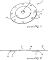
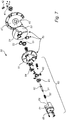
- Fig. 1 and Fig. 2 shows a mounting device 1 according to prior art.
- the mounting device according to prior art comprises a disk 11 having an outermost collar 12 with magnets 13 peripherally arranged in recesses.
- a hub 14 is arranged centrally in the disc 11, which hub 14 has an outermost diameter approximately corresponding to a bore diameter of a circular saw blade for mounting.
- the mounting device further has a bore 15 arranged within the center of the disc 11. This bore 15 is used for the assembling of the mounting device with the saw blade 80 within a grinding machine.
- such a mounting device give rise to tripled transfer of standard deviations, with a first standard deviation in the manufacturing of the saw blade 80 and the formation of the inner bore thereof, a second standard deviation of the hub 14 of the mounting device 1, and a third standard deviation of the center bore 15 in the mounting device, which center bore is then used for the mounting on a spindle within the grinding machine.
- Figs. 3 - 7 show a mounting device 30 according to one embodiment of the present invention.
- the mounting device 30 comprises a base plate 40, a centering element 50, and an actuator 60.
- a first surface 30-1 of the mounting device 30 is shown. This is the surface which faces and interacts with a mount within a grinding machine.
- a mounting bracket 41 is arranged for interaction with the mount within the grinding machine and in particular for locking the mounting device 30 with the saw blade 80 within the grinding machine.
- a stop shoulder 42 may be arranged. This stop shoulder 42 may interact with a corresponding recess in the mount within a grinding machine to prevent the base plate 40 from rotating within the grinding machine.
- a centrally arranged dowel 43 may be arranged.
- the dowel 43 may be used for securing and/or locking the mounting device 30 during the loading and/or unloading of a saw blade onto and off the mounting device 30.
- the dowel 43 may, as shown in this embodiment be screw fasten to the base plate 40.
- the dowel 43 has a through axially extending bore 44, which is more evident from Fig. 5 and 6 .
- a second surface 30-2 of the mounting device 30 is shown. This is the surface which faces and interacts with a saw blade 80 for securing and mounting the saw blade 80 onto the mounting device 30, and it is on this surface the centering element 50 is arranged.
- the centering element 50 comprises three engagement elements 51, three linear guideways 52, and a rotating disc 53.
- the engagement elements 51 are fasten to one linear guideways 52 each, and, in this embodiment, the linear guideways 52 are arranged within recesses 54 in the rotation disc 53.
- the linear guideways may not necessarily be arranged in recesses, instead the rotation disc 53 may be without any recesses, and instead have a uniform flat surface upon which the linear guideways are arranged.
- the centering element 50 is rotatably arranged in relation to the base plate 40 with bearings 55.
- the actuator 60 comprises a pin 61, which is configured to be operated in an axial direction A, and in the shown embodiment the pin 61 is a locating pin 61 comprising a shoulder 62. Further, in the shown embodiment the pin 61 is coaxially received in the through axially extending bore 44 in the dowel 43.
- the actuator 60 further comprises a transmission cross 63 arranged in cooperation with the shoulder 62 of the pin 61.
- the transmission cross 63 is further coupled with three pivot brackets 64 with articulated couplings 65, and the three pivot brackets 64 are fastened to one engagement element 51 each.
- the actuator 60 within the shown embodiment, comprises a cap 66, which is arranged on the second surface 30-2 of the mounting device 30 and arranged to extend coaxially with the pin 61 and circumferentially surround the pin 61 and also the transmission cross 63.
- the actuator 60 further comprises an elastic means 67, which elastic means 67 is arranged with springload between the transmission cross 63 and an inner surface 66-1 of the cap 66.
- this inner surface 66-1 of the cap 66 forms an abutment surface for the elastic means 67 in one end, while one surface of the transmission cross 63 forms an abutment surface for an opposite end of the elastic means 67.
- the cap 66 further has apertures 69 evenly arranged around the cap 66, which apertures 69 are arranged to allow movement of the articulated couplings 65 linking the transmission cross 63 arranged on the inside the cap 66 and the pivot brackets 64 arranged outside the cap 66.
- the cap 66 has a centrally arranged through-hole 68 in a surface of the cap 66 facing the second surface 30-2 of the mounting device 30.
- the pin 61 is, in the shown embodiment, arranged to extend from within the bore 44 and out through the centrally arranged through-hole 68 to the second surface 30-2 of the mounting device 30 being axially guided by the bore 44 in the dowel 43 and by the centrally arranged through-hole 68.
- the pin 61 In a resting position, the pin 61 is spring-loaded by the elastic means 67 such that the engagement elements 51 are set to a locking position L, as shown in Fig. 6 .
- the actuator 60 When loading a saw blade 80 onto the mounting device 30, the actuator 60 is activated by applying, through the bore 44 of the dowel 43, a pressure on the pin 61 to force the pin 61 in an axial direction A against the springload and towards the second surface 30-2 of the mounting device 30.
- a saw blade is thereafter loaded onto the mounting device 30 on the second surface 30-2 of the mounting device 30, placing the saw blade 80 to rest upon an engagement surface 45 adapted to engage a part of a side surface 80-1 of the saw blade 80.
- the cap 66 and the engagement elements 51 are positioned within a central bore 81 of the saw blade 80.
- the pressure applied on the pin 61 is relieved, and the spring-load urges the pin in the opposite axial direction towards the first surface 30-1, and this axial movement brings the engagement elements back towards the locking position L, pressing a peripheral outer edge portion 51-1 of each engagement element 51 to engage and press against an inner edge 81-1 of a bore 81 of the saw blade 80, thereby locking the saw blade 80 onto the mounting device 30.
- the mounting device 30 carrying the saw blade 80 is mounted into the grinding machine via the mounting bracket 41, and the stop shoulder 42 is positioned in a corresponding recess in the mount of the grinding machine, and the same is true for the dowel 43.
- the mounting device 30 may be used for manually loading the saw blade 80 onto the mounting device 30, and then manually mounting of the mounting device 30 with the saw blade 80 into a grinding machine.
- the mounting device 30 of the present invention is especially advantageous in that it may be operated by automatic robot handling, both for the part of loading/unloading of the saw blade 80 onto/off the mounting device 30, but also the handling of mounting/unmounting the mounting device 30 with the saw blade 80 in and/or out of the grinding machine.
- the cup 66 may be the gripping position for a robot grip.
- the mounting device 30 When loading or unloading the saw blade 80 onto or off the mounting device 30, the mounting device 30 may rest upon a flat surface with an opening for receiving the dowel 43, the mounting bracket 41 and the stop shoulder and a locking arrangement to engage the dowel 43 on the first surface 30-1 to secure the mounting device onto such a flat surface.
- the mounting bracket 41 may be used to lock and secure the mounting device with the saw blade within the grinding machine.
- the dowel 43 and the stop shoulder 42 rest in corresponding recesses in the mount within the grinding machine.
- the shown embodiment further has recesses 46 (see fig. 3 ) arranged on the engagement surface 45 of the base plate 40. Within these recesses magnets 47 are arranged and fastened. These magnets 47 are arranged to slow down the rotation of the saw blade 80 within the grinding machine. However, these magnets 47 are also part of the prior art solution, as shown in Fig. 1 with reference number 13.
- the magnets 47 may be screw fastened through recesses 48 arranged in the peripheral outer edge 40-1 of the base plate 40, but other fastening methods are also possible.
- the base plate 40 together with the dowel 43 and the pin 61 has a fixed position not rotating within the grinding machine.
- the successive teeth 82 on the edge of the saw blade 80 are placed one after the other in the grinding position within the grinding machine, the saw blade 80, the engagement elements 51, the rotation disc 53, the linear guideways 52, the pivot brackets 64, the articulated couplings 65, the transmission cross 63, the elastic means 67, and the cap 66 are all rotated together.
- the centering of the saw blade 80 will quicky and accurately be accomplished, as the engagement elements 51 are equally radially displaced by the actuator 60. Accordingly, any standard deviations present within the central bore 81 of the saw blade 80 will be compensated for within the mounting device 30 according to the present invention.
- the pin 61 may have an end part 61-1, extending out through the trough-hole 68 to the second side 30-2 and having a form which is configured to interact with a part of a robot head of an automatic mounting station to ensure proper automatic mounting within a grinding machine.
- the end part 61-1 of the pin has two parallell rectangular surfaces 61-2, which surfaces may interact with corresponding surfaces of a robot head of an automatic mounting station.
- centering element 50 having three engagement elements is shown, but the centering element 50 may comprise only two engagement elements 51, two linear guideways 52 and a rotating disc 53, but also four or more engagement elements 51, corresponding number of linear guideways 52, and a rotating disc 53.
Landscapes
- Engineering & Computer Science (AREA)
- Mechanical Engineering (AREA)
- Sawing (AREA)
- Finish Polishing, Edge Sharpening, And Grinding By Specific Grinding Devices (AREA)
- Constituent Portions Of Griding Lathes, Driving, Sensing And Control (AREA)
Claims (9)
- Dispositif de montage de scie circulaire (30) supportant une lame de scie (80) de façon rotative dans une meuleuse,
ledit dispositif de montage (30) comprenant :une plaque de base (40) adaptée pour un montage dans une meuleuse ; etun élément de centrage (50) comprenant au moins deux éléments d'engagement (51) configurés pour être actionnés dans une direction radiale entre une position de montage (M) et une position de verrouillage (L) ;caractérisé en ce que le dispositif de montage (30) comprend en outreun actionneur (60) comprenant une broche (61) configurée pour être actionnée dans une direction axiale (A) et conçue pour s'engager par des accouplements articulés de façon pivotante (63, 64, 65) avec chacun des éléments d'engagement pour ainsi transmettre un déplacement radial aux au moins deux éléments d'engagement (51) et pour ainsi actionner les au moins deux éléments d'engagement (51) entre la position de montage (M) et la position de verrouillage (L),dans lequel le dispositif de montage (30) présente, sur une première surface (30-1) de celui-ci, un support de montage (41) conçu pour le montage et le verrouillage du dispositif de montage (30) dans une meuleuse, etdans lequel l'élément de centrage (50) est disposé de façon rotative par rapport à la plaque de base (40) avec des paliers (55). - Dispositif de montage (30) selon la revendication 1, dans lequel l'élément de centrage (50) comprend au moins trois éléments d'engagement (51).
- Dispositif de montage (30) selon l'une quelconque des revendications précédentes, dans lequel la broche (61) est sollicitée par ressort par un moyen élastique (67) vers une position de repos dans laquelle les au moins deux éléments d'engagement (51) sont réglés sur la position de verrouillage (L).
- Dispositif de montage (30) selon l'une quelconque des revendications précédentes, dans lequel chacun des au moins deux éléments d'engagement (51) est formé comme un segment de cercle, une partie de bord extérieur périphérique de chaque segment formant une surface d'engagement (51-1) adaptée pour engager radialement un bord intérieur (81-1) d'un alésage central (81) d'une lame de scie (80).
- Dispositif de montage (30) selon l'une quelconque des revendications précédentes, dans lequel le dispositif de montage (30) présente, sur une première surface (30-1) de celui-ci, un goujon (43) disposé de façon centrale présentant un alésage (44) s'étendant axialement à travers celui-ci, et dans lequel la broche (61) est reçue coaxialement et apte à être actionnée axialement à l'intérieur dudit alésage (44).
- Dispositif de montage (30) selon l'une quelconque des revendications précédentes, dans lequel le dispositif de montage (30) comprend un capuchon (66) sur une deuxième surface (30-2) opposée à la première surface (30-1), ledit capuchon (66) étant disposé de manière à s'étendre coaxialement avec la broche (61) et à entourer ladite broche (61) circonférentiellement.
- Dispositif de montage (30) selon la revendication 7, dans lequel la broche (61) est disposée de manière à s'étendre depuis l'intérieur de l'alésage (44) du goujon (43) vers la deuxième surface (30-2) du dispositif de montage (30) tout en étant guidée axialement par l'alésage (44) du goujon (43) et par un trou de passage (68) disposé de façon centrale dans une surface du capuchon (66) tournée vers la deuxième surface (30-2) du dispositif de montage (30).
- Dispositif de montage (30) selon l'une quelconque des revendications 7 et 8, dans lequel une surface intérieure (66-1) du capuchon (66) fournit une butée (66-1) pour le moyen élastique (67).
- Dispositif de montage (30) selon l'une quelconque des revendications précédentes, dans lequel la plaque de base (40) sur la deuxième surface (30-2) du dispositif de montage (30) présente, dans une section extérieure périphérique, une surface d'engagement (45) adaptée pour engager une surface latérale (80-1) d'une lame de scie (80).
Applications Claiming Priority (2)
| Application Number | Priority Date | Filing Date | Title |
|---|---|---|---|
| SE1650554A SE540067C2 (en) | 2016-04-25 | 2016-04-25 | Circular saw mounting device |
| PCT/EP2017/059332 WO2017186551A1 (fr) | 2016-04-25 | 2017-04-20 | Dispositif de montage de scie circulaire |
Publications (2)
| Publication Number | Publication Date |
|---|---|
| EP3448611A1 EP3448611A1 (fr) | 2019-03-06 |
| EP3448611B1 true EP3448611B1 (fr) | 2020-05-27 |
Family
ID=58668849
Family Applications (1)
| Application Number | Title | Priority Date | Filing Date |
|---|---|---|---|
| EP17721071.3A Active EP3448611B1 (fr) | 2016-04-25 | 2017-04-20 | Dispositif de montage de scie circulaire |
Country Status (5)
| Country | Link |
|---|---|
| US (1) | US10792741B2 (fr) |
| EP (1) | EP3448611B1 (fr) |
| CA (1) | CA3022210C (fr) |
| SE (1) | SE540067C2 (fr) |
| WO (1) | WO2017186551A1 (fr) |
Cited By (1)
| Publication number | Priority date | Publication date | Assignee | Title |
|---|---|---|---|---|
| CN111872756A (zh) * | 2020-08-04 | 2020-11-03 | 浙江特佳利工具有限公司 | 一种合金锯片加工用具有防护结构的打磨装置 |
Families Citing this family (4)
| Publication number | Priority date | Publication date | Assignee | Title |
|---|---|---|---|---|
| US9796064B2 (en) | 2015-02-19 | 2017-10-24 | GM Global Technology Operations LLC | Quick change adapter for grinding wheels |
| US11027393B2 (en) * | 2017-05-08 | 2021-06-08 | Jason Brouk | Adjustable sander pad assembly |
| CN110788400A (zh) * | 2019-10-18 | 2020-02-14 | 缙云县先锋工具有限公司 | 一种具有开槽功能的数控磨齿机 |
| JP7479754B2 (ja) * | 2020-02-13 | 2024-05-09 | 株式会社ディスコ | 切削ブレード、及び切削ブレード装着機構 |
Family Cites Families (30)
| Publication number | Priority date | Publication date | Assignee | Title |
|---|---|---|---|---|
| US803604A (en) * | 1902-05-07 | 1905-11-07 | Philip F Krug | Chuck. |
| US1813705A (en) * | 1928-11-02 | 1931-07-07 | Baird Machine Co | Chuck |
| US3085813A (en) | 1960-04-27 | 1963-04-16 | Sp Mfg Corp | Quick change chuck |
| US3333857A (en) * | 1964-12-03 | 1967-08-01 | George V Lindgren | Universal grinding wheel chuck |
| US3646711A (en) * | 1969-08-12 | 1972-03-07 | Toyoda Machine Works Ltd | Mounting adapter assembly |
| US4251955A (en) * | 1979-01-29 | 1981-02-24 | The Warner & Swasey Company | Hub assembly |
| US4339893A (en) * | 1980-10-09 | 1982-07-20 | The Warner & Swasey Company | Quick release hub assembly |
| US4434684A (en) | 1982-04-12 | 1984-03-06 | Bell Industries, Inc. | Self-centering saw mount |
| US4598916A (en) * | 1984-12-06 | 1986-07-08 | Ukiah Machine & Welding Inc. | Magnetic saw chuck |
| US4657428A (en) * | 1985-09-10 | 1987-04-14 | Wiley Edward R | Quick change mechanism for circular saw blades and other spinning disc devices |
| US4730952A (en) * | 1986-08-04 | 1988-03-15 | Wiley Edward R | Quick change mechanism for circular saw blades |
| US4706386A (en) * | 1986-08-28 | 1987-11-17 | Wiley Edward R | Quick change mechanism for diamond arbor circular saw blades and other spinning disc devices |
| US4787147A (en) * | 1986-08-28 | 1988-11-29 | Wiley Edward R | Quick change mechanism for diamond arbor circular saw blades and other spinning disc devices using radially sliding locks |
| EP0569767B1 (fr) * | 1992-05-13 | 1996-01-03 | SCHOBER GmbH Werkzeug- und Maschinenbau | Support de couteau |
| CH688654A5 (fr) * | 1993-05-21 | 1997-12-31 | Speno International | Dispositif de fixation d'une meule lapidaire sur l'axe d'un moteur d'une unité de meulage d'un rail de chemin de fer. |
| SE510972C2 (sv) * | 1996-05-07 | 1999-07-19 | Atlas Copco Tools Ab | Portabelt kraftverktyg med balanseringsanordning |
| US6925718B2 (en) * | 1999-09-22 | 2005-08-09 | Andreas Stihl Ag & Co. | Tool head |
| DE10017980A1 (de) * | 2000-04-11 | 2001-10-25 | Bosch Gmbh Robert | Maschinenwerkzeugaufnahme |
| DE10222292A1 (de) * | 2002-05-18 | 2003-12-04 | Bosch Gmbh Robert | System mit einer Werkzeugaufnahme |
| US6887141B1 (en) * | 2004-02-06 | 2005-05-03 | Gison Machinery Co., Ltd. | Grinder with fast installable/detachable grinding disc |
| US7147550B2 (en) * | 2005-05-10 | 2006-12-12 | Sunmatch Industrial Co., Ltd. | Holding apparatus for grinding members |
| US7588484B2 (en) * | 2006-01-19 | 2009-09-15 | Nao Enterprises, Inc. | Mounting system for grinding wheels and the like |
| US7896729B2 (en) * | 2007-09-18 | 2011-03-01 | Hantover, Inc. | Universal rotary blade holder for sharpener |
| CN201711598U (zh) * | 2010-05-19 | 2011-01-19 | 南京德朔实业有限公司 | 切割件夹持装置 |
| DE102010043188A1 (de) * | 2010-10-29 | 2012-05-03 | Robert Bosch Gmbh | Ablaufsicherungsvorrichtung |
| DE102011075228B4 (de) * | 2011-05-04 | 2025-02-06 | Robert Bosch Gmbh | Oszillationswerkzeugspannvorrichtung |
| WO2013009729A1 (fr) * | 2011-07-12 | 2013-01-17 | Flowbelow, Llc. | Enjoliveurs aérodynamiques et ensembles de montage |
| ITBS20110121A1 (it) * | 2011-09-07 | 2013-03-08 | Utensilpava Affilatura Di Pavanelli Raffaele | Mandrino portautensile |
| US8997618B1 (en) * | 2013-01-23 | 2015-04-07 | Marjan Majcen | Quick release blade lock assembly |
| US9796064B2 (en) * | 2015-02-19 | 2017-10-24 | GM Global Technology Operations LLC | Quick change adapter for grinding wheels |
-
2016
- 2016-04-25 SE SE1650554A patent/SE540067C2/en unknown
-
2017
- 2017-04-20 US US16/095,997 patent/US10792741B2/en active Active
- 2017-04-20 CA CA3022210A patent/CA3022210C/fr active Active
- 2017-04-20 WO PCT/EP2017/059332 patent/WO2017186551A1/fr not_active Ceased
- 2017-04-20 EP EP17721071.3A patent/EP3448611B1/fr active Active
Non-Patent Citations (1)
| Title |
|---|
| None * |
Cited By (1)
| Publication number | Priority date | Publication date | Assignee | Title |
|---|---|---|---|---|
| CN111872756A (zh) * | 2020-08-04 | 2020-11-03 | 浙江特佳利工具有限公司 | 一种合金锯片加工用具有防护结构的打磨装置 |
Also Published As
| Publication number | Publication date |
|---|---|
| SE540067C2 (en) | 2018-03-13 |
| SE1650554A1 (en) | 2017-10-26 |
| EP3448611A1 (fr) | 2019-03-06 |
| US20190134726A1 (en) | 2019-05-09 |
| US10792741B2 (en) | 2020-10-06 |
| WO2017186551A1 (fr) | 2017-11-02 |
| CA3022210A1 (fr) | 2017-11-02 |
| CA3022210C (fr) | 2022-04-05 |
Similar Documents
| Publication | Publication Date | Title |
|---|---|---|
| CA3022210C (fr) | Dispositif de montage de scie circulaire | |
| CN213616061U (zh) | 夹持装置及包含夹持装置的夹持机台 | |
| US7207873B2 (en) | Hand machine tool with clamping device | |
| WO2013037424A1 (fr) | Mandrin expansible, système de serrage et procédé de serrage d'une pièce à travailler et d'un outil à une machine | |
| EP3202516B1 (fr) | Structure de mandrin | |
| US6481281B1 (en) | Wheel mount chuck and wheel mount method for vehicle wheel balancers | |
| AU2017283040B2 (en) | Rotationally drivable rotary tool device | |
| KR20190039727A (ko) | 전동 공구 | |
| EP2007547B1 (fr) | PROCÉDÉ ET APPAREIL DE FIXATION, SUR UNE PLAQUE DE PRÉPARATION ET D'APPUI, DE PIÈCES à USINER PAR DES MACHINES-OUTILS | |
| CN200988106Y (zh) | 双轴镗床自动定心夹具 | |
| CN104493221A (zh) | 一种固定式自动夹头 | |
| CN104647205B (zh) | 一种磨擦式自动夹头 | |
| EP2639566A1 (fr) | Dispositif de serrage de roue pour machine de maintenance de roues et procédé de montage de roue sur un dispositif de serrage de roue pour machine de maintenance de roue | |
| CN211489694U (zh) | 制动鼓车加工九点车夹具 | |
| US3665657A (en) | Apparatus for mounting disc brake rotors during truing | |
| US20200353589A1 (en) | Workpiece spindle for a magnetic-shoe external cylindrical grinding machine, and magnetic-shoe external cylindrical grinding machine | |
| CN104334301A (zh) | 平衡适配器 | |
| JP2013202746A (ja) | 加工機用の回転支持治具 | |
| US20040134590A1 (en) | Process and apparatus for subjecting workpieces having annular shape to machining of their inner and outer surfaces | |
| US4339893A (en) | Quick release hub assembly | |
| KR101897197B1 (ko) | 지렛대식 연삭기 크램프 | |
| US11879726B2 (en) | Method and apparatus for repairing truck and trailer axles | |
| US4132340A (en) | Welding method and apparatus | |
| JPH0753848Y2 (ja) | 研削盤用ワークドライブ装置 | |
| WO2007099653A1 (fr) | Rectifieuse plane a deux tetes de type vertical pour usiner un disque de frein |
Legal Events
| Date | Code | Title | Description |
|---|---|---|---|
| STAA | Information on the status of an ep patent application or granted ep patent |
Free format text: STATUS: UNKNOWN |
|
| STAA | Information on the status of an ep patent application or granted ep patent |
Free format text: STATUS: THE INTERNATIONAL PUBLICATION HAS BEEN MADE |
|
| PUAI | Public reference made under article 153(3) epc to a published international application that has entered the european phase |
Free format text: ORIGINAL CODE: 0009012 |
|
| STAA | Information on the status of an ep patent application or granted ep patent |
Free format text: STATUS: REQUEST FOR EXAMINATION WAS MADE |
|
| 17P | Request for examination filed |
Effective date: 20181120 |
|
| AK | Designated contracting states |
Kind code of ref document: A1 Designated state(s): AL AT BE BG CH CY CZ DE DK EE ES FI FR GB GR HR HU IE IS IT LI LT LU LV MC MK MT NL NO PL PT RO RS SE SI SK SM TR |
|
| AX | Request for extension of the european patent |
Extension state: BA ME |
|
| DAV | Request for validation of the european patent (deleted) | ||
| DAX | Request for extension of the european patent (deleted) | ||
| GRAP | Despatch of communication of intention to grant a patent |
Free format text: ORIGINAL CODE: EPIDOSNIGR1 |
|
| STAA | Information on the status of an ep patent application or granted ep patent |
Free format text: STATUS: GRANT OF PATENT IS INTENDED |
|
| INTG | Intention to grant announced |
Effective date: 20200109 |
|
| GRAS | Grant fee paid |
Free format text: ORIGINAL CODE: EPIDOSNIGR3 |
|
| GRAA | (expected) grant |
Free format text: ORIGINAL CODE: 0009210 |
|
| STAA | Information on the status of an ep patent application or granted ep patent |
Free format text: STATUS: THE PATENT HAS BEEN GRANTED |
|
| AK | Designated contracting states |
Kind code of ref document: B1 Designated state(s): AL AT BE BG CH CY CZ DE DK EE ES FI FR GB GR HR HU IE IS IT LI LT LU LV MC MK MT NL NO PL PT RO RS SE SI SK SM TR |
|
| REG | Reference to a national code |
Ref country code: GB Ref legal event code: FG4D |
|
| REG | Reference to a national code |
Ref country code: CH Ref legal event code: EP |
|
| REG | Reference to a national code |
Ref country code: AT Ref legal event code: REF Ref document number: 1274055 Country of ref document: AT Kind code of ref document: T Effective date: 20200615 |
|
| REG | Reference to a national code |
Ref country code: DE Ref legal event code: R096 Ref document number: 602017017319 Country of ref document: DE |
|
| REG | Reference to a national code |
Ref country code: LT Ref legal event code: MG4D |
|
| PG25 | Lapsed in a contracting state [announced via postgrant information from national office to epo] |
Ref country code: NO Free format text: LAPSE BECAUSE OF FAILURE TO SUBMIT A TRANSLATION OF THE DESCRIPTION OR TO PAY THE FEE WITHIN THE PRESCRIBED TIME-LIMIT Effective date: 20200827 Ref country code: FI Free format text: LAPSE BECAUSE OF FAILURE TO SUBMIT A TRANSLATION OF THE DESCRIPTION OR TO PAY THE FEE WITHIN THE PRESCRIBED TIME-LIMIT Effective date: 20200527 Ref country code: GR Free format text: LAPSE BECAUSE OF FAILURE TO SUBMIT A TRANSLATION OF THE DESCRIPTION OR TO PAY THE FEE WITHIN THE PRESCRIBED TIME-LIMIT Effective date: 20200828 Ref country code: IS Free format text: LAPSE BECAUSE OF FAILURE TO SUBMIT A TRANSLATION OF THE DESCRIPTION OR TO PAY THE FEE WITHIN THE PRESCRIBED TIME-LIMIT Effective date: 20200927 Ref country code: PT Free format text: LAPSE BECAUSE OF FAILURE TO SUBMIT A TRANSLATION OF THE DESCRIPTION OR TO PAY THE FEE WITHIN THE PRESCRIBED TIME-LIMIT Effective date: 20200928 Ref country code: SE Free format text: LAPSE BECAUSE OF FAILURE TO SUBMIT A TRANSLATION OF THE DESCRIPTION OR TO PAY THE FEE WITHIN THE PRESCRIBED TIME-LIMIT Effective date: 20200527 Ref country code: LT Free format text: LAPSE BECAUSE OF FAILURE TO SUBMIT A TRANSLATION OF THE DESCRIPTION OR TO PAY THE FEE WITHIN THE PRESCRIBED TIME-LIMIT Effective date: 20200527 |
|
| REG | Reference to a national code |
Ref country code: NL Ref legal event code: MP Effective date: 20200527 |
|
| PG25 | Lapsed in a contracting state [announced via postgrant information from national office to epo] |
Ref country code: BG Free format text: LAPSE BECAUSE OF FAILURE TO SUBMIT A TRANSLATION OF THE DESCRIPTION OR TO PAY THE FEE WITHIN THE PRESCRIBED TIME-LIMIT Effective date: 20200827 Ref country code: RS Free format text: LAPSE BECAUSE OF FAILURE TO SUBMIT A TRANSLATION OF THE DESCRIPTION OR TO PAY THE FEE WITHIN THE PRESCRIBED TIME-LIMIT Effective date: 20200527 Ref country code: LV Free format text: LAPSE BECAUSE OF FAILURE TO SUBMIT A TRANSLATION OF THE DESCRIPTION OR TO PAY THE FEE WITHIN THE PRESCRIBED TIME-LIMIT Effective date: 20200527 Ref country code: HR Free format text: LAPSE BECAUSE OF FAILURE TO SUBMIT A TRANSLATION OF THE DESCRIPTION OR TO PAY THE FEE WITHIN THE PRESCRIBED TIME-LIMIT Effective date: 20200527 |
|
| REG | Reference to a national code |
Ref country code: AT Ref legal event code: MK05 Ref document number: 1274055 Country of ref document: AT Kind code of ref document: T Effective date: 20200527 |
|
| PG25 | Lapsed in a contracting state [announced via postgrant information from national office to epo] |
Ref country code: NL Free format text: LAPSE BECAUSE OF FAILURE TO SUBMIT A TRANSLATION OF THE DESCRIPTION OR TO PAY THE FEE WITHIN THE PRESCRIBED TIME-LIMIT Effective date: 20200527 Ref country code: AL Free format text: LAPSE BECAUSE OF FAILURE TO SUBMIT A TRANSLATION OF THE DESCRIPTION OR TO PAY THE FEE WITHIN THE PRESCRIBED TIME-LIMIT Effective date: 20200527 |
|
| PG25 | Lapsed in a contracting state [announced via postgrant information from national office to epo] |
Ref country code: ES Free format text: LAPSE BECAUSE OF FAILURE TO SUBMIT A TRANSLATION OF THE DESCRIPTION OR TO PAY THE FEE WITHIN THE PRESCRIBED TIME-LIMIT Effective date: 20200527 Ref country code: CZ Free format text: LAPSE BECAUSE OF FAILURE TO SUBMIT A TRANSLATION OF THE DESCRIPTION OR TO PAY THE FEE WITHIN THE PRESCRIBED TIME-LIMIT Effective date: 20200527 Ref country code: DK Free format text: LAPSE BECAUSE OF FAILURE TO SUBMIT A TRANSLATION OF THE DESCRIPTION OR TO PAY THE FEE WITHIN THE PRESCRIBED TIME-LIMIT Effective date: 20200527 Ref country code: EE Free format text: LAPSE BECAUSE OF FAILURE TO SUBMIT A TRANSLATION OF THE DESCRIPTION OR TO PAY THE FEE WITHIN THE PRESCRIBED TIME-LIMIT Effective date: 20200527 Ref country code: SM Free format text: LAPSE BECAUSE OF FAILURE TO SUBMIT A TRANSLATION OF THE DESCRIPTION OR TO PAY THE FEE WITHIN THE PRESCRIBED TIME-LIMIT Effective date: 20200527 Ref country code: AT Free format text: LAPSE BECAUSE OF FAILURE TO SUBMIT A TRANSLATION OF THE DESCRIPTION OR TO PAY THE FEE WITHIN THE PRESCRIBED TIME-LIMIT Effective date: 20200527 Ref country code: RO Free format text: LAPSE BECAUSE OF FAILURE TO SUBMIT A TRANSLATION OF THE DESCRIPTION OR TO PAY THE FEE WITHIN THE PRESCRIBED TIME-LIMIT Effective date: 20200527 |
|
| PG25 | Lapsed in a contracting state [announced via postgrant information from national office to epo] |
Ref country code: SK Free format text: LAPSE BECAUSE OF FAILURE TO SUBMIT A TRANSLATION OF THE DESCRIPTION OR TO PAY THE FEE WITHIN THE PRESCRIBED TIME-LIMIT Effective date: 20200527 Ref country code: PL Free format text: LAPSE BECAUSE OF FAILURE TO SUBMIT A TRANSLATION OF THE DESCRIPTION OR TO PAY THE FEE WITHIN THE PRESCRIBED TIME-LIMIT Effective date: 20200527 |
|
| REG | Reference to a national code |
Ref country code: DE Ref legal event code: R097 Ref document number: 602017017319 Country of ref document: DE |
|
| PLBE | No opposition filed within time limit |
Free format text: ORIGINAL CODE: 0009261 |
|
| STAA | Information on the status of an ep patent application or granted ep patent |
Free format text: STATUS: NO OPPOSITION FILED WITHIN TIME LIMIT |
|
| 26N | No opposition filed |
Effective date: 20210302 |
|
| PG25 | Lapsed in a contracting state [announced via postgrant information from national office to epo] |
Ref country code: SI Free format text: LAPSE BECAUSE OF FAILURE TO SUBMIT A TRANSLATION OF THE DESCRIPTION OR TO PAY THE FEE WITHIN THE PRESCRIBED TIME-LIMIT Effective date: 20200527 |
|
| PG25 | Lapsed in a contracting state [announced via postgrant information from national office to epo] |
Ref country code: MC Free format text: LAPSE BECAUSE OF FAILURE TO SUBMIT A TRANSLATION OF THE DESCRIPTION OR TO PAY THE FEE WITHIN THE PRESCRIBED TIME-LIMIT Effective date: 20200527 |
|
| GBPC | Gb: european patent ceased through non-payment of renewal fee |
Effective date: 20210420 |
|
| PG25 | Lapsed in a contracting state [announced via postgrant information from national office to epo] |
Ref country code: LU Free format text: LAPSE BECAUSE OF NON-PAYMENT OF DUE FEES Effective date: 20210420 |
|
| REG | Reference to a national code |
Ref country code: BE Ref legal event code: MM Effective date: 20210430 |
|
| PG25 | Lapsed in a contracting state [announced via postgrant information from national office to epo] |
Ref country code: GB Free format text: LAPSE BECAUSE OF NON-PAYMENT OF DUE FEES Effective date: 20210420 |
|
| PG25 | Lapsed in a contracting state [announced via postgrant information from national office to epo] |
Ref country code: IE Free format text: LAPSE BECAUSE OF NON-PAYMENT OF DUE FEES Effective date: 20210420 |
|
| PG25 | Lapsed in a contracting state [announced via postgrant information from national office to epo] |
Ref country code: BE Free format text: LAPSE BECAUSE OF NON-PAYMENT OF DUE FEES Effective date: 20210430 |
|
| P01 | Opt-out of the competence of the unified patent court (upc) registered |
Effective date: 20230404 |
|
| PG25 | Lapsed in a contracting state [announced via postgrant information from national office to epo] |
Ref country code: CY Free format text: LAPSE BECAUSE OF FAILURE TO SUBMIT A TRANSLATION OF THE DESCRIPTION OR TO PAY THE FEE WITHIN THE PRESCRIBED TIME-LIMIT Effective date: 20200527 |
|
| PG25 | Lapsed in a contracting state [announced via postgrant information from national office to epo] |
Ref country code: HU Free format text: LAPSE BECAUSE OF FAILURE TO SUBMIT A TRANSLATION OF THE DESCRIPTION OR TO PAY THE FEE WITHIN THE PRESCRIBED TIME-LIMIT; INVALID AB INITIO Effective date: 20170420 |
|
| PG25 | Lapsed in a contracting state [announced via postgrant information from national office to epo] |
Ref country code: MK Free format text: LAPSE BECAUSE OF FAILURE TO SUBMIT A TRANSLATION OF THE DESCRIPTION OR TO PAY THE FEE WITHIN THE PRESCRIBED TIME-LIMIT Effective date: 20200527 |
|
| PG25 | Lapsed in a contracting state [announced via postgrant information from national office to epo] |
Ref country code: MT Free format text: LAPSE BECAUSE OF FAILURE TO SUBMIT A TRANSLATION OF THE DESCRIPTION OR TO PAY THE FEE WITHIN THE PRESCRIBED TIME-LIMIT Effective date: 20200527 |
|
| PGFP | Annual fee paid to national office [announced via postgrant information from national office to epo] |
Ref country code: DE Payment date: 20250318 Year of fee payment: 9 |
|
| PGFP | Annual fee paid to national office [announced via postgrant information from national office to epo] |
Ref country code: CH Payment date: 20250501 Year of fee payment: 9 |
|
| PGFP | Annual fee paid to national office [announced via postgrant information from national office to epo] |
Ref country code: TR Payment date: 20250414 Year of fee payment: 9 |
|
| PGFP | Annual fee paid to national office [announced via postgrant information from national office to epo] |
Ref country code: IT Payment date: 20260319 Year of fee payment: 10 |
|
| PGFP | Annual fee paid to national office [announced via postgrant information from national office to epo] |
Ref country code: FR Payment date: 20260316 Year of fee payment: 10 |
|
| REG | Reference to a national code |
Ref country code: CH Ref legal event code: U11 Free format text: ST27 STATUS EVENT CODE: U-0-0-U10-U11 (AS PROVIDED BY THE NATIONAL OFFICE) Effective date: 20260501 |